EP3046234A1 - Method and apparatus for shaping at least one alternator bar - Google Patents
Method and apparatus for shaping at least one alternator bar Download PDFInfo
- Publication number
- EP3046234A1 EP3046234A1 EP16151366.8A EP16151366A EP3046234A1 EP 3046234 A1 EP3046234 A1 EP 3046234A1 EP 16151366 A EP16151366 A EP 16151366A EP 3046234 A1 EP3046234 A1 EP 3046234A1
- Authority
- EP
- European Patent Office
- Prior art keywords
- bar
- shaping
- assembly
- guide
- shape
- Prior art date
- Legal status (The legal status is an assumption and is not a legal conclusion. Google has not performed a legal analysis and makes no representation as to the accuracy of the status listed.)
- Granted
Links
Images



Classifications
-
- H—ELECTRICITY
- H02—GENERATION; CONVERSION OR DISTRIBUTION OF ELECTRIC POWER
- H02K—DYNAMO-ELECTRIC MACHINES
- H02K15/00—Processes or apparatus specially adapted for manufacturing, assembling, maintaining or repairing of dynamo-electric machines
- H02K15/04—Processes or apparatus specially adapted for manufacturing, assembling, maintaining or repairing of dynamo-electric machines of windings prior to their mounting into the machines
- H02K15/0414—Processes or apparatus specially adapted for manufacturing, assembling, maintaining or repairing of dynamo-electric machines of windings prior to their mounting into the machines the windings consisting of separate elements, e.g. bars, segments or half coils
-
- H—ELECTRICITY
- H02—GENERATION; CONVERSION OR DISTRIBUTION OF ELECTRIC POWER
- H02K—DYNAMO-ELECTRIC MACHINES
- H02K15/00—Processes or apparatus specially adapted for manufacturing, assembling, maintaining or repairing of dynamo-electric machines
- H02K15/04—Processes or apparatus specially adapted for manufacturing, assembling, maintaining or repairing of dynamo-electric machines of windings prior to their mounting into the machines
- H02K15/0414—Processes or apparatus specially adapted for manufacturing, assembling, maintaining or repairing of dynamo-electric machines of windings prior to their mounting into the machines the windings consisting of separate elements, e.g. bars, segments or half coils
- H02K15/0421—Processes or apparatus specially adapted for manufacturing, assembling, maintaining or repairing of dynamo-electric machines of windings prior to their mounting into the machines the windings consisting of separate elements, e.g. bars, segments or half coils and consisting of single conductors, e.g. hairpins
-
- B—PERFORMING OPERATIONS; TRANSPORTING
- B21—MECHANICAL METAL-WORKING WITHOUT ESSENTIALLY REMOVING MATERIAL; PUNCHING METAL
- B21D—WORKING OR PROCESSING OF SHEET METAL OR METAL TUBES, RODS OR PROFILES WITHOUT ESSENTIALLY REMOVING MATERIAL; PUNCHING METAL
- B21D7/00—Bending rods, profiles, or tubes
- B21D7/04—Bending rods, profiles, or tubes over a movably-arranged forming menber
-
- B—PERFORMING OPERATIONS; TRANSPORTING
- B21—MECHANICAL METAL-WORKING WITHOUT ESSENTIALLY REMOVING MATERIAL; PUNCHING METAL
- B21D—WORKING OR PROCESSING OF SHEET METAL OR METAL TUBES, RODS OR PROFILES WITHOUT ESSENTIALLY REMOVING MATERIAL; PUNCHING METAL
- B21D7/00—Bending rods, profiles, or tubes
- B21D7/12—Bending rods, profiles, or tubes with program control
Definitions
- the present invention relates to a method and an apparatus for shaping at least one bar of a winding of an alternator.
- the present invention relates to a method and an apparatus for shaping at least one bar of a rotor winding of an alternator of an electrical energy production plant.
- Plants for the production of electrical energy usually comprise at least one rotary turbine (a steam turbine and/ or a gas turbine), which drags an alternator, which is configured to produce electrical energy.
- a rotary turbine a steam turbine and/ or a gas turbine
- an alternator which is configured to produce electrical energy.
- Known alternators extend along a longitudinal axis and are provided with a fixed part, the stator, and a movable part, the rotor.
- the rotor is housed on the inside of the stator and is supported by two bearings, which are fitted to the rotary shaft of the alternator.
- the rotor configured in this way, rotates dragged by the turbine.
- the rotor is configured so as to generate a magnetic field, which induces an electromotive force in the stator, and is provided with electrical windings.
- a collector assembly which is fitted to the rotor, receives electric current from an excitation system and supplies power to the electrical windings of the rotor.
- windings are usually defined by conductor bars, generally made of copper, which extend along a path that comprises, in the area of the heads of the rotor, curved portions.
- the shaping of the conductor bars is usually carried out by means of a dedicated apparatus, which is handled by an operator, who must be very careful and an expert of this kind of operations.
- a dedicated apparatus which is handled by an operator, who must be very careful and an expert of this kind of operations.
- it often happens that the final geometry of the conductor bars does not fulfil the requirements of the design plan, despite the dedication and the experience of the operator.
- an object of the present invention is to provide an apparatus for shaping at least one alternator bar, which overcomes the drawbacks of the prior art mentioned above; in particular, an object of the present invention is to provide an apparatus for shaping at least one alternator bar, which minimizes the hand work to be carried out by the operator and ensures a bending of the bars that meets the requirements of the design plan in a simple and low-cost manner, both in functional terms and in constructive terms.
- the present invention relates to an apparatus for shaping at least one alternator bar, comprising:
- a further object of the present invention is to provide a method for bending at least one alternator bar, which can bend the bar minimizing the hand work to be carried out by the operator and can meet the requirements of the design plan in a simple and low-cost manner.
- the present invention relates to a method for shaping at least one alternator bar, comprising the steps of:
- number 1 indicates an apparatus for shaping at least one bar 2 of an alternator (which is not shown in the accompanying figures).
- the bar 2 is a rotor conductor bar of an alternator of a plant for the production of electrical energy.
- the alternator bars 2 to be shaped are provided in a substantially pre-processed configuration.
- the bar 2 to be shaped is provided with a first central straight stroke 2a, which is adapted to be arranged in a respective rotor slot, and with two end strokes 2b, which are straight and are arranged substantially orthogonal to the first stroke 2a.
- the strokes 2b are shaped by the apparatus 1 according to the present invention.
- the strokes 2b are simultaneously shaped by the apparatus 1.
- the apparatus 1 comprises a locking assembly 3, at least one shaping assembly 4 (schematically shown in figure 1 and better displayed in the following figures), at least one cutting assembly 5 (schematically shown in figure 1 and better displayed in the following figures) and a control device 6 (shown in figure 2 ).
- the apparatus 1 comprises two shaping assemblies 4, which are configured to shape respective strokes 2b of the bar 2, and two cutting assemblies 5, which are configured to cut the strokes 2b of the bar 2 at the end of the shaping.
- the apparatus 1 comprises an automatic loading and unloading device for the bars 2, which is not clearly visible in the accompanying drawings. This device is configured to pick up the bars 2 and position them in a predetermined seat.
- Figure 1 shows a bar 2, which is already positioned so that the strokes 2b can be subjected to the shaping.
- the apparatus 1 comprises, furthermore, a moving assembly 7 (schematically shown in figure 1 and better displayed in the following figures), which is configured to move the shaping assemblies 4 and the cutting assemblies 5 and is regulated by the control device 6.
- a moving assembly 7 (schematically shown in figure 1 and better displayed in the following figures), which is configured to move the shaping assemblies 4 and the cutting assemblies 5 and is regulated by the control device 6.
- the moving assembly 7 is configured to move each shaping assembly 4 and each cutting assembly 5 along three different directions X, Y and Z indicated in figure 1 .
- each shaping assembly 4 is coupled to a cutting assembly 5.
- the moving assembly 7 moves two groups, which are each made up of a shaping assembly 4 and a cutting assembly 5.
- the locking assembly 3 is configured to steadily lock the bars 2, so as to allow the shaping assembly 4 to act upon a stationary bar.
- the locking assembly 3 comprises three locking elements 3a, 3b and 3c, which are arranged along the stroke 2a of the bar 2.
- Each locking element 3a, 3b, 3c comprises at least one locking clamp (not shown in the accompanying figures for greater clarity) and a respective supporting element 8a, 8b, 8c, which is configured to support the clamp and the bar 2.
- the moving assembly 7 comprises a first moving unit 10, which is adapted to move one of the two shaping assemblies 4 and one of the two cutting assemblies 5, and a second moving unit 11, which is adapted to move the other one of the two shaping assemblies 4 and the other one of the two cutting assemblies 5.
- the first moving unit 10 and the second moving unit 11 are substantially identical. Therefore, for the sake of simplicity, hereinafter we will describe the sole moving unit 10.
- the moving unit 10 comprises a carriage 12, a first guide 13, a second guide 14 and a third guide 15 (partially visible in figure 1 ).
- the carriage 12 supports the shaping assembly 4 and the cutting assembly 5 and is provided with a driving member (not shown in the accompanying figures), whose operation is controlled by the control device 6.
- the first guide 13, the second guide 14 and the third guide 15 are arranged orthogonal to one another along the three directions X, Y and Z, respectively.
- the carriage 12 is movable along the first guide 13.
- the first guide 13 is movable along the second guide 14.
- the second guide 14 is movable along the third guide 15.
- the first guide 13 and the second guide 14 are each provided with a carriage and a driving member (not shown in the accompanying figures), which are arranged at the back of the respective guide 13 and 14 and are regulated by the control device 6.
- the controlled movements of the carriage 12, of the first guide 13 and of the second guide 14 allow the shaping assembly 4 and the cutting unit 5 to be positioned along the portion of the bar 2b to be shaped.
- the moving units 10, 11 are cable moving units.
- the shaping assembly 4 is preferably configured to shape one bar 2 at a time.
- the shaping assembly 4 is preferably configured to shape the bar 2 so that the portion of the bar 2 subjected to the shaping has the shape of a polygon section resembling a circumference portion (see the shaped portion of the bar 2 visible in figure 2 ).
- the shaping assembly 4 is configured to shape the bar 2 so that the portion of the bar 2 subjected to the shaping has a shape defined by a plurality of straight strokes having a given length and a given slope.
- the number of broken lines determines the width of the bending, whereas the length of each straight stroke defines the shaping radius.
- the shaping of the bar 2 according to a polygonal chain is more stable compared to the shaping that could be obtained so far with the prior art. Indeed, in the vertices of each single straight stroke there is an axial load that is such as to steadily deform, in one single phase, the copper defining the bar 2.
- the shaping assembly 4 comprises a clamping unit 16 and a deformation unit 17, which are arranged in close succession, so as to obtain the shaping of the bar 2.
- the bar 2 is kept in a given position by the clamping unit 16 and is properly deformed by the deformation unit 17.
- the clamping unit 16 comprises a plurality of clamping elements 18 which can be positioned independently from one another so as to define a clamp that is adaptable to the shape of the portion of the bar 2 to be clamped. By so doing, the clamping unit 16 can keep in position both straight strokes of the bar 2 and curved strokes.
- clamping elements 18 are divided into an inner group 19 and an outer group 20.
- the inner group 19 comprises three clamping elements 18, which are arranged beside one another so as to substantially define an inner clamping surface 21
- the outer group 20 comprises three further clamping elements 18, which are arranged beside one another so as to substantially define an outer clamping surface 22, which faces the inner clamping surface 21.
- the clamping elements 18 of the inner group 19 and of the outer group 20 are moved so as to get close to and strike against the respective portion of the bar 2, and then they are kept in position so as to exert a force that is able to counter the bending moment exerted by the deformation unit 17.
- each clamping element 18 is coupled to a respective actuator 23, which is regulated by the control device 6.
- the actuator 23 is regulated so as to determine a controlled movement of the respective clamping element 18 as it gets close to and strikes against the bar 2, in such a way that undesired deformations of the bar 2 are avoided, and it is regulated so as to determine a locking of the respective clamping element 18 that is stable and resistant to the bending moment.
- the actuator 23 is a pneumatic actuator, preferably with a small bore (for example, 40 mm), provided with a respective tightening bushing 24.
- the tightening bushing 24 preferably is hydraulic.
- each tightening bushing 24 is configured to keep the respective actuator 23 in a static position and to ensure an axial hold of approximately 5 kN.
- the deformation unit 17, as already mentioned above, is arranged downstream of the clamping unit 16 and is configured to exert a bending moment upon the portion of the bar 2 projecting from the clamping unit 16.
- the deformation unit 17 comprises an abutment element 25 and a pressing element 26 configured to apply a pressing force on the portion of the bar 2, which comes out from the clamping unit 16 and which is arranged between the abutment element 25 and the pressing element 26.
- the pressing element 26 comprises a head 28 and an actuator 29.
- the actuator 29 is a hydraulic actuator.
- the pressing element 26 can be oriented thanks to a support system 30 that is schematically shown in figure 2 .
- the pressing element 16 can exert the pressing force along a preferred direction of deformation.
- the support system 30 comprises a rotation member (schematically shown in figure 3 ) comprising a precision reduction gear with a toothed belt.
- the abutment element 25 is configured to create a lever point and enable the bending of the bar 2 subjected to the pressing force of the pressing element 26.
- the abutment element 25 has an outer profile that is concave and substantially semicircular.
- the pressing element 26 is arranged so as to apply a pressing force on the face 31 of the bar 2 which has a concave profile after the deformation (see also figure 2 ).
- the pressing element 26 is arranged so as to exert the deformation force upon the face 31 of the bar 2 that is considered as the "outer" face.
- the geometric shaping of the bar 2 is more precise both if you are using soft copper (weak and more ductile) and if you are using rigid copper (provided with a high elasticity).
- the pressing element 26 is arranged so as to exert the deformation force upon the so-called "outer" face 31 of the bar 2, the elongation of the bar 2, which might be caused by deformation forces, accumulates in the end part of the bar 2, which will be cut by the cutting assembly 5.
- the cutting assembly 5 is configured to cut the bar 2 at the end of the shaping cycle by means of a hydraulically-operated cutting device 32.
- the cutting assembly 5 is arranged downstream of the shaping assembly 4 (see figure 1 ).
- the fact that the cut is carried out after the shaping allows operators to correct possible mistakes made during the shaping step.
- the cutting assembly 5 arranged downstream of the shaping assembly 4 allows waste swarf to be minimized, thus preserving the general cleanliness of the apparatus 1.
- the cutting assembly 5 is coupled to the respective shaping assembly 4 so that the first moving unit 10 and the second moving unit 11 move not only the shaping assembly 4 but also the respective cutting assembly 5.
- the positioning of the cutting assembly 5 along the bar 2 is regulated by the control device 6.
- control device 6, at the end of the shaping cycle is configured to position the cutting assembly 5 at the desired height, which includes the possible deformation error.
- the cutting assembly 5 described and shown herein is very compact and can be moved within very small spaces.
- the method for shaping at least one alternator bar 2 according to the present invention substantially comprises the steps of:
- the portion of the bar 2 that is first shaped by the shaping assembly 4 belongs to the second stroke 2b of the bar 2 and is proximal to the first stroke 2a.
- the shaping assembly 4 is moved so as to progressively shape all the portions following the second stroke 2b of the bar 2, which are farther and farther from the first stroke 2a. In this way, possible mistakes due to the elongation of the bar 2 during its processing are gathered in the last distal portion of the second stroke 2b, which will be cut.
- control device 6 is responsible for the numerical control of the entire apparatus 1.
- the apparatus 1 can automatically shape one bar 2 at a time, thus creating a polygonal chain of straight strokes resembling the desired circumference.
- the apparatus 1 is designed to operate with fixed parameters, except for the definition of the number and the length of the strokes making up the polygonal chain to be obtained. These parameters, indeed, can be changed based on the requirements of the design plan.
- the apparatus 1 determines a shaping of the bar 2 that is quick and, at the same time, precise.
- the apparatus 1 according to the present invention is very compact and can operate along strokes of the bar 2 that are not very long. This is mainly due to the structure of the clamping unit 14, which is provided with clamping elements 17 that adjust to the shape of the bar 2.
Landscapes
- Engineering & Computer Science (AREA)
- Mechanical Engineering (AREA)
- Manufacturing & Machinery (AREA)
- Power Engineering (AREA)
- Manufacture Of Motors, Generators (AREA)
Abstract
Description
- The present invention relates to a method and an apparatus for shaping at least one bar of a winding of an alternator. In particular, the present invention relates to a method and an apparatus for shaping at least one bar of a rotor winding of an alternator of an electrical energy production plant.
- Plants for the production of electrical energy usually comprise at least one rotary turbine (a steam turbine and/ or a gas turbine), which drags an alternator, which is configured to produce electrical energy.
- Known alternators extend along a longitudinal axis and are provided with a fixed part, the stator, and a movable part, the rotor.
- The rotor is housed on the inside of the stator and is supported by two bearings, which are fitted to the rotary shaft of the alternator.
- The rotor, configured in this way, rotates dragged by the turbine.
- The rotor is configured so as to generate a magnetic field, which induces an electromotive force in the stator, and is provided with electrical windings. A collector assembly, which is fitted to the rotor, receives electric current from an excitation system and supplies power to the electrical windings of the rotor.
- These windings are usually defined by conductor bars, generally made of copper, which extend along a path that comprises, in the area of the heads of the rotor, curved portions.
- The shaping of the conductor bars is usually carried out by means of a dedicated apparatus, which is handled by an operator, who must be very careful and an expert of this kind of operations. However, it often happens that the final geometry of the conductor bars does not fulfil the requirements of the design plan, despite the dedication and the experience of the operator.
- Therefore, an object of the present invention is to provide an apparatus for shaping at least one alternator bar, which overcomes the drawbacks of the prior art mentioned above; in particular, an object of the present invention is to provide an apparatus for shaping at least one alternator bar, which minimizes the hand work to be carried out by the operator and ensures a bending of the bars that meets the requirements of the design plan in a simple and low-cost manner, both in functional terms and in constructive terms.
- In accordance with these objects, the present invention relates to an apparatus for shaping at least one alternator bar, comprising:
- at least one shaping assembly configured to shape at least one portion of the bar;
- a moving assembly configured to move at least the shaping assembly with respect to the bar.
- A further object of the present invention is to provide a method for bending at least one alternator bar, which can bend the bar minimizing the hand work to be carried out by the operator and can meet the requirements of the design plan in a simple and low-cost manner.
- In accordance with these objects, the present invention relates to a method for shaping at least one alternator bar, comprising the steps of:
- positioning at least one shaping assembly by a first portion of the bar to be shaped;
- shaping the first portion of the bar by means of the shaping assembly.
- Further features and advantages of the invention will be best understood upon perusal of the following description of a non-limiting embodiment thereof, with reference to the accompanying drawing, wherein:
-
figure 1 is a schematic perspective view, with parts removed for greater clarity, of the apparatus for bending at least one alternator bar according to the present invention; -
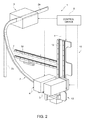
figure 2 is a schematic perspective view, with cross-sectional parts and parts removed for greater clarity, of a first detail of the apparatus offigure 1 ; -
figure 3 is a schematic perspective view, with cross-sectional parts and parts removed for greater clarity, of a second detail of the apparatus offigure 1 ; -
figure 4 is a schematic perspective view, with cross-sectional parts and parts removed for greater clarity, of a third detail of the apparatus offigure 1 . - In
figure 1 , number 1 indicates an apparatus for shaping at least onebar 2 of an alternator (which is not shown in the accompanying figures). - Preferably, the
bar 2 is a rotor conductor bar of an alternator of a plant for the production of electrical energy. - Obviously, the apparatus and the method described herein can be also applied to stator conductor bars.
- The
alternator bars 2 to be shaped are provided in a substantially pre-processed configuration. In detail, thebar 2 to be shaped is provided with a first centralstraight stroke 2a, which is adapted to be arranged in a respective rotor slot, and with twoend strokes 2b, which are straight and are arranged substantially orthogonal to thefirst stroke 2a. Thestrokes 2b are shaped by the apparatus 1 according to the present invention. - Preferably, the
strokes 2b are simultaneously shaped by the apparatus 1. - The apparatus 1 comprises a
locking assembly 3, at least one shaping assembly 4 (schematically shown infigure 1 and better displayed in the following figures), at least one cutting assembly 5 (schematically shown infigure 1 and better displayed in the following figures) and a control device 6 (shown infigure 2 ). - In particular, the apparatus 1 comprises two
shaping assemblies 4, which are configured to shaperespective strokes 2b of thebar 2, and twocutting assemblies 5, which are configured to cut thestrokes 2b of thebar 2 at the end of the shaping. - The apparatus 1 comprises an automatic loading and unloading device for the
bars 2, which is not clearly visible in the accompanying drawings. This device is configured to pick up thebars 2 and position them in a predetermined seat. -
Figure 1 shows abar 2, which is already positioned so that thestrokes 2b can be subjected to the shaping. - The apparatus 1 comprises, furthermore, a moving assembly 7 (schematically shown in
figure 1 and better displayed in the following figures), which is configured to move theshaping assemblies 4 and thecutting assemblies 5 and is regulated by thecontrol device 6. - In particular, the
moving assembly 7 is configured to move eachshaping assembly 4 and eachcutting assembly 5 along three different directions X, Y and Z indicated infigure 1 . - In the non-limiting embodiment described and shown herein, each
shaping assembly 4 is coupled to acutting assembly 5. In this way, themoving assembly 7 moves two groups, which are each made up of ashaping assembly 4 and acutting assembly 5. Thelocking assembly 3 is configured to steadily lock thebars 2, so as to allow theshaping assembly 4 to act upon a stationary bar. - Preferably, the
locking assembly 3 comprises threelocking elements stroke 2a of thebar 2. - Each
locking element element bar 2. - Preferably, the operation of the
locking assembly 3 is regulated by the control device 6 (figure 2 ). Themoving assembly 7 comprises a first movingunit 10, which is adapted to move one of the twoshaping assemblies 4 and one of the twocutting assemblies 5, and a second movingunit 11, which is adapted to move the other one of the twoshaping assemblies 4 and the other one of the twocutting assemblies 5. - The first moving
unit 10 and the second movingunit 11 are substantially identical. Therefore, for the sake of simplicity, hereinafter we will describe the sole movingunit 10. - With reference to
figure 2 , themoving unit 10 comprises acarriage 12, afirst guide 13, asecond guide 14 and a third guide 15 (partially visible infigure 1 ). - The
carriage 12 supports theshaping assembly 4 and thecutting assembly 5 and is provided with a driving member (not shown in the accompanying figures), whose operation is controlled by thecontrol device 6. - The
first guide 13, thesecond guide 14 and thethird guide 15 are arranged orthogonal to one another along the three directions X, Y and Z, respectively. - The
carriage 12 is movable along thefirst guide 13. Thefirst guide 13 is movable along thesecond guide 14. Thesecond guide 14 is movable along thethird guide 15. - The
first guide 13 and thesecond guide 14 are each provided with a carriage and a driving member (not shown in the accompanying figures), which are arranged at the back of therespective guide control device 6. - The controlled movements of the
carriage 12, of thefirst guide 13 and of thesecond guide 14 allow theshaping assembly 4 and thecutting unit 5 to be positioned along the portion of thebar 2b to be shaped. - According to a first variant of the invention, the
moving units - In this way, one can avoid moving the
bar 2, which would require large moving spaces and can cause risky situations for operators. - The
shaping assembly 4 is preferably configured to shape onebar 2 at a time. - In this way, one can avoid simultaneously shaping bars having a different elastic spring backs, which, thus, react differently to the shaping action.
- In particular, the
shaping assembly 4 is preferably configured to shape thebar 2 so that the portion of thebar 2 subjected to the shaping has the shape of a polygon section resembling a circumference portion (see the shaped portion of thebar 2 visible infigure 2 ). - In other words, the
shaping assembly 4 is configured to shape thebar 2 so that the portion of thebar 2 subjected to the shaping has a shape defined by a plurality of straight strokes having a given length and a given slope. - In this way, one can avoid using a plurality of apparatuses that are especially built to create shapes having a different bend radius.
- Therefore, in order to obtain a different bend radius, it is sufficient to simply change the number and the length of the broken lines that will define the bar.
- As a matter of fact, the number of broken lines determines the width of the bending, whereas the length of each straight stroke defines the shaping radius.
- Furthermore, the shaping of the
bar 2 according to a polygonal chain is more stable compared to the shaping that could be obtained so far with the prior art. Indeed, in the vertices of each single straight stroke there is an axial load that is such as to steadily deform, in one single phase, the copper defining thebar 2. - With reference to
figure 3 , the shapingassembly 4 comprises aclamping unit 16 and adeformation unit 17, which are arranged in close succession, so as to obtain the shaping of thebar 2. - As a matter of fact, the
bar 2 is kept in a given position by the clampingunit 16 and is properly deformed by thedeformation unit 17. - The clamping
unit 16 comprises a plurality of clampingelements 18 which can be positioned independently from one another so as to define a clamp that is adaptable to the shape of the portion of thebar 2 to be clamped. By so doing, the clampingunit 16 can keep in position both straight strokes of thebar 2 and curved strokes. - In particular, the clamping
elements 18 are divided into aninner group 19 and anouter group 20. - In the non-limiting example described and shown herein, the
inner group 19 comprises three clampingelements 18, which are arranged beside one another so as to substantially define aninner clamping surface 21, and theouter group 20 comprises three further clampingelements 18, which are arranged beside one another so as to substantially define anouter clamping surface 22, which faces theinner clamping surface 21. - In use, the clamping
elements 18 of theinner group 19 and of theouter group 20 are moved so as to get close to and strike against the respective portion of thebar 2, and then they are kept in position so as to exert a force that is able to counter the bending moment exerted by thedeformation unit 17. - In particular, each clamping
element 18 is coupled to arespective actuator 23, which is regulated by thecontrol device 6. - The
actuator 23 is regulated so as to determine a controlled movement of therespective clamping element 18 as it gets close to and strikes against thebar 2, in such a way that undesired deformations of thebar 2 are avoided, and it is regulated so as to determine a locking of therespective clamping element 18 that is stable and resistant to the bending moment. - Preferably, the
actuator 23 is a pneumatic actuator, preferably with a small bore (for example, 40 mm), provided with arespective tightening bushing 24. The tighteningbushing 24 preferably is hydraulic. - In the non-limiting example described and shown herein, each tightening
bushing 24 is configured to keep therespective actuator 23 in a static position and to ensure an axial hold of approximately 5 kN. - The
deformation unit 17, as already mentioned above, is arranged downstream of the clampingunit 16 and is configured to exert a bending moment upon the portion of thebar 2 projecting from the clampingunit 16. - In the non-limiting example described and shown herein, the
deformation unit 17 comprises anabutment element 25 and apressing element 26 configured to apply a pressing force on the portion of thebar 2, which comes out from the clampingunit 16 and which is arranged between theabutment element 25 and thepressing element 26. - The
pressing element 26 comprises ahead 28 and anactuator 29. Theactuator 29 is a hydraulic actuator. - Preferably, the
pressing element 26 can be oriented thanks to asupport system 30 that is schematically shown infigure 2 . In this way, thepressing element 16 can exert the pressing force along a preferred direction of deformation. - Preferably, the
support system 30 comprises a rotation member (schematically shown infigure 3 ) comprising a precision reduction gear with a toothed belt. - The
abutment element 25 is configured to create a lever point and enable the bending of thebar 2 subjected to the pressing force of thepressing element 26. - In the non-limiting example described and shown herein, the
abutment element 25 has an outer profile that is concave and substantially semicircular. - Preferably, the
pressing element 26 is arranged so as to apply a pressing force on theface 31 of thebar 2 which has a concave profile after the deformation (see alsofigure 2 ). In other words, thepressing element 26 is arranged so as to exert the deformation force upon theface 31 of thebar 2 that is considered as the "outer" face. - By so doing, the geometric shaping of the
bar 2 is more precise both if you are using soft copper (weak and more ductile) and if you are using rigid copper (provided with a high elasticity). - Furthermore, thanks to the fact that the
pressing element 26 is arranged so as to exert the deformation force upon the so-called "outer"face 31 of thebar 2, the elongation of thebar 2, which might be caused by deformation forces, accumulates in the end part of thebar 2, which will be cut by the cuttingassembly 5. - With reference to
figure 4 , the cuttingassembly 5 is configured to cut thebar 2 at the end of the shaping cycle by means of a hydraulically-operatedcutting device 32. - As a matter of fact, the cutting
assembly 5 is arranged downstream of the shaping assembly 4 (seefigure 1 ). - Advantageously, the fact that the cut is carried out after the shaping allows operators to correct possible mistakes made during the shaping step.
- Furthermore, the cutting
assembly 5 arranged downstream of the shapingassembly 4 allows waste swarf to be minimized, thus preserving the general cleanliness of the apparatus 1. - Preferably, the cutting
assembly 5 is coupled to therespective shaping assembly 4 so that the first movingunit 10 and the second movingunit 11 move not only the shapingassembly 4 but also therespective cutting assembly 5. By so doing, the positioning of the cuttingassembly 5 along thebar 2 is regulated by thecontrol device 6. - In particular, the
control device 6, at the end of the shaping cycle, is configured to position the cuttingassembly 5 at the desired height, which includes the possible deformation error. - Advantageously, the cutting
assembly 5 described and shown herein is very compact and can be moved within very small spaces. - In use, the method for shaping at least one
alternator bar 2 according to the present invention substantially comprises the steps of: - automatically loading one
bar 2 at a time by means of an automatic loading and unloading device for thebars 2; - locking the
bar 2 in a given position by means of the lockingassembly 3; - moving the
shaping assemblies 4 by means of the movingassembly 7, so that each shapingassembly 4 is arranged in the area of a first portion of thebar 2 to be shaped; - adjusting the orientation of the
pressing element 26 by means of thesupport system 30; - shaping the respective first portion of the
bar 2 by means of the shapingassembly 4; - moving the
shaping assemblies 4 by means of the movingassembly 7 so as to reach the area of a second portion of thebar 2 to be shaped and adjusting again the orientation of thepressing element 26 by means of thesupport system 30 - shaping said second portion by means of the shaping
assembly 4 and, if necessary, repeating the last two steps of the method for further portions of thebar 2, until the shaping of theentire bar 2 is completed; - cutting the
bar 2 at the desired length by means of the cuttingassembly 5; - automatically unloading the shaped
bar 2 by means of the automatic loading and unloading device for thebars 2. - Preferably, the portion of the
bar 2 that is first shaped by the shapingassembly 4 belongs to thesecond stroke 2b of thebar 2 and is proximal to thefirst stroke 2a. - Then the shaping
assembly 4 is moved so as to progressively shape all the portions following thesecond stroke 2b of thebar 2, which are farther and farther from thefirst stroke 2a. In this way, possible mistakes due to the elongation of thebar 2 during its processing are gathered in the last distal portion of thesecond stroke 2b, which will be cut. - Advantageously, all the operations listed above are carried out and regulated by the
control device 6. - Basically, the
control device 6 is responsible for the numerical control of the entire apparatus 1. - Therefore, with the numerical control of the
control device 6, the apparatus 1 can automatically shape onebar 2 at a time, thus creating a polygonal chain of straight strokes resembling the desired circumference. - In this way, the apparatus 1 is designed to operate with fixed parameters, except for the definition of the number and the length of the strokes making up the polygonal chain to be obtained. These parameters, indeed, can be changed based on the requirements of the design plan.
- Thanks to these aspects, the apparatus 1 according to the present invention determines a shaping of the
bar 2 that is quick and, at the same time, precise. - As a matter of fact, studies carried out have shown that the
bars 2 shaped with the apparatus 1 according to the present invention are affected by less than decimal deviations. - Furthermore, the apparatus 1 according to the present invention is very compact and can operate along strokes of the
bar 2 that are not very long. This is mainly due to the structure of the clampingunit 14, which is provided with clampingelements 17 that adjust to the shape of thebar 2. - Finally, it is clear that the apparatus and the method described herein can be subjected to changes and variations, without for this reason going beyond the scope of protection of the appended claims.
Claims (20)
- Apparatus for shaping at least one bar (2) of an alternator comprising:- at least one shaping assembly (4) configured to shape at least one portion of the bar (2);- a moving assembly (7) configured to move at least the shaping assembly (4) with respect to the bar (2).
- Apparatus according to claim 1, wherein the moving assembly (7) is configured to move at least the shaping assembly (4) along three different directions which are orthogonal one to the other.
- Apparatus according to claim 2, wherein the moving assembly (7) comprises at least one moving unit (10, 11) provided with a carriage (12), coupled to the shaping assembly (4), a first guide (13) configured to guide the movement of the carriage (12), a second guide (14) configured to guide the movement of the first guide (13), and a third guide (15), configured to guide the movement of the second guide (14).
- Apparatus according to any one of the foregoing claims, wherein the shaping assembly (4) is configured to shape one bar (2) at a time.
- Apparatus according to any one of the foregoing claims, wherein the shaping assembly (4) is configured to shape the bar (2) so as the portion of the bar (2) which is shaped has a shape defined by a plurality of straight strokes.
- Apparatus according to any one of the foregoing claims, wherein the shaping assembly (4) comprises a clamping unit (16), configured to clamp the bar (2) in a determined position, and a deformation unit (17), configured to deform the bar (2).
- Apparatus according to claim 6, wherein the clamping unit (16) and the deformation unit (17) are arranged in close succession.
- Apparatus according to claim 6 or 7, wherein the clamping unit (16) comprises a plurality of clamping elements (18) which can be positioned independently one from the other so as to define a clamp adaptable to the shape of the portion of the bar (2) to be clamped.
- Apparatus according to claim 8, wherein each clamping element (18) is coupled to a respective actuator (23) configured to move the respective clamping element (18) in abutment against the respective portion of the bar (2), and to block the clamping element (18) in said position.
- Apparatus according to claim 9, wherein the deformation unit (17) comprises an abutment element (25) and a pressing element (26) configured to apply a pressing force on the portion of the bar (2), which comes out from the clamping unit (16) and which is arranged between the abutment element (25) and the pressing element (26).
- Apparatus according to claim 10, wherein the pressing element (26) can be oriented.
- Apparatus according to claim 10 or 11, wherein the pressing element (26) is arranged so as to apply a pressing force on a face (31) of the bar (2) which has a concave profile after the deformation.
- Apparatus according to any one of the foregoing claims, comprising at least one cutting assembly (5) configured to cut the bar (2) and arranged downstream the shaping assembly (4).
- Apparatus according to claim 13, wherein the cutting assembly (5) is coupled to the shaping assembly (4).
- Apparatus according to any one of the foregoing claims, comprising a control device (6) configured to control the shaping assembly (4) and the moving assembly (7).
- Apparatus according to any one of the foregoing claims comprising a further shaping assembly (4) configured to shape at least one further portion of the bar (2) and moved by the moving assembly (7) with respect to the bar (2).
- Method for shaping at least one bar (2) of an alternator comprising the steps of:- positioning at least one shaping assembly (4) by a first portion of the bar (2) to be shaped;- shaping the first portion of the bar (2) by means of the shaping assembly (4).
- Method according to claim 17, comprising the step of blocking the bar (2) in a determined position before the shaping step.
- Method according to claim 17 or 18, comprising the step of cutting the bar (2) by means of a cutting assembly (5) after the shaping step.
- Method according to any one of claims from 17 to 19, wherein the bar (2) to be shaped is provided with a first straight stroke (2a), adapted to be arranged, in use, in a first rotor slot, and with at least a second straight stroke (2b) arranged substantially orthogonal to the first straight stroke (2a); the step of shaping comprising starting to shape the bar (2) from a first portion of the bar (2) of the second straight stroke (2b) of the bar (2) which is proximal to the first straight stroke (2a).
Applications Claiming Priority (1)
| Application Number | Priority Date | Filing Date | Title |
|---|---|---|---|
| ITMI20150024 | 2015-01-14 |
Publications (2)
| Publication Number | Publication Date |
|---|---|
| EP3046234A1 true EP3046234A1 (en) | 2016-07-20 |
| EP3046234B1 EP3046234B1 (en) | 2018-08-01 |
Family
ID=52597105
Family Applications (1)
| Application Number | Title | Priority Date | Filing Date |
|---|---|---|---|
| EP16151366.8A Active EP3046234B1 (en) | 2015-01-14 | 2016-01-14 | Method and apparatus for shaping at least one alternator bar |
Country Status (2)
| Country | Link |
|---|---|
| EP (1) | EP3046234B1 (en) |
| CN (1) | CN107026541B (en) |
Cited By (2)
| Publication number | Priority date | Publication date | Assignee | Title |
|---|---|---|---|---|
| WO2018134115A1 (en) * | 2017-01-18 | 2018-07-26 | Wafios Aktiengesellschaft | Method and system for producing bent parts from insulated flat material |
| JP2019004630A (en) * | 2017-06-16 | 2019-01-10 | 東芝三菱電機産業システム株式会社 | Coil molding system and coil molding method |
Citations (3)
| Publication number | Priority date | Publication date | Assignee | Title |
|---|---|---|---|---|
| JPS5641754A (en) * | 1979-09-10 | 1981-04-18 | Fuji Electric Co Ltd | Molding apparatus for coil of electric rotary machine |
| EP1291094A1 (en) * | 2001-10-02 | 2003-03-12 | FABBRICA MACCHINE CURVATUBI CRIPPA AGOSTINO S.p.A. | Draw-bending machine |
| EP2418026A1 (en) * | 2009-04-08 | 2012-02-15 | Kabushiki Kaisha Opton | Bending device |
Family Cites Families (4)
| Publication number | Priority date | Publication date | Assignee | Title |
|---|---|---|---|---|
| JPH0687644B2 (en) * | 1986-06-25 | 1994-11-02 | 三菱電機株式会社 | Electric motor coil manufacturing method |
| DE4214205A1 (en) * | 1992-04-30 | 1993-11-04 | Happich Gmbh Gebr | Installation for bending segments of profiled bars etc. - with additional bending station on tables movable in additional directions |
| DE10330753A1 (en) * | 2003-07-07 | 2005-02-10 | Rosenberger Ag | Bending machine esp. for tubes has two bending heads with associated roll bending heads to form integrated units |
| EP2763295B1 (en) * | 2011-09-27 | 2017-10-25 | Toyota Jidosha Kabushiki Kaisha | Segmented-coil manufacturing method, segmented-coil manufacturing device, and segmented coil manufactured using the method and the device |
-
2016
- 2016-01-14 EP EP16151366.8A patent/EP3046234B1/en active Active
- 2016-01-14 CN CN201610099927.4A patent/CN107026541B/en active Active
Patent Citations (3)
| Publication number | Priority date | Publication date | Assignee | Title |
|---|---|---|---|---|
| JPS5641754A (en) * | 1979-09-10 | 1981-04-18 | Fuji Electric Co Ltd | Molding apparatus for coil of electric rotary machine |
| EP1291094A1 (en) * | 2001-10-02 | 2003-03-12 | FABBRICA MACCHINE CURVATUBI CRIPPA AGOSTINO S.p.A. | Draw-bending machine |
| EP2418026A1 (en) * | 2009-04-08 | 2012-02-15 | Kabushiki Kaisha Opton | Bending device |
Cited By (2)
| Publication number | Priority date | Publication date | Assignee | Title |
|---|---|---|---|---|
| WO2018134115A1 (en) * | 2017-01-18 | 2018-07-26 | Wafios Aktiengesellschaft | Method and system for producing bent parts from insulated flat material |
| JP2019004630A (en) * | 2017-06-16 | 2019-01-10 | 東芝三菱電機産業システム株式会社 | Coil molding system and coil molding method |
Also Published As
| Publication number | Publication date |
|---|---|
| CN107026541B (en) | 2019-07-23 |
| CN107026541A (en) | 2017-08-08 |
| EP3046234B1 (en) | 2018-08-01 |
Similar Documents
| Publication | Publication Date | Title |
|---|---|---|
| EP3840198B1 (en) | Device and method for bending wire for a machine element of an electric machine | |
| KR102209195B1 (en) | Method of manufacturing coil windings for insertion into radially open grooves of electric machine stator or rotor | |
| EP3484029B1 (en) | Coil segment forming device and rotating electric machine manufacturing device | |
| US20190190359A1 (en) | Manufacturing apparatus and manufacturing method of electrical rotating machine | |
| KR102355130B1 (en) | Apparatus and method for forming coil members | |
| US8393191B2 (en) | Wire forming apparatus | |
| CN112042089A (en) | Apparatus and method for circumferentially modifying wire ends | |
| EP3046234B1 (en) | Method and apparatus for shaping at least one alternator bar | |
| US20200350806A1 (en) | Method and device for automatically producing a stator of an electric machine | |
| KR20120130218A (en) | Arrangement for cutting nail blanks from an intermittently fed wire | |
| EP3659243B1 (en) | Method and device for processing conductor segments of a winding support of an electric machine | |
| JP2018521857A (en) | Automatic press brake or bending machine for bending metal sheet material and method for bending metal sheet material with such automatic press brake or bending machine | |
| KR20120103657A (en) | Apparatus for bending elongated metal elements, such as metal bars, round pieces or wire, and relative bending method | |
| CN113677449A (en) | Bar processing machine and corresponding processing method | |
| EP3007837B1 (en) | Assembly for and method of marking and cutting wires, and machine comprising said assembly | |
| KR102274885B1 (en) | Winding machine | |
| KR101553208B1 (en) | Apparatus for bending pipe | |
| EP3905494B1 (en) | Bending device and bending method for two-dimensional bending of an electrical conductor | |
| US10910929B2 (en) | System and method for producing a winding bar for a stator winding | |
| EP4490836A1 (en) | Assembly for forming windings for electric machines | |
| JP7058531B2 (en) | Bending device and method | |
| WO2026022070A1 (en) | Method for determining a zero-force reference position of a wet-running brush adjuster, computer program, computer program product, system, and electric vehicle | |
| EP1415734A1 (en) | Bending machine for bars and relative bending method | |
| JP6618723B2 (en) | Feeder and press unit | |
| EP4279199A1 (en) | Apparatus for providing chains and/or cables for jewelry |
Legal Events
| Date | Code | Title | Description |
|---|---|---|---|
| PUAI | Public reference made under article 153(3) epc to a published international application that has entered the european phase |
Free format text: ORIGINAL CODE: 0009012 |
|
| AK | Designated contracting states |
Kind code of ref document: A1 Designated state(s): AL AT BE BG CH CY CZ DE DK EE ES FI FR GB GR HR HU IE IS IT LI LT LU LV MC MK MT NL NO PL PT RO RS SE SI SK SM TR |
|
| AX | Request for extension of the european patent |
Extension state: BA ME |
|
| STAA | Information on the status of an ep patent application or granted ep patent |
Free format text: STATUS: REQUEST FOR EXAMINATION WAS MADE |
|
| 17P | Request for examination filed |
Effective date: 20170120 |
|
| RBV | Designated contracting states (corrected) |
Designated state(s): AL AT BE BG CH CY CZ DE DK EE ES FI FR GB GR HR HU IE IS IT LI LT LU LV MC MK MT NL NO PL PT RO RS SE SI SK SM TR |
|
| GRAP | Despatch of communication of intention to grant a patent |
Free format text: ORIGINAL CODE: EPIDOSNIGR1 |
|
| STAA | Information on the status of an ep patent application or granted ep patent |
Free format text: STATUS: GRANT OF PATENT IS INTENDED |
|
| INTG | Intention to grant announced |
Effective date: 20180212 |
|
| GRAS | Grant fee paid |
Free format text: ORIGINAL CODE: EPIDOSNIGR3 |
|
| GRAA | (expected) grant |
Free format text: ORIGINAL CODE: 0009210 |
|
| STAA | Information on the status of an ep patent application or granted ep patent |
Free format text: STATUS: THE PATENT HAS BEEN GRANTED |
|
| RAP1 | Party data changed (applicant data changed or rights of an application transferred) |
Owner name: ANSALDO ENERGIA S.P.A. |
|
| AK | Designated contracting states |
Kind code of ref document: B1 Designated state(s): AL AT BE BG CH CY CZ DE DK EE ES FI FR GB GR HR HU IE IS IT LI LT LU LV MC MK MT NL NO PL PT RO RS SE SI SK SM TR |
|
| REG | Reference to a national code |
Ref country code: GB Ref legal event code: FG4D |
|
| REG | Reference to a national code |
Ref country code: CH Ref legal event code: EP Ref country code: AT Ref legal event code: REF Ref document number: 1025499 Country of ref document: AT Kind code of ref document: T Effective date: 20180815 |
|
| REG | Reference to a national code |
Ref country code: IE Ref legal event code: FG4D |
|
| REG | Reference to a national code |
Ref country code: DE Ref legal event code: R096 Ref document number: 602016004326 Country of ref document: DE |
|
| REG | Reference to a national code |
Ref country code: NL Ref legal event code: MP Effective date: 20180801 |
|
| REG | Reference to a national code |
Ref country code: LT Ref legal event code: MG4D |
|
| REG | Reference to a national code |
Ref country code: AT Ref legal event code: MK05 Ref document number: 1025499 Country of ref document: AT Kind code of ref document: T Effective date: 20180801 |
|
| PG25 | Lapsed in a contracting state [announced via postgrant information from national office to epo] |
Ref country code: IS Free format text: LAPSE BECAUSE OF FAILURE TO SUBMIT A TRANSLATION OF THE DESCRIPTION OR TO PAY THE FEE WITHIN THE PRESCRIBED TIME-LIMIT Effective date: 20181201 Ref country code: RS Free format text: LAPSE BECAUSE OF FAILURE TO SUBMIT A TRANSLATION OF THE DESCRIPTION OR TO PAY THE FEE WITHIN THE PRESCRIBED TIME-LIMIT Effective date: 20180801 Ref country code: PL Free format text: LAPSE BECAUSE OF FAILURE TO SUBMIT A TRANSLATION OF THE DESCRIPTION OR TO PAY THE FEE WITHIN THE PRESCRIBED TIME-LIMIT Effective date: 20180801 Ref country code: LT Free format text: LAPSE BECAUSE OF FAILURE TO SUBMIT A TRANSLATION OF THE DESCRIPTION OR TO PAY THE FEE WITHIN THE PRESCRIBED TIME-LIMIT Effective date: 20180801 Ref country code: AT Free format text: LAPSE BECAUSE OF FAILURE TO SUBMIT A TRANSLATION OF THE DESCRIPTION OR TO PAY THE FEE WITHIN THE PRESCRIBED TIME-LIMIT Effective date: 20180801 Ref country code: BG Free format text: LAPSE BECAUSE OF FAILURE TO SUBMIT A TRANSLATION OF THE DESCRIPTION OR TO PAY THE FEE WITHIN THE PRESCRIBED TIME-LIMIT Effective date: 20181101 Ref country code: NL Free format text: LAPSE BECAUSE OF FAILURE TO SUBMIT A TRANSLATION OF THE DESCRIPTION OR TO PAY THE FEE WITHIN THE PRESCRIBED TIME-LIMIT Effective date: 20180801 Ref country code: SE Free format text: LAPSE BECAUSE OF FAILURE TO SUBMIT A TRANSLATION OF THE DESCRIPTION OR TO PAY THE FEE WITHIN THE PRESCRIBED TIME-LIMIT Effective date: 20180801 Ref country code: FI Free format text: LAPSE BECAUSE OF FAILURE TO SUBMIT A TRANSLATION OF THE DESCRIPTION OR TO PAY THE FEE WITHIN THE PRESCRIBED TIME-LIMIT Effective date: 20180801 Ref country code: NO Free format text: LAPSE BECAUSE OF FAILURE TO SUBMIT A TRANSLATION OF THE DESCRIPTION OR TO PAY THE FEE WITHIN THE PRESCRIBED TIME-LIMIT Effective date: 20181101 Ref country code: GR Free format text: LAPSE BECAUSE OF FAILURE TO SUBMIT A TRANSLATION OF THE DESCRIPTION OR TO PAY THE FEE WITHIN THE PRESCRIBED TIME-LIMIT Effective date: 20181102 |
|
| PG25 | Lapsed in a contracting state [announced via postgrant information from national office to epo] |
Ref country code: HR Free format text: LAPSE BECAUSE OF FAILURE TO SUBMIT A TRANSLATION OF THE DESCRIPTION OR TO PAY THE FEE WITHIN THE PRESCRIBED TIME-LIMIT Effective date: 20180801 Ref country code: AL Free format text: LAPSE BECAUSE OF FAILURE TO SUBMIT A TRANSLATION OF THE DESCRIPTION OR TO PAY THE FEE WITHIN THE PRESCRIBED TIME-LIMIT Effective date: 20180801 Ref country code: LV Free format text: LAPSE BECAUSE OF FAILURE TO SUBMIT A TRANSLATION OF THE DESCRIPTION OR TO PAY THE FEE WITHIN THE PRESCRIBED TIME-LIMIT Effective date: 20180801 |
|
| PG25 | Lapsed in a contracting state [announced via postgrant information from national office to epo] |
Ref country code: ES Free format text: LAPSE BECAUSE OF FAILURE TO SUBMIT A TRANSLATION OF THE DESCRIPTION OR TO PAY THE FEE WITHIN THE PRESCRIBED TIME-LIMIT Effective date: 20180801 Ref country code: EE Free format text: LAPSE BECAUSE OF FAILURE TO SUBMIT A TRANSLATION OF THE DESCRIPTION OR TO PAY THE FEE WITHIN THE PRESCRIBED TIME-LIMIT Effective date: 20180801 Ref country code: RO Free format text: LAPSE BECAUSE OF FAILURE TO SUBMIT A TRANSLATION OF THE DESCRIPTION OR TO PAY THE FEE WITHIN THE PRESCRIBED TIME-LIMIT Effective date: 20180801 Ref country code: IT Free format text: LAPSE BECAUSE OF FAILURE TO SUBMIT A TRANSLATION OF THE DESCRIPTION OR TO PAY THE FEE WITHIN THE PRESCRIBED TIME-LIMIT Effective date: 20180801 Ref country code: CZ Free format text: LAPSE BECAUSE OF FAILURE TO SUBMIT A TRANSLATION OF THE DESCRIPTION OR TO PAY THE FEE WITHIN THE PRESCRIBED TIME-LIMIT Effective date: 20180801 |
|
| REG | Reference to a national code |
Ref country code: DE Ref legal event code: R097 Ref document number: 602016004326 Country of ref document: DE |
|
| PG25 | Lapsed in a contracting state [announced via postgrant information from national office to epo] |
Ref country code: SM Free format text: LAPSE BECAUSE OF FAILURE TO SUBMIT A TRANSLATION OF THE DESCRIPTION OR TO PAY THE FEE WITHIN THE PRESCRIBED TIME-LIMIT Effective date: 20180801 Ref country code: SK Free format text: LAPSE BECAUSE OF FAILURE TO SUBMIT A TRANSLATION OF THE DESCRIPTION OR TO PAY THE FEE WITHIN THE PRESCRIBED TIME-LIMIT Effective date: 20180801 Ref country code: DK Free format text: LAPSE BECAUSE OF FAILURE TO SUBMIT A TRANSLATION OF THE DESCRIPTION OR TO PAY THE FEE WITHIN THE PRESCRIBED TIME-LIMIT Effective date: 20180801 |
|
| PLBE | No opposition filed within time limit |
Free format text: ORIGINAL CODE: 0009261 |
|
| STAA | Information on the status of an ep patent application or granted ep patent |
Free format text: STATUS: NO OPPOSITION FILED WITHIN TIME LIMIT |
|
| 26N | No opposition filed |
Effective date: 20190503 |
|
| PG25 | Lapsed in a contracting state [announced via postgrant information from national office to epo] |
Ref country code: SI Free format text: LAPSE BECAUSE OF FAILURE TO SUBMIT A TRANSLATION OF THE DESCRIPTION OR TO PAY THE FEE WITHIN THE PRESCRIBED TIME-LIMIT Effective date: 20180801 Ref country code: MC Free format text: LAPSE BECAUSE OF FAILURE TO SUBMIT A TRANSLATION OF THE DESCRIPTION OR TO PAY THE FEE WITHIN THE PRESCRIBED TIME-LIMIT Effective date: 20180801 |
|
| REG | Reference to a national code |
Ref country code: CH Ref legal event code: PL |
|
| PG25 | Lapsed in a contracting state [announced via postgrant information from national office to epo] |
Ref country code: LU Free format text: LAPSE BECAUSE OF NON-PAYMENT OF DUE FEES Effective date: 20190114 |
|
| REG | Reference to a national code |
Ref country code: BE Ref legal event code: MM Effective date: 20190131 |
|
| REG | Reference to a national code |
Ref country code: IE Ref legal event code: MM4A |
|
| PG25 | Lapsed in a contracting state [announced via postgrant information from national office to epo] |
Ref country code: FR Free format text: LAPSE BECAUSE OF NON-PAYMENT OF DUE FEES Effective date: 20190131 |
|
| PG25 | Lapsed in a contracting state [announced via postgrant information from national office to epo] |
Ref country code: BE Free format text: LAPSE BECAUSE OF NON-PAYMENT OF DUE FEES Effective date: 20190131 |
|
| PG25 | Lapsed in a contracting state [announced via postgrant information from national office to epo] |
Ref country code: CH Free format text: LAPSE BECAUSE OF NON-PAYMENT OF DUE FEES Effective date: 20190131 Ref country code: LI Free format text: LAPSE BECAUSE OF NON-PAYMENT OF DUE FEES Effective date: 20190131 |
|
| PG25 | Lapsed in a contracting state [announced via postgrant information from national office to epo] |
Ref country code: IE Free format text: LAPSE BECAUSE OF NON-PAYMENT OF DUE FEES Effective date: 20190114 |
|
| PG25 | Lapsed in a contracting state [announced via postgrant information from national office to epo] |
Ref country code: TR Free format text: LAPSE BECAUSE OF FAILURE TO SUBMIT A TRANSLATION OF THE DESCRIPTION OR TO PAY THE FEE WITHIN THE PRESCRIBED TIME-LIMIT Effective date: 20180801 |
|
| PG25 | Lapsed in a contracting state [announced via postgrant information from national office to epo] |
Ref country code: PT Free format text: LAPSE BECAUSE OF FAILURE TO SUBMIT A TRANSLATION OF THE DESCRIPTION OR TO PAY THE FEE WITHIN THE PRESCRIBED TIME-LIMIT Effective date: 20181201 Ref country code: MT Free format text: LAPSE BECAUSE OF NON-PAYMENT OF DUE FEES Effective date: 20190114 |
|
| GBPC | Gb: european patent ceased through non-payment of renewal fee |
Effective date: 20200114 |
|
| PG25 | Lapsed in a contracting state [announced via postgrant information from national office to epo] |
Ref country code: GB Free format text: LAPSE BECAUSE OF NON-PAYMENT OF DUE FEES Effective date: 20200114 |
|
| PG25 | Lapsed in a contracting state [announced via postgrant information from national office to epo] |
Ref country code: CY Free format text: LAPSE BECAUSE OF FAILURE TO SUBMIT A TRANSLATION OF THE DESCRIPTION OR TO PAY THE FEE WITHIN THE PRESCRIBED TIME-LIMIT Effective date: 20180801 |
|
| PG25 | Lapsed in a contracting state [announced via postgrant information from national office to epo] |
Ref country code: HU Free format text: LAPSE BECAUSE OF FAILURE TO SUBMIT A TRANSLATION OF THE DESCRIPTION OR TO PAY THE FEE WITHIN THE PRESCRIBED TIME-LIMIT; INVALID AB INITIO Effective date: 20160114 |
|
| PG25 | Lapsed in a contracting state [announced via postgrant information from national office to epo] |
Ref country code: MK Free format text: LAPSE BECAUSE OF FAILURE TO SUBMIT A TRANSLATION OF THE DESCRIPTION OR TO PAY THE FEE WITHIN THE PRESCRIBED TIME-LIMIT Effective date: 20180801 |
|
| P01 | Opt-out of the competence of the unified patent court (upc) registered |
Effective date: 20240430 |
|
| PGFP | Annual fee paid to national office [announced via postgrant information from national office to epo] |
Ref country code: DE Payment date: 20260120 Year of fee payment: 11 |