EP3046184A1 - Electric connector terminal, and electric connector - Google Patents
Electric connector terminal, and electric connector Download PDFInfo
- Publication number
- EP3046184A1 EP3046184A1 EP14842602.6A EP14842602A EP3046184A1 EP 3046184 A1 EP3046184 A1 EP 3046184A1 EP 14842602 A EP14842602 A EP 14842602A EP 3046184 A1 EP3046184 A1 EP 3046184A1
- Authority
- EP
- European Patent Office
- Prior art keywords
- lance
- terminal
- tine
- housing
- electric connector
- Prior art date
- Legal status (The legal status is an assumption and is not a legal conclusion. Google has not performed a legal analysis and makes no representation as to the accuracy of the status listed.)
- Withdrawn
Links
- 238000000034 method Methods 0.000 claims abstract description 14
- 238000007747 plating Methods 0.000 claims description 11
- 230000013011 mating Effects 0.000 claims description 8
- 238000005520 cutting process Methods 0.000 claims description 6
- 230000002452 interceptive effect Effects 0.000 claims description 2
- 230000000717 retained effect Effects 0.000 abstract description 5
- 238000003780 insertion Methods 0.000 description 7
- 230000037431 insertion Effects 0.000 description 7
- 229910000679 solder Inorganic materials 0.000 description 7
- 230000000694 effects Effects 0.000 description 4
- 230000004308 accommodation Effects 0.000 description 3
- 238000005476 soldering Methods 0.000 description 3
- ATJFFYVFTNAWJD-UHFFFAOYSA-N Tin Chemical compound [Sn] ATJFFYVFTNAWJD-UHFFFAOYSA-N 0.000 description 2
- 239000002184 metal Substances 0.000 description 2
- 229910052751 metal Inorganic materials 0.000 description 2
- 230000000149 penetrating effect Effects 0.000 description 2
- 239000011347 resin Substances 0.000 description 2
- 229920005989 resin Polymers 0.000 description 2
- 231100000241 scar Toxicity 0.000 description 2
- 238000007790 scraping Methods 0.000 description 2
- 229910000881 Cu alloy Inorganic materials 0.000 description 1
- 230000015572 biosynthetic process Effects 0.000 description 1
- 239000000470 constituent Substances 0.000 description 1
- 238000001746 injection moulding Methods 0.000 description 1
- 239000000463 material Substances 0.000 description 1
- 239000007769 metal material Substances 0.000 description 1
- 238000000465 moulding Methods 0.000 description 1
- 230000008054 signal transmission Effects 0.000 description 1
Images



Classifications
-
- H—ELECTRICITY
- H01—ELECTRIC ELEMENTS
- H01R—ELECTRICALLY-CONDUCTIVE CONNECTIONS; STRUCTURAL ASSOCIATIONS OF A PLURALITY OF MUTUALLY-INSULATED ELECTRICAL CONNECTING ELEMENTS; COUPLING DEVICES; CURRENT COLLECTORS
- H01R13/00—Details of coupling devices of the kinds covered by groups H01R12/70 or H01R24/00 - H01R33/00
- H01R13/40—Securing contact members in or to a base or case; Insulating of contact members
- H01R13/42—Securing in a demountable manner
- H01R13/428—Securing in a demountable manner by resilient locking means on the contact members; by locking means on resilient contact members
- H01R13/432—Securing in a demountable manner by resilient locking means on the contact members; by locking means on resilient contact members by stamped-out resilient tongue snapping behind shoulder in base or case
-
- H—ELECTRICITY
- H01—ELECTRIC ELEMENTS
- H01R—ELECTRICALLY-CONDUCTIVE CONNECTIONS; STRUCTURAL ASSOCIATIONS OF A PLURALITY OF MUTUALLY-INSULATED ELECTRICAL CONNECTING ELEMENTS; COUPLING DEVICES; CURRENT COLLECTORS
- H01R13/00—Details of coupling devices of the kinds covered by groups H01R12/70 or H01R24/00 - H01R33/00
- H01R13/02—Contact members
- H01R13/03—Contact members characterised by the material, e.g. plating, or coating materials
-
- H—ELECTRICITY
- H01—ELECTRIC ELEMENTS
- H01R—ELECTRICALLY-CONDUCTIVE CONNECTIONS; STRUCTURAL ASSOCIATIONS OF A PLURALITY OF MUTUALLY-INSULATED ELECTRICAL CONNECTING ELEMENTS; COUPLING DEVICES; CURRENT COLLECTORS
- H01R13/00—Details of coupling devices of the kinds covered by groups H01R12/70 or H01R24/00 - H01R33/00
- H01R13/40—Securing contact members in or to a base or case; Insulating of contact members
- H01R13/42—Securing in a demountable manner
- H01R13/422—Securing in resilient one-piece base or case, e.g. by friction; One-piece base or case formed with resilient locking means
- H01R13/4223—Securing in resilient one-piece base or case, e.g. by friction; One-piece base or case formed with resilient locking means comprising integral flexible contact retaining fingers
-
- H—ELECTRICITY
- H01—ELECTRIC ELEMENTS
- H01R—ELECTRICALLY-CONDUCTIVE CONNECTIONS; STRUCTURAL ASSOCIATIONS OF A PLURALITY OF MUTUALLY-INSULATED ELECTRICAL CONNECTING ELEMENTS; COUPLING DEVICES; CURRENT COLLECTORS
- H01R12/00—Structural associations of a plurality of mutually-insulated electrical connecting elements, specially adapted for printed circuits, e.g. printed circuit boards [PCB], flat or ribbon cables, or like generally planar structures, e.g. terminal strips, terminal blocks; Coupling devices specially adapted for printed circuits, flat or ribbon cables, or like generally planar structures; Terminals specially adapted for contact with, or insertion into, printed circuits, flat or ribbon cables, or like generally planar structures
- H01R12/70—Coupling devices
- H01R12/71—Coupling devices for rigid printing circuits or like structures
- H01R12/72—Coupling devices for rigid printing circuits or like structures coupling with the edge of the rigid printed circuits or like structures
- H01R12/722—Coupling devices for rigid printing circuits or like structures coupling with the edge of the rigid printed circuits or like structures coupling devices mounted on the edge of the printed circuits
- H01R12/724—Coupling devices for rigid printing circuits or like structures coupling with the edge of the rigid printed circuits or like structures coupling devices mounted on the edge of the printed circuits containing contact members forming a right angle
Definitions
- the present invention relates to an electric connector terminal, and in particular to a terminal retained by a lance provided in a connector housing.
- a connector As an electric connector (hereinafter, may also be simply called “connector”), one configured such that a terminal is prevented from falling out from a housing by a lance provided in a terminal accommodation portion of the housing (hereinafter, may be simply called “lance”) has been known (for example, PTL1).
- a connector shown in PTL1 is configured such that when a terminal is inserted to a locking position of a terminal accommodation portion while a lance is being pushed up by the terminal, a force applied to the lance is released so that the terminal and the lance are locked together.
- One front end of a terminal used in a board-mounting type connector is connected to a board and it is fixed to the board by soldering.
- solder wettability at the front end of the terminal is improved and fixing between the front end of the terminal and the board is secured by applying metal plating, for example, tin plating, to the front end of the terminal.
- metal plating for example, tin plating
- the plating may peel off. If the peeling-off occurs, desired solder wettability cannot be obtained.
- the present invention has been made in view of such a problem, and an object thereof is to provide a terminal retained by a lance without the lance being brought into contact with a surface of the terminal.
- the present invention is directed to an electric connector terminal locked by a lance provided in a housing, characterized in that the terminal is provided with a lance passage side facing, in the process of being fitted into the housing, a trajectory of a relative movement of the lance, and a locking portion provided forward in a direction of the relative movement of the lance beyond the lance passage side and locked by the lance, the locking portion being raised from the lance passage side.
- the connector of the present invention since the locking portion is raised from the lance passage side, the lance does not come in contact with the lance passage side and the terminal is locked by the lance.
- the present invention is applied to a terminal provided with a tine for power supply where plating has been applied to the lance passage side. According to the connector of the present invention, since the lance does not come in contact with the plating which has been applied to the tine, lowering of solder wettability due to peeling-off of the plating can be prevented.
- a locking piece projecting beyond the lance passage side can be formed, as the means, by cutting and raising a portion of the terminal.
- the locking piece can be formed integrally with the terminal by providing a region for cutting and raising in a die without adding a special step.
- the present invention provides an electric connector provided with a terminal configured to be electrically connected to a mating terminal, and a housing holding the terminal and provided with a lance locking the terminal, characterized in that the terminal is the above-described electric connector terminal. Furthermore, it is preferable that the lance of the electric connector of the present invention is provided at a position spaced from the lance passage side and interfering with the locking portion.
- the connector using the terminal of the present invention can fix the terminal and a board to each other securely without causing lowering of solder wettability.
- a connector 10 is provided with a plurality of tab-type terminals 20, a plurality of pin-type terminals 15, and a housing 11 configured to be mutually mated with a mating connector (not shown) and holding the terminals 20 and terminals 15.
- the connector 10 is configured to hold the terminal 20 by only a housing lance (hereinafter, simply called "lance") 30.
- the housing 11 is formed integrally by injection-molding insulating resin.
- the housing 11 is provided with a fitting hood 13a configured to mate with a mating connector.
- a receiving chamber 16 into which the mating connector is inserted from an opened front portion thereof is formed inside the fitting hood 13a.
- the receiving chamber 16 has a rear portion sectioned by a depth wall 17.
- a plurality of insertion holes 19 (two holes are shown in Figure 1 ) in which the terminal 20 is inserted are formed in the reception chamber 16a of the fitting hood 13a so as to penetrate the front and back of the depth wall 17.
- the insertion hole 19 has a lance 30 provided on an upper side thereof and a supporting wall 18 provided on a lower side thereof so as to face the lance 30.
- the lance 30 and the supporting wall 18 are both formed integrally with the depth wall 17, and project rearward.
- a side thereof configured to mate with a mating connector (not shown) is a front side while an opposite side thereto is a rear side.
- the housing 11 is further provided with fitting hoods 13b and 13c, but since the hoods 13b and 13c do not relate to the gist of this embodiment, they are attached with reference signs corresponding to the fitting hood 13a and explanation thereof is omitted.
- the terminal 20 and the terminal 15 are held by press-fitting them into the housing 11, portions thereof are arranged inside the reception chamber 16, and the other portions thereof are arranged outside the housing 11. Incidentally, the terminal 20 is used for power supply, while the terminal 15 is used for signal transmission.
- the lance 30 is a cantilever member which prevents the terminal 20 from falling out from the housing 11 unintentionally.
- the lance 30 extends to a rear end side to be locked to the terminal 20.
- the lance 30 is provided in an inclined manner so as to descend rearward.
- the lance 30 comes in contact with a locking piece 25 of the terminal 20 to be pushed up in the process of inserting the terminal 20 to a predetermined position.
- the pressing-up is released and a locking wall 31 at a front end of the lance 30 and a locking wall 25c of the terminal 20 face each other to be locked to each other, so that the terminal 20 is retained.
- the lance 30 is set such that a lower end position 33 of the lance 30 is higher than a top side 20a of the terminal 20 described later and it is lower than a flat portion 25b of the locking piece 25 in a free state until the lance 30 comes in contact with the locking piece 25.
- the lance 30 is made of insulating resin, and it is formed integrally with the housing 11.
- the terminal 20 electrically connects a board and a mating connector with each other. As shown in Figure 3(a) , the terminal 20 is provided with a connecting portion 21 provided for connection with a terminal of the mating connector, a tine portion 22 provided for connection with a board, and a holding portion 23 connecting the connecting portion 21 and the tine portion 22 with each other and provided for holding performed by the housing 11.
- the terminal 20 is integrally formed by stamping metal material excellent in electrical conductivity and elasticity, for example, a plate material made of copper alloy.
- the holding portion 23 is provided with a through-hole 24 penetrating the top and bottom thereof, and the locking piece 25 in this order from the connecting portion 21 side.
- the through-hole 24 and the locking piece 25 are arranged at a central portion of the holding portion 23 in a widthwise direction X.
- the locking piece 25 is provided with an inclined portion 25a, the flat portion 25b, and a locking wall 25c.
- the inclined portion 25a is formed so as to rise up from the top side 20a of the terminal 20 forward.
- the flat portion 25b is formed to communicate with the inclined portion 25a and be parallel to the top side 20a.
- the locking wall 25c is formed so as to suspend from a front end of the flat portion 25b and be perpendicular to the top side 20a.
- the locking piece 25 is formed by cutting and raising a portion of a terminal.
- the locking piece (locking portion) can be formed integrally with the terminal by formation performed by cutting and raising a portion of the terminal without adding a special step.
- press-fitting projections 28 and 28 are formed on both sides of the holding portion 23 in a widthwise direction thereof so as to sandwich the through-hole 24 and the locking piece 25.
- the press-fitting projections 28 and 28 are portions projecting from a bottom side 20b of the terminal 20 in order to improve holding force due to press-fitting of the terminal 20 into the housing 11 obtained by pressing of the press-fitting projections 28 and 28 against the supporting wall 18 with a local pressure, and they are formed by performing pressing forming.
- tabs 29 and 29 are formed to project from both edges of the holding portion 23 in a widthwise direction X thereof. The tabs 29 and 29 are inserted into holding grooves (not shown) provided in the housing 11 to hold the terminal 20 at a predetermined position of the housing 11.
- the tine portion 22 is bifurcated from its middle to be provided with a first tine 22a and a second tine 22b.
- the first tine 22a is folded to a lower side to be connected to a first board (not shown) arranged on a lower side of the connector 10.
- the second tine 22b is folded to an upper side to be connected to a second board (not shown) arranged on an upper side of the connector 10.
- the first tine 22a and the second tine 22b are folded as shown in Figure 1 and Figure 3 .
- the first tine 22a and the second tine 22b are electrically connected and fixed to the first board and the second board by soldering process, respectively.
- plating films made of the same metal as that of a main component (for example, tin) of the solder are applied to surfaces of the first tine 22a and the second tine 22b.
- the terminal 20 is provided for power supply and the tine portion 22 (the first tine 22a and the second tine 22b) has a width corresponding to current caused to flow in order to allow flow of large current in the tine portion 22. If the width is narrow, the temperature of the terminal 20 may rise abnormally.
- the lance 30 moves to a movement region A shown in Figure 3(a) . That is, the lance 30 moves on a trajectory spaced upward from the top side 20a (a lance passage side) of the second tine 22b.
- the lance 30 comes in contact with the inclined portion 25a and the flat portion 25b in this order and the locking piece 25 passes through the lance 30 while pushing up the lance 30.
- the lance 30 returns to the free state elastically, so that the locking wall 25c of the locking piece 25 and the locking wall 31 of the lance 30 face each other, as shown in Figure 4(c) .
- the terminal 20 is retained by the lance 30.
- the locking wall 25c is provided at the locking piece 25 projecting from the top side 20a of the terminal 20 (the second tine 22b) and the lance 30 is provided at such a position that the lance 30 is spaced from the top side 20a of the terminal 20 while it interfaces with the locking piece 25. Therefore, in the insertion process of the terminal 20, the lance 30 moves relative to the terminal 20 (the top side 20a) without coming in contact with the terminal 20 (the top side 20a) until the locking piece 25 reaches the lance 30, and thereafter the lance 30 comes in contact with the locking piece 25. Therefore, according to the connector 10, since it can be avoided that the plating applied to the tine portion 22 is scraped by the lance 30, the solder wettability can be secured.
- a width required to allow flowing of large current in the second tine 22b of the tine portion 22 can be secured. That is, in order to avoid contact between the lance 30 and the second tine 22a, the movement region A of the second tine 22b shown in Figure 3(a) can be cut off. However, when the movement region A is cut off, the width of the second tine 22b becomes narrower correspondingly, so that a value of current which is allowed to flow is restricted. On the other hand, in the connector 10, since contact between the lance 30 and the second tine 22a is avoided, it is unnecessary to narrow the width of the second tine 22b, so that the width of the tine portion 20 (the first tine 22a and the second tine 22b) can be set corresponding to large current.
- the terminal 20 is pressed against the supporting wall 18 via the press-fitting projections 28 and 28 generating local pressure, the terminal 20 is held in the housing 11 in a more stable state. Since the terminal 20 can be held in the stable state, the terminal 20 is prevented from falling out by providing the lance 30 only on one side. Incidentally, in this embodiment, though the lance 30 is provided on the upper side, it may be provided on the lower side. In this case, a similar effect can be achieved by using the terminal 20 in a reversed state.
- the means for preventing the second tine 22b from being scraped by the lance 30 by causing the locking piece 25 to project from the top side 22a of the terminal 20 has been explained.
- the present invention has the gist that a portion locking the lance 30 has been raised relative to the top side 20a.
- the first embodiment is configured such that the portion to be locked by the lance 30 is caused to project relative to the top side 20a, means for recessing the top side 20a relative to the locking portion will be explained in the second embodiment contrary to the first embodiment. Portions of this embodiment different from those of the first embodiment will be mainly explained below.
- a terminal 40 according to the second embodiment is formed with a groove 41 (a lance passage side) in a region corresponding to the trajectory of passage of the lance 30 upon inserting the terminal 40.
- the groove 41 is formed on the top side 20a of the second tine 22b, and a depth and a width thereof are set such that the lance 30 in a free state does not interfere with the terminal 40 upon inserting the terminal 40.
- the second embodiment is not provided with the locking piece 25 and it is configured such that the lance 30 is locked to a locking wall 44 composed of an inner wall defining a locking hole 43 penetrating the top and bottom of the holding portion 23.
- a forming method of the groove 41 is arbitrary, and the groove 41 can be formed by stamping process or cutting process.
- the terminal 40 shown in Figure 5 is one obtained by the stamping process, and the bottom side 20b of the second tine 22b pressed is caused to project downward relative to the other portion of the second tine 22b, as shown in Figure 5(b) and Figure 5(c) .
- the lance 30 passes through the second tine 22b without coming in contact with the second tine 22b because the groove 41 is formed. Therefore, a movement trajectory of the lance 30 is formed at a position facing a bottom face of the groove 41. Then, when the lance 30 reaches a region B of the top side 20a which is not formed with the groove 41, it rides on the region B, and when the lance 30 further moves, it drops in the locking hole 43 to be locked to the locking wall 44.
Landscapes
- Connector Housings Or Holding Contact Members (AREA)
Abstract
Description
- The present invention relates to an electric connector terminal, and in particular to a terminal retained by a lance provided in a connector housing.
- As an electric connector (hereinafter, may also be simply called "connector"), one configured such that a terminal is prevented from falling out from a housing by a lance provided in a terminal accommodation portion of the housing (hereinafter, may be simply called "lance") has been known (for example, PTL1). A connector shown in PTL1 is configured such that when a terminal is inserted to a locking position of a terminal accommodation portion while a lance is being pushed up by the terminal, a force applied to the lance is released so that the terminal and the lance are locked together.
- PTL 1:
JP2011-86478A - One front end of a terminal used in a board-mounting type connector is connected to a board and it is fixed to the board by soldering. Normally, solder wettability at the front end of the terminal is improved and fixing between the front end of the terminal and the board is secured by applying metal plating, for example, tin plating, to the front end of the terminal. However, in the process of inserting a terminal applied with plating into the terminal accommodation portion, when a lance comes in contact with a surface of the terminal, the plating may peel off. If the peeling-off occurs, desired solder wettability cannot be obtained. The present invention has been made in view of such a problem, and an object thereof is to provide a terminal retained by a lance without the lance being brought into contact with a surface of the terminal.
- Under such an object, the present invention is directed to an electric connector terminal locked by a lance provided in a housing, characterized in that the terminal is provided with a lance passage side facing, in the process of being fitted into the housing, a trajectory of a relative movement of the lance, and a locking portion provided forward in a direction of the relative movement of the lance beyond the lance passage side and locked by the lance, the locking portion being raised from the lance passage side. According to the connector of the present invention, since the locking portion is raised from the lance passage side, the lance does not come in contact with the lance passage side and the terminal is locked by the lance.
- It is preferable that the present invention is applied to a terminal provided with a tine for power supply where plating has been applied to the lance passage side. According to the connector of the present invention, since the lance does not come in contact with the plating which has been applied to the tine, lowering of solder wettability due to peeling-off of the plating can be prevented.
- In the electric connector of the present invention, though means for raising the locking portion from the lance passage side can be adopted arbitrarily, a locking piece projecting beyond the lance passage side can be formed, as the means, by cutting and raising a portion of the terminal. When the terminal is manufactured by a stamping process, the locking piece (locking portion) can be formed integrally with the terminal by providing a region for cutting and raising in a die without adding a special step.
- Further, the present invention provides an electric connector provided with a terminal configured to be electrically connected to a mating terminal, and a housing holding the terminal and provided with a lance locking the terminal, characterized in that the terminal is the above-described electric connector terminal. Furthermore, it is preferable that the lance of the electric connector of the present invention is provided at a position spaced from the lance passage side and interfering with the locking portion.
- According to the present invention, since the terminal can be locked to the lance without the lance coming in contact with the terminal, even if the terminal has been plated, peeling-off of the plating can be avoided. Therefore, the connector using the terminal of the present invention can fix the terminal and a board to each other securely without causing lowering of solder wettability.
-
-
Figure 1 is a front view of a board-mounting type connector in an embodiment of the present invention; -
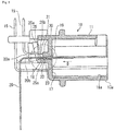
Figure 2 is a sectional view taken along lint II-II inFigure 1 ; -
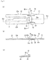
Figure 3 is views showing a terminal before assembled to a housing,Figure 3(a) being a plan view,Figure 3(b) being a sectional view taken along line IIIb-IIIb inFigure 3(a), and Figure 3(c) being a sectional view taken along line IIIc-IIIc inFigure 3(a) ; -
Figure 4 is views for explaining an action of a lance upon the terminal being press-fitted; and -
Figure 5 is views for explaining a second embodiment. - The present invention will be explained below in detail based upon embodiments shown in the accompanying figures.
- [First Embodiment] As shown in
Figure 1 andFigure 2 , aconnector 10 is provided with a plurality of tab-type terminals 20, a plurality of pin-type terminals 15, and ahousing 11 configured to be mutually mated with a mating connector (not shown) and holding theterminals 20 andterminals 15. Theconnector 10 is configured to hold theterminal 20 by only a housing lance (hereinafter, simply called "lance") 30. - [Housing 11] The
housing 11 is formed integrally by injection-molding insulating resin. Thehousing 11 is provided with afitting hood 13a configured to mate with a mating connector. Areceiving chamber 16 into which the mating connector is inserted from an opened front portion thereof is formed inside thefitting hood 13a. Thereceiving chamber 16 has a rear portion sectioned by adepth wall 17. A plurality of insertion holes 19 (two holes are shown inFigure 1 ) in which theterminal 20 is inserted are formed in thereception chamber 16a of thefitting hood 13a so as to penetrate the front and back of thedepth wall 17. Theinsertion hole 19 has alance 30 provided on an upper side thereof and a supportingwall 18 provided on a lower side thereof so as to face thelance 30. Thelance 30 and the supportingwall 18 are both formed integrally with thedepth wall 17, and project rearward. Incidentally, in theconnector 10, it is defined that a side thereof configured to mate with a mating connector (not shown) is a front side while an opposite side thereto is a rear side. Further, regarding "up" and "down", they correspond to an upper side and a lower side on the figures. Thehousing 11 is further provided withfitting hoods hoods fitting hood 13a and explanation thereof is omitted. Theterminal 20 and theterminal 15 are held by press-fitting them into thehousing 11, portions thereof are arranged inside thereception chamber 16, and the other portions thereof are arranged outside thehousing 11. Incidentally, theterminal 20 is used for power supply, while theterminal 15 is used for signal transmission. - [Lance 30] The
lance 30 is a cantilever member which prevents theterminal 20 from falling out from thehousing 11 unintentionally. Thelance 30 extends to a rear end side to be locked to theterminal 20. Thelance 30 is provided in an inclined manner so as to descend rearward. Thelance 30 comes in contact with alocking piece 25 of theterminal 20 to be pushed up in the process of inserting theterminal 20 to a predetermined position. When thelance 30 is inserted to a predetermined holding position, the pressing-up is released and alocking wall 31 at a front end of thelance 30 and alocking wall 25c of theterminal 20 face each other to be locked to each other, so that theterminal 20 is retained. Thelance 30 is set such that alower end position 33 of thelance 30 is higher than atop side 20a of theterminal 20 described later and it is lower than aflat portion 25b of thelocking piece 25 in a free state until thelance 30 comes in contact with thelocking piece 25. Incidentally, thelance 30 is made of insulating resin, and it is formed integrally with thehousing 11. - [Terminal 20] The
terminal 20 electrically connects a board and a mating connector with each other. As shown inFigure 3(a) , theterminal 20 is provided with a connectingportion 21 provided for connection with a terminal of the mating connector, atine portion 22 provided for connection with a board, and aholding portion 23 connecting the connectingportion 21 and thetine portion 22 with each other and provided for holding performed by thehousing 11. Theterminal 20 is integrally formed by stamping metal material excellent in electrical conductivity and elasticity, for example, a plate material made of copper alloy. - As shown in
Figure 3(b) , theholding portion 23 is provided with a through-hole 24 penetrating the top and bottom thereof, and thelocking piece 25 in this order from the connectingportion 21 side. The through-hole 24 and thelocking piece 25 are arranged at a central portion of theholding portion 23 in a widthwise direction X. Thelocking piece 25 is provided with aninclined portion 25a, theflat portion 25b, and alocking wall 25c. Theinclined portion 25a is formed so as to rise up from thetop side 20a of theterminal 20 forward. Further, theflat portion 25b is formed to communicate with theinclined portion 25a and be parallel to thetop side 20a. Thelocking wall 25c is formed so as to suspend from a front end of theflat portion 25b and be perpendicular to thetop side 20a. Incidentally, thelocking piece 25 is formed by cutting and raising a portion of a terminal. The locking piece (locking portion) can be formed integrally with the terminal by formation performed by cutting and raising a portion of the terminal without adding a special step. - Further, as shown in
Figure 3(c) , in the holdingportion 23, press-fittingprojections portion 23 in a widthwise direction thereof so as to sandwich the through-hole 24 and thelocking piece 25. The press-fittingprojections bottom side 20b of the terminal 20 in order to improve holding force due to press-fitting of the terminal 20 into thehousing 11 obtained by pressing of the press-fittingprojections wall 18 with a local pressure, and they are formed by performing pressing forming. In addition,tabs portion 23 in a widthwise direction X thereof. Thetabs housing 11 to hold the terminal 20 at a predetermined position of thehousing 11. - The
tine portion 22 is bifurcated from its middle to be provided with afirst tine 22a and asecond tine 22b. Thefirst tine 22a is folded to a lower side to be connected to a first board (not shown) arranged on a lower side of theconnector 10. Further, thesecond tine 22b is folded to an upper side to be connected to a second board (not shown) arranged on an upper side of theconnector 10. Incidentally, after the terminal 20 is assembled at the predetermined position of thehousing 11 in a flat state shown inFigure. 3 , thefirst tine 22a and thesecond tine 22b are folded as shown inFigure 1 andFigure 3 . Further, thefirst tine 22a and thesecond tine 22b are electrically connected and fixed to the first board and the second board by soldering process, respectively. In order to improve solder wettability, plating films made of the same metal as that of a main component (for example, tin) of the solder are applied to surfaces of thefirst tine 22a and thesecond tine 22b. Here, the terminal 20 is provided for power supply and the tine portion 22 (thefirst tine 22a and thesecond tine 22b) has a width corresponding to current caused to flow in order to allow flow of large current in thetine portion 22. If the width is narrow, the temperature of the terminal 20 may rise abnormally. - [Action of Lance 30] Next, an action of the
lance 30 in the process of press-fitting the terminal 20 into thehousing 11 will be explained with reference toFigure 4 . Incidentally, a movement of thelance 30 explained below is a movement relative to the terminal 20. As shown inFigure 4(a) , the terminal 20 in a flat state is inserted into theinsertion hole 19 of thehousing 11 from its front side rearward, as shown by arrow D. Since thelance 30 in the free state is provided at a position higher than thetop side 20a, the terminal 20 is inserted without contacting of the tine 22 (thetop side 20a) with thelance 30 until the lockingpiece 25 reaches thelance 30, as shown inFigure 4(a) . In the process of the insertion, thelance 30 moves to a movement region A shown inFigure 3(a) . That is, thelance 30 moves on a trajectory spaced upward from thetop side 20a (a lance passage side) of thesecond tine 22b. When further insertion of the terminal 20 is performed after thelocking piece 25 has reached thelance 30, as shown inFigure 4(b) , thelance 30 comes in contact with theinclined portion 25a and theflat portion 25b in this order and thelocking piece 25 passes through thelance 30 while pushing up thelance 30. When the terminal 20 is inserted to the predetermined position and thelocking piece 25 passes through thelance 30, thelance 30 returns to the free state elastically, so that the lockingwall 25c of the lockingpiece 25 and the lockingwall 31 of thelance 30 face each other, as shown inFigure 4(c) . Thus, the terminal 20 is retained by thelance 30. After the terminal 20 is inserted to the predetermined position and it is press-fitted into thehousing 11, thefirst tine 22a and thesecond tine 22b are folded to the lower side and the upper side, respectively, so that they are connected to the first board and the second board. - As explained above, in the
connector 10, the lockingwall 25c is provided at the lockingpiece 25 projecting from thetop side 20a of the terminal 20 (thesecond tine 22b) and thelance 30 is provided at such a position that thelance 30 is spaced from thetop side 20a of the terminal 20 while it interfaces with the lockingpiece 25. Therefore, in the insertion process of the terminal 20, thelance 30 moves relative to the terminal 20 (thetop side 20a) without coming in contact with the terminal 20 (thetop side 20a) until the lockingpiece 25 reaches thelance 30, and thereafter thelance 30 comes in contact with the lockingpiece 25. Therefore, according to theconnector 10, since it can be avoided that the plating applied to thetine portion 22 is scraped by thelance 30, the solder wettability can be secured. Further, even in a portion of thetine portion 22 which is not provided for soldering, a scraped scar occurring upon scraping is not preferable from the view point of appearance, but the scraped scar can be prevented from occurring according to theconnector 10. Incidentally, since the lockingpiece 25 is not soldered to the board and it is accommodated inside thehousing 11, even if it is scraped by thelance 30, the scraping is not problematic. - In addition, according to the
connector 10, a width required to allow flowing of large current in thesecond tine 22b of thetine portion 22 can be secured. That is, in order to avoid contact between thelance 30 and thesecond tine 22a, the movement region A of thesecond tine 22b shown inFigure 3(a) can be cut off. However, when the movement region A is cut off, the width of thesecond tine 22b becomes narrower correspondingly, so that a value of current which is allowed to flow is restricted. On the other hand, in theconnector 10, since contact between thelance 30 and thesecond tine 22a is avoided, it is unnecessary to narrow the width of thesecond tine 22b, so that the width of the tine portion 20 (thefirst tine 22a and thesecond tine 22b) can be set corresponding to large current. - Further, since the terminal 20 is pressed against the supporting
wall 18 via the press-fittingprojections housing 11 in a more stable state. Since the terminal 20 can be held in the stable state, the terminal 20 is prevented from falling out by providing thelance 30 only on one side. Incidentally, in this embodiment, though thelance 30 is provided on the upper side, it may be provided on the lower side. In this case, a similar effect can be achieved by using the terminal 20 in a reversed state. - [Second Embodiment] In the first embodiment, the means for preventing the
second tine 22b from being scraped by thelance 30 by causing the lockingpiece 25 to project from thetop side 22a of the terminal 20 (thesecond tine 22b) has been explained. The present invention has the gist that a portion locking thelance 30 has been raised relative to thetop side 20a. Though the first embodiment is configured such that the portion to be locked by thelance 30 is caused to project relative to thetop side 20a, means for recessing thetop side 20a relative to the locking portion will be explained in the second embodiment contrary to the first embodiment. Portions of this embodiment different from those of the first embodiment will be mainly explained below. Incidentally, same reference signs are attached to same constituent portions as those of the first embodiment and explanation thereof is omitted. As shown inFigure 5 , a terminal 40 according to the second embodiment is formed with a groove 41 (a lance passage side) in a region corresponding to the trajectory of passage of thelance 30 upon inserting the terminal 40. Thegroove 41 is formed on thetop side 20a of thesecond tine 22b, and a depth and a width thereof are set such that thelance 30 in a free state does not interfere with the terminal 40 upon inserting the terminal 40. The second embodiment is not provided with the lockingpiece 25 and it is configured such that thelance 30 is locked to a lockingwall 44 composed of an inner wall defining a lockinghole 43 penetrating the top and bottom of the holdingportion 23. Incidentally, a forming method of thegroove 41 is arbitrary, and thegroove 41 can be formed by stamping process or cutting process. The terminal 40 shown inFigure 5 is one obtained by the stamping process, and thebottom side 20b of thesecond tine 22b pressed is caused to project downward relative to the other portion of thesecond tine 22b, as shown inFigure 5(b) and Figure 5(c) . - In the process of press-fitting the terminal 40 into the
housing 11, thelance 30 passes through thesecond tine 22b without coming in contact with thesecond tine 22b because thegroove 41 is formed. Therefore, a movement trajectory of thelance 30 is formed at a position facing a bottom face of thegroove 41. Then, when thelance 30 reaches a region B of thetop side 20a which is not formed with thegroove 41, it rides on the region B, and when thelance 30 further moves, it drops in the lockinghole 43 to be locked to the lockingwall 44. - In addition to that an advantageous effect similar to that in the first embodiment can be achieved even in the second embodiment, it is unnecessary to change molding for the
housing 11 especially because the above-described advantageous effect can be achieved by only forming thegroove 41 in the terminal 40 without changing the position of theconventional lance 30. - Though the embodiments of the present invention have been explained above, it is possible to select the constitutions described in the above-described embodiments or change these constitutions to other constitutions without departing from the gist of the present invention.
-
- 10
- connector
- 11
- housing
- 13a to 13c
- fitting hood
- 15
- terminal
- 16
- receiving chamber
- 16a
- receiving chamber
- 17
- depth wall
- 18
- supporting wall
- 19
- insertion hole
- 20
- terminal
- 20a
- top side
- 20b
- bottom side
- 21
- connecting portion
- 22
- tine portion
- 22a
- first tine
- 22b
- second tine
- 23
- holding portion
- 24
- through-hole
- 25
- locking piece
- 25a
- inclined portion
- 25b
- flat portion
- 25c
- locking wall
- 28
- press-fitting projection
- 29
- tab
- 30
- lance
- 31
- locking wall
- 33
- lower end position
- 40
- terminal
- 41
- groove
- 43
- locking hole
- 44
- locking wall
Claims (5)
- An electric connector terminal locked by a lance provided in a housing, characterized in that
the terminal comprises:a lance passage side facing, in a process of being fitted into the housing, a trajectory of a relative movement of the lance; anda locking portion provided forward in a direction of the relative movement of the lance beyond the lance passage side and locked by the lance, whereinthe locking portion is raised from the lance passage side. - The electric connector terminal according to claim 1, wherein
the terminal comprises a tine for power supply, and
the lance passage side is provided on the tine which is applied with plating. - The electric connector terminal according to claim 1, wherein
the locking portion is a locking piece projecting beyond the lance passage side by cutting and raising. - An electric connector comprising:a terminal configured to be electrically connected to a mating terminal; anda housing holding the terminal and provided with a lance locking the terminal, characterized in that the terminal is the terminal according to any one of claims 1 to 3.
- The electric connector according to claim 4, wherein
the lance is provided at a position spaced from the lance passage side and interfering with the locking portion.
Applications Claiming Priority (2)
| Application Number | Priority Date | Filing Date | Title |
|---|---|---|---|
| JP2013186389A JP2015053226A (en) | 2013-09-09 | 2013-09-09 | Terminal of electric connector, and electric connector |
| PCT/JP2014/073708 WO2015034092A1 (en) | 2013-09-09 | 2014-09-08 | Electric connector terminal, and electric connector |
Publications (2)
| Publication Number | Publication Date |
|---|---|
| EP3046184A1 true EP3046184A1 (en) | 2016-07-20 |
| EP3046184A4 EP3046184A4 (en) | 2017-04-12 |
Family
ID=52628549
Family Applications (1)
| Application Number | Title | Priority Date | Filing Date |
|---|---|---|---|
| EP14842602.6A Withdrawn EP3046184A4 (en) | 2013-09-09 | 2014-09-08 | Electric connector terminal, and electric connector |
Country Status (5)
| Country | Link |
|---|---|
| US (1) | US9923296B2 (en) |
| EP (1) | EP3046184A4 (en) |
| JP (1) | JP2015053226A (en) |
| CN (1) | CN105518943A (en) |
| WO (1) | WO2015034092A1 (en) |
Families Citing this family (13)
| Publication number | Priority date | Publication date | Assignee | Title |
|---|---|---|---|---|
| JP7197996B2 (en) * | 2018-04-26 | 2022-12-28 | ヒロセ電機株式会社 | electrical connector |
| JP2021168227A (en) * | 2018-07-25 | 2021-10-21 | アルプスアルパイン株式会社 | Press-fit terminal holding structure and connector |
| US11973286B2 (en) * | 2020-06-01 | 2024-04-30 | Amphenol Commercial Products (Chengdu) Co., Ltd. | Electrical connector and manufacturing method thereof |
| CN114597707A (en) | 2020-12-04 | 2022-06-07 | 安费诺商用电子产品(成都)有限公司 | Card edge connector with locking system |
| US12431644B2 (en) | 2021-09-24 | 2025-09-30 | Amphenol Commercial Products (Chengdu) Co., Ltd. | Electrical connector for compact system |
| CN216413342U (en) * | 2021-10-26 | 2022-04-29 | 泰科电子(上海)有限公司 | Connector |
| CN216488833U (en) | 2021-10-27 | 2022-05-10 | 安费诺商用电子产品(成都)有限公司 | electrical connector |
| TWM646552U (en) | 2021-11-22 | 2023-10-01 | 大陸商安費諾商用電子產品(成都)有限公司 | Latch assemblies and related electrical connectors and electronic systems |
| JP7622617B2 (en) * | 2021-11-26 | 2025-01-28 | 住友電装株式会社 | connector |
| US12463363B2 (en) | 2021-12-06 | 2025-11-04 | Amphenol Commercial Products (Chengdu) Co., Ltd. | Reliable electrical connector |
| JP7574808B2 (en) * | 2022-01-18 | 2024-10-29 | 住友電装株式会社 | connector |
| US12586941B2 (en) | 2022-01-27 | 2026-03-24 | Amphenol Commercial Products (Chengdu) Co., Ltd. | Field installable card edge connector |
| TW202408092A (en) | 2022-04-18 | 2024-02-16 | 大陸商安費諾商用電子產品(成都)有限公司 | Reliable, robust card edge connector |
Family Cites Families (26)
| Publication number | Priority date | Publication date | Assignee | Title |
|---|---|---|---|---|
| US3530429A (en) * | 1968-06-14 | 1970-09-22 | Amp Inc | Electrical tab connector |
| JPS496547Y1 (en) * | 1969-11-06 | 1974-02-15 | ||
| JPS496547B1 (en) | 1970-08-27 | 1974-02-14 | ||
| GB1431047A (en) | 1972-05-09 | 1976-04-07 | Gist Brocades Nv | Packaging of materials |
| JPS524543Y2 (en) * | 1972-07-19 | 1977-01-29 | ||
| US4114975A (en) * | 1977-07-20 | 1978-09-19 | Amp Incorporated | Displation type electrical connector |
| JPS55144774U (en) * | 1979-04-03 | 1980-10-17 | ||
| JPS5756470Y2 (en) * | 1979-05-25 | 1982-12-04 | ||
| JPS56127681U (en) * | 1980-02-29 | 1981-09-29 | ||
| JPS6214605Y2 (en) * | 1980-05-16 | 1987-04-14 | ||
| JPS605514Y2 (en) * | 1980-11-14 | 1985-02-20 | 日産自動車株式会社 | electrical connectors |
| US5102356A (en) * | 1991-05-24 | 1992-04-07 | Amp Incorporated | Electrical connector having board retention means |
| US5139446A (en) * | 1991-10-30 | 1992-08-18 | Amp Incorporated | Electrical connector assembly |
| JP3145452B2 (en) * | 1991-12-27 | 2001-03-12 | ミネソタ マイニング アンド マニュファクチャリング カンパニー | Connector with contact fixing means |
| US5658168A (en) * | 1995-03-13 | 1997-08-19 | The Whitaker Corporation | Single piece pin contact |
| JP2003297490A (en) * | 2002-04-08 | 2003-10-17 | Sumitomo Wiring Syst Ltd | Connector |
| JP2004047323A (en) * | 2002-07-12 | 2004-02-12 | Sumitomo Wiring Syst Ltd | Connector for board |
| DE602004023105D1 (en) | 2003-10-28 | 2009-10-22 | Vertex Pharma | PREPARATION OF 4,5-DIALKYL-3-ACYLPYRROL-2-CARBON CONNECTING ACYLATION |
| JP2005353371A (en) * | 2004-06-09 | 2005-12-22 | Tyco Electronics Amp Kk | Terminal press fit structure |
| JP2006344458A (en) * | 2005-06-08 | 2006-12-21 | Hirose Electric Co Ltd | Surface mount type electrical connector |
| DK2482891T3 (en) | 2009-09-30 | 2017-02-06 | Sanofi Aventis Deutschland | RETRIEVABLE DRIVING AND PHARMACEUTICAL SUPPLY |
| JP5378144B2 (en) | 2009-10-15 | 2013-12-25 | タイコエレクトロニクスジャパン合同会社 | Electrical connector assembly |
| JP2011187412A (en) * | 2010-03-11 | 2011-09-22 | Sumitomo Wiring Syst Ltd | Mounting board, and manufacturing method thereof |
| JP5786275B2 (en) | 2010-03-23 | 2015-09-30 | セイコーエプソン株式会社 | Power supply control circuit |
| JP5628653B2 (en) * | 2010-12-13 | 2014-11-19 | 日本圧着端子製造株式会社 | PCB connector |
| US9407047B1 (en) * | 2015-05-28 | 2016-08-02 | Delphi Technologies Inc. | Electrical connector assembly |
-
2013
- 2013-09-09 JP JP2013186389A patent/JP2015053226A/en active Pending
-
2014
- 2014-09-08 WO PCT/JP2014/073708 patent/WO2015034092A1/en not_active Ceased
- 2014-09-08 CN CN201480049677.2A patent/CN105518943A/en active Pending
- 2014-09-08 EP EP14842602.6A patent/EP3046184A4/en not_active Withdrawn
-
2016
- 2016-03-09 US US15/064,912 patent/US9923296B2/en active Active
Non-Patent Citations (1)
| Title |
|---|
| See references of WO2015034092A1 * |
Also Published As
| Publication number | Publication date |
|---|---|
| EP3046184A4 (en) | 2017-04-12 |
| US9923296B2 (en) | 2018-03-20 |
| JP2015053226A (en) | 2015-03-19 |
| WO2015034092A1 (en) | 2015-03-12 |
| US20160190724A1 (en) | 2016-06-30 |
| CN105518943A (en) | 2016-04-20 |
Similar Documents
| Publication | Publication Date | Title |
|---|---|---|
| EP3046184A1 (en) | Electric connector terminal, and electric connector | |
| US9461415B2 (en) | Electrical connector with new assembling method | |
| US9912106B2 (en) | Electrical connector having improved shielding shell | |
| US9847604B2 (en) | Electrical connector having improved shielding structure | |
| US10998655B2 (en) | Connector and connection system | |
| US11158967B2 (en) | Board-to-board electrical connector with lock disengageable by an operation portion | |
| US7488198B2 (en) | Electrical connector with improved terminals | |
| US20130337692A1 (en) | Electrical connector for connecting to cables | |
| JP2012049015A (en) | Electric connector | |
| CN106469864A (en) | Circuit board use adapter | |
| US20150111437A1 (en) | Connector terminal | |
| US9425558B1 (en) | Electrical connector having an outer shielding covered by a cover with a resilient plate extending upward and rearward | |
| JP2008041664A (en) | connector | |
| US9905960B2 (en) | Electrical connector | |
| US8870606B2 (en) | Electrical connector for connecting to cables | |
| CN102064402B (en) | Electronic element and method for assembling electronic element and circuit board | |
| US20100068940A1 (en) | Electrical connector having auxiliary hold-down arrangement | |
| CN101258646A (en) | Board-to-board connector and connector pair | |
| JP2012084501A (en) | Electric connector | |
| US7699662B1 (en) | Electrical connector | |
| US9153906B1 (en) | Socket connector | |
| KR101586250B1 (en) | Board to board connector | |
| US11824296B2 (en) | Terminal, connector and connector assembly | |
| JP6651393B2 (en) | IDC contacts and IDC connectors | |
| JP2016021330A (en) | Terminal fittings and connectors |
Legal Events
| Date | Code | Title | Description |
|---|---|---|---|
| PUAI | Public reference made under article 153(3) epc to a published international application that has entered the european phase |
Free format text: ORIGINAL CODE: 0009012 |
|
| 17P | Request for examination filed |
Effective date: 20160405 |
|
| AK | Designated contracting states |
Kind code of ref document: A1 Designated state(s): AL AT BE BG CH CY CZ DE DK EE ES FI FR GB GR HR HU IE IS IT LI LT LU LV MC MK MT NL NO PL PT RO RS SE SI SK SM TR |
|
| AX | Request for extension of the european patent |
Extension state: BA ME |
|
| DAX | Request for extension of the european patent (deleted) | ||
| A4 | Supplementary search report drawn up and despatched |
Effective date: 20170313 |
|
| RIC1 | Information provided on ipc code assigned before grant |
Ipc: H01R 13/422 20060101AFI20170307BHEP |
|
| 17Q | First examination report despatched |
Effective date: 20180115 |
|
| RIC1 | Information provided on ipc code assigned before grant |
Ipc: H01R 13/422 20060101AFI20191015BHEP Ipc: H01R 12/72 20110101ALN20191015BHEP Ipc: H01R 13/03 20060101ALI20191015BHEP |
|
| STAA | Information on the status of an ep patent application or granted ep patent |
Free format text: STATUS: THE APPLICATION IS DEEMED TO BE WITHDRAWN |
|
| 18D | Application deemed to be withdrawn |
Effective date: 20200603 |