EP3046019B1 - Electronic device and operating method thereof - Google Patents
Electronic device and operating method thereof Download PDFInfo
- Publication number
- EP3046019B1 EP3046019B1 EP16151717.2A EP16151717A EP3046019B1 EP 3046019 B1 EP3046019 B1 EP 3046019B1 EP 16151717 A EP16151717 A EP 16151717A EP 3046019 B1 EP3046019 B1 EP 3046019B1
- Authority
- EP
- European Patent Office
- Prior art keywords
- touch
- processor
- display screen
- edge area
- display
- Prior art date
- Legal status (The legal status is an assumption and is not a legal conclusion. Google has not performed a legal analysis and makes no representation as to the accuracy of the status listed.)
- Active
Links
Images












Classifications
-
- G—PHYSICS
- G06—COMPUTING OR CALCULATING; COUNTING
- G06F—ELECTRIC DIGITAL DATA PROCESSING
- G06F3/00—Input arrangements for transferring data to be processed into a form capable of being handled by the computer; Output arrangements for transferring data from processing unit to output unit, e.g. interface arrangements
- G06F3/01—Input arrangements or combined input and output arrangements for interaction between user and computer
- G06F3/03—Arrangements for converting the position or the displacement of a member into a coded form
- G06F3/041—Digitisers, e.g. for touch screens or touch pads, characterised by the transducing means
- G06F3/0416—Control or interface arrangements specially adapted for digitisers
-
- G—PHYSICS
- G06—COMPUTING OR CALCULATING; COUNTING
- G06F—ELECTRIC DIGITAL DATA PROCESSING
- G06F3/00—Input arrangements for transferring data to be processed into a form capable of being handled by the computer; Output arrangements for transferring data from processing unit to output unit, e.g. interface arrangements
- G06F3/01—Input arrangements or combined input and output arrangements for interaction between user and computer
- G06F3/048—Interaction techniques based on graphical user interfaces [GUI]
- G06F3/0487—Interaction techniques based on graphical user interfaces [GUI] using specific features provided by the input device, e.g. functions controlled by the rotation of a mouse with dual sensing arrangements, or of the nature of the input device, e.g. tap gestures based on pressure sensed by a digitiser
- G06F3/0488—Interaction techniques based on graphical user interfaces [GUI] using specific features provided by the input device, e.g. functions controlled by the rotation of a mouse with dual sensing arrangements, or of the nature of the input device, e.g. tap gestures based on pressure sensed by a digitiser using a touch-screen or digitiser, e.g. input of commands through traced gestures
-
- G—PHYSICS
- G06—COMPUTING OR CALCULATING; COUNTING
- G06F—ELECTRIC DIGITAL DATA PROCESSING
- G06F3/00—Input arrangements for transferring data to be processed into a form capable of being handled by the computer; Output arrangements for transferring data from processing unit to output unit, e.g. interface arrangements
- G06F3/01—Input arrangements or combined input and output arrangements for interaction between user and computer
- G06F3/048—Interaction techniques based on graphical user interfaces [GUI]
- G06F3/0487—Interaction techniques based on graphical user interfaces [GUI] using specific features provided by the input device, e.g. functions controlled by the rotation of a mouse with dual sensing arrangements, or of the nature of the input device, e.g. tap gestures based on pressure sensed by a digitiser
- G06F3/0488—Interaction techniques based on graphical user interfaces [GUI] using specific features provided by the input device, e.g. functions controlled by the rotation of a mouse with dual sensing arrangements, or of the nature of the input device, e.g. tap gestures based on pressure sensed by a digitiser using a touch-screen or digitiser, e.g. input of commands through traced gestures
- G06F3/04883—Interaction techniques based on graphical user interfaces [GUI] using specific features provided by the input device, e.g. functions controlled by the rotation of a mouse with dual sensing arrangements, or of the nature of the input device, e.g. tap gestures based on pressure sensed by a digitiser using a touch-screen or digitiser, e.g. input of commands through traced gestures for inputting data by handwriting, e.g. gesture or text
-
- G—PHYSICS
- G06—COMPUTING OR CALCULATING; COUNTING
- G06F—ELECTRIC DIGITAL DATA PROCESSING
- G06F3/00—Input arrangements for transferring data to be processed into a form capable of being handled by the computer; Output arrangements for transferring data from processing unit to output unit, e.g. interface arrangements
- G06F3/01—Input arrangements or combined input and output arrangements for interaction between user and computer
- G06F3/017—Gesture based interaction, e.g. based on a set of recognized hand gestures
-
- G—PHYSICS
- G06—COMPUTING OR CALCULATING; COUNTING
- G06F—ELECTRIC DIGITAL DATA PROCESSING
- G06F3/00—Input arrangements for transferring data to be processed into a form capable of being handled by the computer; Output arrangements for transferring data from processing unit to output unit, e.g. interface arrangements
- G06F3/01—Input arrangements or combined input and output arrangements for interaction between user and computer
- G06F3/03—Arrangements for converting the position or the displacement of a member into a coded form
- G06F3/041—Digitisers, e.g. for touch screens or touch pads, characterised by the transducing means
- G06F3/0412—Digitisers structurally integrated in a display
-
- G—PHYSICS
- G06—COMPUTING OR CALCULATING; COUNTING
- G06F—ELECTRIC DIGITAL DATA PROCESSING
- G06F3/00—Input arrangements for transferring data to be processed into a form capable of being handled by the computer; Output arrangements for transferring data from processing unit to output unit, e.g. interface arrangements
- G06F3/01—Input arrangements or combined input and output arrangements for interaction between user and computer
- G06F3/048—Interaction techniques based on graphical user interfaces [GUI]
- G06F3/0487—Interaction techniques based on graphical user interfaces [GUI] using specific features provided by the input device, e.g. functions controlled by the rotation of a mouse with dual sensing arrangements, or of the nature of the input device, e.g. tap gestures based on pressure sensed by a digitiser
- G06F3/0488—Interaction techniques based on graphical user interfaces [GUI] using specific features provided by the input device, e.g. functions controlled by the rotation of a mouse with dual sensing arrangements, or of the nature of the input device, e.g. tap gestures based on pressure sensed by a digitiser using a touch-screen or digitiser, e.g. input of commands through traced gestures
- G06F3/04886—Interaction techniques based on graphical user interfaces [GUI] using specific features provided by the input device, e.g. functions controlled by the rotation of a mouse with dual sensing arrangements, or of the nature of the input device, e.g. tap gestures based on pressure sensed by a digitiser using a touch-screen or digitiser, e.g. input of commands through traced gestures by partitioning the display area of the touch-screen or the surface of the digitising tablet into independently controllable areas, e.g. virtual keyboards or menus
-
- G—PHYSICS
- G06—COMPUTING OR CALCULATING; COUNTING
- G06F—ELECTRIC DIGITAL DATA PROCESSING
- G06F3/00—Input arrangements for transferring data to be processed into a form capable of being handled by the computer; Output arrangements for transferring data from processing unit to output unit, e.g. interface arrangements
- G06F3/16—Sound input; Sound output
-
- G—PHYSICS
- G06—COMPUTING OR CALCULATING; COUNTING
- G06F—ELECTRIC DIGITAL DATA PROCESSING
- G06F2200/00—Indexing scheme relating to G06F1/04 - G06F1/32
- G06F2200/16—Indexing scheme relating to G06F1/16 - G06F1/18
- G06F2200/163—Indexing scheme relating to constructional details of the computer
- G06F2200/1637—Sensing arrangement for detection of housing movement or orientation, e.g. for controlling scrolling or cursor movement on the display of an handheld computer
-
- G—PHYSICS
- G06—COMPUTING OR CALCULATING; COUNTING
- G06F—ELECTRIC DIGITAL DATA PROCESSING
- G06F2203/00—Indexing scheme relating to G06F3/00 - G06F3/048
- G06F2203/041—Indexing scheme relating to G06F3/041 - G06F3/045
- G06F2203/04104—Multi-touch detection in digitiser, i.e. details about the simultaneous detection of a plurality of touching locations, e.g. multiple fingers or pen and finger
Definitions
- the present disclosure relates to an electronic device and an operating method thereof. More specifically, the present disclosure relates to an electronic device that has a display that includes a main area and an edge area extending from the main area, and a method of operating the same.
- electronic devices have various functions added thereto and perform these functions in combination.
- electronic devices may perform mobile communication functions, data communication functions, data output functions, data storage functions, image photographing functions, audio recording functions, etc.
- Such electronic devices include a display and an input device.
- the display and the input device may be coupled to each other so as to be implemented as a touchscreen.
- the electronic devices may output display screens through the touchscreen.
- the electronic devices may control the display screens by detecting touches on the touchscreen.
- US 2012/304133 A1 discloses a device with a flat touch screen. A touch dragged from an edge portion to the main area of the screen is used to invoke a new window or screen.
- an aspect of the present disclosure is to provide an electronic device that has a display that includes a main area and an edge area extending from the main area, and a method of operating the same.
- a method of operating an electronic device includes outputting a display screen on a display that has a main area and an edge area extending from an edge of the main area, when detecting a touch, determining a location of the touch in one of the main area and the edge area, and controlling the display screen according to the location of the touch.
- an electronic device in accordance with another aspect of the present disclosure, includes a display including a main area and an edge area extending from an edge of the main area, and configured to output a display screen in at least one of the main area and the edge area, an input device configured to detect a touch, a determination unit configured to determine a location of the touch in one of the main area and the edge area when the touch is detected, and a processor configured to control the display screen according to the location of the touch.
- the display includes not only the main area but also the edge area. This can create a touch motion that is generated from not only the main area but also the edge area in the screen control device. Accordingly, the screen control device can provide various interactions for various touch motions. Namely, the screen control device can control the display screen in response to various touch motions. Therefore, the screen control device can enhance use efficiency and user convenience of the electronic device.
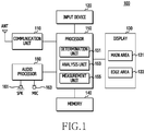
- FIG. 1 is a block diagram of an electronic device according to an embodiment of the present disclosure.
- FIG. 2 illustrates implemented examples of the electronic device according to an embodiment of the present disclosure.
- view (a) of FIG. 2 is a plan view of the electronic device
- views (b) to (e) are cross-sectional views taken along line A-A' of view (a) of FIG. 2 .
- the electronic device 100 of this embodiment of the present disclosure includes a communication unit 110, an input device 120, a display 130, a memory 140, a processor 150, and an audio processor 160.
- the communication unit 110 performs communication in the electronic device 100.
- the communication unit 110 may communicate with an external device (not illustrated) in various communication schemes.
- the communication unit 110 may perform at least one of wireless communication and wired communication.
- the communication unit 110 may connect to at least one of a mobile communication network and a data communication network.
- the communication unit 110 may perform short range communication.
- the external device may include an electronic device, a base station, a server, and a satellite.
- the communication schemes may include long term evolution (LTE), wideband code division multiple access (WCDMA), global system for mobile communications (GSM), Wi-Fi, Bluetooth, and near field communications (NFC).
- LTE long term evolution
- WCDMA wideband code division multiple access
- GSM global system for mobile communications
- Wi-Fi Wi-Fi
- Bluetooth and near field communications
- the input device 120 generates input data in the electronic device 100.
- the input device 120 may generate the input data in response to a user input of the electronic device 100.
- the input device 120 may include at least one input means.
- the input device 120 may include a key pad, a dome switch, a physical button, a touch panel, a jog & shuttle, and a sensor.
- the display 130 outputs a display screen.
- the display screen may include at least one of an image and a text.
- the display 130 may include a liquid crystal display (LCD), a light emitting diode (LED) display, an organic LED (OLED) display, a micro electro mechanical system (MEMS) display, or an electronic paper display.
- the display 130 may include a plurality of light emitting diodes.
- the display 130 may be coupled with the input device 120 so as to be implemented as a touchscreen.
- the display 130 may include a main area 131 and an edge area 133.
- the main area 131 and the edge area 133 may output a display screen.
- the display screen may be output in parts by the main area 131 and the edge area 133.
- the main area 131 may output the whole display screen.
- the edge area 133 may output color light.
- the main area 131 is disposed on the front side of the electronic device 100.
- the edge area 133 extends from an edge of the main area 131.
- the edge area 133 may extend from at least one of the upper, lower, left and right sides of the main area 131.
- the edge area 133 may be integrally formed with the main area 131.
- the main area 131 and the edge area 133 may be formed of a flat surface.
- the main area 131 and the edge area 133 may be disposed on the same plane. In this way, the edge area 133 may be disposed on the front side of the electronic device 100.
- the edge area 133 may be inclined with respect to the main area 131. In other words, the edge area 133 may extend from the main area 131 toward the rear side of the electronic device 100. In this way, the edge area 133 may be disposed on the lateral side of the electronic device 100.
- the main area 131 and the edge area 133 may be formed of a curved surface.
- the main area 131 may be formed of a flat plane, and the edge area 133 may be formed of a curved surface.
- the main area 131 may be formed of a curved surface, and the edge area 133 may be formed of a flat plane.
- the main area 131 and the edge area 133 may be formed of a single curved surface.
- the main area 131 and the edge area 133 may be formed of different curved surfaces.
- the edge area 133 may be inclined with respect to the main area 131. In other words, the edge area 133 may extend from the main area 131 toward the rear side of the electronic device 100. The edge area 133 may be disposed on the lateral side of the electronic device 100.
- the display 130 may be manufactured to have flexibility and may then be bent. In this case, the display 130 may be partially bent.
- the display 130 is bent or curved so that the edge area 133 may be inclined with respect to the main area 131.
- the display 130 may be bent or curved with respect to the border between the main area 131 and the edge area 133.
- the display 130 may be formed of a curved surface.
- one of the main area 131 and the edge area 133 may be curved, and the main area 131 and the edge area 133 may also be curved to have different curvatures.
- the display 130 may be bent on the whole.
- the main area 131 and the edge area 133 may be integrally curved. In other words, the main area 131 and the edge area 133 may be curved to have the same curvature.
- the memory 140 stores operating programs of the electronic device 100.
- the memory 140 may store a program for controlling a display screen according to a user input. Further, the memory 140 stores data generated while the programs are executed. In addition, the memory 140 stores functions for controlling a display screen. In this case, the memory 140 may match touch events and the functions and then store them.
- the processor 150 controls an overall operation in the electronic device 100. In this case, the processor 150 performs various functions. Further, the processor 150 controls the display 130 to output a display screen. In addition, the processor 150 controls a display screen. Here, the processor 150 may control the main area 131 and the edge area 133 separately, or by making an association therebetween. Besides, the processor 150 may detect a user input through the input device 120 to correspond to the main area 131 and the edge area 133. Namely, the processor 150 may detect a touch through the input device 120. In addition, the processor 150 may determine a touch event. Here, the processor 150 may determine the touch event according to at least one of a touch location and a touch motion. In this way, the processor 150 may control a display screen in response to the touch event.
- the processor 150 may include a determination unit 151, an analysis unit 153, and a measurement unit 155. Accordingly, the processor 150 may perform any of the operations described herein as being performed by the determination unit 151, the analysis unit 153, and the measurement unit 155. Further, one or more of the determination unit 151, the analysis unit 153, and the measurement unit 155 may be included in another processor or as at least one component separate from the processor 150.
- the determination unit 151 may detect the location of a touch.
- the determination unit 151 may detect the detection time of the touch location, together with the touch location.
- the determination unit 151 may detect the touch location as coordinates.
- the determination unit 151 may detect a plurality of coordinates in the area of the touch and may select one of the coordinates to determine the same as the touch location. To this end, if there is a space in the area of the touch, the determination unit 151 may divide the area of the touch. Further, the determination unit 151 may detect the touch location as positive (+) coordinates in the main area 131 and as negative (-) coordinates in the edge area 133. In this way, the processor 150 may control a display screen in response to the touch location.
- the determination unit 151 may determine an initial touch location on the display 130.
- the initial touch location may represent the location where the touch was first generated. Namely, the determination unit 151 may determine the initial touch location in one of the main area 131 and the edge area 133. In this way, the processor 150 may control a display screen according to the initial touch location.
- the analysis unit 153 may analyze a touch location. In this case, the analysis unit 153 may identify the detection time of the touch location. Further, the analysis unit 153 may detect the number of touch locations based on the detection time. Here, the analysis unit 153 may identify a single touch location and may also identify a plurality of touch locations based on the detection time. Namely, a plurality of simultaneously generated touch locations may be detected by the analysis unit 153. In this way, the processor 150 may control a display screen according to the number of touch locations. Besides, the analysis unit 153 may analyze the arrangement structure of the plurality of touch locations. In this way, the processor 150 may control a display screen according to the arrangement structure of the plurality of touch locations.
- the measurement unit 155 may track a touch motion. In this case, in response to the movement of the touch, the measurement unit 155 may measure the moving direction, the moving path, and the moving distance of the touch. In this way, the processor 150 may control a display screen according to the movement of the touch. Further, the measurement unit 155 may measure the detection time of the touch. Here, the detection time of the touch may represent the maintenance time of the touch at the same location. In this way, the processor 150 may control a display screen according to the detection time of the touch. In addition, the measurement unit 155 may measure the number of repeated touches. Here, the number of repeated touches may represent the number of times that a touch is detected at the same location. In this way, the processor 150 may control a display screen according to the number of repeated touches.
- the audio processor 160 processes an audio signal.
- the audio processor 160 includes a speaker (SPK) 161 and a microphone (MIC) 163. Namely, the audio processor 160 may reproduce an audio signal output from the processor 150 through the SPK 161. Further, the audio processor 160 may forward, to the processor 150, an audio signal generated by the MIC 163.
- SPK speaker
- MIC microphone
- FIG. 3 is a flowchart illustrating a procedure of a screen control method according to an embodiment of the present disclosure.
- FIGS. 9A to 30B illustrate examples for explaining the screen control method according to various embodiments of the present disclosure.
- the procedure of the screen control method starts by outputting a display screen 310 by the processor 150 in operation 211.
- the processor 150 outputs the display screen 310 through the display 130 to correspond to a current function.
- the processor 150 may activate both the main area 131 and the edge area 133.
- the processor 150 may output split screens, into which the display screen 310 is split, in the main area 131 and the edge area 133.
- the processor 150 may output the display screen 310 in the main area 131.
- the processor 150 may activate the input device 120 to correspond to the main area 131 and the edge area 133.
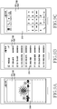
- the processor 150 may output the display screen 310 as illustrated in FIGS. 9A to 9C .
- the processor 150 may display an image on the display screen 310 as illustrated in FIG. 9A in response to an image display function.
- the processor 150 may display a list of received messages on the display screen 310 as illustrated in FIG. 9B in response to a received-message display function.
- the processor 150 may display the list of received messages on the display screen 310 as illustrated in FIG. 9B .
- the processor 150 may display a numeric keypad for call origination on the display screen 310 as illustrated in FIG. 9C in response to a call origination function.
- the processor 150 may display the numeric keypad for call origination on the display screen 310 as illustrated in FIG. 9C .
- the processor 150 detects the touch in operation 213.
- the processor 150 may detect the touch through the input device 120. Further, the processor 150 detects the location of the touch in operation 215. Namely, the processor 150 detects an initial touch location.
- the determination unit 151 may detect the location of the touch.
- the determination unit 151 may detect the detection time of the touch location, together with the touch location.
- the determination unit 151 may detect the touch location as coordinates.
- the determination unit 151 may detect a plurality of coordinates in the area of the touch and may select one of the coordinates to determine the same as the touch location. Further, the determination unit 151 may detect the touch location as positive (+) coordinates in the main area 131 and as negative (-) coordinates in the edge area 133.
- the processor 150 may detect a single touch location and may also simultaneously detect a plurality of touch locations. Namely, if there is a space in the area of the touch, the determination unit 151 may divide the touch area into a plurality of partial areas based on the space. The determination unit 151 may detect touch locations in the respective partial areas. In other words, the determination unit 151 may detect each of the touch locations as coordinates.
- the processor 150 determines whether the touch location is within the main area 131. Namely, the processor 150 determines whether the initial touch location is within the main area 131.
- the processor 150 determines a touch event in operation 219. Namely, the processor 150 determines the touch event to correspond to the main area 131.
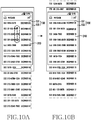
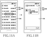
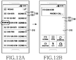
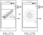
- the processor 150 may determine the touch event according to at least one of the touch location and the touch motion. For example, the processor 150 may determine a touch event from the movement of a touch as illustrated in FIGS. 10A and 10B , 11A and 11B , or 12A and 12B . Alternatively, the processor 150 may determine a touch event from the detection time of a touch as illustrated in FIGS. 19A and 19B , or 20A and 20B . In another case, the processor 150 may determine a touch event from the number of repeated touches as illustrated in FIGS. 23A and 23B , or 24A and 23B . In yet another case, the processor 150 may determine a touch event from the number of touch locations as illustrated in FIGS. 27A and 27B .
- the analysis unit 153 may analyze the touch location. Further, the measurement unit 155 may track the touch motion.
- the procedure of determining the touch event by the processor 150 to correspond to the main area 131 will be described below in more detail with reference to FIGS. 4 to 7 .
- the processor 150 determines whether the touch location is within the edge area 133 in operation 221. Namely, the processor 150 determines whether the initial touch location is within the edge area 133.
- the processor 150 determines a touch event in operation 223. Namely, the processor 150 determines the touch event to correspond to the edge area 133.
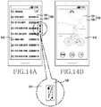
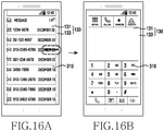
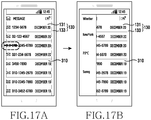
- the processor 150 may determine the touch event according to at least one of the touch location and the touch motion. For example, the processor 150 may determine a touch event from the movement of a touch as illustrated in FIGS. 13A and 13B , 14A and 14B , 15A and 15B , 16A and 16B , 17A and 17B , or 18A and 18B . Alternatively, the processor 150 may determine a touch event from the detection time of a touch as illustrated in FIGS. 21A and 21B , or 22A and 22B . In another case, the processor 150 may determine a touch event from the number of repeated touches as illustrated in FIGS. 25A and 25B , or 26A and 26B .
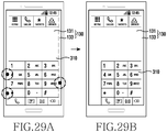
- the processor 150 may determine a touch event from the number of touch locations as illustrated in FIGS. 28A and 28B . In yet another case, the processor 150 may determine a touch event from the arrangement structure of touch locations as illustrated in FIGS. 29A and 29B , or 30A and 30B . To this end, the analysis unit 153 may analyze the touch location. Further, the measurement unit 155 may track the touch motion.
- the procedure of determining the touch event by the processor 150 to correspond to the edge area 133 will be described below in more detail with reference to FIGS. 4 to 8 .
- the processor 150 returns to operation 211. Thereafter, the processor 150 may repeatedly perform at least some of the operations 211 to 223.
- FIG. 4 is a flowchart illustrating a first example of the procedure of determining the touch event corresponding to the main area and the edge area in FIG. 3 according to an embodiment of the present disclosure.
- a touch event determination procedure when a touch moves from a single touch location as illustrated in FIGS. 10A and 10B , 11A and 11B , 12A and 12B , 13A and 13B , 14A and 14B , 15A and 15B , 16A and 16B , 17A and 17B , or 18A and 18B will be described below.
- the touch event determination procedure starts by identifying a single touch location by the processor 150 in operation 311.
- the analysis unit 153 may identify the detection time of the touch location. Further, the analysis unit 153 may detect the number of touch locations based on the detection time. Here, the analysis unit 153 may identify the single touch location based on the detection time.
- the processor 150 detects the movement of the touch in operation 313.
- the determination unit 151 may continue to detect the location of the touch.
- the determination unit 151 may detect the detection time of the touch location, together with the touch location.
- the analysis unit 153 may analyze the touch location.
- the analysis unit 153 may determine whether the touch location changes as the detection time changes. Further, when the touch location changes, the analysis unit 153 may determine the movement of the touch.
- the processor 150 tracks the moving path of the touch.
- the measurement unit 155 may track the moving path of the touch.
- the measurement unit 155 may track the change of the touch location as the detection time changes.
- the processor 150 may measure the moving direction and the moving distance of the touch in operation 317.
- the measurement unit 155 may measure the moving direction and the moving distance of the touch along the moving path of the touch. In this way, the processor 150 may determine a touch event from the moving path, the moving direction, and the moving distance of the touch.
- the processor 150 detects the release of the touch in operation 319. Further, the processor 150 ends the touch event determination procedure and returns to FIG. 3 .
- the processor 150 may repeatedly perform at least some of the operations 313 to 319. In this way, the processor 150 may update the touch event. Namely, the processor 150 may change the touch event as at least one of the moving path, the moving direction, and the moving distance of the touch changes.
- the touch may move from the main area 131.
- the touch may move within the main area 131.
- the touch may move upward within the main area 131 as illustrated in FIG. 10A .
- the touch may move downward within the main area 131.
- the touch may move leftward within the main area 131 as illustrated in FIG. 11A .
- the touch may move rightward within the main area 131.
- the touch may move from the main area 131 to the edge area 133.
- the touch may move leftward from the main area 131 to reach the edge area 133.
- the touch may move rightward from the main area 131 to reach the edge area 133.
- the touch may move from the edge area 133.
- the touch may move within the edge area 133.
- the touch may move upward within the edge area 133 as illustrated in FIG. 13A .
- the touch may move downward within the edge area 133.
- the touch may move upward and downward within the edge area 133 as illustrated in FIG. 14A .
- the touch may move from the edge area 133 to the main area 131.
- the touch may move rightward from the edge area 133 to reach the main area 131.
- the touch may move leftward from the edge area 133 to reach the main area 131.
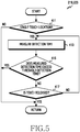
- FIG. 5 is a flowchart illustrating a second example of the procedure of determining the touch event corresponding to the main area and the edge area in FIG. 3 according to an embodiment of the present disclosure.
- a touch event determination procedure when a touch is maintained at a single touch location as illustrated in FIGS. 19A and 19B , 20A and 20B , 21A and 21B , or 22A and 22B will be described below.
- the touch event determination procedure starts by identifying a single touch location by the processor 150 in operation 411.
- the analysis unit 153 may identify the detection time of the touch location. Further, the analysis unit 153 may detect the number of touch locations based on the detection time. Here, the analysis unit 153 may identify the single touch location based on the detection time.
- the processor 150 measures the detection time of the touch in operation 413.
- the determination unit 151 may continue to detect the location of the touch.
- the determination unit 151 may detect the detection time of the touch location, together with the touch location.
- the analysis unit 153 may analyze the touch location.
- the analysis unit 153 may determine whether the touch location changes as the detection time changes. Further, when the touch location does not change, the analysis unit 153 may determine that the touch is maintained at the same touch location.
- the measurement unit 155 may measure the detection time of the touch. Namely, the measurement unit 155 may measure the maintenance time of the touch from the change of the detection time at the same touch location. In this way, the processor 150 may determine a touch event from the detection time of the touch.
- the processor 150 compares the detection time of the touch with a threshold detection time in operation 415. Namely, the processor 150 determines whether the detection time of the touch exceeds the threshold detection time.
- the memory 140 may store the threshold detection time.
- the processor 150 detects the release of the touch in operation 417.
- the processor 150 ends the touch event determination procedure and returns to FIG. 3 . If the release of the touch is not detected in operation 417, the processor 150 returns to operation 413. Then, the processor 150 may repeatedly perform at least some of the operations 413 to 417.
- the processor 150 ends the touch event determination procedure and returns to FIG. 3 .
- the processor 150 may update the touch event. Namely, as the detection time of the touch changes, the processor 150 may change the touch event.
- the touch may be maintained at the initial touch location within the main area 131.
- the touch may be released after the touch is maintained for the threshold detection time or less.
- the touch may be maintained for the threshold detection time or more.
- the touch may be maintained at the initial touch location within the edge area 133.
- the touch may be maintained for the threshold detection time or less.
- the touch may be maintained for the threshold detection time or more.
- FIG. 6 is a flowchart illustrating a third example of the procedure of determining the touch event corresponding to the main area and the edge area in FIG. 3 according to an embodiment of the present disclosure.
- a touch event determination procedure when a touch is maintained at a single touch location as illustrated in FIGS. 23A and 23B , 24A and 25B, 25A and 25B , or 26A and 26B will be described below.
- the touch event determination procedure starts by identifying a single touch location by the processor 150 in operation 511.
- the analysis unit 153 may identify the detection time of the touch location. Further, the analysis unit 153 may detect the number of touch locations based on the detection time. Here, the analysis unit 153 may identify the single touch location based on the detection time.
- the processor 150 detects the release of the touch in operation 513.
- the processor 150 measures the release time of the touch in operation 515.
- the measurement unit 155 may measure the release time of the touch. In this way, the processor 150 may determine a touch event from the number of repeated touches.
- the processor 150 compares the release time of the touch with a threshold release time in operation 517. Namely, the processor 150 determines whether the release time of the touch exceeds the threshold release time.
- the memory 140 may store the threshold release time.
- the processor 150 ends the touch event determination procedure and returns to FIG. 3 .
- the processor 150 detects the release of the touch in operation 519.
- the processor 150 may detect the touch through the input device 120. Further, the processor 150 detects the location of the touch in operation 521.
- the determination unit 151 may detect the location of the touch.
- the determination unit 151 may detect the detection time of the touch location, together with the touch location.
- the processor 150 determines whether the touch location is the same as the initial touch location.
- the analysis unit 153 may analyze the touch location. Further, the analysis unit 153 may determine whether the touch location is the same as the initial touch location.
- the analysis unit 153 may determine that the touch location is the same as the initial touch location.
- the processor 150 returns to operation 513. Then, the processor 150 may repeatedly perform at least some of the operations 513 to 523. In this way, the processor 150 may update the touch event. Namely, as the number of repeated touches changes, the processor 150 may change the touch event.
- the processor 150 ends the procedure of the screen control method.
- the touch may be repeated at the initial touch location within the main area 131.
- the touch may be generated once within the main area 131 as illustrated in FIG. 23A .
- the touch may be repeatedly generated twice at the initial touch location within the main area 131.
- the touch may be repeated at the initial touch location within the edge area 133.
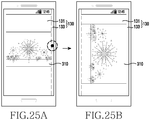
- the touch may be generated once within the edge area 133 as illustrated in FIG. 25A .
- the touch may be repeatedly generated twice at the initial touch location within the edge area 133 as illustrated in FIG. 26A .
- FIG. 7 is a flowchart illustrating a fourth example of the procedure of determining the touch event corresponding to the main area and the edge area in FIG. 3 according to an embodiment of the present disclosure.
- a touch event determination procedure when a touch moves from at least one of a plurality of touch locations as illustrated in FIGS. 27A and 27B , or 28A and 28B , will be described below.
- the touch event determination procedure starts by identifying a plurality of touch locations by the processor 150 in operation 611.
- the analysis unit 153 may identify the detection times of the touch locations. Further, the analysis unit 153 may detect the number of touch locations based on the detection times. Here, the analysis unit 153 may identify the plurality of touch locations based on the detection times.
- the processor 150 detects the movement of the touches in operation 613.
- the determination unit 151 may continue to detect the touch locations.
- the determination unit 151 may detect the detection times of the touch locations, together with the touch locations.
- the analysis unit 153 may analyze the touch locations.
- the analysis unit 153 may determine whether at least one of the touch locations changes as the detection times change. Further, when at least one of the touch locations changes, the analysis unit 153 may determine the movement of the touch.
- the processor 150 tracks the moving paths of the touches.
- the measurement unit 155 may track the moving paths of the touches.
- the measurement unit 155 may track the change of the touch locations as the detection times change.
- the processor 150 may measure the moving directions and the moving distances of the touches in operation 617.
- the measurement unit 155 may measure the moving directions and the moving distances of the touches along the moving paths of the touches. In this way, the processor 150 may determine a touch event from the moving paths, the moving directions, and the moving distances of the touches.
- the processor 150 detects the release of the touches in operation 619.
- the processor 150 ends the touch event determination procedure and returns to FIG. 3 .
- the processor 150 when the release of the touches is not detected in operation 619, the processor 150 returns to operation 613. Then, the processor 150 may repeatedly perform at least some of the operations 613 to 619. In this way, the processor 150 may update the touch event. Namely, the processor 150 may change the touch event as at least one of the moving paths, the moving directions, and the moving distances of the touches changes.
- the touches may move from the main area 131.
- the touches may move within the main area 131.
- the touch locations may move away from each other within the main area 131.
- the touch locations may move close to each other within the main area 131.
- the touches may move from the edge area 133.
- the touches may move within the edge area 133.
- the touch locations may move away from each other within the edge area 133.
- the touch locations may move close to each other within the edge area 133.
- FIG. 8 is a flowchart illustrating a fifth example of the procedure of determining the touch event corresponding to the main area and the edge area in FIG. 3 according to an embodiment of the present disclosure.
- the touch event determination procedure starts by identifying a plurality of touch locations by the processor 150 in operation 711.
- the analysis unit 153 may identify the detection times of the touch locations. Further, the analysis unit 153 may detect the number of touch locations based on the detection times. Here, the analysis unit 153 may identify the plurality of touch locations based on the detection times.
- the processor 150 measures the detection times of the touches in operation 713.
- the determination unit 151 may continue to detect the touch locations.
- the determination unit 151 may detect the detection times of the touch locations, together with the touch locations.
- the analysis unit 153 may analyze the touch locations.
- the analysis unit 153 may determine whether at least one of the touch locations changes as the detection times change. Further, when the touch locations do not change, the analysis unit 153 may determine that the touches are maintained at the same touch locations.
- the measurement unit 155 may measure the detection times of the touches. Namely, the measurement unit 155 may measure the maintenance times of the touches from the change of the detection times at the same touch locations.
- the processor 150 compares the detection times of the touches with a threshold detection time in operation 715. Namely, the processor 150 determines whether the detection times of the touches exceed the threshold detection time.
- the memory 140 may store the threshold detection time.
- the processor 150 detects the release of the touches in operation 723. Then, the processor 150 ends the procedure of the screen control method. If the release of the touches is not detected in operation 723, the processor 150 returns to operation 713. Then, the processor 150 may repeatedly perform at least some of the operations 713 to 723.
- the processor 150 analyzes the arrangement structure of the touch locations in operation 717. Namely, the processor 150 analyzes the arrangement structure of the touch locations within the edge area 133. Thereafter, the processor 150 compares the arrangement structure of the touch locations with the set arrangement structure in operation 719. Namely, the processor 150 determines whether the arrangement structure of the touch locations is the same as the set arrangement structure.
- the memory 140 may store the set arrangement structure.
- the set arrangement structure may include a right-hand grip structure and a left-hand grip structure.
- the right-hand grip structure may refer to a case in which the user of the electronic device 100 grips the electronic device 100 with his/her right hand
- the left-hand grip structure may refer to a case in which the user of the electronic device 100 grips the electronic device 100 with his/her left hand.
- the processor 150 determines the direction of the display screen 310 in operation 721. Namely, the processor 150 may determine a touch event according to the arrangement structure of the touch locations. For example, when the arrangement structure of the touch locations is the same as the right-hand grip structure, the processor 150 may determine a touch event in response to the right-hand grip structure. Alternatively, when the arrangement structure of the touch locations is the same as the left-hand grip structure, the processor 150 may determine a touch event in response to the left-hand grip structure. Thereafter, the processor 150 ends the touch event determination procedure and returns to FIG. 3 .
- the processor 150 ends the procedure of the screen control method.
- the touches may be maintained at the initial touch locations within the edge area 133.
- at least three initial touch locations may be arranged in the edge area 133.
- one of the initial touch locations may be arranged in the edge area 133 on the right side of the main area 131, and the rest of the initial touch locations may be arranged to be separated from each other in the edge area 133 on the left side of the main area 131.
- the processor 150 may determine that the arrangement structure of the initial touch locations is the same as the right-hand grip structure.
- FIG. 29A one of the initial touch locations may be arranged in the edge area 133 on the right side of the main area 131, and the rest of the initial touch locations may be arranged to be separated from each other in the edge area 133 on the left side of the main area 131.
- the processor 150 may determine that the arrangement structure of the initial touch locations is the same as the right-hand grip structure.
- one of the initial touch locations may be arranged in the edge area 133 on the left side of the main area 131, and the rest of the initial touch locations may be arranged to be separated from each other in the edge area 133 on the right side of the main area 131.
- the processor 150 may determine that the arrangement structure of the initial touch locations is the same as the left-hand grip structure.
- the processor 150 controls the display screen 310 in operation 225.
- the processor 150 controls the display screen 310 in response to the touch event.
- the processor 150 may control the display screen according to at least one of the touch location and the touch motion.
- the processor 150 may control the display screen 310 according to the movement of the touch as illustrated in FIGS. 10A and 10B , 11A and 11B , or 12A and 12B .
- the processor 150 may scroll up the list of received messages in units of items on the display screen 310.
- the processor 150 may scroll down the list of received messages on the display screen 310.
- the processor 150 may select one of received messages and may display detailed contents of the selected message on the display screen 310.
- the processor 150 may select one of received messages and may make a call to the phone number for the selected message.
- the processor 150 may display the outgoing call information on the display screen 310.
- the processor 150 may control the display screen 310 according to the movement of the touch as illustrated in FIGS. 13A and 13B , 14A and 14B , 15A and 15B , 16A and 16B , 17A and 17B , or 18A and 18B .
- the processor 150 may scroll up the list of received messages on the display screen 310 to display the lower end portion of the received messages.
- the processor 150 may scroll down the list of received messages on the display screen 310 to display the upper end portion of the received messages.
- the processor 150 may control the volume to correspond to the display screen 310.
- the processor 150 may execute a set function as illustrated in FIG. 14B .
- the processor 150 may execute, for example, a camera function.
- the processor 150 may execute the preceding function as illustrated in FIG. 15B .
- the processor 150 may execute an image display function.
- the processor 150 may execute the next function as illustrated in FIG. 16B .
- the processor 150 may execute an outgoing call function.
- the processor 150 may display an auxiliary panel in response to a function set according to the movement of a touch.
- the processor 150 may display weather information on the auxiliary panel.
- the processor 150 may display an auxiliary panel in response to a function set according to the movement of a touch.
- the processor 150 may display dictionary information on the auxiliary panel.
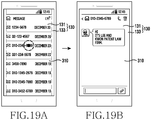
- the processor 150 may control the display screen 310 according to the detection time of the touch as illustrated in FIGS. 19A and 19B , or 20A and 20B .
- the processor 150 may select one of received messages and may display detailed contents of the selected message on the display screen 310.
- the processor 150 may select one of received messages and may display, on the display screen 310, an auxiliary window for processing the phone number for the selected received message.
- the processor 150 may control the display screen 310 according to the detection time of the touch as illustrated in FIGS. 21A and 21B , or 22A and 22B .
- the processor 150 may select one of received messages and may display, on the display screen 310, an auxiliary window for storing the phone number for the selected message.
- the processor 150 may execute a set function as illustrated in FIG. 22B .
- the processor 150 may execute a search function.
- the processor 150 may also execute a refresh function.
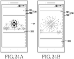
- the processor 150 may control the display screen 310 according to the number of repeated touches as illustrated in FIGS. 23A and 23B , or 24A and 24B .
- the processor 150 may display the list of displayable images on the display screen 310.
- the processor 150 may display a zoomed-in image on the display screen 310.
- the processor 150 may control the display screen 310 according to the number of repeated touches as illustrated in FIGS. 25A and 25B , or 26A and 26B .
- the processor 150 may display a rotated and zoomed-in image on the display screen 310.
- the processor 150 may edit an image on the display screen 310.
- the processor 150 may execute a set function.
- the processor 150 may execute a search function.
- the processor 150 may execute a refresh function.
- the processor 150 may control the display screen 310 according to the movement of the touches as illustrated in FIGS. 27A and 27B .
- the processor 150 may display a zoomed-in image on the display screen 310.
- the processor 150 may display a zoomed-out image on the display screen 310.
- the processor 150 may control the display screen 310 according to the movement of the touches as illustrated in FIGS. 28A and 28B .
- the processor 150 may adjust the brightness of an image on the display screen 310.
- the processor 150 may control the display screen 310 according to the arrangement structure of the touch locations as illustrated in FIGS. 29A and 29B , or 30A and 30B .
- the processor 150 may display a numeric keypad on the right side of the display screen 310.
- the processor 150 may display a numeric keypad on the left side of the display screen 310.
- the processor 150 determines whether to complete the control of the display screen 310.
- the processor 150 ends the procedure of the screen control method.
- the processor 150 may end the procedure of the screen control method when a user input for deactivating the display 130 or a user input for turning off the electronic device 100 is detected.
- the processor 150 may deactivate both the main area 131 and the edge area 133.
- the processor 150 may deactivate the main area 131 and may continually activate the edge area 133.
- the processor 150 may deactivate the input device 120 to correspond to the main area 131 and the edge area 133.
- the processor 150 may deactivate the input device 120 to correspond to the main area 131 and may continually activate the input device 120 to correspond to the edge area 133.
- the processor 150 returns to operation 211. Thereafter, the processor 150 may repeatedly perform at least some of the operations 211 to 227.
- the processor 150 may control the display screen 310 while the touch is being released.
- the processor 150 may control the display screen 310 according to one of the touch location and the touch motion.
- the processor 150 may control the display screen 310 according to at least one of the touch location and the touch motion.
- the processor 150 may control the display screen 310 according to the movement of the touch or the detection time of the touch.
- the display 130 of the electronic device 100 includes not only the main area 131 but also the edge area 133. This can create a touch motion that is generated from not only the main area 131 but also from the edge area 133 in the electronic device 100. Accordingly, the electronic device 100 can provide various interactions for various touch motions. Namely, the electronic device 100 can control the display screen in response to various touch motions. Therefore, the electronic device 100 can enhance use efficiency user convenience thereof.
Landscapes
- Engineering & Computer Science (AREA)
- Theoretical Computer Science (AREA)
- General Engineering & Computer Science (AREA)
- Human Computer Interaction (AREA)
- Physics & Mathematics (AREA)
- General Physics & Mathematics (AREA)
- Health & Medical Sciences (AREA)
- Audiology, Speech & Language Pathology (AREA)
- General Health & Medical Sciences (AREA)
- User Interface Of Digital Computer (AREA)
- Telephone Function (AREA)
Description
- The present disclosure relates to an electronic device and an operating method thereof. More specifically, the present disclosure relates to an electronic device that has a display that includes a main area and an edge area extending from the main area, and a method of operating the same.
- In general, electronic devices have various functions added thereto and perform these functions in combination. For example, electronic devices may perform mobile communication functions, data communication functions, data output functions, data storage functions, image photographing functions, audio recording functions, etc. Such electronic devices include a display and an input device. In this case, the display and the input device may be coupled to each other so as to be implemented as a touchscreen. Further, the electronic devices may output display screens through the touchscreen. In addition, the electronic devices may control the display screens by detecting touches on the touchscreen.
- However, the electronic devices do not provide various interactions for various touch motions. Due to this, the electronic devices have difficulty in controlling the display screens in response to various touch motions. Accordingly, the use efficiency of the electronic devices and user convenience may be degraded.
US 2012/304133 A1 discloses a device with a flat touch screen. A touch dragged from an edge portion to the main area of the screen is used to invoke a new window or screen. - The above information is presented as background information only to assist with an understanding of the present disclosure. No determination has been made, and no assertion is made, as to whether any of the above might be applicable as prior art with regard to the present disclosure. The invention is defined by the independent claims. Further aspects of the invention are outlined in the dependent claims. When the term embodiment is used for describing unclaimed combinations of features, the term has to be understood as referring to examples useful for understanding the present invention.
- Aspects of the present disclosure are to address at least the above-mentioned problems and/or disadvantages and to provide at least the advantages described below. Accordingly, an aspect of the present disclosure is to provide an electronic device that has a display that includes a main area and an edge area extending from the main area, and a method of operating the same.
- In accordance with an aspect of the present disclosure, a method of operating an electronic device is provided. The method includes outputting a display screen on a display that has a main area and an edge area extending from an edge of the main area, when detecting a touch, determining a location of the touch in one of the main area and the edge area, and controlling the display screen according to the location of the touch.
- In accordance with another aspect of the present disclosure, an electronic device is provided. The electronic device includes a display including a main area and an edge area extending from an edge of the main area, and configured to output a display screen in at least one of the main area and the edge area, an input device configured to detect a touch, a determination unit configured to determine a location of the touch in one of the main area and the edge area when the touch is detected, and a processor configured to control the display screen according to the location of the touch.
- In the screen control device and method of the present disclosure, the display includes not only the main area but also the edge area. This can create a touch motion that is generated from not only the main area but also the edge area in the screen control device. Accordingly, the screen control device can provide various interactions for various touch motions. Namely, the screen control device can control the display screen in response to various touch motions. Therefore, the screen control device can enhance use efficiency and user convenience of the electronic device.
- Other aspects, advantages, and salient features of the disclosure will become apparent to those skilled in the art from the following detailed description, which, taken in conjunction with the annexed drawings, discloses various embodiments of the present disclosure.
- The above and other aspects, features, and advantages of certain embodiments of the present disclosure will be more apparent from the following description taken in conjunction with the accompanying drawings, in which:
-
FIG. 1 is a block diagram of an electronic device according to an embodiment of the present disclosure; -
FIG. 2 illustrates implemented examples of the electronic device according to an embodiment of the present disclosure; -
FIG. 3 is a flowchart illustrating a procedure of a screen control method according to an embodiment of the present disclosure; -
FIG. 4 is a flowchart illustrating a first example of the procedure of determining the touch event corresponding to the main area and the edge area inFIG. 3 according to an embodiment of the present disclosure; -
FIG. 5 is a flowchart illustrating a second example of the procedure of determining the touch event corresponding to the main area and the edge area inFIG. 3 according to an embodiment of the present disclosure; -
FIG. 6 is a flowchart illustrating a third example of the procedure of determining the touch event corresponding to the main area and the edge area inFIG. 3 according to an embodiment of the present disclosure; -
FIG. 7 is a flowchart illustrating a fourth example of the procedure of determining the touch event corresponding to the main area and the edge area inFIG. 3 according to an embodiment of the present disclosure; -
FIG. 8 is a flowchart illustrating a fifth example of the procedure of determining the touch event corresponding to the main area and the edge area inFIG. 3 according to an embodiment of the present disclosure; and -
FIGS. 9A to 30B illustrate examples for explaining the screen control method according to various embodiments of the present disclosure. - Throughout the drawings, it should be noted that like reference numbers are used to depict the same or similar elements, features, and structures.
- The following description with reference to the accompanying drawings is provided to assist in a comprehensive understanding of various embodiments of the present disclosure as defined by the claims and their equivalents. It includes various specific details to assist in that understanding but these are to be regarded as merely exemplary. Accordingly, those of ordinary skill in the art will recognize that various changes and modifications of the various embodiments described herein can be made without departing from the scope of the present disclosure. In addition, descriptions of well-known functions and constructions may be omitted for clarity and conciseness.
- The terms and words used in the following description and claims are not limited to the bibliographical meanings, but, are merely used by the inventor to enable a clear and consistent understanding of the present disclosure. Accordingly, it should be apparent to those skilled in the art that the following description of various embodiments of the present disclosure is provided for illustration purpose only and not for the purpose of limiting the present disclosure as defined by the appended claims.
- It is to be understood that the singular forms "a," "an," and "the" include plural referents unless the context clearly dictates otherwise. Thus, for example, reference to "a component surface" includes reference to one or more of such surfaces.
-
FIG. 1 is a block diagram of an electronic device according to an embodiment of the present disclosure.FIG. 2 illustrates implemented examples of the electronic device according to an embodiment of the present disclosure. Here, view (a) ofFIG. 2 is a plan view of the electronic device, and views (b) to (e) are cross-sectional views taken along line A-A' of view (a) ofFIG. 2 . - Referring to
FIG. 1 , theelectronic device 100 of this embodiment of the present disclosure includes acommunication unit 110, aninput device 120, adisplay 130, amemory 140, aprocessor 150, and anaudio processor 160. - The
communication unit 110 performs communication in theelectronic device 100. In this case, thecommunication unit 110 may communicate with an external device (not illustrated) in various communication schemes. Here, thecommunication unit 110 may perform at least one of wireless communication and wired communication. To this end, thecommunication unit 110 may connect to at least one of a mobile communication network and a data communication network. Alternatively, thecommunication unit 110 may perform short range communication. For example, the external device may include an electronic device, a base station, a server, and a satellite. The communication schemes may include long term evolution (LTE), wideband code division multiple access (WCDMA), global system for mobile communications (GSM), Wi-Fi, Bluetooth, and near field communications (NFC). - The
input device 120 generates input data in theelectronic device 100. In this case, theinput device 120 may generate the input data in response to a user input of theelectronic device 100. Further, theinput device 120 may include at least one input means. Theinput device 120 may include a key pad, a dome switch, a physical button, a touch panel, a jog & shuttle, and a sensor. - The
display 130 outputs a display screen. Here, the display screen may include at least one of an image and a text. Thedisplay 130 may include a liquid crystal display (LCD), a light emitting diode (LED) display, an organic LED (OLED) display, a micro electro mechanical system (MEMS) display, or an electronic paper display. Here, thedisplay 130 may include a plurality of light emitting diodes. Further, thedisplay 130 may be coupled with theinput device 120 so as to be implemented as a touchscreen. - As illustrated in view (a) of
FIG. 2 , thedisplay 130 may include amain area 131 and anedge area 133. In this case, themain area 131 and theedge area 133 may output a display screen. Namely, the display screen may be output in parts by themain area 131 and theedge area 133. Alternatively, themain area 131 may output the whole display screen. In this case, theedge area 133 may output color light. Themain area 131 is disposed on the front side of theelectronic device 100. Theedge area 133 extends from an edge of themain area 131. Namely, theedge area 133 may extend from at least one of the upper, lower, left and right sides of themain area 131. Here, theedge area 133 may be integrally formed with themain area 131. - As illustrated in view (b) or (c) of
FIG. 2 , themain area 131 and theedge area 133 may be formed of a flat surface. Here, as illustrated in view (b) ofFIG. 2 , themain area 131 and theedge area 133 may be disposed on the same plane. In this way, theedge area 133 may be disposed on the front side of theelectronic device 100. Alternatively, as illustrated in view (c) ofFIG. 2 , theedge area 133 may be inclined with respect to themain area 131. In other words, theedge area 133 may extend from themain area 131 toward the rear side of theelectronic device 100. In this way, theedge area 133 may be disposed on the lateral side of theelectronic device 100. - Meanwhile, as illustrated in view (d) or (e) of
FIG. 2 , at least one of themain area 131 and theedge area 133 may be formed of a curved surface. Here, as illustrated in view (d) ofFIG. 2 , themain area 131 may be formed of a flat plane, and theedge area 133 may be formed of a curved surface. Alternatively, although not illustrated, themain area 131 may be formed of a curved surface, and theedge area 133 may be formed of a flat plane. In another case, as illustrated in view (e) ofFIG. 2 , themain area 131 and theedge area 133 may be formed of a single curved surface. Alternatively, although not illustrated, themain area 131 and theedge area 133 may be formed of different curved surfaces. In this way, theedge area 133 may be inclined with respect to themain area 131. In other words, theedge area 133 may extend from themain area 131 toward the rear side of theelectronic device 100. Theedge area 133 may be disposed on the lateral side of theelectronic device 100. - To this end, the
display 130 may be manufactured to have flexibility and may then be bent. In this case, thedisplay 130 may be partially bent. Here, thedisplay 130 is bent or curved so that theedge area 133 may be inclined with respect to themain area 131. Specifically, thedisplay 130 may be bent or curved with respect to the border between themain area 131 and theedge area 133. Further, as at least one of themain area 131 and theedge area 133 is curved, thedisplay 130 may be formed of a curved surface. Specifically, one of themain area 131 and theedge area 133 may be curved, and themain area 131 and theedge area 133 may also be curved to have different curvatures. Alternatively, thedisplay 130 may be bent on the whole. Here, themain area 131 and theedge area 133 may be integrally curved. In other words, themain area 131 and theedge area 133 may be curved to have the same curvature. - The
memory 140 stores operating programs of theelectronic device 100. In this case, thememory 140 may store a program for controlling a display screen according to a user input. Further, thememory 140 stores data generated while the programs are executed. In addition, thememory 140 stores functions for controlling a display screen. In this case, thememory 140 may match touch events and the functions and then store them. - The
processor 150 controls an overall operation in theelectronic device 100. In this case, theprocessor 150 performs various functions. Further, theprocessor 150 controls thedisplay 130 to output a display screen. In addition, theprocessor 150 controls a display screen. Here, theprocessor 150 may control themain area 131 and theedge area 133 separately, or by making an association therebetween. Besides, theprocessor 150 may detect a user input through theinput device 120 to correspond to themain area 131 and theedge area 133. Namely, theprocessor 150 may detect a touch through theinput device 120. In addition, theprocessor 150 may determine a touch event. Here, theprocessor 150 may determine the touch event according to at least one of a touch location and a touch motion. In this way, theprocessor 150 may control a display screen in response to the touch event. Theprocessor 150 may include a determination unit 151, ananalysis unit 153, and ameasurement unit 155. Accordingly, theprocessor 150 may perform any of the operations described herein as being performed by the determination unit 151, theanalysis unit 153, and themeasurement unit 155. Further, one or more of the determination unit 151, theanalysis unit 153, and themeasurement unit 155 may be included in another processor or as at least one component separate from theprocessor 150. - The determination unit 151 may detect the location of a touch. Here, the determination unit 151 may detect the detection time of the touch location, together with the touch location. The determination unit 151 may detect the touch location as coordinates. For example, the determination unit 151 may detect a plurality of coordinates in the area of the touch and may select one of the coordinates to determine the same as the touch location. To this end, if there is a space in the area of the touch, the determination unit 151 may divide the area of the touch. Further, the determination unit 151 may detect the touch location as positive (+) coordinates in the
main area 131 and as negative (-) coordinates in theedge area 133. In this way, theprocessor 150 may control a display screen in response to the touch location. In this case, the determination unit 151 may determine an initial touch location on thedisplay 130. Here, the initial touch location may represent the location where the touch was first generated. Namely, the determination unit 151 may determine the initial touch location in one of themain area 131 and theedge area 133. In this way, theprocessor 150 may control a display screen according to the initial touch location. - The
analysis unit 153 may analyze a touch location. In this case, theanalysis unit 153 may identify the detection time of the touch location. Further, theanalysis unit 153 may detect the number of touch locations based on the detection time. Here, theanalysis unit 153 may identify a single touch location and may also identify a plurality of touch locations based on the detection time. Namely, a plurality of simultaneously generated touch locations may be detected by theanalysis unit 153. In this way, theprocessor 150 may control a display screen according to the number of touch locations. Besides, theanalysis unit 153 may analyze the arrangement structure of the plurality of touch locations. In this way, theprocessor 150 may control a display screen according to the arrangement structure of the plurality of touch locations. - The
measurement unit 155 may track a touch motion. In this case, in response to the movement of the touch, themeasurement unit 155 may measure the moving direction, the moving path, and the moving distance of the touch. In this way, theprocessor 150 may control a display screen according to the movement of the touch. Further, themeasurement unit 155 may measure the detection time of the touch. Here, the detection time of the touch may represent the maintenance time of the touch at the same location. In this way, theprocessor 150 may control a display screen according to the detection time of the touch. In addition, themeasurement unit 155 may measure the number of repeated touches. Here, the number of repeated touches may represent the number of times that a touch is detected at the same location. In this way, theprocessor 150 may control a display screen according to the number of repeated touches. - The
audio processor 160 processes an audio signal. In this case, theaudio processor 160 includes a speaker (SPK) 161 and a microphone (MIC) 163. Namely, theaudio processor 160 may reproduce an audio signal output from theprocessor 150 through theSPK 161. Further, theaudio processor 160 may forward, to theprocessor 150, an audio signal generated by theMIC 163. -
FIG. 3 is a flowchart illustrating a procedure of a screen control method according to an embodiment of the present disclosure.FIGS. 9A to 30B illustrate examples for explaining the screen control method according to various embodiments of the present disclosure. - Referring to
FIG. 3 , the procedure of the screen control method, according to this embodiment of the present disclosure, starts by outputting adisplay screen 310 by theprocessor 150 inoperation 211. In this case, theprocessor 150 outputs thedisplay screen 310 through thedisplay 130 to correspond to a current function. Here, theprocessor 150 may activate both themain area 131 and theedge area 133. Further, theprocessor 150 may output split screens, into which thedisplay screen 310 is split, in themain area 131 and theedge area 133. Alternatively, theprocessor 150 may output thedisplay screen 310 in themain area 131. Further, theprocessor 150 may activate theinput device 120 to correspond to themain area 131 and theedge area 133. - For example, the
processor 150 may output thedisplay screen 310 as illustrated inFIGS. 9A to 9C . In this case, theprocessor 150 may display an image on thedisplay screen 310 as illustrated inFIG. 9A in response to an image display function. Alternatively, theprocessor 150 may display a list of received messages on thedisplay screen 310 as illustrated inFIG. 9B in response to a received-message display function. Here, if the received-message display function is executed while the image display function is being performed, theprocessor 150 may display the list of received messages on thedisplay screen 310 as illustrated inFIG. 9B . In another case, theprocessor 150 may display a numeric keypad for call origination on thedisplay screen 310 as illustrated inFIG. 9C in response to a call origination function. Here, if the call origination function is executed while the received-message display function is being performed, theprocessor 150 may display the numeric keypad for call origination on thedisplay screen 310 as illustrated inFIG. 9C . - Next, when a touch is generated, the
processor 150 detects the touch inoperation 213. In this case, theprocessor 150 may detect the touch through theinput device 120. Further, theprocessor 150 detects the location of the touch inoperation 215. Namely, theprocessor 150 detects an initial touch location. In this case, the determination unit 151 may detect the location of the touch. Here, the determination unit 151 may detect the detection time of the touch location, together with the touch location. - In this case, the determination unit 151 may detect the touch location as coordinates. For example, the determination unit 151 may detect a plurality of coordinates in the area of the touch and may select one of the coordinates to determine the same as the touch location. Further, the determination unit 151 may detect the touch location as positive (+) coordinates in the
main area 131 and as negative (-) coordinates in theedge area 133. - Here, the
processor 150 may detect a single touch location and may also simultaneously detect a plurality of touch locations. Namely, if there is a space in the area of the touch, the determination unit 151 may divide the touch area into a plurality of partial areas based on the space. The determination unit 151 may detect touch locations in the respective partial areas. In other words, the determination unit 151 may detect each of the touch locations as coordinates. - Then, in
operation 217, theprocessor 150 determines whether the touch location is within themain area 131. Namely, theprocessor 150 determines whether the initial touch location is within themain area 131. When the determination result inoperation 217 shows that the touch location is within themain area 131, theprocessor 150 determines a touch event inoperation 219. Namely, theprocessor 150 determines the touch event to correspond to themain area 131. - In this case, the
processor 150 may determine the touch event according to at least one of the touch location and the touch motion. For example, theprocessor 150 may determine a touch event from the movement of a touch as illustrated inFIGS. 10A and 10B ,11A and11B , or12A and 12B . Alternatively, theprocessor 150 may determine a touch event from the detection time of a touch as illustrated inFIGS. 19A and 19B , or20A and 20B . In another case, theprocessor 150 may determine a touch event from the number of repeated touches as illustrated inFIGS. 23A and 23B , or24A and23B . In yet another case, theprocessor 150 may determine a touch event from the number of touch locations as illustrated inFIGS. 27A and 27B . To this end, theanalysis unit 153 may analyze the touch location. Further, themeasurement unit 155 may track the touch motion. Here, the procedure of determining the touch event by theprocessor 150 to correspond to themain area 131 will be described below in more detail with reference toFIGS. 4 to 7 . - Meanwhile, when the determination result in
operation 217 shows that the touch location is not within themain area 131, theprocessor 150 determines whether the touch location is within theedge area 133 inoperation 221. Namely, theprocessor 150 determines whether the initial touch location is within theedge area 133. When the determination result inoperation 221 shows that the touch location is within theedge area 133, theprocessor 150 determines a touch event inoperation 223. Namely, theprocessor 150 determines the touch event to correspond to theedge area 133. - In this case, the
processor 150 may determine the touch event according to at least one of the touch location and the touch motion. For example, theprocessor 150 may determine a touch event from the movement of a touch as illustrated inFIGS. 13A and 13B ,14A and14B ,15A and15B ,16A and16B ,17A and17B , or18A and 18B . Alternatively, theprocessor 150 may determine a touch event from the detection time of a touch as illustrated inFIGS. 21A and 21B , or22A and 22B . In another case, theprocessor 150 may determine a touch event from the number of repeated touches as illustrated inFIGS. 25A and 25B , or26A and 26B . In yet another case, theprocessor 150 may determine a touch event from the number of touch locations as illustrated inFIGS. 28A and 28B . In yet another case, theprocessor 150 may determine a touch event from the arrangement structure of touch locations as illustrated inFIGS. 29A and 29B , or30A and 30B . To this end, theanalysis unit 153 may analyze the touch location. Further, themeasurement unit 155 may track the touch motion. Here, the procedure of determining the touch event by theprocessor 150 to correspond to theedge area 133 will be described below in more detail with reference toFIGS. 4 to 8 . - Meanwhile, when the determination result in
operation 221 shows that the touch location is not within theedge area 133, theprocessor 150 returns tooperation 211. Thereafter, theprocessor 150 may repeatedly perform at least some of theoperations 211 to 223. -
FIG. 4 is a flowchart illustrating a first example of the procedure of determining the touch event corresponding to the main area and the edge area inFIG. 3 according to an embodiment of the present disclosure. A touch event determination procedure when a touch moves from a single touch location as illustrated inFIGS. 10A and 10B ,11A and11B ,12A and12B ,13A and13B ,14A and14B ,15A and15B ,16A and16B ,17A and17B , or18A and 18B will be described below. - Referring to
FIG. 4 , the touch event determination procedure, according to this embodiment of the present disclosure, starts by identifying a single touch location by theprocessor 150 inoperation 311. In this case, theanalysis unit 153 may identify the detection time of the touch location. Further, theanalysis unit 153 may detect the number of touch locations based on the detection time. Here, theanalysis unit 153 may identify the single touch location based on the detection time. - Next, when the touch moves, the
processor 150 detects the movement of the touch inoperation 313. In this case, the determination unit 151 may continue to detect the location of the touch. Here, the determination unit 151 may detect the detection time of the touch location, together with the touch location. Theanalysis unit 153 may analyze the touch location. Here, theanalysis unit 153 may determine whether the touch location changes as the detection time changes. Further, when the touch location changes, theanalysis unit 153 may determine the movement of the touch. - Next, in
operation 315, theprocessor 150 tracks the moving path of the touch. In this case, themeasurement unit 155 may track the moving path of the touch. Here, themeasurement unit 155 may track the change of the touch location as the detection time changes. Theprocessor 150 may measure the moving direction and the moving distance of the touch inoperation 317. In this case, themeasurement unit 155 may measure the moving direction and the moving distance of the touch along the moving path of the touch. In this way, theprocessor 150 may determine a touch event from the moving path, the moving direction, and the moving distance of the touch. - Next, when the touch is released, the
processor 150 detects the release of the touch inoperation 319. Further, theprocessor 150 ends the touch event determination procedure and returns toFIG. 3 . - Meanwhile, when the release of the touch is not detected in
operation 319, theprocessor 150 returns tooperation 313. Then, theprocessor 150 may repeatedly perform at least some of theoperations 313 to 319. In this way, theprocessor 150 may update the touch event. Namely, theprocessor 150 may change the touch event as at least one of the moving path, the moving direction, and the moving distance of the touch changes. - In cases where the initial touch location is within the
main area 131, the touch may move from themain area 131. Here, the touch may move within themain area 131. For example, the touch may move upward within themain area 131 as illustrated inFIG. 10A . Alternatively, although not illustrated, the touch may move downward within themain area 131. In another case, the touch may move leftward within themain area 131 as illustrated inFIG. 11A . In yet another case, although not illustrated, the touch may move rightward within themain area 131. Meanwhile, the touch may move from themain area 131 to theedge area 133. For example, as illustrated inFIG. 12A , the touch may move leftward from themain area 131 to reach theedge area 133. In yet another case, although not illustrated, the touch may move rightward from themain area 131 to reach theedge area 133. - Meanwhile, in cases where the initial touch location is within the
edge area 133, the touch may move from theedge area 133. Here, the touch may move within theedge area 133. For example, the touch may move upward within theedge area 133 as illustrated inFIG. 13A . Alternatively, although not illustrated, the touch may move downward within theedge area 133. In another case, the touch may move upward and downward within theedge area 133 as illustrated inFIG. 14A . Meanwhile, the touch may move from theedge area 133 to themain area 131. For example, as illustrated inFIG. 15A or17A , the touch may move rightward from theedge area 133 to reach themain area 131. In yet another case, as illustrated inFIG. 16A or18A , the touch may move leftward from theedge area 133 to reach themain area 131. -
FIG. 5 is a flowchart illustrating a second example of the procedure of determining the touch event corresponding to the main area and the edge area inFIG. 3 according to an embodiment of the present disclosure. A touch event determination procedure when a touch is maintained at a single touch location as illustrated inFIGS. 19A and 19B ,20A and20B ,21A and21B , or22A and 22B will be described below. - Referring to
FIG. 5 , the touch event determination procedure, according to this embodiment of the present disclosure, starts by identifying a single touch location by theprocessor 150 inoperation 411. In this case, theanalysis unit 153 may identify the detection time of the touch location. Further, theanalysis unit 153 may detect the number of touch locations based on the detection time. Here, theanalysis unit 153 may identify the single touch location based on the detection time. - Next, the
processor 150 measures the detection time of the touch inoperation 413. In this case, the determination unit 151 may continue to detect the location of the touch. Here, the determination unit 151 may detect the detection time of the touch location, together with the touch location. Theanalysis unit 153 may analyze the touch location. Here, theanalysis unit 153 may determine whether the touch location changes as the detection time changes. Further, when the touch location does not change, theanalysis unit 153 may determine that the touch is maintained at the same touch location. Further, themeasurement unit 155 may measure the detection time of the touch. Namely, themeasurement unit 155 may measure the maintenance time of the touch from the change of the detection time at the same touch location. In this way, theprocessor 150 may determine a touch event from the detection time of the touch. - Next, the
processor 150 compares the detection time of the touch with a threshold detection time inoperation 415. Namely, theprocessor 150 determines whether the detection time of the touch exceeds the threshold detection time. Here, thememory 140 may store the threshold detection time. - Next, when the determination result in
operation 415 shows that the detection time of the touch does not exceed the threshold detection time, and the touch is released, theprocessor 150 detects the release of the touch inoperation 417. Theprocessor 150 ends the touch event determination procedure and returns toFIG. 3 . If the release of the touch is not detected inoperation 417, theprocessor 150 returns tooperation 413. Then, theprocessor 150 may repeatedly perform at least some of theoperations 413 to 417. - Meanwhile, when the determination result in
operation 415 shows that the detection time of the touch exceeds the threshold detection time, theprocessor 150 ends the touch event determination procedure and returns toFIG. 3 . In this case, theprocessor 150 may update the touch event. Namely, as the detection time of the touch changes, theprocessor 150 may change the touch event. - In cases where the initial touch location is within the
main area 131, the touch may be maintained at the initial touch location within themain area 131. For example, as illustrated inFIG. 19A , the touch may be released after the touch is maintained for the threshold detection time or less. Alternatively, as illustrated inFIG. 20A , the touch may be maintained for the threshold detection time or more. - Meanwhile, in cases where the initial touch location is within the
edge area 133, the touch may be maintained at the initial touch location within theedge area 133. For example, as illustrated inFIG. 21A , the touch may be maintained for the threshold detection time or less. Alternatively, as illustrated inFIG. 22A , the touch may be maintained for the threshold detection time or more. -
FIG. 6 is a flowchart illustrating a third example of the procedure of determining the touch event corresponding to the main area and the edge area inFIG. 3 according to an embodiment of the present disclosure. A touch event determination procedure when a touch is maintained at a single touch location as illustrated inFIGS. 23A and 23B ,24A and25B, 25A and 25B , or26A and 26B will be described below. - Referring to
FIG. 6 , the touch event determination procedure, according to this embodiment of the present disclosure, starts by identifying a single touch location by theprocessor 150 inoperation 511. In this case, theanalysis unit 153 may identify the detection time of the touch location. Further, theanalysis unit 153 may detect the number of touch locations based on the detection time. Here, theanalysis unit 153 may identify the single touch location based on the detection time. - Next, when the touch is released, the
processor 150 detects the release of the touch inoperation 513. Theprocessor 150 measures the release time of the touch inoperation 515. In this case, themeasurement unit 155 may measure the release time of the touch. In this way, theprocessor 150 may determine a touch event from the number of repeated touches. - Next, the
processor 150 compares the release time of the touch with a threshold release time inoperation 517. Namely, theprocessor 150 determines whether the release time of the touch exceeds the threshold release time. Here, thememory 140 may store the threshold release time. - Next, when the determination result in
operation 517 shows that the release time of the touch exceeds the threshold release time, theprocessor 150 ends the touch event determination procedure and returns toFIG. 3 . - Meanwhile, when the determination result in
operation 517 shows that the release time of the touch does not exceed the threshold release time, and the touch is released, theprocessor 150 detects the release of the touch inoperation 519. In this case, theprocessor 150 may detect the touch through theinput device 120. Further, theprocessor 150 detects the location of the touch inoperation 521. In this case, the determination unit 151 may detect the location of the touch. Here, the determination unit 151 may detect the detection time of the touch location, together with the touch location. Thereafter, inoperation 523, theprocessor 150 determines whether the touch location is the same as the initial touch location. In this case, theanalysis unit 153 may analyze the touch location. Further, theanalysis unit 153 may determine whether the touch location is the same as the initial touch location. Here, when the touch location is within a set radius from the initial touch location, theanalysis unit 153 may determine that the touch location is the same as the initial touch location. - Next, when the determination result in
operation 523 shows that the touch location is the same as the initial touch location, theprocessor 150 returns tooperation 513. Then, theprocessor 150 may repeatedly perform at least some of theoperations 513 to 523. In this way, theprocessor 150 may update the touch event. Namely, as the number of repeated touches changes, theprocessor 150 may change the touch event. - Meanwhile, when the determination result in
operation 523 shows that the touch location is not the same as the initial touch location, theprocessor 150 ends the procedure of the screen control method. - In cases where the initial touch location is within the
main area 131, the touch may be repeated at the initial touch location within themain area 131. For example, the touch may be generated once within themain area 131 as illustrated inFIG. 23A . Alternatively, as illustrated inFIG. 24A , the touch may be repeatedly generated twice at the initial touch location within themain area 131. - Meanwhile, in cases where the initial touch location is within the
edge area 133, the touch may be repeated at the initial touch location within theedge area 133. For example, the touch may be generated once within theedge area 133 as illustrated inFIG. 25A . Alternatively, the touch may be repeatedly generated twice at the initial touch location within theedge area 133 as illustrated inFIG. 26A . -
FIG. 7 is a flowchart illustrating a fourth example of the procedure of determining the touch event corresponding to the main area and the edge area inFIG. 3 according to an embodiment of the present disclosure. A touch event determination procedure when a touch moves from at least one of a plurality of touch locations as illustrated inFIGS. 27A and 27B , or28A and 28B , will be described below. - Referring to
FIG. 7 , the touch event determination procedure, according to this embodiment of the present disclosure, starts by identifying a plurality of touch locations by theprocessor 150 inoperation 611. In this case, theanalysis unit 153 may identify the detection times of the touch locations. Further, theanalysis unit 153 may detect the number of touch locations based on the detection times. Here, theanalysis unit 153 may identify the plurality of touch locations based on the detection times. - Next, when the touches move, the
processor 150 detects the movement of the touches inoperation 613. In this case, the determination unit 151 may continue to detect the touch locations. Here, the determination unit 151 may detect the detection times of the touch locations, together with the touch locations. Theanalysis unit 153 may analyze the touch locations. Here, theanalysis unit 153 may determine whether at least one of the touch locations changes as the detection times change. Further, when at least one of the touch locations changes, theanalysis unit 153 may determine the movement of the touch. - Next, in
operation 615, theprocessor 150 tracks the moving paths of the touches. In this case, themeasurement unit 155 may track the moving paths of the touches. Here, themeasurement unit 155 may track the change of the touch locations as the detection times change. Theprocessor 150 may measure the moving directions and the moving distances of the touches inoperation 617. In this case, themeasurement unit 155 may measure the moving directions and the moving distances of the touches along the moving paths of the touches. In this way, theprocessor 150 may determine a touch event from the moving paths, the moving directions, and the moving distances of the touches. - Next, when the touches are released, the
processor 150 detects the release of the touches inoperation 619. Theprocessor 150 ends the touch event determination procedure and returns toFIG. 3 . - Meanwhile, when the release of the touches is not detected in
operation 619, theprocessor 150 returns tooperation 613. Then, theprocessor 150 may repeatedly perform at least some of theoperations 613 to 619. In this way, theprocessor 150 may update the touch event. Namely, theprocessor 150 may change the touch event as at least one of the moving paths, the moving directions, and the moving distances of the touches changes. - In cases where the initial touch locations are within the
main area 131, the touches may move from themain area 131. Here, the touches may move within themain area 131. For example, as illustrated inFIGS. 27A and 27B , the touch locations may move away from each other within themain area 131. Alternatively, although not illustrated, the touch locations may move close to each other within themain area 131. - Meanwhile, in cases where the initial touch locations are within the
edge area 133, the touches may move from theedge area 133. Here, the touches may move within theedge area 133. For example, as illustrated inFIGS. 28A and 28B , the touch locations may move away from each other within theedge area 133. Alternatively, although not illustrated, the touch locations may move close to each other within theedge area 133. -
FIG. 8 is a flowchart illustrating a fifth example of the procedure of determining the touch event corresponding to the main area and the edge area inFIG. 3 according to an embodiment of the present disclosure. A touch event determination procedure when touches are maintained at a plurality of touch locations as illustrated inFIGS. 29A and 29B , or30A and 30B , will be described below. - Referring to
FIG. 8 , the touch event determination procedure, according to this embodiment of the present disclosure, starts by identifying a plurality of touch locations by theprocessor 150 inoperation 711. In this case, theanalysis unit 153 may identify the detection times of the touch locations. Further, theanalysis unit 153 may detect the number of touch locations based on the detection times. Here, theanalysis unit 153 may identify the plurality of touch locations based on the detection times. - Next, the
processor 150 measures the detection times of the touches inoperation 713. In this case, the determination unit 151 may continue to detect the touch locations. Here, the determination unit 151 may detect the detection times of the touch locations, together with the touch locations. Theanalysis unit 153 may analyze the touch locations. Here, theanalysis unit 153 may determine whether at least one of the touch locations changes as the detection times change. Further, when the touch locations do not change, theanalysis unit 153 may determine that the touches are maintained at the same touch locations. Further, themeasurement unit 155 may measure the detection times of the touches. Namely, themeasurement unit 155 may measure the maintenance times of the touches from the change of the detection times at the same touch locations. - Next, the
processor 150 compares the detection times of the touches with a threshold detection time inoperation 715. Namely, theprocessor 150 determines whether the detection times of the touches exceed the threshold detection time. Here, thememory 140 may store the threshold detection time. - Next, when the determination result in
operation 715 shows that the detection times of the touches do not exceed the threshold detection time, and the touches are released, theprocessor 150 detects the release of the touches inoperation 723. Then, theprocessor 150 ends the procedure of the screen control method. If the release of the touches is not detected inoperation 723, theprocessor 150 returns tooperation 713. Then, theprocessor 150 may repeatedly perform at least some of theoperations 713 to 723. - Meanwhile, when the determination result in
operation 715 shows that the detection times of the touches exceed the threshold detection time, theprocessor 150 analyzes the arrangement structure of the touch locations inoperation 717. Namely, theprocessor 150 analyzes the arrangement structure of the touch locations within theedge area 133. Thereafter, theprocessor 150 compares the arrangement structure of the touch locations with the set arrangement structure inoperation 719. Namely, theprocessor 150 determines whether the arrangement structure of the touch locations is the same as the set arrangement structure. In this case, thememory 140 may store the set arrangement structure. For example, the set arrangement structure may include a right-hand grip structure and a left-hand grip structure. Here, the right-hand grip structure may refer to a case in which the user of theelectronic device 100 grips theelectronic device 100 with his/her right hand, and the left-hand grip structure may refer to a case in which the user of theelectronic device 100 grips theelectronic device 100 with his/her left hand. - Next, when the determination result in
operation 719 shows that the arrangement structure of the touch locations is the same as the set arrangement structure, theprocessor 150 determines the direction of thedisplay screen 310 inoperation 721. Namely, theprocessor 150 may determine a touch event according to the arrangement structure of the touch locations. For example, when the arrangement structure of the touch locations is the same as the right-hand grip structure, theprocessor 150 may determine a touch event in response to the right-hand grip structure. Alternatively, when the arrangement structure of the touch locations is the same as the left-hand grip structure, theprocessor 150 may determine a touch event in response to the left-hand grip structure. Thereafter, theprocessor 150 ends the touch event determination procedure and returns toFIG. 3 . - Meanwhile, when the determination result in
operation 719 shows that the arrangement structure of the touch locations is not the same as the set arrangement structure, theprocessor 150 ends the procedure of the screen control method. - In cases where the initial touch locations are within the
edge area 133, the touches may be maintained at the initial touch locations within theedge area 133. Here, at least three initial touch locations may be arranged in theedge area 133. For example, as illustrated inFIG. 29A , one of the initial touch locations may be arranged in theedge area 133 on the right side of themain area 131, and the rest of the initial touch locations may be arranged to be separated from each other in theedge area 133 on the left side of themain area 131. In this case, theprocessor 150 may determine that the arrangement structure of the initial touch locations is the same as the right-hand grip structure. Alternatively, as illustrated inFIG. 30A , one of the initial touch locations may be arranged in theedge area 133 on the left side of themain area 131, and the rest of the initial touch locations may be arranged to be separated from each other in theedge area 133 on the right side of themain area 131. In this case, theprocessor 150 may determine that the arrangement structure of the initial touch locations is the same as the left-hand grip structure. - In succession, the
processor 150 controls thedisplay screen 310 inoperation 225. In this case, theprocessor 150 controls thedisplay screen 310 in response to the touch event. Here, theprocessor 150 may control the display screen according to at least one of the touch location and the touch motion. - In cases where the initial touch location is within the
main area 131, theprocessor 150 may control thedisplay screen 310 according to the movement of the touch as illustrated inFIGS. 10A and 10B ,11A and11B , or12A and 12B . For example, as illustrated inFIG. 10B , theprocessor 150 may scroll up the list of received messages in units of items on thedisplay screen 310. Alternatively, although not illustrated, theprocessor 150 may scroll down the list of received messages on thedisplay screen 310. In another case, as illustrated inFIG. 11B , theprocessor 150 may select one of received messages and may display detailed contents of the selected message on thedisplay screen 310. In yet another case, as illustrated inFIG. 12B , theprocessor 150 may select one of received messages and may make a call to the phone number for the selected message. Here, theprocessor 150 may display the outgoing call information on thedisplay screen 310. - Meanwhile, in cases where the initial touch location is within the
edge area 133, theprocessor 150 may control thedisplay screen 310 according to the movement of the touch as illustrated inFIGS. 13A and 13B ,14A and14B ,15A and15B ,16A and16B ,17A and17B , or18A and 18B . - For example, as illustrated in
FIG. 13B , theprocessor 150 may scroll up the list of received messages on thedisplay screen 310 to display the lower end portion of the received messages. Alternatively, although not illustrated, theprocessor 150 may scroll down the list of received messages on thedisplay screen 310 to display the upper end portion of the received messages. Further, although not illustrated, theprocessor 150 may control the volume to correspond to thedisplay screen 310. In another case, theprocessor 150 may execute a set function as illustrated inFIG. 14B . Here, theprocessor 150 may execute, for example, a camera function. - In yet another case, the
processor 150 may execute the preceding function as illustrated inFIG. 15B . Here, theprocessor 150 may execute an image display function. In yet another case, theprocessor 150 may execute the next function as illustrated inFIG. 16B . Here, theprocessor 150 may execute an outgoing call function. In yet another case, as illustrated inFIG. 17B , theprocessor 150 may display an auxiliary panel in response to a function set according to the movement of a touch. Here, theprocessor 150 may display weather information on the auxiliary panel. In yet another case, as illustrated inFIG. 18B , theprocessor 150 may display an auxiliary panel in response to a function set according to the movement of a touch. Here, theprocessor 150 may display dictionary information on the auxiliary panel. - In cases where the initial touch location is within the
main area 131, theprocessor 150 may control thedisplay screen 310 according to the detection time of the touch as illustrated inFIGS. 19A and 19B , or20A and 20B . For example, as illustrated inFIG. 19B , theprocessor 150 may select one of received messages and may display detailed contents of the selected message on thedisplay screen 310. Alternatively, as illustrated inFIG. 20B , theprocessor 150 may select one of received messages and may display, on thedisplay screen 310, an auxiliary window for processing the phone number for the selected received message. - Meanwhile, in cases where the initial touch location is within the
edge area 133, theprocessor 150 may control thedisplay screen 310 according to the detection time of the touch as illustrated inFIGS. 21A and 21B , or22A and 22B . For example, as illustrated inFIG. 21B , theprocessor 150 may select one of received messages and may display, on thedisplay screen 310, an auxiliary window for storing the phone number for the selected message. Alternatively, theprocessor 150 may execute a set function as illustrated inFIG. 22B . Here, theprocessor 150 may execute a search function. Although not illustrated, theprocessor 150 may also execute a refresh function. - In cases where the initial touch location is within the
main area 131, theprocessor 150 may control thedisplay screen 310 according to the number of repeated touches as illustrated inFIGS. 23A and 23B , or24A and 24B . For example, as illustrated inFIG. 23B , theprocessor 150 may display the list of displayable images on thedisplay screen 310. Alternatively, as illustrated inFIG. 24B , theprocessor 150 may display a zoomed-in image on thedisplay screen 310. - Meanwhile, in cases where the initial touch location is within the
edge area 133, theprocessor 150 may control thedisplay screen 310 according to the number of repeated touches as illustrated inFIGS. 25A and 25B , or26A and 26B . For example, as illustrated inFIG. 25B , theprocessor 150 may display a rotated and zoomed-in image on thedisplay screen 310. Alternatively, as illustrated inFIG. 26B , theprocessor 150 may edit an image on thedisplay screen 310. In another case, although not illustrated, theprocessor 150 may execute a set function. Here, theprocessor 150 may execute a search function. Alternatively, theprocessor 150 may execute a refresh function. - In cases where initial touch locations are within the
main area 131, theprocessor 150 may control thedisplay screen 310 according to the movement of the touches as illustrated inFIGS. 27A and 27B . For example, as illustrated inFIG. 27B , theprocessor 150 may display a zoomed-in image on thedisplay screen 310. Alternatively, although not illustrated, theprocessor 150 may display a zoomed-out image on thedisplay screen 310. - Meanwhile, in cases where initial touch locations are within the
edge area 133, theprocessor 150 may control thedisplay screen 310 according to the movement of the touches as illustrated inFIGS. 28A and 28B . For example, as illustrated inFIG. 28B , theprocessor 150 may adjust the brightness of an image on thedisplay screen 310. - In cases where initial touch locations are within the
edge area 133, theprocessor 150 may control thedisplay screen 310 according to the arrangement structure of the touch locations as illustrated inFIGS. 29A and 29B , or30A and 30B . For example, as illustrated inFIG. 29B , theprocessor 150 may display a numeric keypad on the right side of thedisplay screen 310. Alternatively, as illustrated inFIG. 30B , theprocessor 150 may display a numeric keypad on the left side of thedisplay screen 310. - Finally, in
operation 227, theprocessor 150 determines whether to complete the control of thedisplay screen 310. When it is determined that the control of thedisplay screen 310 has to be completed inoperation 227, theprocessor 150 ends the procedure of the screen control method. In this case, theprocessor 150 may end the procedure of the screen control method when a user input for deactivating thedisplay 130 or a user input for turning off theelectronic device 100 is detected. Here, theprocessor 150 may deactivate both themain area 131 and theedge area 133. Alternatively, theprocessor 150 may deactivate themain area 131 and may continually activate theedge area 133. Further, theprocessor 150 may deactivate theinput device 120 to correspond to themain area 131 and theedge area 133. Alternatively, theprocessor 150 may deactivate theinput device 120 to correspond to themain area 131 and may continually activate theinput device 120 to correspond to theedge area 133. - Meanwhile, when the determination result in
operation 227 shows that the control of thedisplay screen 310 does not need to be completed, theprocessor 150 returns tooperation 211. Thereafter, theprocessor 150 may repeatedly perform at least some of theoperations 211 to 227. - Meanwhile, although the examples in which the
processor 150 controls thedisplay screen 310 in response to the release of the touch have been disclosed in the above-described embodiments, the present disclosure is not limited thereto. Namely, theprocessor 150 may control thedisplay screen 310 while the touch is being released. In this case, theprocessor 150 may control thedisplay screen 310 according to one of the touch location and the touch motion. Here, theprocessor 150 may control thedisplay screen 310 according to at least one of the touch location and the touch motion. For example, theprocessor 150 may control thedisplay screen 310 according to the movement of the touch or the detection time of the touch. - According to the present disclosure, the
display 130 of theelectronic device 100 includes not only themain area 131 but also theedge area 133. This can create a touch motion that is generated from not only themain area 131 but also from theedge area 133 in theelectronic device 100. Accordingly, theelectronic device 100 can provide various interactions for various touch motions. Namely, theelectronic device 100 can control the display screen in response to various touch motions. Therefore, theelectronic device 100 can enhance use efficiency user convenience thereof. - While the present disclosure has been shown and described with reference to various embodiments thereof, it will be understood by those skilled in the art that various changes in form and details may be made therein without departing from the scope of the present disclosure as defined by the appended claims.
Claims (14)
- A method of operating an electronic device, the method comprising:displaying a first display screen on a touch screen, the touch screen including a main area having a flat surface and an edge area having a curved surface, the edge area being adjacent to an edge of the main area;detecting a touch which moves from the curved surface of the edge area to the flat surface of the main area while displaying the first display screen; andin response to detecting the touch, displaying a second display screen on the touch screen, wherein the edge area does not comprise any content.
- The method of claim 1, wherein the displaying of the second display screen comprises displaying the second display screen including a second content and at least a portion of the first display screen including a first content.
- The method of claim 2, wherein the second display screen is superimposed on at least the portion of the first display screen.
- The method of claim 2, wherein a layer including the first display screen is overlaid with a layer including the second display screen.
- The method of claim 1, wherein the second display screen includes one or more executable objects.
- The method of claim 1, wherein the touch begins in a right edge area of the touch screen, and after the touch is dragged leftward from the right edge area, the touch is released in the main area.
- The method of claim 1, wherein the displaying of the second display screen on the touch screen comprises displaying the second display screen which is differently displayed according to a location at which the touch begins in the edge area and a direction in which the touch moves.
- An electric device comprising:a touch screen including a main area having a flat surface and an edge area having a curved surface, the edge area being adjacent to an edge of the main area; andat least one processor configured to:control the touch screen to display a first display screen,detect a touch which moves from the curved surface of the edge area to the flat surface of the main area while displaying the first display screen, andin response to detecting the touch, control the touch screen to display a second display screen, wherein the edge area does not comprise any content.
- The electronic device of claim 8, wherein the at least one processor is further configured to control the touch screen to display the second display screen including a second content at least a portion of the first display screen including a first content.
- The electronic device of claim 9, wherein the second display screen is superimposed on at least the portion of the first display screen.
- The electronic device of claim 9, wherein a layer including the first display screen is overlaid on a layer including the second display screen.
- The electronic device of claim 8, wherein the second display screen includes one or more executable objects.
- The electronic device of claim 8, wherein the touch begins in a right edge area of the touch screen, and after the touch is dragged leftward from the right edge area, the touch is released in the main area.
- The electronic device of claim 8, wherein the at least one processor is further configured to control the touch screen to display the second display screen which is differently displayed according to a location at which the touch begins in the edge area and a direction in which the touch moves.
Applications Claiming Priority (1)
| Application Number | Priority Date | Filing Date | Title |
|---|---|---|---|
| KR1020150007880A KR20160088603A (en) | 2015-01-16 | 2015-01-16 | Apparatus and method for controlling screen |
Publications (2)
| Publication Number | Publication Date |
|---|---|
| EP3046019A1 EP3046019A1 (en) | 2016-07-20 |
| EP3046019B1 true EP3046019B1 (en) | 2020-03-18 |
Family
ID=55177791
Family Applications (1)
| Application Number | Title | Priority Date | Filing Date |
|---|---|---|---|
| EP16151717.2A Active EP3046019B1 (en) | 2015-01-16 | 2016-01-18 | Electronic device and operating method thereof |
Country Status (4)
| Country | Link |
|---|---|
| US (1) | US20160209978A1 (en) |
| EP (1) | EP3046019B1 (en) |
| KR (1) | KR20160088603A (en) |
| CN (1) | CN105808135A (en) |
Families Citing this family (1)
| Publication number | Priority date | Publication date | Assignee | Title |
|---|---|---|---|---|
| CN105511675B (en) * | 2015-11-20 | 2020-07-24 | 重庆桔子科技发展有限公司 | Touch control method, user equipment, input processing method, mobile terminal and intelligent terminal |
Family Cites Families (13)
| Publication number | Priority date | Publication date | Assignee | Title |
|---|---|---|---|---|
| US20020015064A1 (en) * | 2000-08-07 | 2002-02-07 | Robotham John S. | Gesture-based user interface to multi-level and multi-modal sets of bit-maps |
| CN101356493A (en) * | 2006-09-06 | 2009-01-28 | 苹果公司 | Portable Electronic Devices for Photo Management |
| US8564544B2 (en) * | 2006-09-06 | 2013-10-22 | Apple Inc. | Touch screen device, method, and graphical user interface for customizing display of content category icons |
| CN101414229B (en) * | 2007-10-19 | 2010-09-08 | 集嘉通讯股份有限公司 | Handheld electronic device touch screen execution switching function control method and device thereof |
| TWI412817B (en) * | 2009-06-02 | 2013-10-21 | Wintek Corp | Display device |
| JP5656661B2 (en) * | 2011-01-18 | 2015-01-21 | 京セラ株式会社 | Portable electronic devices |
| US9658766B2 (en) * | 2011-05-27 | 2017-05-23 | Microsoft Technology Licensing, Llc | Edge gesture |
| US8723824B2 (en) * | 2011-09-27 | 2014-05-13 | Apple Inc. | Electronic devices with sidewall displays |
| WO2013049910A1 (en) * | 2011-10-03 | 2013-04-11 | Research In Motion Limited | Providing common interface mode based on image analysis |
| US20130154947A1 (en) * | 2011-12-14 | 2013-06-20 | International Business Machines Corporation | Determining a preferred screen orientation based on known hand positions |
| CN103257820A (en) * | 2012-02-20 | 2013-08-21 | 联想(北京)有限公司 | Control method and electronic device |
| US9395852B2 (en) * | 2012-05-07 | 2016-07-19 | Cirque Corporation | Method for distinguishing between edge swipe gestures that enter a touch sensor from an edge and other similar but non-edge swipe actions |
| CN104216657A (en) * | 2014-09-05 | 2014-12-17 | 深圳市中兴移动通信有限公司 | Mobile terminal and operating method thereof |
-
2015
- 2015-01-16 KR KR1020150007880A patent/KR20160088603A/en not_active Ceased
-
2016
- 2016-01-18 CN CN201610029934.7A patent/CN105808135A/en active Pending
- 2016-01-18 EP EP16151717.2A patent/EP3046019B1/en active Active
- 2016-01-19 US US15/000,445 patent/US20160209978A1/en not_active Abandoned
Non-Patent Citations (1)
| Title |
|---|
| ANONYMOUS: "Samsung Galaxy Note Edge Gets a U.S. Release Date", TIME MAGAZINE, 10 December 2014 (2014-12-10), XP055568891, Retrieved from the Internet <URL:https://web.archive.org/web/20141210105818/http://time.com/3554604/samsung-galaxy-note-edge/> [retrieved on 20190313] * |
Also Published As
| Publication number | Publication date |
|---|---|
| CN105808135A (en) | 2016-07-27 |
| KR20160088603A (en) | 2016-07-26 |
| EP3046019A1 (en) | 2016-07-20 |
| US20160209978A1 (en) | 2016-07-21 |
Similar Documents
| Publication | Publication Date | Title |
|---|---|---|
| US10999635B2 (en) | Image processing system, image processing method, and program | |
| EP3617995A1 (en) | Augmented reality processing method, object recognition method, and related apparatus | |
| CN112835503A (en) | Electronic device for controlling display size and control method thereof | |
| US9760165B2 (en) | Mobile terminal device and input operation receiving method for switching input methods | |
| KR102194262B1 (en) | Method for displaying pointing information and device thereof | |
| US20170123625A1 (en) | Method, device, apparatus and computer-readable medium for application switching | |
| US9645644B2 (en) | Controlling visual and tactile feedback of touch input | |
| US20150002436A1 (en) | Information processing apparatus, method, and non-transitory computer-readable medium | |
| JP6422118B2 (en) | Display system, information processing apparatus, and display method | |
| JP2017027098A (en) | Operation recognition device, operation recognition method, and program | |
| WO2016056116A1 (en) | Display system, input device, display device, and display method | |
| US20210294482A1 (en) | Information processing device, information processing method, and program | |
| US9921796B2 (en) | Sharing of input information superimposed on images | |
| CN110070034A (en) | Model training method, section recognition methods, device, equipment and medium | |
| KR20140016454A (en) | Method and apparatus for controlling drag for moving object of mobile terminal comprising touch screen | |
| CN108920086A (en) | Split screen quitting method and device, storage medium and electronic equipment | |
| CN108604160A (en) | The method and device of touch-screen gesture identification | |
| EP3046019A1 (en) | Electronic device and operating method thereof | |
| CN113344899B (en) | Mining working condition detection methods, devices, storage media and electronic equipment | |
| WO2017043141A1 (en) | Information processing device, information processing method, and program | |
| WO2018032916A1 (en) | Interactive operation recognition apparatus and method, mobile terminal, and computer readable storage medium | |
| KR20150009199A (en) | Electronic device and method for processing object | |
| JP2016192014A (en) | Information processing apparatus, information processing method, and program | |
| KR102338332B1 (en) | Electronic apparatus and method for displaying screen thereof | |
| WO2016015279A1 (en) | Processing method for inputting information and mobile terminal |
Legal Events
| Date | Code | Title | Description |
|---|---|---|---|
| PUAI | Public reference made under article 153(3) epc to a published international application that has entered the european phase |
Free format text: ORIGINAL CODE: 0009012 |
|
| 17P | Request for examination filed |
Effective date: 20160118 |
|
| AK | Designated contracting states |
Kind code of ref document: A1 Designated state(s): AL AT BE BG CH CY CZ DE DK EE ES FI FR GB GR HR HU IE IS IT LI LT LU LV MC MK MT NL NO PL PT RO RS SE SI SK SM TR |
|
| AX | Request for extension of the european patent |
Extension state: BA ME |
|
| STAA | Information on the status of an ep patent application or granted ep patent |
Free format text: STATUS: EXAMINATION IS IN PROGRESS |
|
| 17Q | First examination report despatched |
Effective date: 20180503 |
|
| GRAJ | Information related to disapproval of communication of intention to grant by the applicant or resumption of examination proceedings by the epo deleted |
Free format text: ORIGINAL CODE: EPIDOSDIGR1 |
|
| GRAP | Despatch of communication of intention to grant a patent |
Free format text: ORIGINAL CODE: EPIDOSNIGR1 |
|
| GRAP | Despatch of communication of intention to grant a patent |
Free format text: ORIGINAL CODE: EPIDOSNIGR1 |
|
| STAA | Information on the status of an ep patent application or granted ep patent |
Free format text: STATUS: GRANT OF PATENT IS INTENDED |
|
| INTG | Intention to grant announced |
Effective date: 20191122 |
|
| GRAS | Grant fee paid |
Free format text: ORIGINAL CODE: EPIDOSNIGR3 |
|
| GRAA | (expected) grant |
Free format text: ORIGINAL CODE: 0009210 |
|
| STAA | Information on the status of an ep patent application or granted ep patent |
Free format text: STATUS: THE PATENT HAS BEEN GRANTED |
|
| AK | Designated contracting states |
Kind code of ref document: B1 Designated state(s): AL AT BE BG CH CY CZ DE DK EE ES FI FR GB GR HR HU IE IS IT LI LT LU LV MC MK MT NL NO PL PT RO RS SE SI SK SM TR |
|
| REG | Reference to a national code |
Ref country code: GB Ref legal event code: FG4D |
|
| REG | Reference to a national code |
Ref country code: DE Ref legal event code: R096 Ref document number: 602016031838 Country of ref document: DE |
|
| REG | Reference to a national code |
Ref country code: AT Ref legal event code: REF Ref document number: 1246699 Country of ref document: AT Kind code of ref document: T Effective date: 20200415 Ref country code: IE Ref legal event code: FG4D |
|
| PG25 | Lapsed in a contracting state [announced via postgrant information from national office to epo] |
Ref country code: RS Free format text: LAPSE BECAUSE OF FAILURE TO SUBMIT A TRANSLATION OF THE DESCRIPTION OR TO PAY THE FEE WITHIN THE PRESCRIBED TIME-LIMIT Effective date: 20200318 Ref country code: NO Free format text: LAPSE BECAUSE OF FAILURE TO SUBMIT A TRANSLATION OF THE DESCRIPTION OR TO PAY THE FEE WITHIN THE PRESCRIBED TIME-LIMIT Effective date: 20200618 Ref country code: FI Free format text: LAPSE BECAUSE OF FAILURE TO SUBMIT A TRANSLATION OF THE DESCRIPTION OR TO PAY THE FEE WITHIN THE PRESCRIBED TIME-LIMIT Effective date: 20200318 |
|
| REG | Reference to a national code |
Ref country code: NL Ref legal event code: MP Effective date: 20200318 |
|
| PG25 | Lapsed in a contracting state [announced via postgrant information from national office to epo] |
Ref country code: HR Free format text: LAPSE BECAUSE OF FAILURE TO SUBMIT A TRANSLATION OF THE DESCRIPTION OR TO PAY THE FEE WITHIN THE PRESCRIBED TIME-LIMIT Effective date: 20200318 Ref country code: LV Free format text: LAPSE BECAUSE OF FAILURE TO SUBMIT A TRANSLATION OF THE DESCRIPTION OR TO PAY THE FEE WITHIN THE PRESCRIBED TIME-LIMIT Effective date: 20200318 Ref country code: SE Free format text: LAPSE BECAUSE OF FAILURE TO SUBMIT A TRANSLATION OF THE DESCRIPTION OR TO PAY THE FEE WITHIN THE PRESCRIBED TIME-LIMIT Effective date: 20200318 Ref country code: BG Free format text: LAPSE BECAUSE OF FAILURE TO SUBMIT A TRANSLATION OF THE DESCRIPTION OR TO PAY THE FEE WITHIN THE PRESCRIBED TIME-LIMIT Effective date: 20200618 Ref country code: GR Free format text: LAPSE BECAUSE OF FAILURE TO SUBMIT A TRANSLATION OF THE DESCRIPTION OR TO PAY THE FEE WITHIN THE PRESCRIBED TIME-LIMIT Effective date: 20200619 |
|
| REG | Reference to a national code |
Ref country code: LT Ref legal event code: MG4D |
|
| PG25 | Lapsed in a contracting state [announced via postgrant information from national office to epo] |
Ref country code: NL Free format text: LAPSE BECAUSE OF FAILURE TO SUBMIT A TRANSLATION OF THE DESCRIPTION OR TO PAY THE FEE WITHIN THE PRESCRIBED TIME-LIMIT Effective date: 20200318 |
|
| PG25 | Lapsed in a contracting state [announced via postgrant information from national office to epo] |
Ref country code: CZ Free format text: LAPSE BECAUSE OF FAILURE TO SUBMIT A TRANSLATION OF THE DESCRIPTION OR TO PAY THE FEE WITHIN THE PRESCRIBED TIME-LIMIT Effective date: 20200318 Ref country code: PT Free format text: LAPSE BECAUSE OF FAILURE TO SUBMIT A TRANSLATION OF THE DESCRIPTION OR TO PAY THE FEE WITHIN THE PRESCRIBED TIME-LIMIT Effective date: 20200812 Ref country code: RO Free format text: LAPSE BECAUSE OF FAILURE TO SUBMIT A TRANSLATION OF THE DESCRIPTION OR TO PAY THE FEE WITHIN THE PRESCRIBED TIME-LIMIT Effective date: 20200318 Ref country code: LT Free format text: LAPSE BECAUSE OF FAILURE TO SUBMIT A TRANSLATION OF THE DESCRIPTION OR TO PAY THE FEE WITHIN THE PRESCRIBED TIME-LIMIT Effective date: 20200318 Ref country code: EE Free format text: LAPSE BECAUSE OF FAILURE TO SUBMIT A TRANSLATION OF THE DESCRIPTION OR TO PAY THE FEE WITHIN THE PRESCRIBED TIME-LIMIT Effective date: 20200318 Ref country code: SM Free format text: LAPSE BECAUSE OF FAILURE TO SUBMIT A TRANSLATION OF THE DESCRIPTION OR TO PAY THE FEE WITHIN THE PRESCRIBED TIME-LIMIT Effective date: 20200318 Ref country code: IS Free format text: LAPSE BECAUSE OF FAILURE TO SUBMIT A TRANSLATION OF THE DESCRIPTION OR TO PAY THE FEE WITHIN THE PRESCRIBED TIME-LIMIT Effective date: 20200718 Ref country code: SK Free format text: LAPSE BECAUSE OF FAILURE TO SUBMIT A TRANSLATION OF THE DESCRIPTION OR TO PAY THE FEE WITHIN THE PRESCRIBED TIME-LIMIT Effective date: 20200318 |
|
| REG | Reference to a national code |
Ref country code: AT Ref legal event code: MK05 Ref document number: 1246699 Country of ref document: AT Kind code of ref document: T Effective date: 20200318 |
|
| REG | Reference to a national code |
Ref country code: DE Ref legal event code: R097 Ref document number: 602016031838 Country of ref document: DE |
|
| PLBE | No opposition filed within time limit |
Free format text: ORIGINAL CODE: 0009261 |
|
| STAA | Information on the status of an ep patent application or granted ep patent |
Free format text: STATUS: NO OPPOSITION FILED WITHIN TIME LIMIT |
|
| PG25 | Lapsed in a contracting state [announced via postgrant information from national office to epo] |
Ref country code: ES Free format text: LAPSE BECAUSE OF FAILURE TO SUBMIT A TRANSLATION OF THE DESCRIPTION OR TO PAY THE FEE WITHIN THE PRESCRIBED TIME-LIMIT Effective date: 20200318 Ref country code: DK Free format text: LAPSE BECAUSE OF FAILURE TO SUBMIT A TRANSLATION OF THE DESCRIPTION OR TO PAY THE FEE WITHIN THE PRESCRIBED TIME-LIMIT Effective date: 20200318 Ref country code: AT Free format text: LAPSE BECAUSE OF FAILURE TO SUBMIT A TRANSLATION OF THE DESCRIPTION OR TO PAY THE FEE WITHIN THE PRESCRIBED TIME-LIMIT Effective date: 20200318 |
|
| 26N | No opposition filed |
Effective date: 20201221 |
|
| PG25 | Lapsed in a contracting state [announced via postgrant information from national office to epo] |
Ref country code: PL Free format text: LAPSE BECAUSE OF FAILURE TO SUBMIT A TRANSLATION OF THE DESCRIPTION OR TO PAY THE FEE WITHIN THE PRESCRIBED TIME-LIMIT Effective date: 20200318 |
|
| PG25 | Lapsed in a contracting state [announced via postgrant information from national office to epo] |
Ref country code: SI Free format text: LAPSE BECAUSE OF FAILURE TO SUBMIT A TRANSLATION OF THE DESCRIPTION OR TO PAY THE FEE WITHIN THE PRESCRIBED TIME-LIMIT Effective date: 20200318 |
|
| PG25 | Lapsed in a contracting state [announced via postgrant information from national office to epo] |
Ref country code: MC Free format text: LAPSE BECAUSE OF FAILURE TO SUBMIT A TRANSLATION OF THE DESCRIPTION OR TO PAY THE FEE WITHIN THE PRESCRIBED TIME-LIMIT Effective date: 20200318 |
|
| REG | Reference to a national code |
Ref country code: CH Ref legal event code: PL |
|
| GBPC | Gb: european patent ceased through non-payment of renewal fee |
Effective date: 20210118 |
|
| PG25 | Lapsed in a contracting state [announced via postgrant information from national office to epo] |
Ref country code: LU Free format text: LAPSE BECAUSE OF NON-PAYMENT OF DUE FEES Effective date: 20210118 |
|
| REG | Reference to a national code |
Ref country code: BE Ref legal event code: MM Effective date: 20210131 |
|
| PG25 | Lapsed in a contracting state [announced via postgrant information from national office to epo] |
Ref country code: FR Free format text: LAPSE BECAUSE OF NON-PAYMENT OF DUE FEES Effective date: 20210131 |
|
| PG25 | Lapsed in a contracting state [announced via postgrant information from national office to epo] |
Ref country code: CH Free format text: LAPSE BECAUSE OF NON-PAYMENT OF DUE FEES Effective date: 20210131 Ref country code: LI Free format text: LAPSE BECAUSE OF NON-PAYMENT OF DUE FEES Effective date: 20210131 Ref country code: GB Free format text: LAPSE BECAUSE OF NON-PAYMENT OF DUE FEES Effective date: 20210118 |
|
| PG25 | Lapsed in a contracting state [announced via postgrant information from national office to epo] |
Ref country code: IE Free format text: LAPSE BECAUSE OF NON-PAYMENT OF DUE FEES Effective date: 20210118 |
|
| PG25 | Lapsed in a contracting state [announced via postgrant information from national office to epo] |
Ref country code: BE Free format text: LAPSE BECAUSE OF NON-PAYMENT OF DUE FEES Effective date: 20210131 |
|
| PG25 | Lapsed in a contracting state [announced via postgrant information from national office to epo] |
Ref country code: HU Free format text: LAPSE BECAUSE OF FAILURE TO SUBMIT A TRANSLATION OF THE DESCRIPTION OR TO PAY THE FEE WITHIN THE PRESCRIBED TIME-LIMIT; INVALID AB INITIO Effective date: 20160118 |
|
| PG25 | Lapsed in a contracting state [announced via postgrant information from national office to epo] |
Ref country code: CY Free format text: LAPSE BECAUSE OF FAILURE TO SUBMIT A TRANSLATION OF THE DESCRIPTION OR TO PAY THE FEE WITHIN THE PRESCRIBED TIME-LIMIT Effective date: 20200318 |
|
| PG25 | Lapsed in a contracting state [announced via postgrant information from national office to epo] |
Ref country code: MK Free format text: LAPSE BECAUSE OF FAILURE TO SUBMIT A TRANSLATION OF THE DESCRIPTION OR TO PAY THE FEE WITHIN THE PRESCRIBED TIME-LIMIT Effective date: 20200318 |
|
| PGFP | Annual fee paid to national office [announced via postgrant information from national office to epo] |
Ref country code: DE Payment date: 20231220 Year of fee payment: 9 |
|
| PGFP | Annual fee paid to national office [announced via postgrant information from national office to epo] |
Ref country code: IT Payment date: 20231220 Year of fee payment: 9 |
|
| PG25 | Lapsed in a contracting state [announced via postgrant information from national office to epo] |
Ref country code: TR Free format text: LAPSE BECAUSE OF FAILURE TO SUBMIT A TRANSLATION OF THE DESCRIPTION OR TO PAY THE FEE WITHIN THE PRESCRIBED TIME-LIMIT Effective date: 20200318 |
|
| PG25 | Lapsed in a contracting state [announced via postgrant information from national office to epo] |
Ref country code: MT Free format text: LAPSE BECAUSE OF FAILURE TO SUBMIT A TRANSLATION OF THE DESCRIPTION OR TO PAY THE FEE WITHIN THE PRESCRIBED TIME-LIMIT Effective date: 20200318 |
|
| REG | Reference to a national code |
Ref country code: DE Ref legal event code: R119 Ref document number: 602016031838 Country of ref document: DE |
|
| PG25 | Lapsed in a contracting state [announced via postgrant information from national office to epo] |
Ref country code: DE Free format text: LAPSE BECAUSE OF NON-PAYMENT OF DUE FEES Effective date: 20250801 |
|
| PG25 | Lapsed in a contracting state [announced via postgrant information from national office to epo] |
Ref country code: IT Free format text: LAPSE BECAUSE OF NON-PAYMENT OF DUE FEES Effective date: 20250118 |