EP3045692A1 - Crankcase ventilation device for vehicle - Google Patents
Crankcase ventilation device for vehicle Download PDFInfo
- Publication number
- EP3045692A1 EP3045692A1 EP14844241.1A EP14844241A EP3045692A1 EP 3045692 A1 EP3045692 A1 EP 3045692A1 EP 14844241 A EP14844241 A EP 14844241A EP 3045692 A1 EP3045692 A1 EP 3045692A1
- Authority
- EP
- European Patent Office
- Prior art keywords
- crankcase
- fresh air
- blow
- gas
- air inflow
- Prior art date
- Legal status (The legal status is an assumption and is not a legal conclusion. Google has not performed a legal analysis and makes no representation as to the accuracy of the status listed.)
- Granted
Links
- 238000009423 ventilation Methods 0.000 title claims abstract description 31
- 239000002245 particle Substances 0.000 claims abstract description 4
- 241000237519 Bivalvia Species 0.000 claims 2
- 235000020639 clam Nutrition 0.000 claims 2
- 239000010705 motor oil Substances 0.000 abstract description 5
- 238000000034 method Methods 0.000 abstract description 4
- 239000010802 sludge Substances 0.000 abstract description 4
- 238000011109 contamination Methods 0.000 abstract description 3
- 230000006866 deterioration Effects 0.000 abstract description 3
- 239000000446 fuel Substances 0.000 abstract description 3
- 230000003134 recirculating effect Effects 0.000 abstract description 3
- 239000007789 gas Substances 0.000 description 44
- 239000003921 oil Substances 0.000 description 4
- 238000004880 explosion Methods 0.000 description 3
- 238000002485 combustion reaction Methods 0.000 description 2
- 230000006835 compression Effects 0.000 description 2
- 238000007906 compression Methods 0.000 description 2
- 239000000428 dust Substances 0.000 description 1
- 230000000694 effects Effects 0.000 description 1
- 238000005461 lubrication Methods 0.000 description 1
- 238000012986 modification Methods 0.000 description 1
- 230000004048 modification Effects 0.000 description 1
- 230000002093 peripheral effect Effects 0.000 description 1
Images




Classifications
-
- F—MECHANICAL ENGINEERING; LIGHTING; HEATING; WEAPONS; BLASTING
- F01—MACHINES OR ENGINES IN GENERAL; ENGINE PLANTS IN GENERAL; STEAM ENGINES
- F01M—LUBRICATING OF MACHINES OR ENGINES IN GENERAL; LUBRICATING INTERNAL COMBUSTION ENGINES; CRANKCASE VENTILATING
- F01M13/00—Crankcase ventilating or breathing
- F01M13/02—Crankcase ventilating or breathing by means of additional source of positive or negative pressure
- F01M13/028—Crankcase ventilating or breathing by means of additional source of positive or negative pressure of positive pressure
-
- F—MECHANICAL ENGINEERING; LIGHTING; HEATING; WEAPONS; BLASTING
- F01—MACHINES OR ENGINES IN GENERAL; ENGINE PLANTS IN GENERAL; STEAM ENGINES
- F01M—LUBRICATING OF MACHINES OR ENGINES IN GENERAL; LUBRICATING INTERNAL COMBUSTION ENGINES; CRANKCASE VENTILATING
- F01M11/00—Component parts, details or accessories, not provided for in, or of interest apart from, groups F01M1/00 - F01M9/00
-
- F—MECHANICAL ENGINEERING; LIGHTING; HEATING; WEAPONS; BLASTING
- F01—MACHINES OR ENGINES IN GENERAL; ENGINE PLANTS IN GENERAL; STEAM ENGINES
- F01M—LUBRICATING OF MACHINES OR ENGINES IN GENERAL; LUBRICATING INTERNAL COMBUSTION ENGINES; CRANKCASE VENTILATING
- F01M13/00—Crankcase ventilating or breathing
- F01M13/0011—Breather valves
-
- F—MECHANICAL ENGINEERING; LIGHTING; HEATING; WEAPONS; BLASTING
- F01—MACHINES OR ENGINES IN GENERAL; ENGINE PLANTS IN GENERAL; STEAM ENGINES
- F01M—LUBRICATING OF MACHINES OR ENGINES IN GENERAL; LUBRICATING INTERNAL COMBUSTION ENGINES; CRANKCASE VENTILATING
- F01M13/00—Crankcase ventilating or breathing
-
- F—MECHANICAL ENGINEERING; LIGHTING; HEATING; WEAPONS; BLASTING
- F01—MACHINES OR ENGINES IN GENERAL; ENGINE PLANTS IN GENERAL; STEAM ENGINES
- F01M—LUBRICATING OF MACHINES OR ENGINES IN GENERAL; LUBRICATING INTERNAL COMBUSTION ENGINES; CRANKCASE VENTILATING
- F01M13/00—Crankcase ventilating or breathing
- F01M13/02—Crankcase ventilating or breathing by means of additional source of positive or negative pressure
- F01M13/021—Crankcase ventilating or breathing by means of additional source of positive or negative pressure of negative pressure
- F01M13/022—Crankcase ventilating or breathing by means of additional source of positive or negative pressure of negative pressure using engine inlet suction
-
- F—MECHANICAL ENGINEERING; LIGHTING; HEATING; WEAPONS; BLASTING
- F01—MACHINES OR ENGINES IN GENERAL; ENGINE PLANTS IN GENERAL; STEAM ENGINES
- F01M—LUBRICATING OF MACHINES OR ENGINES IN GENERAL; LUBRICATING INTERNAL COMBUSTION ENGINES; CRANKCASE VENTILATING
- F01M13/00—Crankcase ventilating or breathing
- F01M13/02—Crankcase ventilating or breathing by means of additional source of positive or negative pressure
- F01M13/021—Crankcase ventilating or breathing by means of additional source of positive or negative pressure of negative pressure
- F01M13/022—Crankcase ventilating or breathing by means of additional source of positive or negative pressure of negative pressure using engine inlet suction
- F01M13/023—Control valves in suction conduit
-
- F—MECHANICAL ENGINEERING; LIGHTING; HEATING; WEAPONS; BLASTING
- F02—COMBUSTION ENGINES; HOT-GAS OR COMBUSTION-PRODUCT ENGINE PLANTS
- F02M—SUPPLYING COMBUSTION ENGINES IN GENERAL WITH COMBUSTIBLE MIXTURES OR CONSTITUENTS THEREOF
- F02M25/00—Engine-pertinent apparatus for adding non-fuel substances or small quantities of secondary fuel to combustion-air, main fuel or fuel-air mixture
- F02M25/06—Engine-pertinent apparatus for adding non-fuel substances or small quantities of secondary fuel to combustion-air, main fuel or fuel-air mixture adding lubricant vapours
-
- Y—GENERAL TAGGING OF NEW TECHNOLOGICAL DEVELOPMENTS; GENERAL TAGGING OF CROSS-SECTIONAL TECHNOLOGIES SPANNING OVER SEVERAL SECTIONS OF THE IPC; TECHNICAL SUBJECTS COVERED BY FORMER USPC CROSS-REFERENCE ART COLLECTIONS [XRACs] AND DIGESTS
- Y02—TECHNOLOGIES OR APPLICATIONS FOR MITIGATION OR ADAPTATION AGAINST CLIMATE CHANGE
- Y02T—CLIMATE CHANGE MITIGATION TECHNOLOGIES RELATED TO TRANSPORTATION
- Y02T10/00—Road transport of goods or passengers
- Y02T10/10—Internal combustion engine [ICE] based vehicles
- Y02T10/12—Improving ICE efficiencies
Definitions
- the present invention relates to a crankcase ventilation device for a vehicle, and more particularly to a crankcase ventilation device for a vehicle that includes a fresh air inflow control valve that includes a nozzle and a diaphragm therein in order to prevent a blow-by gas discharged from a crankcase of the vehicle from flowing backwards to a fresh air hose due to an excessive rise in the pressure in the interior of the crankcase in a process of recirculating and re-burning the blow-by gas.
- the phenomenon is called a blow-by phenomenon, and the mixed air is called a blow-by gas.
- blow-by gas significantly contaminates the atmospheric environment
- recent vehicles have been required to recirculate the blow-by gas into the crankcase, and re-burn and discharge the blow-by gas.
- the methods of ventilating the interior of a crankcase include positive crankcase ventilation (PCV), and Korean Patent No. 1163786 discloses a method of recirculating and re-burning a blow-by gas by mounting a PCV valve that may control flow rate according to a pressure difference between an intake manifold and a crankcase, in which because the amount of generated blow-by gas increases as the load of an engine rises, an intake system including an air cleaner, an air inflow part, and an intake manifold is contaminated as the blow-by gas flows backwards to a fresh air inflow hose, and the engine deteriorates, sludge is generated, and in severe cases, an engine failure can be generated as the viscosity of the engine oil lowers and smooth lubrication is hampered.
- PCV positive crankcase ventilation
- Patent Document 1 KR 1163786 B1
- the present invention has been made in an effort to solve the above-mentioned problems, and an object of the present invention is to solve contamination problems of an intake system as well as deterioration of an engine, generation of sludge, and an engine failure that are generated when a blow-by gas of a crankcase ventilation device flows backwards.
- the present invention provides a crankcase ventilation device for a vehicle including: a crankcase (400); a cam cover (300) situated on the upper side of the crank case (400); a fresh air inflow control valve (310) one side of which is connected to the cam cover (300) and an opposite side of which is connected to a fresh air inflow hose (220) so that fresh air is introduced into the crank case (400); and a pressure control valve (320) situated on the upper side of the cam cover 300 to control a pressure in the crankcase (400).
- a nozzle (311) is situated in the interior of the fresh air inflow hose (220) of the fresh air inflow control valve (310), and the nozzle (311) controls inflows of the fresh air into the crankcase (400) according to a control of the pressure in the crankcase (400) of the pressure control valve (320).
- a diaphragm (312) is situated on the lower side of the nozzle (311) to prevent backward flows of a blow-by gas to the fresh air inflow hose (220).
- crankcase ventilation device further includes: an oil separator (330) communicated with the pressure control valve (320) to separate oil particles from the blow-by gas discharged from the crank case (400).
- the pressure control valve (320) is any one of an orifice valve, a pressure reducing valve, and a solenoid valve electrically connected to an ECU.
- the pressure control valve (320) is opened according to the amount of generated blow-by gas in the crankcase (400) such that the blow-by gas in the crankcase (400) flows into the intake manifold (500) and is mixed with the fresh air supplied from the air inflow hose 210 to be reintroduced into the crankcase (400) and burned again, and the fresh air is introduced into the crankcase (400) through the fresh air inflow control valve (310).
- the amount of the blow-by gas in the crankcase (400) increases so that when the blow-by gas is introduced into the fresh air inflow hose (220), the blow-by gas is prevented from being introduced into the fresh air inflow hose (220) through the fresh air inflow control valve (310).
- crankcase ventilation device for a vehicle because a fresh air inflow control valve is installed, deterioration of the interior of the engine, generation of sludge, and an engine failure phenomenon can be prevented by preventing backward flows of a blow-by gas into the fresh air inflow valve due to rises in the pressure of the crankcase and flow rate, and contamination of an intake system can be minimized.
- crankcase ventilation device for a vehicle may be integrally used or separately used as occasion demands. Further, some elements may be omitted according to an in-use form.
- crankcase ventilation device for a vehicle will described with reference to the accompanying drawings. It should be noted that the drawings are not to precise scale and may be exaggerated in thickness of lines or size of components for descriptive convenience and clarity.
- terms used herein are defined by taking functions of the present invention into account and can be changed according to user or operator custom or intention. Therefore, definition of the terms should be made according to the overall disclosure set forth herein.
- crankcase ventilation device 1000 for a vehicle will be described with reference to the accompanying drawings.
- the crankcase ventilation device 1000 for a vehicle includes an air cleaner 100 (see Figs. 5 and 6 ), a crankcase 400, a cam cover 300 coupled to an upper side of the crankcase 400, an intake manifold 500 (see Fig. 2 ) coupled to a lateral side of the crankcase 400, and an air inflow part 200 one side of which is connected to the air cleaner 100 and an opposite side of which is connected to the intake manifold 500.
- a turbo charger that compresses and introduces air to increase engine efficiency may be situated between the air cleaner 100 and the air inflow part 200 (the turbo charger is not illustrated).
- the air cleaner 100 purifies air such that the air mixed with dust and the like is not introduced into the crankcase 400, and introduces the air into the crankcase 400.
- the air inflow part 200 includes an air inflow hose 210 and a fresh air inflow hose 220.
- One side of the air inflow hose 210 is connected to the air cleaner 100 and an opposite side of the air inflow hose 210 is connected to the intake manifold 500 so that the air purified by the air cleaner 100 is introduced into the intake manifold 500.
- the air purified in the intake manifold 500 is mixed with a blow-by gas and is introduced into the crankcase 400.
- One side of the fresh air inflow hose 220 is connected to an outer peripheral surface of the air inflow hose 210 and an opposite side of the fresh air inflow hose 220 is connected to the fresh air inflow control valve 310 so that the air that is not mixed with the blow-by gas, that is, the fresh air is introduced into the crankcase 400.
- a cylinder 410 is situated in the interior of the crankcase 400, and a cycle of an intake stroke, a combustion stroke, an explosion stroke, and an exhaust stroke is performed while a piston 420 is moved upwards and downwards in the cylinder 410, and then a blow-by gas produced at an upper portion of the cylinder 410 is leaked through an aperture between a wall of the cylinder 410 and the piston 420 and is introduced into the crankcase 400.
- the cam cover 300 is coupled to an upper portion of the crankcase 400 to seal the interior of the crankcase 400, and includes a fresh air inflow control valve 310, a pressure control valve 320, and an oil separator 330.
- One side of the fresh air inflow control valve 310 is connected to the fresh air inflow hose 220 and an opposite side of the fresh air inflow control valve 310 is connected to the cam cover 300 so that the fresh air from the fresh air inflow hose 220 is introduced into the interior of the crank case 400.
- the fresh air inflow control valve 310 includes a nozzle 311 and a diaphragm 312 therein.
- the nozzle 311 is situated inside the fresh air inflow control valve 310 to introduce a suitable amount of fresh air into the crank case 400.
- the diaphragm 312 has a thin plate that may be opened and closed according to pressure in order to allows air to flow only in one direction and is situated below the nozzle 311, and is closed if a pressure in the crankcase 400 rises to prevent the blow-by gas in the crank case 400 from flowing backwards to the air inflow part 200 through the fresh air inflow hose 220.
- the pressure control valve 320 is situated on the upper side of the cam cover 300 and is communicated between the crank case 400 and the intake manifold 500 so that a change in the internal pressure of the crank case 400 is controlled according to a turbo charging pressure of the compressed air introduced from the turbo charger (not illustrated) according to a pressure difference between opposite sides of the pressure control valve 320 and a load of the engine.
- the pressure control valve 320 is opened and closed according to the change in the internal pressure of the intake manifold 500 to allow the blow-by gas in the crank case 400 to be introduced into the intake manifold 500.
- the pressure control valve 320 may be an orifice valve, a pressure reducing valve, or a solenoid valve that is electrically connected to an electronic control unit (ECU) that detects a change in pressure.
- ECU electronice control unit
- the oil separator 330 is communicated with the pressure control valve 320 to separate engine oil particles mixed with the blow-by gas introduced into the crank case 400.
- two pipes are provided at an upper portion of the crankcase ventilation device such that a recirculation hose 331 is connected to one of the pipes to introduce the blow-by gas, from which engine oil is separated, into the air inflow part 200 so that the introduced blow-by gas is mixed with fresh air and is introduced into the intake manifold 500 and a bypass hose 332 is connected to the other of the pipes to directly introduce the blow-by gas into the intake manifold 500.
- the blow-by gas introduced from the recirculation hose 331 into the air flow part 200 is mixed with the compressed air introduced from the turbo charger and is introduced into the intake manifold 500.
- the "low-speed/middle-speed condition” refers to a state in which a partial load is applied to the engine, and means a state in which a throttle that adjusts an amount of the fuel supplied to the engine is partially opened, that is, a partial throttle state and does not mean that the speed of the vehicle itself is a low speed or a middle speed.
- the fresh air is introduced into the crankcase 400 through the fresh air inflow control valve 310.
- the "high-speed condition” refers to a state in which a full load is applied to the engine, and means a state in which the throttle is completely opened, that is, a full throttle state.
- blow-by gas in the crankcase 400 is not entirely introduced into the intake manifold 400, but flows backwards to the fresh air inflow hose 220.
- the diaphragm 312 in the interior of the fresh air inflow control valve 310 situated in the cam cover 300 prevents the backward flow phenomenon so that the blow-by gas is introduced only to the intake manifold 500.
Landscapes
- Engineering & Computer Science (AREA)
- Mechanical Engineering (AREA)
- General Engineering & Computer Science (AREA)
- Chemical & Material Sciences (AREA)
- Combustion & Propulsion (AREA)
- Lubrication Details And Ventilation Of Internal Combustion Engines (AREA)
Abstract
Description
- The present invention relates to a crankcase ventilation device for a vehicle, and more particularly to a crankcase ventilation device for a vehicle that includes a fresh air inflow control valve that includes a nozzle and a diaphragm therein in order to prevent a blow-by gas discharged from a crankcase of the vehicle from flowing backwards to a fresh air hose due to an excessive rise in the pressure in the interior of the crankcase in a process of recirculating and re-burning the blow-by gas.
- Most internal combustion engines mounted on vehicles has a cycle of an intake stroke, a compression stroke, an explosion stroke, and an exhaust stroke, and in particular, a very small amount of mixed air is leaked through an aperture between a wall of a cylinder and a piston during the compression and explosion strokes.
- The phenomenon is called a blow-by phenomenon, and the mixed air is called a blow-by gas.
- Theoretically, if the space between the wall of the cylinder and the piston is sealed, the blow-by gas will not generated, but the blow-by phenomenon occurs in all vehicles because it is practically impossible to completely eliminate an aperture between the wall of the cylinder and the piston.
- Most of the components of the blow-by gas is unburned fuels (HC), and the remaining components are burned gases, partially oxidized mixed gases, and a very small amount of engine oil.
- Because the blow-by gas significantly contaminates the atmospheric environment, the recent vehicles have been required to recirculate the blow-by gas into the crankcase, and re-burn and discharge the blow-by gas.
- Accordingly, the methods of ventilating the interior of a crankcase include positive crankcase ventilation (PCV), and
Korean Patent No. 1163786 - The present invention has been made in an effort to solve the above-mentioned problems, and an object of the present invention is to solve contamination problems of an intake system as well as deterioration of an engine, generation of sludge, and an engine failure that are generated when a blow-by gas of a crankcase ventilation device flows backwards.
- In order to achieve the above objects, the present invention provides a crankcase ventilation device for a vehicle including: a crankcase (400); a cam cover (300) situated on the upper side of the crank case (400); a fresh air inflow control valve (310) one side of which is connected to the cam cover (300) and an opposite side of which is connected to a fresh air inflow hose (220) so that fresh air is introduced into the crank case (400); and a pressure control valve (320) situated on the upper side of the
cam cover 300 to control a pressure in the crankcase (400). - It may be preferable that a nozzle (311) is situated in the interior of the fresh air inflow hose (220) of the fresh air inflow control valve (310), and the nozzle (311) controls inflows of the fresh air into the crankcase (400) according to a control of the pressure in the crankcase (400) of the pressure control valve (320).
- It may be preferable that a diaphragm (312) is situated on the lower side of the nozzle (311) to prevent backward flows of a blow-by gas to the fresh air inflow hose (220).
- It may be preferable that the crankcase ventilation device further includes: an oil separator (330) communicated with the pressure control valve (320) to separate oil particles from the blow-by gas discharged from the crank case (400).
- It may be preferable that the pressure control valve (320) is any one of an orifice valve, a pressure reducing valve, and a solenoid valve electrically connected to an ECU.
- It may be preferable that in a low-speed/middle-speed of an engine provided with the crankcase ventilation device for a vehicle, the pressure control valve (320) is opened according to the amount of generated blow-by gas in the crankcase (400) such that the blow-by gas in the crankcase (400) flows into the intake manifold (500) and is mixed with the fresh air supplied from the
air inflow hose 210 to be reintroduced into the crankcase (400) and burned again, and the fresh air is introduced into the crankcase (400) through the fresh air inflow control valve (310). - It may be preferable that in a high-speed condition of an engine provided with the crankcase ventilation device for a vehicle, the amount of the blow-by gas in the crankcase (400) increases so that when the blow-by gas is introduced into the fresh air inflow hose (220), the blow-by gas is prevented from being introduced into the fresh air inflow hose (220) through the fresh air inflow control valve (310).
- As described above, in the crankcase ventilation device for a vehicle according to the present invention, because a fresh air inflow control valve is installed, deterioration of the interior of the engine, generation of sludge, and an engine failure phenomenon can be prevented by preventing backward flows of a blow-by gas into the fresh air inflow valve due to rises in the pressure of the crankcase and flow rate, and contamination of an intake system can be minimized.
-
-
Fig. 1 is a perspective view illustrating the entire external appearance of acrankcase ventilation device 1000 for a vehicle according to an embodiment of the present invention. -
Fig. 2 is a sectional view of thecrankcase ventilation device 1000 for a vehicle taken along line A-A ofFig. 1 . -
Fig. 3 is a view illustrating generation of a blow-by gas in the interior of acrankcase 400. -
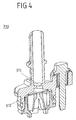
Fig. 4 is a sectional view of a fresh airinflow control valve 310. -
Fig. 5 is a view illustrating flows of a fresh air and a blow-by gas of thecrankcase ventilation device 1000 under a low-speed/middle-speed condition. -
Fig. 6 is a view illustrating flows of a fresh air and a blow-by gas of thecrankcase ventilation device 1000 under a high-speed condition. - The elements constituting the crankcase ventilation device for a vehicle according to the present invention may be integrally used or separately used as occasion demands. Further, some elements may be omitted according to an in-use form.
- A preferred embodiment of the crankcase ventilation device for a vehicle according to the present invention will described with reference to the accompanying drawings. It should be noted that the drawings are not to precise scale and may be exaggerated in thickness of lines or size of components for descriptive convenience and clarity. In addition, terms used herein are defined by taking functions of the present invention into account and can be changed according to user or operator custom or intention. Therefore, definition of the terms should be made according to the overall disclosure set forth herein.
- Hereinafter, an embodiment of the
crankcase ventilation device 1000 for a vehicle according to the present invention will be described with reference to the accompanying drawings. - As illustrated in
Fig. 1 , thecrankcase ventilation device 1000 for a vehicle according to an embodiment of the present invention includes an air cleaner 100 (seeFigs. 5 and6 ), acrankcase 400, acam cover 300 coupled to an upper side of thecrankcase 400, an intake manifold 500 (seeFig. 2 ) coupled to a lateral side of thecrankcase 400, and anair inflow part 200 one side of which is connected to theair cleaner 100 and an opposite side of which is connected to theintake manifold 500. - A turbo charger that compresses and introduces air to increase engine efficiency may be situated between the
air cleaner 100 and the air inflow part 200 (the turbo charger is not illustrated). - The
air cleaner 100 purifies air such that the air mixed with dust and the like is not introduced into thecrankcase 400, and introduces the air into thecrankcase 400. - The
air inflow part 200 includes anair inflow hose 210 and a freshair inflow hose 220. - One side of the
air inflow hose 210 is connected to theair cleaner 100 and an opposite side of theair inflow hose 210 is connected to theintake manifold 500 so that the air purified by theair cleaner 100 is introduced into theintake manifold 500. - Accordingly, the air purified in the
intake manifold 500 is mixed with a blow-by gas and is introduced into thecrankcase 400. - One side of the fresh
air inflow hose 220 is connected to an outer peripheral surface of theair inflow hose 210 and an opposite side of the freshair inflow hose 220 is connected to the fresh airinflow control valve 310 so that the air that is not mixed with the blow-by gas, that is, the fresh air is introduced into thecrankcase 400. - As illustrated in
Fig. 3 , acylinder 410 is situated in the interior of thecrankcase 400, and a cycle of an intake stroke, a combustion stroke, an explosion stroke, and an exhaust stroke is performed while apiston 420 is moved upwards and downwards in thecylinder 410, and then a blow-by gas produced at an upper portion of thecylinder 410 is leaked through an aperture between a wall of thecylinder 410 and thepiston 420 and is introduced into thecrankcase 400. - The
cam cover 300 is coupled to an upper portion of thecrankcase 400 to seal the interior of thecrankcase 400, and includes a fresh airinflow control valve 310, apressure control valve 320, and anoil separator 330. - One side of the fresh air
inflow control valve 310 is connected to the freshair inflow hose 220 and an opposite side of the fresh airinflow control valve 310 is connected to thecam cover 300 so that the fresh air from the freshair inflow hose 220 is introduced into the interior of thecrank case 400. - As illustrated in
Fig. 4 , the fresh airinflow control valve 310 includes anozzle 311 and adiaphragm 312 therein. - The
nozzle 311 is situated inside the fresh airinflow control valve 310 to introduce a suitable amount of fresh air into thecrank case 400. - The
diaphragm 312 has a thin plate that may be opened and closed according to pressure in order to allows air to flow only in one direction and is situated below thenozzle 311, and is closed if a pressure in thecrankcase 400 rises to prevent the blow-by gas in thecrank case 400 from flowing backwards to theair inflow part 200 through the freshair inflow hose 220. - The
pressure control valve 320 is situated on the upper side of thecam cover 300 and is communicated between thecrank case 400 and theintake manifold 500 so that a change in the internal pressure of thecrank case 400 is controlled according to a turbo charging pressure of the compressed air introduced from the turbo charger (not illustrated) according to a pressure difference between opposite sides of thepressure control valve 320 and a load of the engine. - Accordingly, the
pressure control valve 320 is opened and closed according to the change in the internal pressure of theintake manifold 500 to allow the blow-by gas in thecrank case 400 to be introduced into theintake manifold 500. - The
pressure control valve 320 may be an orifice valve, a pressure reducing valve, or a solenoid valve that is electrically connected to an electronic control unit (ECU) that detects a change in pressure. - The
oil separator 330 is communicated with thepressure control valve 320 to separate engine oil particles mixed with the blow-by gas introduced into thecrank case 400. - As illustrated in
Fig. 1 , two pipes are provided at an upper portion of the crankcase ventilation device such that arecirculation hose 331 is connected to one of the pipes to introduce the blow-by gas, from which engine oil is separated, into theair inflow part 200 so that the introduced blow-by gas is mixed with fresh air and is introduced into theintake manifold 500 and abypass hose 332 is connected to the other of the pipes to directly introduce the blow-by gas into theintake manifold 500. - Furthermore, when the turbo charger (not illustrated) is installed, the blow-by gas introduced from the
recirculation hose 331 into theair flow part 200 is mixed with the compressed air introduced from the turbo charger and is introduced into theintake manifold 500. - Hereinafter, the flows of the fresh air and the blow-by gas in the
crankcase ventilation device 100 according to an engine condition will be described with reference toFigs. 5 and6 . - First, the flows of the fresh air and the blow-by gas in a low-speed/middle-speed condition will be described with reference to
Fig. 5 . - Here, the "low-speed/middle-speed condition" refers to a state in which a partial load is applied to the engine, and means a state in which a throttle that adjusts an amount of the fuel supplied to the engine is partially opened, that is, a partial throttle state and does not mean that the speed of the vehicle itself is a low speed or a middle speed.
- In this condition, because the amount of generated blow-by gas is not large, the pressure in the
crankcase 400 does not significantly rise so that thepressure control valve 320 is slightly opened, and the blow-by gas in thecrankcase 400 flows to theintake manifold 500 and is mixed with the fresh air introduced from theair inflow hose 210 in theintake manifold 500 to be reintroduced into thecrankcase 400 and burned again. - The fresh air is introduced into the
crankcase 400 through the fresh airinflow control valve 310. - Next, the flows of the fresh air and the blow-by gas at a high-speed condition will be described with reference to
Fig. 6 . - Here, the "high-speed condition" refers to a state in which a full load is applied to the engine, and means a state in which the throttle is completely opened, that is, a full throttle state.
- In this condition, because the amount of the blow-by gas increases, the pressure in the
crankcase 400 significantly rises, and thepressure control valve 320 is opened by a large degree and the flow rate of the blow-by gas introduced into theintake manifold 500 increases in thecrankcase 400. - Accordingly, the blow-by gas in the
crankcase 400 is not entirely introduced into theintake manifold 400, but flows backwards to the freshair inflow hose 220. - Then, the
diaphragm 312 in the interior of the fresh airinflow control valve 310 situated in thecam cover 300 prevents the backward flow phenomenon so that the blow-by gas is introduced only to theintake manifold 500. - Although the embodiment of the present invention illustrated in the drawings has been described so that those skilled in the art can easily reproduce and implement the present invention, it is merely exemplary and it will be understood by those skilled in the art that various modifications and equivalent embodiments can be made. Therefore, the scope of the present invention should be determined according to the claims.
Claims (7)
- A crankcase ventilation device for a vehicle comprising:a crankcase (400);a cam cover (300) situated on the upper side of the crank case (400);a fresh air inflow control valve (310) one side of which is connected to the cam cover (300) and an opposite side of which is connected to a fresh air inflow hose (220) so that fresh air is introduced into the crank case (400); anda pressure control valve (320) situated on the upper side of the cam cover (300) to control a pressure in the crankcase (400).
- The crankcase ventilation device according to claim 1, wherein a nozzle (311) is situated in the interior of the fresh air inflow hose (220) of the fresh air inflow control valve (310), and the nozzle (311) controls inflows of the fresh air into the crankcase (400) according to a control of the pressure in the crankcase (400) of the pressure control valve (320).
- The crankcase ventilation device according to claim 2, wherein a diaphragm (312) is situated on the lower side of the nozzle (311) to prevent backward flows of a blow-by gas to the fresh air inflow hose (220).
- The crankcase ventilation device according to claim 3, further comprising:an oil separator (330) communicated with the pressure control valve (320) to separate oil particles from the blow-by gas discharged from the crank case (400).
- The crankcase ventilation device according to claim 4, wherein the pressure control valve (320) is any one of an orifice valve, a pressure reducing valve, and a solenoid valve electrically connected to an ECU.
- The crankcase ventilation device according to any one of clams 1 to 5, wherein in a low-speed/middle-speed of an engine provided with the crankcase ventilation device for a vehicle, the pressure control valve (320) is opened according to the amount of generated blow-by gas in the crankcase (400) such that the blow-by gas in the crankcase (400) flows into an intake manifold (500) and is mixed with the fresh air supplied from the air inflow hose (210) to be reintroduced into the crankcase (400) and burned again, and the fresh air is introduced into the crankcase (400) through the fresh air inflow control valve (310).
- The crankcase ventilation device according to any one of clams 1 to 5, wherein in a high-speed condition of an engine provided with the crankcase ventilation device for a vehicle, the amount of the blow-by gas in the crankcase (400) increases so that when the blow-by gas is introduced into the fresh air inflow hose (220), the blow-by gas is prevented from being introduced into the fresh air inflow hose (220) through the fresh air inflow control valve (310).
Applications Claiming Priority (2)
| Application Number | Priority Date | Filing Date | Title |
|---|---|---|---|
| KR1020130108714A KR101496034B1 (en) | 2013-09-10 | 2013-09-10 | A Device of closed crankcase ventilation for vehicle |
| PCT/KR2014/008231 WO2015037862A1 (en) | 2013-09-10 | 2014-09-03 | Crankcase ventilation device for vehicle |
Publications (3)
| Publication Number | Publication Date |
|---|---|
| EP3045692A1 true EP3045692A1 (en) | 2016-07-20 |
| EP3045692A4 EP3045692A4 (en) | 2017-06-14 |
| EP3045692B1 EP3045692B1 (en) | 2018-08-22 |
Family
ID=52594468
Family Applications (1)
| Application Number | Title | Priority Date | Filing Date |
|---|---|---|---|
| EP14844241.1A Not-in-force EP3045692B1 (en) | 2013-09-10 | 2014-09-03 | Crankcase ventilation device for vehicle |
Country Status (5)
| Country | Link |
|---|---|
| US (1) | US9995192B2 (en) |
| EP (1) | EP3045692B1 (en) |
| KR (1) | KR101496034B1 (en) |
| CN (1) | CN105518260B (en) |
| WO (1) | WO2015037862A1 (en) |
Cited By (1)
| Publication number | Priority date | Publication date | Assignee | Title |
|---|---|---|---|---|
| EP3839222A1 (en) * | 2019-12-20 | 2021-06-23 | Kubota Corporation | Ventilator-equipped engine |
Families Citing this family (2)
| Publication number | Priority date | Publication date | Assignee | Title |
|---|---|---|---|---|
| CN106050360A (en) * | 2016-08-04 | 2016-10-26 | 广西玉柴机器股份有限公司 | Ventilation device ventilating crank case forcibly |
| KR102572239B1 (en) * | 2021-06-30 | 2023-08-30 | 인지컨트롤스 주식회사 | Ventilation structure of internal combustion engine |
Family Cites Families (37)
| Publication number | Priority date | Publication date | Assignee | Title |
|---|---|---|---|---|
| GB1406303A (en) * | 1971-12-01 | 1975-09-17 | Gen Motors Holdens Pty Ltd | Crankcase ventilator valve |
| FR2563572B1 (en) * | 1984-04-27 | 1991-05-31 | Kubota Ltd | VALVE OPERATION SYSTEM OF A HEAD VALVE ENGINE |
| JPH0610110Y2 (en) | 1987-06-04 | 1994-03-16 | 日産自動車株式会社 | Blow-by gas reduction device for dry sump refueling engine |
| JPH09303128A (en) | 1996-05-15 | 1997-11-25 | Toyota Motor Corp | Blow-by gas recirculation device |
| JPH1162564A (en) | 1997-08-08 | 1999-03-05 | Yamaha Motor Co Ltd | Internal combustion engine |
| JP4323203B2 (en) * | 2003-04-07 | 2009-09-02 | 愛知機械工業株式会社 | Blowby gas recirculation device for internal combustion engine |
| JP4502737B2 (en) * | 2003-08-29 | 2010-07-14 | 本田技研工業株式会社 | Blow-by gas ventilation system for internal combustion engines |
| JP2006250080A (en) * | 2005-03-11 | 2006-09-21 | Toyota Motor Corp | Internal combustion engine with blowby gas treatment device |
| CN2823564Y (en) * | 2005-08-09 | 2006-10-04 | 比亚迪股份有限公司 | Forced ventilator for crankcase of automobile engine |
| KR101163786B1 (en) | 2005-12-09 | 2012-07-09 | 현대자동차주식회사 | positive crankcase ventilation valve |
| JP4297175B2 (en) * | 2006-10-06 | 2009-07-15 | トヨタ自動車株式会社 | Blow-by gas processing equipment |
| JP2008106637A (en) * | 2006-10-24 | 2008-05-08 | Aisan Ind Co Ltd | Blowby gas passage structure |
| DE102006054117B4 (en) | 2006-11-15 | 2021-03-11 | Hengst Se | Crankcase ventilation of an internal combustion engine controlled in partial and full load operation |
| DE202006017813U1 (en) * | 2006-11-23 | 2008-03-27 | Hengst Gmbh & Co.Kg | Internal combustion engine with a crankcase ventilation line |
| DE102006058072A1 (en) * | 2006-12-07 | 2008-06-19 | Mahle International Gmbh | crankcase ventilation |
| JP4321606B2 (en) * | 2007-02-28 | 2009-08-26 | トヨタ自動車株式会社 | Blow-by gas reduction device, cylinder head used in the blow-by gas reduction device, and internal combustion engine including the blow-by gas reduction device |
| US7562652B2 (en) * | 2007-03-12 | 2009-07-21 | Gm Global Technology Operations, Inc. | Engine PCV system with hydrophobic, oleophobic membrane for air/oil separation |
| JP4748152B2 (en) * | 2007-12-27 | 2011-08-17 | トヨタ自動車株式会社 | Intake pipe structure of internal combustion engine |
| US8151775B2 (en) | 2008-10-10 | 2012-04-10 | GM Global Technology Operations LLC | High vacuum crankcase ventilation |
| JP5134501B2 (en) * | 2008-10-28 | 2013-01-30 | 三菱重工業株式会社 | Gas engine lubrication system |
| JP4793453B2 (en) * | 2009-02-04 | 2011-10-12 | トヨタ自動車株式会社 | Control device for internal combustion engine |
| CN101608562B (en) * | 2009-06-30 | 2011-08-10 | 奇瑞汽车股份有限公司 | Two-way gas flow control valve and ventilation system of crankcase of engine |
| JP5478399B2 (en) * | 2009-09-30 | 2014-04-23 | 株式会社クボタ | Engine blow-by gas recirculation system |
| JP5289276B2 (en) * | 2009-09-30 | 2013-09-11 | 愛三工業株式会社 | Blow-by gas reduction device |
| JP5412231B2 (en) * | 2009-10-19 | 2014-02-12 | 本田技研工業株式会社 | Engine with breather mechanism |
| JP5459500B2 (en) * | 2010-05-18 | 2014-04-02 | スズキ株式会社 | Engine blow-by gas processing equipment |
| JP5873636B2 (en) * | 2011-02-14 | 2016-03-01 | 株式会社マキタ | engine |
| JP5717511B2 (en) * | 2011-04-01 | 2015-05-13 | 愛三工業株式会社 | Blow-by gas reduction device for supercharged engine |
| CN202081932U (en) * | 2011-04-28 | 2011-12-21 | 长城汽车股份有限公司 | Pressure adjusting system of supercharged engine crankcase of automobile |
| JP5847445B2 (en) * | 2011-06-08 | 2016-01-20 | 株式会社マーレ フィルターシステムズ | Oil separator for internal combustion engine |
| JP2013096247A (en) * | 2011-10-28 | 2013-05-20 | Toyota Motor Corp | Control device of internal combustion engine |
| CN103906901B (en) * | 2011-10-31 | 2016-04-27 | 丰田自动车株式会社 | The air-changing control device of internal-combustion engine |
| JP5962171B2 (en) * | 2012-04-24 | 2016-08-03 | スズキ株式会社 | Combustion state control device for internal combustion engine of vehicle |
| US9091239B2 (en) * | 2012-07-25 | 2015-07-28 | Makita Corporation | Engine having displaceable elastic film |
| US9181883B2 (en) * | 2013-01-18 | 2015-11-10 | Nagesh S. Mavinahally | Four cycle engine carburetors |
| CN103256099A (en) * | 2013-02-22 | 2013-08-21 | 浙江吉利汽车研究院有限公司杭州分公司 | Electric crankcase ventilation system |
| US10533470B2 (en) * | 2013-11-08 | 2020-01-14 | Honda Motor Co., Ltd. | Oil separation device for internal combustion engine |
-
2013
- 2013-09-10 KR KR1020130108714A patent/KR101496034B1/en not_active Expired - Fee Related
-
2014
- 2014-09-03 CN CN201480049503.6A patent/CN105518260B/en not_active Expired - Fee Related
- 2014-09-03 EP EP14844241.1A patent/EP3045692B1/en not_active Not-in-force
- 2014-09-03 US US15/021,265 patent/US9995192B2/en active Active
- 2014-09-03 WO PCT/KR2014/008231 patent/WO2015037862A1/en not_active Ceased
Cited By (2)
| Publication number | Priority date | Publication date | Assignee | Title |
|---|---|---|---|---|
| EP3839222A1 (en) * | 2019-12-20 | 2021-06-23 | Kubota Corporation | Ventilator-equipped engine |
| US11280233B2 (en) | 2019-12-20 | 2022-03-22 | Kubota Corporation | Ventilator-equipped engine |
Also Published As
| Publication number | Publication date |
|---|---|
| WO2015037862A1 (en) | 2015-03-19 |
| CN105518260A (en) | 2016-04-20 |
| US9995192B2 (en) | 2018-06-12 |
| US20160222847A1 (en) | 2016-08-04 |
| EP3045692A4 (en) | 2017-06-14 |
| EP3045692B1 (en) | 2018-08-22 |
| CN105518260B (en) | 2018-06-08 |
| KR101496034B1 (en) | 2015-02-25 |
Similar Documents
| Publication | Publication Date | Title |
|---|---|---|
| US20090301446A1 (en) | Blow-by gas reflux apparatus for engines with superchargers | |
| JP2008111422A (en) | Blow-by gas processing equipment | |
| JP2008121520A (en) | Blow-by gas processing equipment | |
| CN102892982A (en) | Blow-by gas treatment device for engine | |
| CN201284681Y (en) | Engine crankcase ventilation system | |
| CN201826926U (en) | Breathing system of 2.8L turbocharging diesel motor | |
| US20080295814A1 (en) | Internal Combustion Engine | |
| CN202348469U (en) | Integrated type cylinder head cover of gasoline engine | |
| EP3045692B1 (en) | Crankcase ventilation device for vehicle | |
| JP2013096247A (en) | Control device of internal combustion engine | |
| JP6544045B2 (en) | Ventilator for internal combustion engine with supercharger | |
| CN201255026Y (en) | Valve chamber shroud for engine | |
| CN104948262A (en) | Oil-gas separator | |
| JP2009293549A (en) | Crankcase ventilator for internal combustion engine | |
| CN202510187U (en) | Self-sealed oil return structure of blow-by oil and gas separation system of engine crank case | |
| CN202140139U (en) | Ventilating system of engine crankcase | |
| JPS6056890B2 (en) | Blow-by gas treatment device for internal combustion engine with turbo charger | |
| JP2008150956A (en) | Exhaust gas recirculation device for internal combustion engine | |
| JP2013234641A (en) | Intake device of internal combustion engine | |
| JP2010209884A (en) | Blow-by gas treatment device of internal combustion engine | |
| CN201187335Y (en) | Breather of engine | |
| US10151225B2 (en) | Integrated oil separator assembly for crankcase ventilation | |
| CN106285832A (en) | A kind of for Heavy End Aviation Fuel piston-engined crankcase pressure self-balancing system | |
| JP6157147B2 (en) | Blowby gas recirculation system | |
| CN221373739U (en) | Cylinder head cover and engine |
Legal Events
| Date | Code | Title | Description |
|---|---|---|---|
| PUAI | Public reference made under article 153(3) epc to a published international application that has entered the european phase |
Free format text: ORIGINAL CODE: 0009012 |
|
| 17P | Request for examination filed |
Effective date: 20160407 |
|
| AK | Designated contracting states |
Kind code of ref document: A1 Designated state(s): AL AT BE BG CH CY CZ DE DK EE ES FI FR GB GR HR HU IE IS IT LI LT LU LV MC MK MT NL NO PL PT RO RS SE SI SK SM TR |
|
| AX | Request for extension of the european patent |
Extension state: BA ME |
|
| DAX | Request for extension of the european patent (deleted) | ||
| A4 | Supplementary search report drawn up and despatched |
Effective date: 20170512 |
|
| RIC1 | Information provided on ipc code assigned before grant |
Ipc: F01M 13/00 20060101AFI20170508BHEP Ipc: F01M 11/00 20060101ALI20170508BHEP Ipc: F02M 25/06 20160101ALI20170508BHEP Ipc: F01M 13/02 20060101ALI20170508BHEP |
|
| GRAP | Despatch of communication of intention to grant a patent |
Free format text: ORIGINAL CODE: EPIDOSNIGR1 |
|
| INTG | Intention to grant announced |
Effective date: 20180315 |
|
| GRAS | Grant fee paid |
Free format text: ORIGINAL CODE: EPIDOSNIGR3 |
|
| GRAA | (expected) grant |
Free format text: ORIGINAL CODE: 0009210 |
|
| AK | Designated contracting states |
Kind code of ref document: B1 Designated state(s): AL AT BE BG CH CY CZ DE DK EE ES FI FR GB GR HR HU IE IS IT LI LT LU LV MC MK MT NL NO PL PT RO RS SE SI SK SM TR |
|
| REG | Reference to a national code |
Ref country code: GB Ref legal event code: FG4D |
|
| REG | Reference to a national code |
Ref country code: CH Ref legal event code: EP |
|
| REG | Reference to a national code |
Ref country code: FR Ref legal event code: PLFP Year of fee payment: 5 |
|
| REG | Reference to a national code |
Ref country code: AT Ref legal event code: REF Ref document number: 1032782 Country of ref document: AT Kind code of ref document: T Effective date: 20180915 |
|
| REG | Reference to a national code |
Ref country code: IE Ref legal event code: FG4D |
|
| REG | Reference to a national code |
Ref country code: DE Ref legal event code: R096 Ref document number: 602014031078 Country of ref document: DE |
|
| REG | Reference to a national code |
Ref country code: NL Ref legal event code: MP Effective date: 20180822 |
|
| REG | Reference to a national code |
Ref country code: LT Ref legal event code: MG4D |
|
| PG25 | Lapsed in a contracting state [announced via postgrant information from national office to epo] |
Ref country code: GR Free format text: LAPSE BECAUSE OF FAILURE TO SUBMIT A TRANSLATION OF THE DESCRIPTION OR TO PAY THE FEE WITHIN THE PRESCRIBED TIME-LIMIT Effective date: 20181123 Ref country code: SE Free format text: LAPSE BECAUSE OF FAILURE TO SUBMIT A TRANSLATION OF THE DESCRIPTION OR TO PAY THE FEE WITHIN THE PRESCRIBED TIME-LIMIT Effective date: 20180822 Ref country code: NL Free format text: LAPSE BECAUSE OF FAILURE TO SUBMIT A TRANSLATION OF THE DESCRIPTION OR TO PAY THE FEE WITHIN THE PRESCRIBED TIME-LIMIT Effective date: 20180822 Ref country code: BG Free format text: LAPSE BECAUSE OF FAILURE TO SUBMIT A TRANSLATION OF THE DESCRIPTION OR TO PAY THE FEE WITHIN THE PRESCRIBED TIME-LIMIT Effective date: 20181122 Ref country code: LT Free format text: LAPSE BECAUSE OF FAILURE TO SUBMIT A TRANSLATION OF THE DESCRIPTION OR TO PAY THE FEE WITHIN THE PRESCRIBED TIME-LIMIT Effective date: 20180822 Ref country code: FI Free format text: LAPSE BECAUSE OF FAILURE TO SUBMIT A TRANSLATION OF THE DESCRIPTION OR TO PAY THE FEE WITHIN THE PRESCRIBED TIME-LIMIT Effective date: 20180822 Ref country code: RS Free format text: LAPSE BECAUSE OF FAILURE TO SUBMIT A TRANSLATION OF THE DESCRIPTION OR TO PAY THE FEE WITHIN THE PRESCRIBED TIME-LIMIT Effective date: 20180822 Ref country code: IS Free format text: LAPSE BECAUSE OF FAILURE TO SUBMIT A TRANSLATION OF THE DESCRIPTION OR TO PAY THE FEE WITHIN THE PRESCRIBED TIME-LIMIT Effective date: 20181222 Ref country code: NO Free format text: LAPSE BECAUSE OF FAILURE TO SUBMIT A TRANSLATION OF THE DESCRIPTION OR TO PAY THE FEE WITHIN THE PRESCRIBED TIME-LIMIT Effective date: 20181122 |
|
| REG | Reference to a national code |
Ref country code: AT Ref legal event code: MK05 Ref document number: 1032782 Country of ref document: AT Kind code of ref document: T Effective date: 20180822 |
|
| PG25 | Lapsed in a contracting state [announced via postgrant information from national office to epo] |
Ref country code: AL Free format text: LAPSE BECAUSE OF FAILURE TO SUBMIT A TRANSLATION OF THE DESCRIPTION OR TO PAY THE FEE WITHIN THE PRESCRIBED TIME-LIMIT Effective date: 20180822 Ref country code: LV Free format text: LAPSE BECAUSE OF FAILURE TO SUBMIT A TRANSLATION OF THE DESCRIPTION OR TO PAY THE FEE WITHIN THE PRESCRIBED TIME-LIMIT Effective date: 20180822 Ref country code: HR Free format text: LAPSE BECAUSE OF FAILURE TO SUBMIT A TRANSLATION OF THE DESCRIPTION OR TO PAY THE FEE WITHIN THE PRESCRIBED TIME-LIMIT Effective date: 20180822 |
|
| PG25 | Lapsed in a contracting state [announced via postgrant information from national office to epo] |
Ref country code: RO Free format text: LAPSE BECAUSE OF FAILURE TO SUBMIT A TRANSLATION OF THE DESCRIPTION OR TO PAY THE FEE WITHIN THE PRESCRIBED TIME-LIMIT Effective date: 20180822 Ref country code: IT Free format text: LAPSE BECAUSE OF FAILURE TO SUBMIT A TRANSLATION OF THE DESCRIPTION OR TO PAY THE FEE WITHIN THE PRESCRIBED TIME-LIMIT Effective date: 20180822 Ref country code: EE Free format text: LAPSE BECAUSE OF FAILURE TO SUBMIT A TRANSLATION OF THE DESCRIPTION OR TO PAY THE FEE WITHIN THE PRESCRIBED TIME-LIMIT Effective date: 20180822 Ref country code: AT Free format text: LAPSE BECAUSE OF FAILURE TO SUBMIT A TRANSLATION OF THE DESCRIPTION OR TO PAY THE FEE WITHIN THE PRESCRIBED TIME-LIMIT Effective date: 20180822 Ref country code: ES Free format text: LAPSE BECAUSE OF FAILURE TO SUBMIT A TRANSLATION OF THE DESCRIPTION OR TO PAY THE FEE WITHIN THE PRESCRIBED TIME-LIMIT Effective date: 20180822 Ref country code: CZ Free format text: LAPSE BECAUSE OF FAILURE TO SUBMIT A TRANSLATION OF THE DESCRIPTION OR TO PAY THE FEE WITHIN THE PRESCRIBED TIME-LIMIT Effective date: 20180822 Ref country code: PL Free format text: LAPSE BECAUSE OF FAILURE TO SUBMIT A TRANSLATION OF THE DESCRIPTION OR TO PAY THE FEE WITHIN THE PRESCRIBED TIME-LIMIT Effective date: 20180822 |
|
| REG | Reference to a national code |
Ref country code: CH Ref legal event code: PL |
|
| REG | Reference to a national code |
Ref country code: DE Ref legal event code: R097 Ref document number: 602014031078 Country of ref document: DE |
|
| PG25 | Lapsed in a contracting state [announced via postgrant information from national office to epo] |
Ref country code: SK Free format text: LAPSE BECAUSE OF FAILURE TO SUBMIT A TRANSLATION OF THE DESCRIPTION OR TO PAY THE FEE WITHIN THE PRESCRIBED TIME-LIMIT Effective date: 20180822 Ref country code: DK Free format text: LAPSE BECAUSE OF FAILURE TO SUBMIT A TRANSLATION OF THE DESCRIPTION OR TO PAY THE FEE WITHIN THE PRESCRIBED TIME-LIMIT Effective date: 20180822 Ref country code: SM Free format text: LAPSE BECAUSE OF FAILURE TO SUBMIT A TRANSLATION OF THE DESCRIPTION OR TO PAY THE FEE WITHIN THE PRESCRIBED TIME-LIMIT Effective date: 20180822 |
|
| REG | Reference to a national code |
Ref country code: BE Ref legal event code: MM Effective date: 20180930 |
|
| REG | Reference to a national code |
Ref country code: IE Ref legal event code: MM4A |
|
| PG25 | Lapsed in a contracting state [announced via postgrant information from national office to epo] |
Ref country code: LU Free format text: LAPSE BECAUSE OF NON-PAYMENT OF DUE FEES Effective date: 20180903 Ref country code: MC Free format text: LAPSE BECAUSE OF FAILURE TO SUBMIT A TRANSLATION OF THE DESCRIPTION OR TO PAY THE FEE WITHIN THE PRESCRIBED TIME-LIMIT Effective date: 20180822 |
|
| PLBE | No opposition filed within time limit |
Free format text: ORIGINAL CODE: 0009261 |
|
| STAA | Information on the status of an ep patent application or granted ep patent |
Free format text: STATUS: NO OPPOSITION FILED WITHIN TIME LIMIT |
|
| 26N | No opposition filed |
Effective date: 20190523 |
|
| PG25 | Lapsed in a contracting state [announced via postgrant information from national office to epo] |
Ref country code: IE Free format text: LAPSE BECAUSE OF NON-PAYMENT OF DUE FEES Effective date: 20180903 |
|
| PG25 | Lapsed in a contracting state [announced via postgrant information from national office to epo] |
Ref country code: CH Free format text: LAPSE BECAUSE OF NON-PAYMENT OF DUE FEES Effective date: 20180930 Ref country code: LI Free format text: LAPSE BECAUSE OF NON-PAYMENT OF DUE FEES Effective date: 20180930 Ref country code: SI Free format text: LAPSE BECAUSE OF FAILURE TO SUBMIT A TRANSLATION OF THE DESCRIPTION OR TO PAY THE FEE WITHIN THE PRESCRIBED TIME-LIMIT Effective date: 20180822 Ref country code: BE Free format text: LAPSE BECAUSE OF NON-PAYMENT OF DUE FEES Effective date: 20180930 |
|
| PG25 | Lapsed in a contracting state [announced via postgrant information from national office to epo] |
Ref country code: MT Free format text: LAPSE BECAUSE OF NON-PAYMENT OF DUE FEES Effective date: 20180903 |
|
| PG25 | Lapsed in a contracting state [announced via postgrant information from national office to epo] |
Ref country code: TR Free format text: LAPSE BECAUSE OF FAILURE TO SUBMIT A TRANSLATION OF THE DESCRIPTION OR TO PAY THE FEE WITHIN THE PRESCRIBED TIME-LIMIT Effective date: 20180822 |
|
| PG25 | Lapsed in a contracting state [announced via postgrant information from national office to epo] |
Ref country code: PT Free format text: LAPSE BECAUSE OF FAILURE TO SUBMIT A TRANSLATION OF THE DESCRIPTION OR TO PAY THE FEE WITHIN THE PRESCRIBED TIME-LIMIT Effective date: 20180822 |
|
| PG25 | Lapsed in a contracting state [announced via postgrant information from national office to epo] |
Ref country code: HU Free format text: LAPSE BECAUSE OF FAILURE TO SUBMIT A TRANSLATION OF THE DESCRIPTION OR TO PAY THE FEE WITHIN THE PRESCRIBED TIME-LIMIT; INVALID AB INITIO Effective date: 20140903 Ref country code: MK Free format text: LAPSE BECAUSE OF NON-PAYMENT OF DUE FEES Effective date: 20180822 Ref country code: CY Free format text: LAPSE BECAUSE OF FAILURE TO SUBMIT A TRANSLATION OF THE DESCRIPTION OR TO PAY THE FEE WITHIN THE PRESCRIBED TIME-LIMIT Effective date: 20180822 |
|
| PGFP | Annual fee paid to national office [announced via postgrant information from national office to epo] |
Ref country code: FR Payment date: 20210913 Year of fee payment: 8 |
|
| PGFP | Annual fee paid to national office [announced via postgrant information from national office to epo] |
Ref country code: GB Payment date: 20210907 Year of fee payment: 8 Ref country code: DE Payment date: 20210908 Year of fee payment: 8 |
|
| REG | Reference to a national code |
Ref country code: DE Ref legal event code: R119 Ref document number: 602014031078 Country of ref document: DE |
|
| GBPC | Gb: european patent ceased through non-payment of renewal fee |
Effective date: 20220903 |
|
| PG25 | Lapsed in a contracting state [announced via postgrant information from national office to epo] |
Ref country code: FR Free format text: LAPSE BECAUSE OF NON-PAYMENT OF DUE FEES Effective date: 20220930 Ref country code: DE Free format text: LAPSE BECAUSE OF NON-PAYMENT OF DUE FEES Effective date: 20230401 |
|
| PG25 | Lapsed in a contracting state [announced via postgrant information from national office to epo] |
Ref country code: GB Free format text: LAPSE BECAUSE OF NON-PAYMENT OF DUE FEES Effective date: 20220903 |