EP3045341A1 - Indicator gauge in ring - Google Patents
Indicator gauge in ring Download PDFInfo
- Publication number
- EP3045341A1 EP3045341A1 EP16151543.2A EP16151543A EP3045341A1 EP 3045341 A1 EP3045341 A1 EP 3045341A1 EP 16151543 A EP16151543 A EP 16151543A EP 3045341 A1 EP3045341 A1 EP 3045341A1
- Authority
- EP
- European Patent Office
- Prior art keywords
- indicator gauge
- light
- gauge assembly
- trim
- assembly
- Prior art date
- Legal status (The legal status is an assumption and is not a legal conclusion. Google has not performed a legal analysis and makes no representation as to the accuracy of the status listed.)
- Withdrawn
Links
Images


Classifications
-
- G—PHYSICS
- G01—MEASURING; TESTING
- G01D—MEASURING NOT SPECIALLY ADAPTED FOR A SPECIFIC VARIABLE; ARRANGEMENTS FOR MEASURING TWO OR MORE VARIABLES NOT COVERED IN A SINGLE OTHER SUBCLASS; TARIFF METERING APPARATUS; MEASURING OR TESTING NOT OTHERWISE PROVIDED FOR
- G01D11/00—Component parts of measuring arrangements not specially adapted for a specific variable
- G01D11/28—Structurally-combined illuminating devices
-
- B—PERFORMING OPERATIONS; TRANSPORTING
- B60—VEHICLES IN GENERAL
- B60K—ARRANGEMENT OR MOUNTING OF PROPULSION UNITS OR OF TRANSMISSIONS IN VEHICLES; ARRANGEMENT OR MOUNTING OF PLURAL DIVERSE PRIME-MOVERS IN VEHICLES; AUXILIARY DRIVES FOR VEHICLES; INSTRUMENTATION OR DASHBOARDS FOR VEHICLES; ARRANGEMENTS IN CONNECTION WITH COOLING, AIR INTAKE, GAS EXHAUST OR FUEL SUPPLY OF PROPULSION UNITS IN VEHICLES
- B60K35/00—Instruments specially adapted for vehicles; Arrangement of instruments in or on vehicles
- B60K35/60—Instruments characterised by their location or relative disposition in or on vehicles
-
- B—PERFORMING OPERATIONS; TRANSPORTING
- B60—VEHICLES IN GENERAL
- B60K—ARRANGEMENT OR MOUNTING OF PROPULSION UNITS OR OF TRANSMISSIONS IN VEHICLES; ARRANGEMENT OR MOUNTING OF PLURAL DIVERSE PRIME-MOVERS IN VEHICLES; AUXILIARY DRIVES FOR VEHICLES; INSTRUMENTATION OR DASHBOARDS FOR VEHICLES; ARRANGEMENTS IN CONNECTION WITH COOLING, AIR INTAKE, GAS EXHAUST OR FUEL SUPPLY OF PROPULSION UNITS IN VEHICLES
- B60K35/00—Instruments specially adapted for vehicles; Arrangement of instruments in or on vehicles
- B60K35/20—Output arrangements, i.e. from vehicle to user, associated with vehicle functions or specially adapted therefor
- B60K35/21—Output arrangements, i.e. from vehicle to user, associated with vehicle functions or specially adapted therefor using visual output, e.g. blinking lights or matrix displays
- B60K35/215—Output arrangements, i.e. from vehicle to user, associated with vehicle functions or specially adapted therefor using visual output, e.g. blinking lights or matrix displays characterised by the combination of multiple visual outputs, e.g. combined instruments with analogue meters and additional displays
-
- B—PERFORMING OPERATIONS; TRANSPORTING
- B60—VEHICLES IN GENERAL
- B60K—ARRANGEMENT OR MOUNTING OF PROPULSION UNITS OR OF TRANSMISSIONS IN VEHICLES; ARRANGEMENT OR MOUNTING OF PLURAL DIVERSE PRIME-MOVERS IN VEHICLES; AUXILIARY DRIVES FOR VEHICLES; INSTRUMENTATION OR DASHBOARDS FOR VEHICLES; ARRANGEMENTS IN CONNECTION WITH COOLING, AIR INTAKE, GAS EXHAUST OR FUEL SUPPLY OF PROPULSION UNITS IN VEHICLES
- B60K35/00—Instruments specially adapted for vehicles; Arrangement of instruments in or on vehicles
- B60K35/20—Output arrangements, i.e. from vehicle to user, associated with vehicle functions or specially adapted therefor
- B60K35/21—Output arrangements, i.e. from vehicle to user, associated with vehicle functions or specially adapted therefor using visual output, e.g. blinking lights or matrix displays
- B60K35/22—Display screens
-
- B—PERFORMING OPERATIONS; TRANSPORTING
- B60—VEHICLES IN GENERAL
- B60K—ARRANGEMENT OR MOUNTING OF PROPULSION UNITS OR OF TRANSMISSIONS IN VEHICLES; ARRANGEMENT OR MOUNTING OF PLURAL DIVERSE PRIME-MOVERS IN VEHICLES; AUXILIARY DRIVES FOR VEHICLES; INSTRUMENTATION OR DASHBOARDS FOR VEHICLES; ARRANGEMENTS IN CONNECTION WITH COOLING, AIR INTAKE, GAS EXHAUST OR FUEL SUPPLY OF PROPULSION UNITS IN VEHICLES
- B60K35/00—Instruments specially adapted for vehicles; Arrangement of instruments in or on vehicles
- B60K35/20—Output arrangements, i.e. from vehicle to user, associated with vehicle functions or specially adapted therefor
- B60K35/28—Output arrangements, i.e. from vehicle to user, associated with vehicle functions or specially adapted therefor characterised by the type of the output information, e.g. video entertainment or vehicle dynamics information; characterised by the purpose of the output information, e.g. for attracting the attention of the driver
-
- G—PHYSICS
- G01—MEASURING; TESTING
- G01D—MEASURING NOT SPECIALLY ADAPTED FOR A SPECIFIC VARIABLE; ARRANGEMENTS FOR MEASURING TWO OR MORE VARIABLES NOT COVERED IN A SINGLE OTHER SUBCLASS; TARIFF METERING APPARATUS; MEASURING OR TESTING NOT OTHERWISE PROVIDED FOR
- G01D13/00—Component parts of indicators for measuring arrangements not specially adapted for a specific variable
-
- B—PERFORMING OPERATIONS; TRANSPORTING
- B60—VEHICLES IN GENERAL
- B60K—ARRANGEMENT OR MOUNTING OF PROPULSION UNITS OR OF TRANSMISSIONS IN VEHICLES; ARRANGEMENT OR MOUNTING OF PLURAL DIVERSE PRIME-MOVERS IN VEHICLES; AUXILIARY DRIVES FOR VEHICLES; INSTRUMENTATION OR DASHBOARDS FOR VEHICLES; ARRANGEMENTS IN CONNECTION WITH COOLING, AIR INTAKE, GAS EXHAUST OR FUEL SUPPLY OF PROPULSION UNITS IN VEHICLES
- B60K2360/00—Indexing scheme associated with groups B60K35/00 or B60K37/00 relating to details of instruments or dashboards
- B60K2360/20—Optical features of instruments
- B60K2360/33—Illumination features
- B60K2360/332—Light emitting diodes
-
- B—PERFORMING OPERATIONS; TRANSPORTING
- B60—VEHICLES IN GENERAL
- B60K—ARRANGEMENT OR MOUNTING OF PROPULSION UNITS OR OF TRANSMISSIONS IN VEHICLES; ARRANGEMENT OR MOUNTING OF PLURAL DIVERSE PRIME-MOVERS IN VEHICLES; AUXILIARY DRIVES FOR VEHICLES; INSTRUMENTATION OR DASHBOARDS FOR VEHICLES; ARRANGEMENTS IN CONNECTION WITH COOLING, AIR INTAKE, GAS EXHAUST OR FUEL SUPPLY OF PROPULSION UNITS IN VEHICLES
- B60K2360/00—Indexing scheme associated with groups B60K35/00 or B60K37/00 relating to details of instruments or dashboards
- B60K2360/20—Optical features of instruments
- B60K2360/33—Illumination features
- B60K2360/336—Light guides
-
- B—PERFORMING OPERATIONS; TRANSPORTING
- B60—VEHICLES IN GENERAL
- B60K—ARRANGEMENT OR MOUNTING OF PROPULSION UNITS OR OF TRANSMISSIONS IN VEHICLES; ARRANGEMENT OR MOUNTING OF PLURAL DIVERSE PRIME-MOVERS IN VEHICLES; AUXILIARY DRIVES FOR VEHICLES; INSTRUMENTATION OR DASHBOARDS FOR VEHICLES; ARRANGEMENTS IN CONNECTION WITH COOLING, AIR INTAKE, GAS EXHAUST OR FUEL SUPPLY OF PROPULSION UNITS IN VEHICLES
- B60K2360/00—Indexing scheme associated with groups B60K35/00 or B60K37/00 relating to details of instruments or dashboards
- B60K2360/20—Optical features of instruments
- B60K2360/33—Illumination features
- B60K2360/341—Illumination of dials
-
- B—PERFORMING OPERATIONS; TRANSPORTING
- B60—VEHICLES IN GENERAL
- B60K—ARRANGEMENT OR MOUNTING OF PROPULSION UNITS OR OF TRANSMISSIONS IN VEHICLES; ARRANGEMENT OR MOUNTING OF PLURAL DIVERSE PRIME-MOVERS IN VEHICLES; AUXILIARY DRIVES FOR VEHICLES; INSTRUMENTATION OR DASHBOARDS FOR VEHICLES; ARRANGEMENTS IN CONNECTION WITH COOLING, AIR INTAKE, GAS EXHAUST OR FUEL SUPPLY OF PROPULSION UNITS IN VEHICLES
- B60K2360/00—Indexing scheme associated with groups B60K35/00 or B60K37/00 relating to details of instruments or dashboards
- B60K2360/20—Optical features of instruments
- B60K2360/33—Illumination features
- B60K2360/343—Illumination of matrix displays
- B60K2360/344—Illumination of matrix displays for additionally illuminating mechanical elements, e.g. pointers or control knobs
-
- B—PERFORMING OPERATIONS; TRANSPORTING
- B60—VEHICLES IN GENERAL
- B60K—ARRANGEMENT OR MOUNTING OF PROPULSION UNITS OR OF TRANSMISSIONS IN VEHICLES; ARRANGEMENT OR MOUNTING OF PLURAL DIVERSE PRIME-MOVERS IN VEHICLES; AUXILIARY DRIVES FOR VEHICLES; INSTRUMENTATION OR DASHBOARDS FOR VEHICLES; ARRANGEMENTS IN CONNECTION WITH COOLING, AIR INTAKE, GAS EXHAUST OR FUEL SUPPLY OF PROPULSION UNITS IN VEHICLES
- B60K2360/00—Indexing scheme associated with groups B60K35/00 or B60K37/00 relating to details of instruments or dashboards
- B60K2360/60—Structural details of dashboards or instruments
- B60K2360/68—Features of instruments
- B60K2360/688—Frames or decorative parts
-
- B—PERFORMING OPERATIONS; TRANSPORTING
- B60—VEHICLES IN GENERAL
- B60K—ARRANGEMENT OR MOUNTING OF PROPULSION UNITS OR OF TRANSMISSIONS IN VEHICLES; ARRANGEMENT OR MOUNTING OF PLURAL DIVERSE PRIME-MOVERS IN VEHICLES; AUXILIARY DRIVES FOR VEHICLES; INSTRUMENTATION OR DASHBOARDS FOR VEHICLES; ARRANGEMENTS IN CONNECTION WITH COOLING, AIR INTAKE, GAS EXHAUST OR FUEL SUPPLY OF PROPULSION UNITS IN VEHICLES
- B60K2360/00—Indexing scheme associated with groups B60K35/00 or B60K37/00 relating to details of instruments or dashboards
- B60K2360/60—Structural details of dashboards or instruments
- B60K2360/68—Features of instruments
- B60K2360/695—Dial features
-
- B—PERFORMING OPERATIONS; TRANSPORTING
- B60—VEHICLES IN GENERAL
- B60K—ARRANGEMENT OR MOUNTING OF PROPULSION UNITS OR OF TRANSMISSIONS IN VEHICLES; ARRANGEMENT OR MOUNTING OF PLURAL DIVERSE PRIME-MOVERS IN VEHICLES; AUXILIARY DRIVES FOR VEHICLES; INSTRUMENTATION OR DASHBOARDS FOR VEHICLES; ARRANGEMENTS IN CONNECTION WITH COOLING, AIR INTAKE, GAS EXHAUST OR FUEL SUPPLY OF PROPULSION UNITS IN VEHICLES
- B60K2360/00—Indexing scheme associated with groups B60K35/00 or B60K37/00 relating to details of instruments or dashboards
- B60K2360/60—Structural details of dashboards or instruments
- B60K2360/68—Features of instruments
- B60K2360/698—Pointers of combined instruments
- B60K2360/6992—Light conducting pointers
-
- B—PERFORMING OPERATIONS; TRANSPORTING
- B60—VEHICLES IN GENERAL
- B60K—ARRANGEMENT OR MOUNTING OF PROPULSION UNITS OR OF TRANSMISSIONS IN VEHICLES; ARRANGEMENT OR MOUNTING OF PLURAL DIVERSE PRIME-MOVERS IN VEHICLES; AUXILIARY DRIVES FOR VEHICLES; INSTRUMENTATION OR DASHBOARDS FOR VEHICLES; ARRANGEMENTS IN CONNECTION WITH COOLING, AIR INTAKE, GAS EXHAUST OR FUEL SUPPLY OF PROPULSION UNITS IN VEHICLES
- B60K35/00—Instruments specially adapted for vehicles; Arrangement of instruments in or on vehicles
- B60K35/50—Instruments characterised by their means of attachment to or integration in the vehicle
Definitions
- the present disclosure relates to an indicator gauge assembly for a vehicle, and more particularly, to an indicator gauge assembly that includes a primary gauge and an auxiliary gauge integrated within a trim ring surrounding the primary gauge.
- a vehicle can have one or more indicator gauges, e.g., a speedometer, a tachometer, a fuel gauge, and a battery charge gauge, arranged within an indicator gauge assembly of a dashboard of a vehicle.
- indicator gauges can be configured to display information regarding the operation and status of the vehicle to the occupants of the vehicle.
- vehicles are being designed to include large displays (Liquid Crystal Displays (LCDs), touchscreens, and the like) to display information to the occupants of the vehicle.
- LCDs Liquid Crystal Displays
- touchscreens touchscreens
- an indicator gauge assembly can include at least one primary indicator gauge, a trim member substantially surrounding the at least one primary indicator gauge, and at least one auxiliary indicator gauge arranged within the trim piece member.
- the trim member can include an opaque portion and a transparent portion.
- the at least one auxiliary indicator gauge can be arranged within the transparent portion.
- indicator gauge assembly As previously discussed, it may be desirable to provide a large amount of information to the occupants of a vehicle. Further, vehicle manufacturers are increasingly adding more and larger displays, LCDs, and other forms of indicator gauges to their designs. As larger-sized, and a larger number of, indicator gauges are being added to vehicle designs, it is becoming increasingly important to maximize the utility of the limited amount of available space (e.g., within a dashboard) in which such indicator gauges may be integrated, while also providing an aesthetically pleasing and efficient design. Therefore, it may be desirable to provide an improved indicator gauge assembly that addresses these and other disadvantages of the presently used designs.
- the indicator gauge assembly includes at least one primary indicator gauge, a trim member substantially surrounding the primary indicator gauge, and at least one auxiliary indicator gauge that is arranged within the trim member. Further details of the presented indicator gauge are provided below.
- an indicator gauge assembly 100 can include one or more primary indicator gauges 110.
- One or more trim members 120 can also be included in the indicator gauge assembly 100.
- Each of the trim members 120 can substantially surround a primary indicator gauge 110.
- the trim member 120 is a trim ring that fully surrounds the primary indicator gauge 110, although other forms of the trim member 120 are contemplated and within the scope of the present disclosure.
- the indicator gauge assembly 100 can further include one or more auxiliary indicator gauges 130, 140, as further described below.
- the indicator gauge assembly 100 can also include a display 150, such as a Liquid Crystal Display (LCD).
- the indicator gauge assembly 100 can, e.g., be arranged within a dashboard or similar structure (not shown) of a vehicle (also not shown).
- the primary indicator gauge 110 can be an analog gauge, such as the speedometer shown in FIG. 2 , but other types of indicator gauges are within the scope of the disclosure (such as a tachometer as shown in FIG. 1 ).
- the auxiliary indicator gauge 130 is shown as a fuel gauge that indicates the amount of fuel within the vehicle.
- the primary indicator gauge 110 can include a pointer 112 and a dial member 114.
- the dial member 114 can be composed of one or more layers (two layers are illustrated in FIG. 3 ) and include a plurality of numerical or other indicators.
- the primary indicator gauge 110 can be illuminated, e.g., by being backlit by an illumination source (not shown). In some aspects, the dial member 114 and the pointer 112 are both illuminated in certain operating conditions of the vehicle.
- the indicator gauge assembly 100 can further include a display support member 152, a printed circuit board (PCB) 160, an assembly support member 170, a shade member 180, and a shield 190.
- the display support member 152 can provide mechanical support for, and/or electrical connections to, the display 150.
- the PCB 160 can provide for electrical connections to the remaining components of the indicator gauge assembly 100.
- the PCB 160 can provide a mounting arrangement for one or more light emitting diodes (LEDs) 165 utilized with the auxiliary indicator gauge 130.
- a housing or shade member 180 and/or shield 190 can optionally be included in the indicator gauge assembly 100 to provide proper offset, reduction of glare from external light, and/or protection from manual interference with the indicator gauges.
- the trim member 120 can include an opaque portion 122 and a transparent portion 124.
- the opaque portion 122 can inhibit light transmission, obscure, and/or block light, e.g., from the dial member 114.
- the transparent portion 124 can permit light to be transmitted from behind the trim member 120 to illumination. It should be appreciated that the transparent portion 124 need not be completely transparent in the sense of being clear, but instead can be translucent, partially opaque, etc. so long as light is permitted to be transmitted through the transparent portion 124, whether the light is diffused or otherwise.
- the transparent portion 124 comprises a light guide 126, 128 arranged within an aperture defined by the trim member 120.
- the auxiliary indicator gauge 130 can include a light source that is at least partially arranged within the trim member 120.
- the light source can include one or more light guides 126, 128, and/or one or more LEDs 165,
- a plurality of LEDs 162 can be coupled to, arranged upon, etc. the PCB 160.
- the display support member 152 can define a corresponding plurality of light channels through which light emitted by the LEDs can travel.
- the LEDs 162 can transmit light through the light channels 153 and into a light guide 128.
- the light guide 128 reflects a portion of the light transmitted from the LEDs, thereby illuminating the light guide 128 in the appropriate areas.
- the light guides 126, 128 can be constructed of any known translucent materials, specifically including but not limited to ulexite ("TV rock") or similar material.
- the light guide 128 can comprise a plurality of individual light transmitting members arranged within a support structure.
- the support structure can divide the light guide 128 into discrete portions for illumination and reduce/eliminate "cross-talk" between the LEDs when illuminated.
- the light guide 126 can be constructed of a single light transmitting element. It should be appreciated that the light guide 126 can be constructed with a lower diffusion rate than the light guide 128 such that discrete portions of the light guide 126 can be separately illuminated from other portions.
- Example embodiments are provided so that this disclosure will be thorough, and will fully convey the scope to those who are skilled in the art. Numerous specific details are set forth such as examples of specific components, devices, and methods, to provide a thorough understanding of embodiments of the present disclosure. It will be apparent to those skilled in the art that specific details need not be employed, that example embodiments may be embodied in many different forms and that neither should be construed to limit the scope of the disclosure. In some example embodiments, well-known procedures, well-known device structures, and well-known technologies are not described in detail.
- first, second, third, etc. may be used herein to describe various elements, components, regions, layers and/or sections, these elements, components, regions, layers and/or sections should not be limited by these terms. These terms may be only used to distinguish one element, component, region, layer or section from another region, layer or section. Terms such as “first,” “second,” and other numerical terms when used herein do not imply a sequence or order unless clearly indicated by the context. Thus, a first element, component, region, layer or section discussed below could be termed a second element, component, region, layer or section without departing from the teachings of the example embodiments.
Landscapes
- Engineering & Computer Science (AREA)
- Chemical & Material Sciences (AREA)
- Combustion & Propulsion (AREA)
- Transportation (AREA)
- Mechanical Engineering (AREA)
- Physics & Mathematics (AREA)
- General Physics & Mathematics (AREA)
- Instrument Panels (AREA)
- Indicating Measured Values (AREA)
- Details Of Measuring Devices (AREA)
Abstract
An indicator gauge assembly (100) includes at least one primary indicator gauge (110), a trim member (120) substantially surrounding the at least one primary indicator gauge, and at least one auxiliary indicator gauge (130) arranged within the trim piece member. The trim member can include an opaque portion and a transparent portion. The at least one auxiliary indicator gauge can be arranged within the transparent portion.
Description
- The present disclosure relates to an indicator gauge assembly for a vehicle, and more particularly, to an indicator gauge assembly that includes a primary gauge and an auxiliary gauge integrated within a trim ring surrounding the primary gauge.
- The background description provided herein is for the purpose of generally presenting the context of the disclosure. Work of the presently named inventors, to the extent it is described in this background section, as well as aspects of the description that may not otherwise qualify as prior art at the time of filing, are neither expressly nor impliedly admitted as prior art against the present disclosure.
- A vehicle can have one or more indicator gauges, e.g., a speedometer, a tachometer, a fuel gauge, and a battery charge gauge, arranged within an indicator gauge assembly of a dashboard of a vehicle. These indicator gauges can be configured to display information regarding the operation and status of the vehicle to the occupants of the vehicle. As vehicles become more complex and sophisticated, it may be desirable to provide a large amount of information to the occupants. In some cases, vehicles are being designed to include large displays (Liquid Crystal Displays (LCDs), touchscreens, and the like) to display information to the occupants of the vehicle. There may be, however, a limited amount of available space within a dashboard to include indicator gauges while also maintaining a clean and functional design, especially when a large display is included in the design.
- In various embodiments of the present disclosure, an indicator gauge assembly is disclosed. The indicator gauge assembly can include at least one primary indicator gauge, a trim member substantially surrounding the at least one primary indicator gauge, and at least one auxiliary indicator gauge arranged within the trim piece member. The trim member can include an opaque portion and a transparent portion. The at least one auxiliary indicator gauge can be arranged within the transparent portion.
- Further areas of applicability of the present disclosure will become apparent from the detailed description provided hereinafter. It should be understood that the detailed description and specific examples are intended for purposes of illustration only and are not intended to limit the scope of the disclosure.
- The present disclosure will become more fully understood from the detailed description and the accompanying drawings, wherein:
-
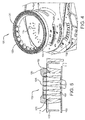
FIG. 1 is a perspective view of an example indicator gauge assembly according to some aspects of the present disclosure; -
FIG. 2 is a front view of a portion of the example indicator gauge assembly ofFIG. 1 ; -
FIG. 3 is an exploded view of the example indicator gauge assembly ofFIG. 1 ; -
FIG. 4 is a partial exploded view of a portion of the example indicator gauge assembly ofFIG. 1 ; and -
FIG. 5 is a sectional view of a portion of the example indicator gauge assembly ofFIG. 1 . - As previously discussed, it may be desirable to provide a large amount of information to the occupants of a vehicle. Further, vehicle manufacturers are increasingly adding more and larger displays, LCDs, and other forms of indicator gauges to their designs. As larger-sized, and a larger number of, indicator gauges are being added to vehicle designs, it is becoming increasingly important to maximize the utility of the limited amount of available space (e.g., within a dashboard) in which such indicator gauges may be integrated, while also providing an aesthetically pleasing and efficient design. Therefore, it may be desirable to provide an improved indicator gauge assembly that addresses these and other disadvantages of the presently used designs.
- Accordingly, an indicator gauge assembly that addresses one or more of the above identified disadvantages is presented. The indicator gauge assembly includes at least one primary indicator gauge, a trim member substantially surrounding the primary indicator gauge, and at least one auxiliary indicator gauge that is arranged within the trim member. Further details of the presented indicator gauge are provided below.
- Referring now to
FIGs. 1 and2 , anindicator gauge assembly 100 can include one or moreprimary indicator gauges 110. One ormore trim members 120 can also be included in theindicator gauge assembly 100. Each of thetrim members 120 can substantially surround aprimary indicator gauge 110. In the illustrated example, thetrim member 120 is a trim ring that fully surrounds theprimary indicator gauge 110, although other forms of thetrim member 120 are contemplated and within the scope of the present disclosure. Theindicator gauge assembly 100 can further include one or moreauxiliary indicator gauges indicator gauge assembly 100 can also include adisplay 150, such as a Liquid Crystal Display (LCD). Theindicator gauge assembly 100 can, e.g., be arranged within a dashboard or similar structure (not shown) of a vehicle (also not shown). - With particular reference to
FIGs. 2 and3 , theprimary indicator gauge 110 can be an analog gauge, such as the speedometer shown inFIG. 2 , but other types of indicator gauges are within the scope of the disclosure (such as a tachometer as shown inFIG. 1 ). Theauxiliary indicator gauge 130 is shown as a fuel gauge that indicates the amount of fuel within the vehicle. Theprimary indicator gauge 110 can include apointer 112 and adial member 114. Thedial member 114 can be composed of one or more layers (two layers are illustrated inFIG. 3 ) and include a plurality of numerical or other indicators. Theprimary indicator gauge 110 can be illuminated, e.g., by being backlit by an illumination source (not shown). In some aspects, thedial member 114 and thepointer 112 are both illuminated in certain operating conditions of the vehicle. - With continuing reference to
FIG. 3 , an exploded view of an exampleindicator gauge assembly 100 according to some aspects of the present disclosure is illustrated. In addition to the components described above, theindicator gauge assembly 100 can further include adisplay support member 152, a printed circuit board (PCB) 160, anassembly support member 170, ashade member 180, and ashield 190. Thedisplay support member 152 can provide mechanical support for, and/or electrical connections to, thedisplay 150. The PCB 160 can provide for electrical connections to the remaining components of theindicator gauge assembly 100. As further described below with reference toFIG. 5 , the PCB 160 can provide a mounting arrangement for one or more light emitting diodes (LEDs) 165 utilized with theauxiliary indicator gauge 130. A housing orshade member 180 and/orshield 190 can optionally be included in theindicator gauge assembly 100 to provide proper offset, reduction of glare from external light, and/or protection from manual interference with the indicator gauges. - Referring now to
FIGs. 4 and 5 , thetrim member 120 can include anopaque portion 122 and atransparent portion 124. Theopaque portion 122 can inhibit light transmission, obscure, and/or block light, e.g., from thedial member 114. Conversely, thetransparent portion 124 can permit light to be transmitted from behind thetrim member 120 to illumination. It should be appreciated that thetransparent portion 124 need not be completely transparent in the sense of being clear, but instead can be translucent, partially opaque, etc. so long as light is permitted to be transmitted through thetransparent portion 124, whether the light is diffused or otherwise. In some aspects, thetransparent portion 124 comprises alight guide trim member 120. - The
auxiliary indicator gauge 130 can include a light source that is at least partially arranged within thetrim member 120. The light source can include one or morelight guides - With particular reference to
FIG. 5 , a plurality ofLEDs 162 can be coupled to, arranged upon, etc. thePCB 160. Thedisplay support member 152 can define a corresponding plurality of light channels through which light emitted by the LEDs can travel. When illuminated, theLEDs 162 can transmit light through thelight channels 153 and into alight guide 128. In some aspects, thelight guide 128 reflects a portion of the light transmitted from the LEDs, thereby illuminating thelight guide 128 in the appropriate areas. Thelight guides - As shown in
FIG. 4 , thelight guide 128 can comprise a plurality of individual light transmitting members arranged within a support structure. In this manner, the support structure can divide thelight guide 128 into discrete portions for illumination and reduce/eliminate "cross-talk" between the LEDs when illuminated. In an alternative aspect, thelight guide 126 can be constructed of a single light transmitting element. It should be appreciated that thelight guide 126 can be constructed with a lower diffusion rate than thelight guide 128 such that discrete portions of thelight guide 126 can be separately illuminated from other portions. - Example embodiments are provided so that this disclosure will be thorough, and will fully convey the scope to those who are skilled in the art. Numerous specific details are set forth such as examples of specific components, devices, and methods, to provide a thorough understanding of embodiments of the present disclosure. It will be apparent to those skilled in the art that specific details need not be employed, that example embodiments may be embodied in many different forms and that neither should be construed to limit the scope of the disclosure. In some example embodiments, well-known procedures, well-known device structures, and well-known technologies are not described in detail.
- The terminology used herein is for the purpose of describing particular example embodiments only and is not intended to be limiting. As used herein, the singular forms "a," "an," and "the" may be intended to include the plural forms as well, unless the context clearly indicates otherwise. The term "and/or" includes any and all combinations of one or more of the associated listed items. The terms "comprises," "comprising," "including," and "having," are inclusive and therefore specify the presence of stated features, integers, steps, operations, elements, and/or components, but do not preclude the presence or addition of one or more other features, integers, steps, operations, elements, components, and/or groups thereof. The method steps, processes, and operations described herein are not to be construed as necessarily requiring their performance in the particular order discussed or illustrated, unless specifically identified as an order of performance. It is also to be understood that additional or alternative steps may be employed.
- Although the terms first, second, third, etc. may be used herein to describe various elements, components, regions, layers and/or sections, these elements, components, regions, layers and/or sections should not be limited by these terms. These terms may be only used to distinguish one element, component, region, layer or section from another region, layer or section. Terms such as "first," "second," and other numerical terms when used herein do not imply a sequence or order unless clearly indicated by the context. Thus, a first element, component, region, layer or section discussed below could be termed a second element, component, region, layer or section without departing from the teachings of the example embodiments.
- The foregoing description of the embodiments has been provided for purposes of illustration and description. It is not intended to be exhaustive or to limit the disclosure. Individual elements or features of a particular embodiment are generally not limited to that particular embodiment, but, where applicable, are interchangeable and can be used in a selected embodiment, even if not specifically shown or described. The same may also be varied in many ways. Such variations are not to be regarded as a departure from the disclosure, and all such modifications are intended to be included within the scope of the disclosure.
Claims (15)
- An indicator gauge assembly for a vehicle, comprising:at least one primary indicator gauge;a trim member substantially surrounding the at least one primary indicator gauge; andat least one auxiliary indicator gauge arranged within the trim member.
- The indicator gauge assembly of claim 1, wherein the trim member is a ring.
- The indicator gauge assembly of claim 1, wherein the trim member comprises:an opaque portion; anda transparent portion,wherein the at least one auxiliary indicator gauge is arranged within the transparent portion.
- The indicator gauge assembly of claim 4, wherein the transparent portion comprises a light guide arranged within an aperture defined by the trim member.
- The indicator gauge assembly of claim 1, wherein the at least one auxiliary indicator gauge comprises:a plurality of light emitting diodes (LEDs); anda light guide arranged within the trim member,wherein the plurality of LEDs are configured to transmit light to the light guide.
- The indicator gauge assembly of claim 1, wherein the at least one primary indicator gauge is an analog gauge.
- An indicator gauge assembly for an instrument panel of a vehicle, comprising:a display configured to display information corresponding to operation of the vehicle;at least one primary indicator gauge;a trim ring substantially surrounding the at least one primary indicator gauge, the trim ring including an opaque portion configured to inhibit light transmission and a transparent portion configured to permit light transmission; andat least one auxiliary indicator gauge arranged within the trim ring, the at least one auxiliary indicator gauge comprising a light source at least partially arranged within the transparent portion of the trim ring.
- The indicator gauge assembly of claim 7, wherein the light source further comprises a light guide constructed of translucent material.
- The indicator gauge assembly of claim 8, wherein the light source comprises one or more light emitting diodes (LEDs).
- The indicator gauge assembly of claim 9, further comprising a display support member defining a plurality of light channels, wherein the display is coupled with the display support member, the trim ring is arranged on the display support member, and the plurality of light channels are configured to transmit light from the one or more LEDs to the light guide.
- The indicator gauge assembly of claim 7, further comprising a display support member defining a plurality of light channels, wherein the display is coupled with the display support member, the trim ring is arranged on the display support member, and the plurality of light channels are configured to transmit light from the light source.
- The indicator gauge assembly of claim 7, wherein the display comprises a Liquid Crystal Display.
- The indicator gauge assembly of claim 7, wherein the transparent portion of the trim ring comprises an aperture defined within the trim ring.
- The indicator gauge assembly of claim 7, further comprising a printed circuit board that provides electrical connections to light source.
- The indicator gauge assembly of claim 7, wherein the at least one primary indicator gauge is an analog gauge.
Applications Claiming Priority (2)
| Application Number | Priority Date | Filing Date | Title |
|---|---|---|---|
| US201562104370P | 2015-01-16 | 2015-01-16 | |
| US14/995,577 US20160209250A1 (en) | 2015-01-16 | 2016-01-14 | Indicator gauge in ring |
Publications (1)
| Publication Number | Publication Date |
|---|---|
| EP3045341A1 true EP3045341A1 (en) | 2016-07-20 |
Family
ID=55174554
Family Applications (1)
| Application Number | Title | Priority Date | Filing Date |
|---|---|---|---|
| EP16151543.2A Withdrawn EP3045341A1 (en) | 2015-01-16 | 2016-01-15 | Indicator gauge in ring |
Country Status (3)
| Country | Link |
|---|---|
| US (1) | US20160209250A1 (en) |
| EP (1) | EP3045341A1 (en) |
| JP (1) | JP2016133511A (en) |
Cited By (1)
| Publication number | Priority date | Publication date | Assignee | Title |
|---|---|---|---|---|
| EP3342621A1 (en) * | 2017-01-02 | 2018-07-04 | Visteon Global Technologies, Inc. | Selective lighting for graphical elements of a gauge |
Families Citing this family (4)
| Publication number | Priority date | Publication date | Assignee | Title |
|---|---|---|---|---|
| JP6201810B2 (en) * | 2014-02-26 | 2017-09-27 | 日本精機株式会社 | Vehicle display device |
| ITUB20153423A1 (en) * | 2015-09-04 | 2017-03-04 | Ferrari Spa | INSTRUMENT PANEL FOR A ROAD VEHICLE |
| JP6628635B2 (en) * | 2016-02-24 | 2020-01-15 | マレリ株式会社 | Vehicle instrumentation |
| US10829039B2 (en) * | 2019-02-18 | 2020-11-10 | Visteon Global Technologies, Inc. | Display arrangement for an instrument cluster |
Citations (4)
| Publication number | Priority date | Publication date | Assignee | Title |
|---|---|---|---|---|
| EP1013496A2 (en) * | 1998-12-23 | 2000-06-28 | Mannesmann VDO Aktiengesellschaft | Display apparatus |
| DE102008001508A1 (en) * | 2007-05-09 | 2008-11-13 | Visteon Global Technologies, Inc., Van Buren Township | Lens for dimensional highlighting |
| JP2010256197A (en) * | 2009-04-27 | 2010-11-11 | Nippon Seiki Co Ltd | Display device |
| EP2676829A1 (en) * | 2012-06-19 | 2013-12-25 | Johnson Controls Automotive Electronics SAS | Carrier assembly for an instrument cluster |
-
2016
- 2016-01-14 US US14/995,577 patent/US20160209250A1/en not_active Abandoned
- 2016-01-15 EP EP16151543.2A patent/EP3045341A1/en not_active Withdrawn
- 2016-01-15 JP JP2016005987A patent/JP2016133511A/en active Pending
Patent Citations (4)
| Publication number | Priority date | Publication date | Assignee | Title |
|---|---|---|---|---|
| EP1013496A2 (en) * | 1998-12-23 | 2000-06-28 | Mannesmann VDO Aktiengesellschaft | Display apparatus |
| DE102008001508A1 (en) * | 2007-05-09 | 2008-11-13 | Visteon Global Technologies, Inc., Van Buren Township | Lens for dimensional highlighting |
| JP2010256197A (en) * | 2009-04-27 | 2010-11-11 | Nippon Seiki Co Ltd | Display device |
| EP2676829A1 (en) * | 2012-06-19 | 2013-12-25 | Johnson Controls Automotive Electronics SAS | Carrier assembly for an instrument cluster |
Cited By (1)
| Publication number | Priority date | Publication date | Assignee | Title |
|---|---|---|---|---|
| EP3342621A1 (en) * | 2017-01-02 | 2018-07-04 | Visteon Global Technologies, Inc. | Selective lighting for graphical elements of a gauge |
Also Published As
| Publication number | Publication date |
|---|---|
| JP2016133511A (en) | 2016-07-25 |
| US20160209250A1 (en) | 2016-07-21 |
Similar Documents
| Publication | Publication Date | Title |
|---|---|---|
| EP3045342A1 (en) | Reconfigurable gauge over display | |
| US20160209250A1 (en) | Indicator gauge in ring | |
| US7675428B2 (en) | Rotating gauge pointer and light guide between LCD and LED | |
| EP2498068B1 (en) | Meter | |
| JP6063308B2 (en) | Three-dimensional design part structure of an automobile meter | |
| US9358888B2 (en) | Display device of a motor vehicle and method for operating a display device of this type | |
| CN104870234B (en) | The display equipment with three-dimensional display screen for vehicle | |
| EP2518452A1 (en) | Display device | |
| US20180361920A1 (en) | Light guide with chaplet tick marks | |
| US7731374B2 (en) | Reconfigurable instrument cluster | |
| EP2402720A1 (en) | Needle pointer-type meter | |
| DE102010002142A1 (en) | Instrument cluster with indicator lights | |
| EP2667158A2 (en) | Instrument cluster illuminated display element | |
| WO2017221604A1 (en) | Display device for vehicle | |
| US9216650B2 (en) | Thin gauge with self-emitting display for hidden pointer | |
| JP2009151251A (en) | Display device | |
| EP2676829A1 (en) | Carrier assembly for an instrument cluster | |
| EP2682305A1 (en) | Light Guide for an Instrument Cluster | |
| US9829353B2 (en) | Instrument panel for motor vehicles and method of illumination | |
| US20070247295A1 (en) | Indicating device and a combined vehicle indicating cluster | |
| JP6504127B2 (en) | Vehicle display device | |
| JP2015101154A (en) | Display device for vehicle | |
| JP2007064806A (en) | Display apparatus | |
| JP2014106055A (en) | Pointer structure | |
| GB2547338A (en) | Display apparatus and display device for a vehicle and method of producing a display apparatus for a vehicle |
Legal Events
| Date | Code | Title | Description |
|---|---|---|---|
| PUAI | Public reference made under article 153(3) epc to a published international application that has entered the european phase |
Free format text: ORIGINAL CODE: 0009012 |
|
| AK | Designated contracting states |
Kind code of ref document: A1 Designated state(s): AL AT BE BG CH CY CZ DE DK EE ES FI FR GB GR HR HU IE IS IT LI LT LU LV MC MK MT NL NO PL PT RO RS SE SI SK SM TR |
|
| AX | Request for extension of the european patent |
Extension state: BA ME |
|
| STAA | Information on the status of an ep patent application or granted ep patent |
Free format text: STATUS: THE APPLICATION IS DEEMED TO BE WITHDRAWN |
|
| 18D | Application deemed to be withdrawn |
Effective date: 20170121 |