EP3045260A1 - Method and equipment for repairing a component - Google Patents
Method and equipment for repairing a component Download PDFInfo
- Publication number
- EP3045260A1 EP3045260A1 EP15200327.3A EP15200327A EP3045260A1 EP 3045260 A1 EP3045260 A1 EP 3045260A1 EP 15200327 A EP15200327 A EP 15200327A EP 3045260 A1 EP3045260 A1 EP 3045260A1
- Authority
- EP
- European Patent Office
- Prior art keywords
- heatsink
- metal
- metal part
- deposition process
- heat treatment
- Prior art date
- Legal status (The legal status is an assumption and is not a legal conclusion. Google has not performed a legal analysis and makes no representation as to the accuracy of the status listed.)
- Withdrawn
Links
- 238000000034 method Methods 0.000 title claims abstract description 91
- 229910052751 metal Inorganic materials 0.000 claims abstract description 116
- 239000002184 metal Substances 0.000 claims abstract description 116
- 230000008439 repair process Effects 0.000 claims abstract description 45
- 239000002131 composite material Substances 0.000 claims abstract description 43
- 238000001465 metallisation Methods 0.000 claims abstract description 38
- 230000008878 coupling Effects 0.000 claims abstract description 9
- 238000010168 coupling process Methods 0.000 claims abstract description 9
- 238000005859 coupling reaction Methods 0.000 claims abstract description 9
- 238000010438 heat treatment Methods 0.000 claims description 20
- 239000000110 cooling liquid Substances 0.000 claims description 19
- XLYOFNOQVPJJNP-UHFFFAOYSA-N water Substances O XLYOFNOQVPJJNP-UHFFFAOYSA-N 0.000 description 10
- 239000012530 fluid Substances 0.000 description 8
- 239000000853 adhesive Substances 0.000 description 7
- 230000001070 adhesive effect Effects 0.000 description 7
- 239000000463 material Substances 0.000 description 4
- 230000003628 erosive effect Effects 0.000 description 3
- 239000010410 layer Substances 0.000 description 3
- 239000000843 powder Substances 0.000 description 3
- 230000001681 protective effect Effects 0.000 description 3
- OKTJSMMVPCPJKN-UHFFFAOYSA-N Carbon Chemical compound [C] OKTJSMMVPCPJKN-UHFFFAOYSA-N 0.000 description 2
- 229920002430 Fibre-reinforced plastic Polymers 0.000 description 2
- 102100040287 GTP cyclohydrolase 1 feedback regulatory protein Human genes 0.000 description 2
- 101710185324 GTP cyclohydrolase 1 feedback regulatory protein Proteins 0.000 description 2
- 229910000831 Steel Inorganic materials 0.000 description 2
- RTAQQCXQSZGOHL-UHFFFAOYSA-N Titanium Chemical compound [Ti] RTAQQCXQSZGOHL-UHFFFAOYSA-N 0.000 description 2
- 239000012790 adhesive layer Substances 0.000 description 2
- 229910052799 carbon Inorganic materials 0.000 description 2
- 239000004918 carbon fiber reinforced polymer Substances 0.000 description 2
- 230000001010 compromised effect Effects 0.000 description 2
- 238000001816 cooling Methods 0.000 description 2
- 239000012809 cooling fluid Substances 0.000 description 2
- 238000005530 etching Methods 0.000 description 2
- 239000011151 fibre-reinforced plastic Substances 0.000 description 2
- 239000011521 glass Substances 0.000 description 2
- 239000012535 impurity Substances 0.000 description 2
- 238000007689 inspection Methods 0.000 description 2
- 239000007788 liquid Substances 0.000 description 2
- 238000013021 overheating Methods 0.000 description 2
- 229920002635 polyurethane Polymers 0.000 description 2
- 239000004814 polyurethane Substances 0.000 description 2
- 239000010959 steel Substances 0.000 description 2
- 239000010936 titanium Substances 0.000 description 2
- 229910052719 titanium Inorganic materials 0.000 description 2
- RYGMFSIKBFXOCR-UHFFFAOYSA-N Copper Chemical compound [Cu] RYGMFSIKBFXOCR-UHFFFAOYSA-N 0.000 description 1
- 239000000654 additive Substances 0.000 description 1
- 230000000996 additive effect Effects 0.000 description 1
- 238000004026 adhesive bonding Methods 0.000 description 1
- 230000015572 biosynthetic process Effects 0.000 description 1
- 238000004140 cleaning Methods 0.000 description 1
- 229910052802 copper Inorganic materials 0.000 description 1
- 239000010949 copper Substances 0.000 description 1
- 238000005336 cracking Methods 0.000 description 1
- 238000000151 deposition Methods 0.000 description 1
- 230000008021 deposition Effects 0.000 description 1
- 238000005137 deposition process Methods 0.000 description 1
- 230000000694 effects Effects 0.000 description 1
- 238000005755 formation reaction Methods 0.000 description 1
- 230000005484 gravity Effects 0.000 description 1
- 238000003754 machining Methods 0.000 description 1
- 150000002739 metals Chemical class 0.000 description 1
- 239000003973 paint Substances 0.000 description 1
- 239000013618 particulate matter Substances 0.000 description 1
- 238000007517 polishing process Methods 0.000 description 1
- 230000001737 promoting effect Effects 0.000 description 1
- 238000005086 pumping Methods 0.000 description 1
- 239000011347 resin Substances 0.000 description 1
- 229920005989 resin Polymers 0.000 description 1
Images


Classifications
-
- F—MECHANICAL ENGINEERING; LIGHTING; HEATING; WEAPONS; BLASTING
- F28—HEAT EXCHANGE IN GENERAL
- F28F—DETAILS OF HEAT-EXCHANGE AND HEAT-TRANSFER APPARATUS, OF GENERAL APPLICATION
- F28F13/00—Arrangements for modifying heat-transfer, e.g. increasing, decreasing
-
- B—PERFORMING OPERATIONS; TRANSPORTING
- B23—MACHINE TOOLS; METAL-WORKING NOT OTHERWISE PROVIDED FOR
- B23K—SOLDERING OR UNSOLDERING; WELDING; CLADDING OR PLATING BY SOLDERING OR WELDING; CUTTING BY APPLYING HEAT LOCALLY, e.g. FLAME CUTTING; WORKING BY LASER BEAM
- B23K37/00—Auxiliary devices or processes, not specially adapted for a procedure covered by only one of the other main groups of this subclass
- B23K37/003—Cooling means for welding or cutting
-
- B—PERFORMING OPERATIONS; TRANSPORTING
- B23—MACHINE TOOLS; METAL-WORKING NOT OTHERWISE PROVIDED FOR
- B23K—SOLDERING OR UNSOLDERING; WELDING; CLADDING OR PLATING BY SOLDERING OR WELDING; CUTTING BY APPLYING HEAT LOCALLY, e.g. FLAME CUTTING; WORKING BY LASER BEAM
- B23K26/00—Working by laser beam, e.g. welding, cutting or boring
- B23K26/34—Laser welding for purposes other than joining
- B23K26/342—Build-up welding
-
- B—PERFORMING OPERATIONS; TRANSPORTING
- B23—MACHINE TOOLS; METAL-WORKING NOT OTHERWISE PROVIDED FOR
- B23K—SOLDERING OR UNSOLDERING; WELDING; CLADDING OR PLATING BY SOLDERING OR WELDING; CUTTING BY APPLYING HEAT LOCALLY, e.g. FLAME CUTTING; WORKING BY LASER BEAM
- B23K26/00—Working by laser beam, e.g. welding, cutting or boring
- B23K26/70—Auxiliary operations or equipment
- B23K26/702—Auxiliary equipment
- B23K26/703—Cooling arrangements
-
- B—PERFORMING OPERATIONS; TRANSPORTING
- B23—MACHINE TOOLS; METAL-WORKING NOT OTHERWISE PROVIDED FOR
- B23P—METAL-WORKING NOT OTHERWISE PROVIDED FOR; COMBINED OPERATIONS; UNIVERSAL MACHINE TOOLS
- B23P6/00—Restoring or reconditioning objects
- B23P6/002—Repairing turbine components, e.g. moving or stationary blades, rotors
- B23P6/007—Repairing turbine components, e.g. moving or stationary blades, rotors using only additive methods, e.g. build-up welding
-
- B—PERFORMING OPERATIONS; TRANSPORTING
- B23—MACHINE TOOLS; METAL-WORKING NOT OTHERWISE PROVIDED FOR
- B23P—METAL-WORKING NOT OTHERWISE PROVIDED FOR; COMBINED OPERATIONS; UNIVERSAL MACHINE TOOLS
- B23P6/00—Restoring or reconditioning objects
- B23P6/04—Repairing fractures or cracked metal parts or products, e.g. castings
- B23P6/045—Repairing fractures or cracked metal parts or products, e.g. castings of turbine components, e.g. moving or stationary blades, rotors, etc.
-
- C—CHEMISTRY; METALLURGY
- C23—COATING METALLIC MATERIAL; COATING MATERIAL WITH METALLIC MATERIAL; CHEMICAL SURFACE TREATMENT; DIFFUSION TREATMENT OF METALLIC MATERIAL; COATING BY VACUUM EVAPORATION, BY SPUTTERING, BY ION IMPLANTATION OR BY CHEMICAL VAPOUR DEPOSITION, IN GENERAL; INHIBITING CORROSION OF METALLIC MATERIAL OR INCRUSTATION IN GENERAL
- C23C—COATING METALLIC MATERIAL; COATING MATERIAL WITH METALLIC MATERIAL; SURFACE TREATMENT OF METALLIC MATERIAL BY DIFFUSION INTO THE SURFACE, BY CHEMICAL CONVERSION OR SUBSTITUTION; COATING BY VACUUM EVAPORATION, BY SPUTTERING, BY ION IMPLANTATION OR BY CHEMICAL VAPOUR DEPOSITION, IN GENERAL
- C23C26/00—Coating not provided for in groups C23C2/00 - C23C24/00
-
- F—MECHANICAL ENGINEERING; LIGHTING; HEATING; WEAPONS; BLASTING
- F01—MACHINES OR ENGINES IN GENERAL; ENGINE PLANTS IN GENERAL; STEAM ENGINES
- F01D—NON-POSITIVE DISPLACEMENT MACHINES OR ENGINES, e.g. STEAM TURBINES
- F01D25/00—Component parts, details, or accessories, not provided for in, or of interest apart from, other groups
- F01D25/28—Supporting or mounting arrangements, e.g. for turbine casing
- F01D25/285—Temporary support structures, e.g. for testing, assembling, installing, repairing; Assembly methods using such structures
-
- F—MECHANICAL ENGINEERING; LIGHTING; HEATING; WEAPONS; BLASTING
- F01—MACHINES OR ENGINES IN GENERAL; ENGINE PLANTS IN GENERAL; STEAM ENGINES
- F01D—NON-POSITIVE DISPLACEMENT MACHINES OR ENGINES, e.g. STEAM TURBINES
- F01D5/00—Blades; Blade-carrying members; Heating, heat-insulating, cooling or antivibration means on the blades or the members
- F01D5/005—Repairing methods or devices
-
- F—MECHANICAL ENGINEERING; LIGHTING; HEATING; WEAPONS; BLASTING
- F01—MACHINES OR ENGINES IN GENERAL; ENGINE PLANTS IN GENERAL; STEAM ENGINES
- F01D—NON-POSITIVE DISPLACEMENT MACHINES OR ENGINES, e.g. STEAM TURBINES
- F01D5/00—Blades; Blade-carrying members; Heating, heat-insulating, cooling or antivibration means on the blades or the members
- F01D5/12—Blades
- F01D5/28—Selecting particular materials; Particular measures relating thereto; Measures against erosion or corrosion
- F01D5/282—Selecting composite materials, e.g. blades with reinforcing filaments
-
- F—MECHANICAL ENGINEERING; LIGHTING; HEATING; WEAPONS; BLASTING
- F04—POSITIVE - DISPLACEMENT MACHINES FOR LIQUIDS; PUMPS FOR LIQUIDS OR ELASTIC FLUIDS
- F04D—NON-POSITIVE-DISPLACEMENT PUMPS
- F04D29/00—Details, component parts, or accessories
- F04D29/26—Rotors specially for elastic fluids
- F04D29/32—Rotors specially for elastic fluids for axial flow pumps
- F04D29/321—Rotors specially for elastic fluids for axial flow pumps for axial flow compressors
- F04D29/324—Blades
-
- B—PERFORMING OPERATIONS; TRANSPORTING
- B23—MACHINE TOOLS; METAL-WORKING NOT OTHERWISE PROVIDED FOR
- B23K—SOLDERING OR UNSOLDERING; WELDING; CLADDING OR PLATING BY SOLDERING OR WELDING; CUTTING BY APPLYING HEAT LOCALLY, e.g. FLAME CUTTING; WORKING BY LASER BEAM
- B23K2101/00—Articles made by soldering, welding or cutting
- B23K2101/001—Turbines
-
- B—PERFORMING OPERATIONS; TRANSPORTING
- B23—MACHINE TOOLS; METAL-WORKING NOT OTHERWISE PROVIDED FOR
- B23K—SOLDERING OR UNSOLDERING; WELDING; CLADDING OR PLATING BY SOLDERING OR WELDING; CUTTING BY APPLYING HEAT LOCALLY, e.g. FLAME CUTTING; WORKING BY LASER BEAM
- B23K2103/00—Materials to be soldered, welded or cut
- B23K2103/18—Dissimilar materials
- B23K2103/26—Alloys of Nickel and Cobalt and Chromium
-
- F—MECHANICAL ENGINEERING; LIGHTING; HEATING; WEAPONS; BLASTING
- F01—MACHINES OR ENGINES IN GENERAL; ENGINE PLANTS IN GENERAL; STEAM ENGINES
- F01D—NON-POSITIVE DISPLACEMENT MACHINES OR ENGINES, e.g. STEAM TURBINES
- F01D5/00—Blades; Blade-carrying members; Heating, heat-insulating, cooling or antivibration means on the blades or the members
- F01D5/12—Blades
- F01D5/14—Form or construction
- F01D5/147—Construction, i.e. structural features, e.g. of weight-saving hollow blades
-
- F—MECHANICAL ENGINEERING; LIGHTING; HEATING; WEAPONS; BLASTING
- F05—INDEXING SCHEMES RELATING TO ENGINES OR PUMPS IN VARIOUS SUBCLASSES OF CLASSES F01-F04
- F05D—INDEXING SCHEME FOR ASPECTS RELATING TO NON-POSITIVE-DISPLACEMENT MACHINES OR ENGINES, GAS-TURBINES OR JET-PROPULSION PLANTS
- F05D2220/00—Application
- F05D2220/30—Application in turbines
- F05D2220/36—Application in turbines specially adapted for the fan of turbofan engines
-
- F—MECHANICAL ENGINEERING; LIGHTING; HEATING; WEAPONS; BLASTING
- F05—INDEXING SCHEMES RELATING TO ENGINES OR PUMPS IN VARIOUS SUBCLASSES OF CLASSES F01-F04
- F05D—INDEXING SCHEME FOR ASPECTS RELATING TO NON-POSITIVE-DISPLACEMENT MACHINES OR ENGINES, GAS-TURBINES OR JET-PROPULSION PLANTS
- F05D2230/00—Manufacture
- F05D2230/30—Manufacture with deposition of material
- F05D2230/31—Layer deposition
-
- F—MECHANICAL ENGINEERING; LIGHTING; HEATING; WEAPONS; BLASTING
- F05—INDEXING SCHEMES RELATING TO ENGINES OR PUMPS IN VARIOUS SUBCLASSES OF CLASSES F01-F04
- F05D—INDEXING SCHEME FOR ASPECTS RELATING TO NON-POSITIVE-DISPLACEMENT MACHINES OR ENGINES, GAS-TURBINES OR JET-PROPULSION PLANTS
- F05D2230/00—Manufacture
- F05D2230/80—Repairing, retrofitting or upgrading methods
-
- F—MECHANICAL ENGINEERING; LIGHTING; HEATING; WEAPONS; BLASTING
- F05—INDEXING SCHEMES RELATING TO ENGINES OR PUMPS IN VARIOUS SUBCLASSES OF CLASSES F01-F04
- F05D—INDEXING SCHEME FOR ASPECTS RELATING TO NON-POSITIVE-DISPLACEMENT MACHINES OR ENGINES, GAS-TURBINES OR JET-PROPULSION PLANTS
- F05D2240/00—Components
- F05D2240/20—Rotors
- F05D2240/30—Characteristics of rotor blades, i.e. of any element transforming dynamic fluid energy to or from rotational energy and being attached to a rotor
- F05D2240/303—Characteristics of rotor blades, i.e. of any element transforming dynamic fluid energy to or from rotational energy and being attached to a rotor related to the leading edge of a rotor blade
-
- F—MECHANICAL ENGINEERING; LIGHTING; HEATING; WEAPONS; BLASTING
- F05—INDEXING SCHEMES RELATING TO ENGINES OR PUMPS IN VARIOUS SUBCLASSES OF CLASSES F01-F04
- F05D—INDEXING SCHEME FOR ASPECTS RELATING TO NON-POSITIVE-DISPLACEMENT MACHINES OR ENGINES, GAS-TURBINES OR JET-PROPULSION PLANTS
- F05D2300/00—Materials; Properties thereof
- F05D2300/60—Properties or characteristics given to material by treatment or manufacturing
- F05D2300/603—Composites; e.g. fibre-reinforced
-
- Y—GENERAL TAGGING OF NEW TECHNOLOGICAL DEVELOPMENTS; GENERAL TAGGING OF CROSS-SECTIONAL TECHNOLOGIES SPANNING OVER SEVERAL SECTIONS OF THE IPC; TECHNICAL SUBJECTS COVERED BY FORMER USPC CROSS-REFERENCE ART COLLECTIONS [XRACs] AND DIGESTS
- Y02—TECHNOLOGIES OR APPLICATIONS FOR MITIGATION OR ADAPTATION AGAINST CLIMATE CHANGE
- Y02T—CLIMATE CHANGE MITIGATION TECHNOLOGIES RELATED TO TRANSPORTATION
- Y02T50/00—Aeronautics or air transport
- Y02T50/60—Efficient propulsion technologies, e.g. for aircraft
Definitions
- the disclosure relates to a method and equipment for repairing a component having a metal part adhesively bonded to a composite body.
- the disclosure relates to a method and equipment for repairing a fan blade having a leading and/or trailing metal edge adhesively bonded to a composite body.
- Composite fan blades which comprise a composite aerofoil body and leading and trailing protective metal edges adhesively bonded to the composite aerofoil body.
- the composite aerofoil body is typically made from a composite material such as a glass or carbon fibre reinforced polymer (GFRP, CFRP), whilst the leading and trailing protective metal edges are typically made from titanium or steel.
- GFRP glass or carbon fibre reinforced polymer
- CFRP carbon fibre reinforced polymer
- the leading and trailing metal edges are provided to protect the edge of the composite aerofoil body from impact damage and erosion. During use, impacts such as from bird strikes and runway debris may damage the metal edges, and over time small particulate matter may erode the metal edges, thereby changing their profile.
- a method of repairing a component having a metal part attached (for example adhesively bonded) to a composite body comprising: thermally coupling a heatsink to the metal part adjacent to a repair region of the metal part which is to be repaired; and performing a metal deposition process on the metal part in the repair region; wherein during the metal deposition process the heatsink acts to transfer (or dissipate) thermal energy away from the metal part caused by the metal deposition process.
- the use of a heatsink to transfer heat away from the metal part means that during the metal deposition process the adhesive bond and/or the resin of the composite body do not reach excessive temperatures. This allows the metal part to be repaired using a material addition process.
- the heatsink may have a heatsink base having a profile corresponding to that of the metal part, and thermally coupling the heatsink to the metal part may include placing the heatsink base against the metal part.
- the heatsink base may comprise a recess for receiving the metal part.
- the recess may be in the form of a channel.
- the channel may have a profile corresponding to the edge of a fan blade, such as a leading edge or a trailing edge.
- the heatsink may be a liquid-cooled heatsink, such as a water-cooled heatsink. During the metal deposition process a cooling liquid, such as water, may be used to transfer (or dissipate) thermal energy away from the heatsink. This may increase the transfer rate of heat away from the metal part.
- a cooling liquid such as water
- a cooling liquid may be pumped through, over, or across the heatsink.
- other ways of causing a cooling liquid, such as water, to flow past the heatsink may be used.
- the heatsink may define an opening, and with the heatsink thermally coupled to the metal part, at least a part of a repair region may be exposed through the opening.
- the heatsink may be thermally coupled to the metal part such that it surrounds at least a part of a repair region.
- the metal deposition process may be performed through the opening.
- the heatsink may have one or more formations or features for promoting heat transfer (or dissipation), such as heat transfer fins.
- the method may further comprise, after the metal deposition process, performing a heat treatment process on the repair region, wherein during the heat treatment process the heatsink acts to transfer (or dissipate) thermal energy away from the metal part caused by the heat treatment process.
- a cooling liquid such as water
- a cooling liquid, such as water may be pumped past the heatsink during the heat treatment process.
- a cooling liquid may be pumped through, over, or across the heatsink. In other embodiments other ways of causing a cooling liquid, such as water, to flow past the heatsink may be used.
- the heat treatment process may be performed through the opening.
- the component may be a blade or a vane.
- the metal part may be a metal leading or trailing edge or tip.
- equipment for repairing a component having a metal part adhesively bonded to a composite body comprising: a heatsink arranged to be thermally coupled to the metal part adjacent to a repair region of the metal part which is to be repaired; and metal deposition apparatus for performing a metal deposition process on the metal part in the repair region.
- the heatsink may have a heatsink base having a profile corresponding to that of the metal part.
- the heatsink base may comprise a recess for receiving the metal part.
- the recess may be in the form of a channel.
- the heatsink may be a liquid-cooled heatsink.
- the heatsink may define an opening which is arranged such that with the heatsink thermally coupled to the metal part, at least a part of a repair region is exposed through the opening.
- the equipment may further comprise heat treatment apparatus for performing a heat treatment process on the repair region.
- the disclosure also relates to a heatsink for use in the method according to any statement herein, or according to the equipment of any statement herein.
- the disclosure may comprise any combination of the features and/or limitations referred to herein, except combinations of such features that are mutually exclusive.
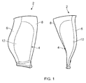
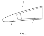
- Figures 1 and 2 show a composite fan blade 2 for a jet engine (not shown).
- the fan blade 2 comprises a composite aerofoil body 4 and protective leading and trailing metal edges 6, 8 which are adhesively bonded to the leading and trailing edges of the composite aerofoil body 4.
- the trailing metal edge 8 further extends around the tip of the composite aerofoil body 4 and is adhesively bonded to it.
- the leading metal edge 6 may extend around the tip of the composite aerofoil body 4 instead.
- a separate metal tip edge could be provided that is adhesively bonded to the composite body 4.
- the composite aerofoil body 4 is made from a composite material, for example, a glass or carbon fibre reinforced polymer (GFRP, CFRP).
- the metal leading and trailing edges 6, 8 are made from titanium. It should be appreciated that the metal edges could be made from other suitable metals such as steel.
- the outer surfaces of the composite aerofoil body 4 are provided with an adhesive layer that is co-cured with the composite body 4.
- the pressure surface is further provided with an additional elastic polyurethane layer on top of the adhesive layer. Both surfaces are coated with a polyurethane paint layer which provides a smooth aerodynamic finish, and improves the aesthetic appearance.
- the leading metal edge 6 and the trailing metal edge 8 may become damaged from either impacts, causing chips/notches, or erosion, causing a change in the profile of the edge.
- the repair process 48 is initiated by an inspection process 50 in which the leading metal edge 6 and the trailing metal edge 8 are inspected for impact damage or erosion damage. If, upon inspection, damaged is found, a 3D scan 52 is performed in which the 3D geometry of the surface of the damaged metal edge 6, 8 is mapped. This produces 3D data that is used to create a CAD/CAM program 54 for the repair process.
- the metal edge 6, 8 is then machined 56 in the region to be repaired, which may be a localized repair region or may be the entire length of the metal edge 6, 8 if the edge needs to be re-profiled.
- the machining process 56 is performed in order to provide a suitable surface geometry for a subsequent metal deposition process.
- a cleaning and etching process 58 is then performed which removes impurities such as oxides from the repair region.
- a metal deposition process 60 is then carried out on the repair region to add metal to the repair region so as to restore the metal edge 6, 8 to its original profile.
- the metal deposition process 60 is a blown powder direct laser deposition process, in which a plurality of layers of metal are deposited on top of one another to build-up metal in the repair region.
- the metal deposition process 60 is used to fill-in notches/chips or to re-profile the metal edge 6, 8, thus restoring the metal edge 6, 8 to its original profile.
- the metal deposition process 60 uses a laser power in the region of 450W, which causes the temperature of the metal edge 6, 8 to be increased.
- a heatsink 14 is thermally coupled to the metal edge 6, 8 during the metal deposition process 60.
- the heatsink 14 also acts to prevent the temperature of the composite body itself reaching unacceptably high levels (which may be 80°C). Temperatures beyond these levels may cause the adhesive and/or composite material to degrade.
- the heatsink 14 will be described in detail below with reference to Figures 4 and 5 .
- the repair region i.e. the metal deposited in the repair region
- a heat treatment process 62 in which the temperature of the repair region (i.e. the region in which the metal has been deposited) is raised to approximately 600°C for one hour.
- the heat treatment process 62 alleviates tensile stress within the deposited metal and the surrounding area. This improves impact resistance and prevents the interface between the original metal and the deposited metal from cracking. Due to the high temperatures involved, the heatsink 14 remains thermally coupled to the metal edge 6, 8 so as to avoid the adhesive and the composite material from being overheated.
- the heat treatment process 62 is followed by an etching process 64 which removes impurities from the surface of the deposited material, and there then follows a polishing process 68 which produces a smooth surface.
- the metal deposited in the repair region is then peened 70, which reduces the likelihood of crack propagation. In some embodiments, the peening process 70 may not be required.
- the metal edge 6, 8 that has been repaired is then inspected to ensure that the repair has been carried out successfully.
- FIG 4 shows a perspective view of a heatsink 14 which can be used in the repair process described above in order to assist in the dissipation or transfer of thermal energy (i.e. heat) from the metal edge 6, 8 being repaired.
- the use of the heatsink 14 prevents the temperature of the adhesive bonding the metal edge 6, 8 to the composite body 4 from reaching levels at which the adhesive bond would be compromised. Further, the use of the heatsink 14 prevents the temperature of the composite material of the composite body from reaching levels at which the composite material itself would be compromised.
- the heatsink 14 is a liquid-cooled heatsink and therefore during use a liquid is used to transfer thermal energy (i.e. heat) received by the heatsink away from the heatsink 14 (and therefore away from the metal edge 6, 8).
- the heatsink 14 is manufactured from a thermally conductive metal such as copper and has a base 16 comprising a recess in the form of an elongate channel 26. As will be described in detail below, the inner profile of the channel 26 substantially corresponds to the outer profile of the metal edge 6, 8.
- the heatsink 14 also comprises an opening 28 that extends through the heatsink 14 from an upper surface 30 and which opens into the channel 26.
- the heatsink 14 is provided with two fluid passageways, each having an inlet 22 and an outlet (not shown). The fluid passageways are located on either side of the opening 28 and extend through the heatsink 14 in the same general direction as the direction of extent of the channel 26.
- the heatsink 14 is located over the metal edge 6, 8 such that the region to be repaired or restored is accessible through the opening 28. With the heatsink 14 located over the metal edge 6, 8, the base 16 is in physical contact with the metal edge 6, 8 and is therefore thermally coupled to it.
- the inlet ports 22 are connected to respective inlet tubes 34 which are connected together with a fluid coupling 38.
- the fluid coupling 38 is connected to a fluid pump (not shown) for pumping cooling fluid, such as water, through the heatsink 14.
- the outlet ports are connected to respective outlet tubes 40 which are connected together with a fluid coupling 42.
- the fluid coupling 42 is connected to a heat exchanger (not shown) which is arranged to extract heat from the cooling fluid so as to cool it.
- the pump may be connected to the heat exchanger so as to form a closed system.
- the pump is operated to pump cooling liquid, such as water, through the fluid passageways in the heatsink 14.
- the metal deposition process 60 is performed through the access opening 28, specifically, metal powder is deposited through the opening 28 and the laser is directed through the opening 28.
- Heat generated by the metal deposition process 60 is transferred away from the metal edge 6, 8 to the heatsink 14 and the flow of cooling liquid acts to transfer the heat away from the heatsink 14 to the cooling liquid.
- This forced cooling effect efficiently cools the metal edge 6, 8, preventing overheating of the adhesive and the composite material itself. This allows a metal deposition process 60 to be performed on a region of the fan blade which is sensitive to excessive temperatures.
- the pump is also operated to pump cooling liquid through the heatsink 14, thereby efficiently transferring thermal energy away from the metal edge 6, 8.
- this forced cooling prevents overheating of the adhesive and the composite material itself.
- the cooling liquid has been described as being water, any other suitable liquid could be used.
- the cooling liquid may be conveyed through the heatsink 14 using any suitable means, for example under the force of gravity.
- the heatsink 14 can be repositioned along the metal edge 6, 8 such that the second repair region is accessible through the opening 28. The repair process 48 is then repeated on this second repair region.
- metal deposition process 60 is blown powder direct laser deposition. It should be appreciated that any suitable metal deposition (i.e. metal additive) process could be used.
- leading/and or trailing metal edge 6, 8 of a fan blade 2 is repaired. It will be appreciated that the metal tip of the fan blade may also be repaired using the same method.
- the metal tip of the fan blade may either be formed by the leading/and or trailing metal edge 6, 8 of a fan blade 2 or a separate component may be provided.
- the heatsink has been described as a liquid-cooled heatsink that is cooled with a cooling liquid such as water.
- a cooling liquid such as water
- the heatsink could be cooled by an airflow, either forced or driven by convection.
- the repair method is for repairing the metal leading or trailing edge 6, 8 of a fan blade 2 for a jet engine.
- the method could be used to repair any metal component adhesively bonded to a composite body.
- it could be used to repair a metal edge bonded to a composite wing component.
- the method could be used to repair non-aircraft components, such as a metal part bonded to a composite body component of a car.
Landscapes
- Engineering & Computer Science (AREA)
- Mechanical Engineering (AREA)
- General Engineering & Computer Science (AREA)
- Chemical & Material Sciences (AREA)
- Physics & Mathematics (AREA)
- Materials Engineering (AREA)
- Optics & Photonics (AREA)
- Composite Materials (AREA)
- Plasma & Fusion (AREA)
- Chemical Kinetics & Catalysis (AREA)
- Metallurgy (AREA)
- Organic Chemistry (AREA)
- Thermal Sciences (AREA)
- Pressure Welding/Diffusion-Bonding (AREA)
- Structures Of Non-Positive Displacement Pumps (AREA)
Abstract
There is disclosed a method of repairing a component 2 having a metal part 6, 8 adhesively bonded to a composite body 4. The method comprises thermally coupling a heatsink 14 to the metal part 6, 8 adjacent to a repair region of the metal part 6, 8 which is to be repaired; and performing a metal deposition process 60 on the metal part 6, 8 in the repair region. During the metal deposition process 60 the heatsink 14 acts to transfer thermal energy away from the metal part caused by the metal deposition process 60. There is also disclosed equipment for repairing a component 2 having a metal part 6, 8 adhesively bonded to a composite body 4.
Description
- The disclosure relates to a method and equipment for repairing a component having a metal part adhesively bonded to a composite body. In particular, although not exclusively, the disclosure relates to a method and equipment for repairing a fan blade having a leading and/or trailing metal edge adhesively bonded to a composite body.
- Composite fan blades are known which comprise a composite aerofoil body and leading and trailing protective metal edges adhesively bonded to the composite aerofoil body. The composite aerofoil body is typically made from a composite material such as a glass or carbon fibre reinforced polymer (GFRP, CFRP), whilst the leading and trailing protective metal edges are typically made from titanium or steel. The leading and trailing metal edges are provided to protect the edge of the composite aerofoil body from impact damage and erosion. During use, impacts such as from bird strikes and runway debris may damage the metal edges, and over time small particulate matter may erode the metal edges, thereby changing their profile.
- It is desirable to repair the leading/trailing metal edges of composite fan blades in order to extend their life. Impact damage to the metal edges, such as chips or notches, can be repaired by "dressing-out" the damaged area. This involves removing material to create a smoother profile in order reduce stress concentration areas. The metal edges can be re-profiled by using a material removal process such as abrading. Whilst these methods of repair may increase the life of the fan blade, they involve the removal of metal and so there may no longer be sufficient metal remaining after a number of repairs.
- It is therefore desirable to provide an improved method and equipment for repairing a component having a metal part adhesively bonded to a composite body.
- According to an aspect there is provided a method of repairing a component having a metal part attached (for example adhesively bonded) to a composite body, the method comprising: thermally coupling a heatsink to the metal part adjacent to a repair region of the metal part which is to be repaired; and performing a metal deposition process on the metal part in the repair region; wherein during the metal deposition process the heatsink acts to transfer (or dissipate) thermal energy away from the metal part caused by the metal deposition process. The use of a heatsink to transfer heat away from the metal part means that during the metal deposition process the adhesive bond and/or the resin of the composite body do not reach excessive temperatures. This allows the metal part to be repaired using a material addition process.
- It should be appreciated that the order that the method steps are presented in is not limiting and the steps could be carried out in any particular order.
- The heatsink may have a heatsink base having a profile corresponding to that of the metal part, and thermally coupling the heatsink to the metal part may include placing the heatsink base against the metal part. The heatsink base may comprise a recess for receiving the metal part. The recess may be in the form of a channel. The channel may have a profile corresponding to the edge of a fan blade, such as a leading edge or a trailing edge. The heatsink may be a liquid-cooled heatsink, such as a water-cooled heatsink. During the metal deposition process a cooling liquid, such as water, may be used to transfer (or dissipate) thermal energy away from the heatsink. This may increase the transfer rate of heat away from the metal part. During the metal deposition process a cooling liquid, such as water, may be pumped past the heatsink. A cooling liquid may be pumped through, over, or across the heatsink. In other embodiments other ways of causing a cooling liquid, such as water, to flow past the heatsink may be used.
- The heatsink may define an opening, and with the heatsink thermally coupled to the metal part, at least a part of a repair region may be exposed through the opening. The heatsink may be thermally coupled to the metal part such that it surrounds at least a part of a repair region. The metal deposition process may be performed through the opening.
- The heatsink may have one or more formations or features for promoting heat transfer (or dissipation), such as heat transfer fins.
- The method may further comprise, after the metal deposition process, performing a heat treatment process on the repair region, wherein during the heat treatment process the heatsink acts to transfer (or dissipate) thermal energy away from the metal part caused by the heat treatment process. During the heat treatment process, a cooling liquid, such as water, may be used to transfer (or dissipate) thermal energy away from the heatsink. A cooling liquid, such as water, may be pumped past the heatsink during the heat treatment process. A cooling liquid may be pumped through, over, or across the heatsink. In other embodiments other ways of causing a cooling liquid, such as water, to flow past the heatsink may be used. The heat treatment process may be performed through the opening.
- The component may be a blade or a vane. The metal part may be a metal leading or trailing edge or tip.
- According to another aspect there is provided equipment for repairing a component having a metal part adhesively bonded to a composite body, the equipment comprising: a heatsink arranged to be thermally coupled to the metal part adjacent to a repair region of the metal part which is to be repaired; and metal deposition apparatus for performing a metal deposition process on the metal part in the repair region.
- The heatsink may have a heatsink base having a profile corresponding to that of the metal part. The heatsink base may comprise a recess for receiving the metal part. The recess may be in the form of a channel. The heatsink may be a liquid-cooled heatsink.
- The heatsink may define an opening which is arranged such that with the heatsink thermally coupled to the metal part, at least a part of a repair region is exposed through the opening.
- The equipment may further comprise heat treatment apparatus for performing a heat treatment process on the repair region.
- The disclosure also relates to a heatsink for use in the method according to any statement herein, or according to the equipment of any statement herein.
- The disclosure may comprise any combination of the features and/or limitations referred to herein, except combinations of such features that are mutually exclusive.
- Embodiments will now be described, by way of example, with reference to the accompanying drawings, in which:
-
Figure 1 schematically shows perspective views of a composite fan blade for a gas turbine engine, such as a jet engine; -
Figure 2 schematically shows a cross-sectional view of the composite fan blade ofFigure 1 ; -
Figure 3 schematically shows a repair process in accordance with an embodiment of the invention; -
Figure 4 schematically shows a perspective view of a heatsink according to an embodiment; and -
Figure 5 schematically shows a perspective view of the heatsink ofFigure 4 thermally coupled to the metal edge of the fan blade ofFigure 1 . -
Figures 1 and2 show acomposite fan blade 2 for a jet engine (not shown). Thefan blade 2 comprises acomposite aerofoil body 4 and protective leading and trailingmetal edges composite aerofoil body 4. Thetrailing metal edge 8 further extends around the tip of thecomposite aerofoil body 4 and is adhesively bonded to it. In other embodiments, the leadingmetal edge 6 may extend around the tip of thecomposite aerofoil body 4 instead. In yet a further embodiment a separate metal tip edge could be provided that is adhesively bonded to thecomposite body 4. Thecomposite aerofoil body 4 is made from a composite material, for example, a glass or carbon fibre reinforced polymer (GFRP, CFRP). The metal leading andtrailing edges composite aerofoil body 4 are provided with an adhesive layer that is co-cured with thecomposite body 4. The pressure surface is further provided with an additional elastic polyurethane layer on top of the adhesive layer. Both surfaces are coated with a polyurethane paint layer which provides a smooth aerodynamic finish, and improves the aesthetic appearance. In use, the leadingmetal edge 6 and thetrailing metal edge 8 may become damaged from either impacts, causing chips/notches, or erosion, causing a change in the profile of the edge. - A method of repairing the leading/trailing
metal edges composite fan blade 2 using a metal deposition process will now be described with reference toFigure 3 . - The
repair process 48 is initiated by aninspection process 50 in which the leadingmetal edge 6 and the trailingmetal edge 8 are inspected for impact damage or erosion damage. If, upon inspection, damaged is found, a3D scan 52 is performed in which the 3D geometry of the surface of the damagedmetal edge CAM program 54 for the repair process. Themetal edge metal edge machining process 56 is performed in order to provide a suitable surface geometry for a subsequent metal deposition process. A cleaning andetching process 58 is then performed which removes impurities such as oxides from the repair region. Ametal deposition process 60 is then carried out on the repair region to add metal to the repair region so as to restore themetal edge - In this embodiment the
metal deposition process 60 is a blown powder direct laser deposition process, in which a plurality of layers of metal are deposited on top of one another to build-up metal in the repair region. In this embodiment, themetal deposition process 60 is used to fill-in notches/chips or to re-profile themetal edge metal edge metal deposition process 60 uses a laser power in the region of 450W, which causes the temperature of themetal edge metal edges composite body 4 reaching unacceptably high levels (which may be 120°C), aheatsink 14 is thermally coupled to themetal edge metal deposition process 60. Theheatsink 14 also acts to prevent the temperature of the composite body itself reaching unacceptably high levels (which may be 80°C). Temperatures beyond these levels may cause the adhesive and/or composite material to degrade. Theheatsink 14 will be described in detail below with reference toFigures 4 and5 . - Following the
metal deposition process 60, the repair region (i.e. the metal deposited in the repair region) is subjected to aheat treatment process 62 in which the temperature of the repair region (i.e. the region in which the metal has been deposited) is raised to approximately 600°C for one hour. Theheat treatment process 62 alleviates tensile stress within the deposited metal and the surrounding area. This improves impact resistance and prevents the interface between the original metal and the deposited metal from cracking. Due to the high temperatures involved, theheatsink 14 remains thermally coupled to themetal edge heat treatment process 62 is followed by anetching process 64 which removes impurities from the surface of the deposited material, and there then follows apolishing process 68 which produces a smooth surface. The metal deposited in the repair region is then peened 70, which reduces the likelihood of crack propagation. In some embodiments, thepeening process 70 may not be required. Themetal edge -
Figure 4 shows a perspective view of aheatsink 14 which can be used in the repair process described above in order to assist in the dissipation or transfer of thermal energy (i.e. heat) from themetal edge heatsink 14 prevents the temperature of the adhesive bonding themetal edge composite body 4 from reaching levels at which the adhesive bond would be compromised. Further, the use of theheatsink 14 prevents the temperature of the composite material of the composite body from reaching levels at which the composite material itself would be compromised. In this embodiment theheatsink 14 is a liquid-cooled heatsink and therefore during use a liquid is used to transfer thermal energy (i.e. heat) received by the heatsink away from the heatsink 14 (and therefore away from themetal edge 6, 8). Theheatsink 14 is manufactured from a thermally conductive metal such as copper and has a base 16 comprising a recess in the form of anelongate channel 26. As will be described in detail below, the inner profile of thechannel 26 substantially corresponds to the outer profile of themetal edge heatsink 14 also comprises anopening 28 that extends through theheatsink 14 from anupper surface 30 and which opens into thechannel 26. Theheatsink 14 is provided with two fluid passageways, each having aninlet 22 and an outlet (not shown). The fluid passageways are located on either side of theopening 28 and extend through theheatsink 14 in the same general direction as the direction of extent of thechannel 26. - As shown in
Figure 5 , in use, prior to themetal deposition process 60, theheatsink 14 is located over themetal edge opening 28. With theheatsink 14 located over themetal edge base 16 is in physical contact with themetal edge inlet ports 22 are connected torespective inlet tubes 34 which are connected together with afluid coupling 38. Thefluid coupling 38 is connected to a fluid pump (not shown) for pumping cooling fluid, such as water, through theheatsink 14. The outlet ports are connected torespective outlet tubes 40 which are connected together with afluid coupling 42. Thefluid coupling 42 is connected to a heat exchanger (not shown) which is arranged to extract heat from the cooling fluid so as to cool it. The pump may be connected to the heat exchanger so as to form a closed system. - During the
metal deposition process 60 the pump is operated to pump cooling liquid, such as water, through the fluid passageways in theheatsink 14. Themetal deposition process 60 is performed through the access opening 28, specifically, metal powder is deposited through theopening 28 and the laser is directed through theopening 28. Heat generated by themetal deposition process 60 is transferred away from themetal edge heatsink 14 and the flow of cooling liquid acts to transfer the heat away from theheatsink 14 to the cooling liquid. This forced cooling effect efficiently cools themetal edge metal deposition process 60 to be performed on a region of the fan blade which is sensitive to excessive temperatures. During theheat treatment process 62 the pump is also operated to pump cooling liquid through theheatsink 14, thereby efficiently transferring thermal energy away from themetal edge metal deposition process 60, this forced cooling prevents overheating of the adhesive and the composite material itself. Although the cooling liquid has been described as being water, any other suitable liquid could be used. Further, although it has been described that the cooling liquid is pumped through theheatsink 14, it may be conveyed through theheatsink 14 using any suitable means, for example under the force of gravity. - Once the
repair process 48 has been completed, if there is a second region that requires repair, theheatsink 14 can be repositioned along themetal edge opening 28. Therepair process 48 is then repeated on this second repair region. - In the foregoing description it has been described that the
metal deposition process 60 is blown powder direct laser deposition. It should be appreciated that any suitable metal deposition (i.e. metal additive) process could be used. - In the foregoing description it has been described that the leading/and or trailing
metal edge fan blade 2 is repaired. It will be appreciated that the metal tip of the fan blade may also be repaired using the same method. The metal tip of the fan blade may either be formed by the leading/and or trailingmetal edge fan blade 2 or a separate component may be provided. - In the embodiment described the heatsink has been described as a liquid-cooled heatsink that is cooled with a cooling liquid such as water. However, in other embodiments the heatsink could be cooled by an airflow, either forced or driven by convection.
- It has been described that the repair method is for repairing the metal leading or trailing
edge fan blade 2 for a jet engine. However, the method could be used to repair any metal component adhesively bonded to a composite body. For example, it could be used to repair a metal edge bonded to a composite wing component. Further, the method could be used to repair non-aircraft components, such as a metal part bonded to a composite body component of a car.
Claims (15)
- A method of repairing a component having a metal part attached to a composite body, the method comprising:thermally coupling a heatsink to the metal part adjacent to a repair region of the metal part which is to be repaired; andperforming a metal deposition process on the metal part in the repair region;wherein during the metal deposition process the heatsink acts to transfer thermal energy away from the metal part caused by the metal deposition process.
- A method according to claim 1, wherein the heatsink has a heatsink base having a profile corresponding to that of the metal part, wherein thermally coupling the heatsink to the metal part includes placing the heatsink base against the metal part.
- A method according to claim 2, wherein the heatsink base comprises a recess for receiving the metal part.
- A method according to claim 3, wherein the recess is in the form of a channel.
- A method according to any preceding claim, wherein the heatsink is a liquid-cooled heatsink.
- A method according to claim 5, wherein:during the metal deposition process a cooling liquid is used to transfer thermal energy away from the heatsink; and/orduring the metal deposition process a cooling liquid is pumped past the heatsink.
- A method according to any preceding claim, wherein the heatsink defines an opening, and wherein with the heatsink thermally coupled to the metal part, at least a part of the repair region is exposed through the opening.
- A method according to claim 7, wherein:the heatsink is thermally coupled to the metal part such that it surrounds at least a part of the repair region; and/orthe metal deposition process is performed through the opening.
- A method according to any preceding claim, further comprising performing a heat treatment process on the repair region after the metal deposition process, wherein during the heat treatment process the heatsink acts to transfer thermal energy away from the metal part caused by the heat treatment process.
- A method according to claim 9 when appended to claim 5, wherein:during the heat treatment process a cooling liquid is used to transfer thermal energy from the heatsink; and/orduring the heat treatment process a cooling liquid is pumped past the heatsink.
- A method according to claim 9 or claim 10 when appended to claim 7, wherein the heat treatment process is performed through the opening.
- A method according to any preceding claim, wherein the component is a blade or vane, and wherein the metal part is a metal leading edge, trailing edge or tip.
- Equipment for repairing a component having a metal part adhesively bonded to a composite body, the equipment comprising:a heatsink arranged to be thermally coupled to the metal part adjacent to a repair region of the metal part which is to be repaired; andmetal deposition apparatus for performing a metal deposition process on the metal part in the repair region.
- Equipment according to claim 13, further comprising heat treatment apparatus for performing a heat treatment process on the repair region.
- A heatsink for use in the method of any of claims 1-12 or the equipment of claim 13 or claim 14.
Applications Claiming Priority (1)
| Application Number | Priority Date | Filing Date | Title |
|---|---|---|---|
| GBGB1500636.4A GB201500636D0 (en) | 2015-01-15 | 2015-01-15 | Method and equipment for repairing a component |
Publications (1)
| Publication Number | Publication Date |
|---|---|
| EP3045260A1 true EP3045260A1 (en) | 2016-07-20 |
Family
ID=52630611
Family Applications (1)
| Application Number | Title | Priority Date | Filing Date |
|---|---|---|---|
| EP15200327.3A Withdrawn EP3045260A1 (en) | 2015-01-15 | 2015-12-16 | Method and equipment for repairing a component |
Country Status (4)
| Country | Link |
|---|---|
| US (1) | US20160209131A1 (en) |
| EP (1) | EP3045260A1 (en) |
| GB (2) | GB201500636D0 (en) |
| SG (1) | SG10201510569XA (en) |
Cited By (2)
| Publication number | Priority date | Publication date | Assignee | Title |
|---|---|---|---|---|
| WO2019224496A1 (en) * | 2018-05-24 | 2019-11-28 | Safran Aircraft Engines | Fabric comprising aramid fibres for protecting a blade against impacts |
| WO2020169938A1 (en) | 2019-02-21 | 2020-08-27 | Safran Aircraft Engines | Method for repairing a turbomachine rotor blade |
Families Citing this family (1)
| Publication number | Priority date | Publication date | Assignee | Title |
|---|---|---|---|---|
| FR3101562B1 (en) * | 2019-10-08 | 2021-09-10 | Safran Aircraft Engines | Process for stripping at least one area of a turbine engine blade |
Citations (4)
| Publication number | Priority date | Publication date | Assignee | Title |
|---|---|---|---|---|
| EP0433972A1 (en) * | 1989-12-22 | 1991-06-26 | Refurbished Turbine Components Limited | Turbine blade repair |
| EP2327812A1 (en) * | 2009-11-30 | 2011-06-01 | General Electric Company | Near net shape composite airfoil leading edge protective strips made using cold spray deposition |
| DE102010006384A1 (en) * | 2010-01-29 | 2011-08-04 | Lufthansa Technik AG, 22335 | Repair method for a composite component for an aircraft, composite component for an aircraft and apparatus for repairing a composite component for an aircraft |
| EP2631323A1 (en) * | 2012-02-22 | 2013-08-28 | Sikorsky Aircraft Corporation | Erosion and fatigue resistant blade and blade coating |
Family Cites Families (4)
| Publication number | Priority date | Publication date | Assignee | Title |
|---|---|---|---|---|
| US9527169B2 (en) * | 2007-02-27 | 2016-12-27 | Siemens Energy, Inc. | Process and apparatus for cooling a metal part during a welding operation |
| EP2754855A1 (en) * | 2013-01-14 | 2014-07-16 | Siemens Aktiengesellschaft | Device for clamping a turbine blade |
| US9395126B2 (en) * | 2013-03-13 | 2016-07-19 | Siemens Energy, Inc. | Method and apparatus for cooling superalloy turbine components during component welding |
| US9476304B2 (en) * | 2013-05-10 | 2016-10-25 | Caterpillar Inc. | Laser casting blade repair |
-
2015
- 2015-01-15 GB GBGB1500636.4A patent/GB201500636D0/en not_active Ceased
- 2015-12-16 EP EP15200327.3A patent/EP3045260A1/en not_active Withdrawn
- 2015-12-16 US US14/971,292 patent/US20160209131A1/en not_active Abandoned
- 2015-12-16 GB GB1522167.4A patent/GB2534285A/en not_active Withdrawn
- 2015-12-22 SG SG10201510569XA patent/SG10201510569XA/en unknown
Patent Citations (4)
| Publication number | Priority date | Publication date | Assignee | Title |
|---|---|---|---|---|
| EP0433972A1 (en) * | 1989-12-22 | 1991-06-26 | Refurbished Turbine Components Limited | Turbine blade repair |
| EP2327812A1 (en) * | 2009-11-30 | 2011-06-01 | General Electric Company | Near net shape composite airfoil leading edge protective strips made using cold spray deposition |
| DE102010006384A1 (en) * | 2010-01-29 | 2011-08-04 | Lufthansa Technik AG, 22335 | Repair method for a composite component for an aircraft, composite component for an aircraft and apparatus for repairing a composite component for an aircraft |
| EP2631323A1 (en) * | 2012-02-22 | 2013-08-28 | Sikorsky Aircraft Corporation | Erosion and fatigue resistant blade and blade coating |
Cited By (8)
| Publication number | Priority date | Publication date | Assignee | Title |
|---|---|---|---|---|
| WO2019224496A1 (en) * | 2018-05-24 | 2019-11-28 | Safran Aircraft Engines | Fabric comprising aramid fibres for protecting a blade against impacts |
| FR3081496A1 (en) * | 2018-05-24 | 2019-11-29 | Safran Aircraft Engines | FABRIC COMPRISING ARAMID FIBERS FOR PROTECTING A DAWN FROM IMPACTS |
| US11371357B2 (en) | 2018-05-24 | 2022-06-28 | Safran Aircraft Engines | Fabric comprising aramid fibres for protecting a blade against impacts |
| WO2020169938A1 (en) | 2019-02-21 | 2020-08-27 | Safran Aircraft Engines | Method for repairing a turbomachine rotor blade |
| FR3093017A1 (en) * | 2019-02-21 | 2020-08-28 | Safran Aircraft Engines | PROCESS FOR REPAIRING A TURBOMACHINE PROPELLER BLADE |
| CN113498450A (en) * | 2019-02-21 | 2021-10-12 | 赛峰飞机发动机公司 | Method for repairing a turbine rotor blade |
| CN113498450B (en) * | 2019-02-21 | 2023-07-28 | 赛峰飞机发动机公司 | Method for repairing a turbine propeller blade |
| US12044141B2 (en) | 2019-02-21 | 2024-07-23 | Safran Aircraft Engines | Method for repairing a turbomachine rotor blade |
Also Published As
| Publication number | Publication date |
|---|---|
| GB201522167D0 (en) | 2016-01-27 |
| GB201500636D0 (en) | 2015-03-04 |
| GB2534285A (en) | 2016-07-20 |
| US20160209131A1 (en) | 2016-07-21 |
| SG10201510569XA (en) | 2016-08-30 |
Similar Documents
| Publication | Publication Date | Title |
|---|---|---|
| EP1662092B1 (en) | Fatigue-resistant gas turbine airfoil and method therefor | |
| US8969760B2 (en) | System and method for manufacturing an airfoil | |
| EP3059040A1 (en) | Component repair using confined laser drilling | |
| EP4086429A1 (en) | Turbine blade repair method using additive manufacturing | |
| EP1880793A2 (en) | High pressure single turbine blade tip repair with laser cladding | |
| EP1944120A2 (en) | Weld repair of metallic components | |
| EP3045260A1 (en) | Method and equipment for repairing a component | |
| CN101970170B (en) | Method for manufacturing hollow blade | |
| US20070157447A1 (en) | Method of improving the properties of a repaired component and a component improved thereby | |
| US20190284942A1 (en) | Method of repairing ceramic coating, ceramic coating, turbine member, and gas turbine | |
| US9127550B2 (en) | Turbine superalloy component defect repair with low-temperature curing resin | |
| CN113498450B (en) | Method for repairing a turbine propeller blade | |
| CN105904104A (en) | Component repair using confined laser drilling | |
| BR112013027907B1 (en) | CLEANING AND STRIPPING PROCESS OF A TURBOMOTOR BLADE WITH THE AID OF A PULSED LASER | |
| CN106521487A (en) | Remanufacturing method for blade of titanium alloy gas compressor in middle service period | |
| KR20180019233A (en) | How to repair turbine blades | |
| CN110819981A (en) | Method for repairing nickel-based single crystal turbine blade shroud | |
| CN104755638A (en) | Local heat treatment and thermal management systems for engine components | |
| EP1807237A2 (en) | Weld shielding device for automated welding of impellers and blisks | |
| CN106119832A (en) | The restorative procedure of electromotor booster pump impeller blade tip cavitation erosion | |
| EP2946870A1 (en) | A boroscope and a method of processing a component within an assembled apparatus using a boroscope | |
| EP1739195A1 (en) | Countering laser shock peening induced blade twist | |
| EP3282034A1 (en) | Aluminum fan blade tip prepared for thermal spray deposition of abrasive by laser ablation | |
| CN107740120A (en) | The restorative procedure of engine reinforcing impeller of pump blade tip cavitation erosion | |
| EP3315744B1 (en) | Turbine blade maintenance method |
Legal Events
| Date | Code | Title | Description |
|---|---|---|---|
| PUAI | Public reference made under article 153(3) epc to a published international application that has entered the european phase |
Free format text: ORIGINAL CODE: 0009012 |
|
| AK | Designated contracting states |
Kind code of ref document: A1 Designated state(s): AL AT BE BG CH CY CZ DE DK EE ES FI FR GB GR HR HU IE IS IT LI LT LU LV MC MK MT NL NO PL PT RO RS SE SI SK SM TR |
|
| AX | Request for extension of the european patent |
Extension state: BA ME |
|
| STAA | Information on the status of an ep patent application or granted ep patent |
Free format text: STATUS: THE APPLICATION HAS BEEN PUBLISHED |
|
| STAA | Information on the status of an ep patent application or granted ep patent |
Free format text: STATUS: THE APPLICATION IS DEEMED TO BE WITHDRAWN |
|
| 18D | Application deemed to be withdrawn |
Effective date: 20170121 |