EP3045119B1 - Reusable biopsy gun and a lockable biopsy needle for use therewith - Google Patents
Reusable biopsy gun and a lockable biopsy needle for use therewith Download PDFInfo
- Publication number
- EP3045119B1 EP3045119B1 EP16153732.9A EP16153732A EP3045119B1 EP 3045119 B1 EP3045119 B1 EP 3045119B1 EP 16153732 A EP16153732 A EP 16153732A EP 3045119 B1 EP3045119 B1 EP 3045119B1
- Authority
- EP
- European Patent Office
- Prior art keywords
- cannula
- stylet
- biopsy
- longitudinal axis
- biopsy needle
- Prior art date
- Legal status (The legal status is an assumption and is not a legal conclusion. Google has not performed a legal analysis and makes no representation as to the accuracy of the status listed.)
- Active
Links
- 238000001574 biopsy Methods 0.000 title claims description 232
- 230000008878 coupling Effects 0.000 claims description 116
- 238000010168 coupling process Methods 0.000 claims description 116
- 238000005859 coupling reaction Methods 0.000 claims description 116
- 238000010304 firing Methods 0.000 claims description 7
- 230000004913 activation Effects 0.000 claims description 6
- 210000001519 tissue Anatomy 0.000 description 15
- 238000000034 method Methods 0.000 description 5
- 230000008901 benefit Effects 0.000 description 3
- 238000004140 cleaning Methods 0.000 description 2
- 238000004891 communication Methods 0.000 description 2
- 230000004888 barrier function Effects 0.000 description 1
- 239000008280 blood Substances 0.000 description 1
- 210000004369 blood Anatomy 0.000 description 1
- 210000001124 body fluid Anatomy 0.000 description 1
- 239000010839 body fluid Substances 0.000 description 1
- 230000008859 change Effects 0.000 description 1
- 238000006073 displacement reaction Methods 0.000 description 1
- 238000001746 injection moulding Methods 0.000 description 1
- 239000007788 liquid Substances 0.000 description 1
- 238000004519 manufacturing process Methods 0.000 description 1
- 239000000463 material Substances 0.000 description 1
- 230000008569 process Effects 0.000 description 1
- 210000002307 prostate Anatomy 0.000 description 1
- 230000001681 protective effect Effects 0.000 description 1
- 230000000717 retained effect Effects 0.000 description 1
- 238000005070 sampling Methods 0.000 description 1
- 210000004872 soft tissue Anatomy 0.000 description 1
- 230000001954 sterilising effect Effects 0.000 description 1
Images


Classifications
-
- A—HUMAN NECESSITIES
- A61—MEDICAL OR VETERINARY SCIENCE; HYGIENE
- A61B—DIAGNOSIS; SURGERY; IDENTIFICATION
- A61B10/00—Other methods or instruments for diagnosis, e.g. instruments for taking a cell sample, for biopsy, for vaccination diagnosis; Sex determination; Ovulation-period determination; Throat striking implements
- A61B10/02—Instruments for taking cell samples or for biopsy
- A61B10/0233—Pointed or sharp biopsy instruments
- A61B10/0266—Pointed or sharp biopsy instruments means for severing sample
- A61B10/0275—Pointed or sharp biopsy instruments means for severing sample with sample notch, e.g. on the side of inner stylet
-
- A—HUMAN NECESSITIES
- A61—MEDICAL OR VETERINARY SCIENCE; HYGIENE
- A61B—DIAGNOSIS; SURGERY; IDENTIFICATION
- A61B10/00—Other methods or instruments for diagnosis, e.g. instruments for taking a cell sample, for biopsy, for vaccination diagnosis; Sex determination; Ovulation-period determination; Throat striking implements
- A61B10/02—Instruments for taking cell samples or for biopsy
- A61B2010/0208—Biopsy devices with actuators, e.g. with triggered spring mechanisms
-
- A—HUMAN NECESSITIES
- A61—MEDICAL OR VETERINARY SCIENCE; HYGIENE
- A61B—DIAGNOSIS; SURGERY; IDENTIFICATION
- A61B17/00—Surgical instruments, devices or methods, e.g. tourniquets
- A61B2017/0046—Surgical instruments, devices or methods, e.g. tourniquets with a releasable handle; with handle and operating part separable
- A61B2017/00473—Distal part, e.g. tip or head
-
- A—HUMAN NECESSITIES
- A61—MEDICAL OR VETERINARY SCIENCE; HYGIENE
- A61B—DIAGNOSIS; SURGERY; IDENTIFICATION
- A61B90/00—Instruments, implements or accessories specially adapted for surgery or diagnosis and not covered by any of the groups A61B1/00 - A61B50/00, e.g. for luxation treatment or for protecting wound edges
- A61B90/03—Automatic limiting or abutting means, e.g. for safety
- A61B2090/033—Abutting means, stops, e.g. abutting on tissue or skin
- A61B2090/034—Abutting means, stops, e.g. abutting on tissue or skin abutting on parts of the device itself
-
- A—HUMAN NECESSITIES
- A61—MEDICAL OR VETERINARY SCIENCE; HYGIENE
- A61B—DIAGNOSIS; SURGERY; IDENTIFICATION
- A61B90/00—Instruments, implements or accessories specially adapted for surgery or diagnosis and not covered by any of the groups A61B1/00 - A61B50/00, e.g. for luxation treatment or for protecting wound edges
- A61B90/03—Automatic limiting or abutting means, e.g. for safety
- A61B2090/037—Automatic limiting or abutting means, e.g. for safety with a frangible part, e.g. by reduced diameter
-
- A—HUMAN NECESSITIES
- A61—MEDICAL OR VETERINARY SCIENCE; HYGIENE
- A61B—DIAGNOSIS; SURGERY; IDENTIFICATION
- A61B90/00—Instruments, implements or accessories specially adapted for surgery or diagnosis and not covered by any of the groups A61B1/00 - A61B50/00, e.g. for luxation treatment or for protecting wound edges
- A61B90/08—Accessories or related features not otherwise provided for
- A61B2090/0801—Prevention of accidental cutting or pricking
-
- Y—GENERAL TAGGING OF NEW TECHNOLOGICAL DEVELOPMENTS; GENERAL TAGGING OF CROSS-SECTIONAL TECHNOLOGIES SPANNING OVER SEVERAL SECTIONS OF THE IPC; TECHNICAL SUBJECTS COVERED BY FORMER USPC CROSS-REFERENCE ART COLLECTIONS [XRACs] AND DIGESTS
- Y10—TECHNICAL SUBJECTS COVERED BY FORMER USPC
- Y10T—TECHNICAL SUBJECTS COVERED BY FORMER US CLASSIFICATION
- Y10T29/00—Metal working
- Y10T29/49—Method of mechanical manufacture
- Y10T29/49826—Assembling or joining
- Y10T29/4984—Retaining clearance for motion between assembled parts
Definitions
- the invention relates to a kit comprising a biopsy needle wherein the cannula and stylet may be arranged in a locked position, preventing longitudinal movement relative to each other, and a reusable biopsy gun comprising means for moving the biopsy needle from its locked position to an unlocked position where the cannula and stylet may be moved in the longitudinal direction relative to each other.
- the use of a reusable biopsy gun and a biopsy needle comprises a number of steps.
- the biopsy needle is loaded into the biopsy gun.
- the biopsy gun is armed, this is typically done by compressing two springs, one for the cannula of the biopsy needle and one for the stylet of the biopsy needle.
- the biopsy needle is inserted into the sampling site, e.g. soft tissue for example from the prostate, from which samples are desired.
- the biopsy gun is fired, e.g. when the gun has been armed by springs these are released.
- the stylet is provided with a small recess at the tip into which sample tissue will move.
- the cannula is fired which cuts off the sample tissue and contains it in the recess. The biopsy needle is then pulled out of the body and the sample tissue may be retrieved.
- the present invention relates primarily to the first step.
- Loading of the biopsy needle into the biopsy gun comprises a number of handling issues.
- the nurse or surgeon has to handle two separate elements, one of which is very sharp and thus may involve unintentionally puncturing of the protective barrier, such as gloves, and even the tissue of the person loading the needle into the gun.
- the cannula and stylet are freely slidable relative to each other when loading the biopsy needle into the biopsy gun. This results in a high risk of the person handling the gun being pierced when loading the gun.
- some biopsy needles have been formed with locking members in order to prevent unintentional sliding movement between the cannula and the stylet.
- these comprise a third element which has to be removed before or after loading of the needle.
- such a third element adds to the cost of the biopsy needle.
- WO 2007/014904 discloses an automatic biopsy gun having first and second slides associated with a cannula and a stylet respectively, and comprising means for actuating the first and the second slides from respective forward configurations to respective retracted configurations.
- US5127419 discloses a biopsy instrument having a driving member slideably engaged with a track formed along the length of a housing.
- the driving member comprises proximal and distal slots which are notched at respective distal and proximal ends.
- the biopsy needle is for use in the biopsy gun.
- the biopsy needle will typically be adapted for replaceable arrangement in the biopsy gun and in such configuration the biopsy needle will typically be a single use biopsy needle. However, in some cases the biopsy needle could be separately sterilized or otherwise cleaned in order for multiple uses.
- a stylet coupling part is arranged at the proximal end of the stylet, and a cannula coupling part is arranged at the proximal end of the cannula.
- the coupling parts are typically moulded onto the respective proximal ends, for example by injection moulding.
- the parts can be formed in many sizes and shapes suitable for the specific needs.
- 'proximal' referral is made to an end of a part or element that is closest to user when the needle is inserted into the patient.
- the opposite end of the same part or element is referred to as the 'distal' end.
- the rotatable movement of the stylet and the cannula relative to each other between the locked and the unlocked position can be provided by forming the cannula coupling part with a tubular coupling member having a tubular compartment for at least partly receiving the stylet coupling part, wherein the tubular compartment is formed with a track which engages with a protrusion formed on the stylet coupling part.
- the track thus functions as a limit for the protrusion, thereby controlling the relative movement between the cannula and the stylet.
- the track thus defines the shape of the track, it is possible to limit the pattern and/or extent of movement between the cannula and the stylet.
- the track is made up of at least a first and a second leg, the first leg extending circumferentially around the axis A - A, and the second leg extending longitudinally along the axis A - A.
- the biopsy needle is provided with a coupling arrangement which allows the protrusion to be moved between the first leg and the second leg via plastic deformation of at least one of the stylet coupling part or the cannula coupling part. This provides an added level of security, as additional force must be applied in order to move the biopsy needle between its locked and unlocked position.
- At least one rib is arranged on an outer surface of either the cannula coupling part or the stylet coupling part, and at least one tab is arranged on an outer surface of the other coupling part.
- the rib and tab facilitate the rotational movement between the locked and unlocked position, as these function as gripping means. For example, an operator can easily manipulate the rib and tab relative to each other.
- a biopsy gun can comprise activation means for at least moving the biopsy needle from the locked position to the unlocked position.
- activation means can for example be provided by a protrusion in the housing of the biopsy gun, e.g. in the lid, which engages with either the rib or the tab when the biopsy gun is closed and thereby rotates the cannula and the stylet relative to each other by engagement of the rib or the tab with the protrusion.
- the kit may comprise a number of biopsy needles as described above and the biopsy gun for use with said biopsy needles.
- the invention relates to a kit comprising a biopsy gun and a biopsy needle.
- the invention relates to a kit comprising a biopsy gun where the biopsy needle may be front loaded.
- the invention relates to a kit comprising a biopsy gun for loading, arming and firing a biopsy needle for receiving a biopsy sample
- the biopsy gun comprises a cannula slide adapted for engaging with a cannula of the biopsy needle and a stylet slide adapted for engaging with a stylet of the biopsy needle, the cannula slide and the stylet slide being slidable relative to each other along an axis C - C between a proximal end through which the biopsy needle extends out through the biopsy gun when the biopsy needle is inserted and a distal end
- the cannula slide comprises cannula coupling means adapted for coupling with a cannula of the biopsy needle when the cannula slide and cannula are rotated relative to each other around axis C - C
- the stylet slide comprises stylet coupling means adapted for coupling with a stylet of the biopsy needle when the stylet slide and stylet are rotated relative to each other around axis C
- the biopsy gun in order to provide relative movement between the cannula and the stylet and their respective slides, further comprises activation means for rotating a biopsy needle around the axis C - C.
- the stylet slide is in the form of a stylet tube extending along axis C - C
- the cannula slide is in the form of a cannular tube extending along axis C - C, the stylet tube being at least partly slidably arranged inside the cannula tube.
- the biopsy gun at the proximal end of the stylet tube is formed with stylet coupling means in the form of at least one L-shaped stylet groove having a first leg extending longitudinal along axis C - C and a second leg extending transversely to the axis C - C, and wherein the proximal end of the cannula tube is formed with cannula coupling means in the form of at least one L-shaped cannula groove having a first leg extending longitudinal along axis C - C, and a second leg extending transversely to the axis C - C.
- the activation means may be in the form of a rotatable head arranged at the proximal end of the biopsy gun, i.e. at the end where the biopsy needle is loaded into the biopsy gun. This provides simple operation of the biopsy gun, as the head may easily be rotated after the biopsy needle has been loaded and thereby preparing the biopsy gun for arming.
- the rotatable head may function as a cover. This is advantageous since any blood or other liquid that runs from the introduction site and down along the biopsy needle will be caught by the head and this may be easily cleaned.
- the rotatable head comprises a first through-going channel extending along axis C - C for receiving the biopsy needle.
- the rotatable head is detachably arranged on the biopsy gun.
- the rotatable head may be removed and sterilized separately, typically in an autoclave, thereby avoiding that the entire biopsy gun has to be sterilized.
- the invention relates to a kit comprising a biopsy gun as described above and at least one biopsy needle as described above for use with the biopsy gun.
- FIG.1 One embodiment of a biopsy needle 1 extending along a longitudinal axis A - A is shown in Fig.1 .
- the biopsy needle 1 comprises a stylet 2 extending longitudinally between a proximal stylet end 3 and a distal stylet end 4.
- the stylet 2 terminates at the distal stylet end 4 in a stylet tip 5, which is sufficiently sharp to penetrate tissue. Further arranged at the distal stylet end 4 is a tissue recess 6 for receiving tissue samples during use of the biopsy needle.
- the biopsy needle 1 further comprises a cannula 10 which extends longitudinally between a proximal cannula end 11 and a distal cannula end 12.
- the cannula 10 is provided with a first through-going tubular compartment 13 wherein at least a part of the stylet 2 may be received, or in other words the cannula 10 at least partly encloses the stylet 2, allowing the stylet to slide longitudinally along the axis A - A within the cannula 10.
- the cannula 10 terminates at distal cannula end 12 in a cannula tip 14, which is sufficiently sharp to penetrate tissue.
- a stylet coupling part 20 is attached to the proximal stylet end 3 at a distal stylet coupling part end 21.
- the stylet coupling part 20 is cylindrically formed and extends longitudinally between the distal stylet coupling part end 21 and a proximal stylet coupling part end 22.
- a cannula coupling part 30 is attached to the proximal cannula end 11 at a distal cannula coupling part end 31.
- the cannula coupling part 30 extends longitudinally between the distal cannula coupling part end 31 and a proximal cannular coupling part end 32 and has a tubular cylindrical shape, defining a second through-going tubular compartment 33 which is in communication with the first through-going tubular compartment 13 and is capable of at least partly receiving the stylet 2 and the stylet coupling part 20.
- a track 34 e.g. in the shape of a groove or a through-going slot, is formed on the inner surface of the cannula coupling part 30, i.e. the track 34 opens out into the second through-going tubular compartment 33.
- the track 34 is formed of a first and a second track leg 35, 36.
- the first track leg 35 extends annularly around the longitudinal axis A - A in the form a half-circle transversely to the longitudinal axis.
- the second track leg 36 extends from one end of the first track leg 35 in a direction along the longitudinal axis A - A.
- the track is L-shaped, where one of the legs of the L will curve and where the angle between the two legs are approximately 90°.
- other angles between the first and the second track leg can be provided, in particular angles between approximately 45° and 135°.
- a coupling protrusion 23 is provided on the outer surface of the stylet coupling part 20, at its distal end 21.
- the coupling protrusion 23 has a dimension which allows it to be received in the track 34.
- the shape of the track 34 will thus limit relative movement between the stylet 2 and the cannula 6 along the longitudinal axis A - A, while the coupling protrusion 23 runs in the first track leg 35, which extends transverse to the longitudinal direction.
- the biopsy needle can be considered to be in a locked position wherein relative movement between the stylet and the cannula along the axis A - A is prevented.
- the coupling protrusion 23 can be moved into the second track leg 36, which extends along the longitudinal direction.
- the biopsy needle can be considered to be in an unlocked position wherein relative movement between the stylet 2 and the cannula 6 along the axis A - A is enabled.
- the biopsy needle as described above will typically be used in a biopsy gun (not shown) suitable for reuse, while the biopsy needle will be discarded after use.
- Typical biopsy guns are formed with two slides on which the stylet coupling part 20 and the cannula coupling part 30 are placed, respectively. As is commonly known, such slides are individually moveable in order to move the stylet 2 and the cannula 10 relative each other.
- a first and a second rib 37, 38 are arranged.
- these ribs are arranged on the corresponding slide of the biopsy gun, the cannula coupling part 30, and thereby the cannula 6, is prevented from unintentionally rotating around the longitudinal axis.
- a first and a second tab 24, 25 are arranged.
- the stylet coupling part 20 may be rotated around the longitudinally axis, moving the biopsy needle from its locked position to its unlocked position.
- the first and the second tab 24, 25 facilitate this rotation, as these provide a gripping area on the stylet coupling part 20.
- the biopsy needle can easily be arranged in the biopsy gun, without having to keep track of the relative placement of the stylet coupling part and the cannula coupling part, as these are locked.
- the coupling parts are unlocked relative to each other and the biopsy needle is thus ready to use.
- a second embodiment of the biopsy needle 101 extending along a longitudinal axis B - B is shown in figs. 2 - 6 .
- the biopsy needle 101 comprises a stylet 102 extending longitudinally between a proximal stylet end 103 and a distal stylet end 104.
- the stylet 102 terminates at the distal stylet end 104 in a stylet tip 105, which is sufficiently sharp to penetrate tissue. Further arranged at the distal stylet end 104 is a tissue recess 106 for receiving tissue samples during use of the biopsy needle.
- the biopsy needle 101 further comprises a cannula 110, which extends longitudinally between a proximal cannula end 111 and a distal cannula end 112.
- the cannula 110 is provided with a first through-going tubular compartment 113 wherein at least a part of the stylet 102 may be received, or in other words, the cannula 110 at least partly encloses the stylet 102, allowing the stylet to slide longitudinally along the axis B - B within the cannula 110.
- the cannula 110 terminates at the distal cannula end 112 in a cannula tip 114, which is sufficiently sharp to penetrate tissue.
- a stylet coupling part 120 is attached to the proximal stylet end 103 at a distal stylet coupling part end 121.
- the stylet coupling part 120 is cylindrically formed and extends longitudinally between the distal stylet coupling part end 121 and a proximal stylet coupling part end 122.
- a cannula coupling part 130 is attached to the proximal cannula end 111 at a distal cannula coupling part end 131.
- the cannula coupling part 130 extends longitudinally between the distal cannula coupling part end 131 and a proximal cannular coupling part end 132 and has a tubular cylindrical shape, defining a second through-going tubular compartment 133 which is in communication with the first through-going tubular compartment 113 and is capable of at least partly receiving the stylet 102 and the stylet coupling part 120.
- a track 134 e.g. in the shape of a groove or a through-going slot, is formed on the inner surface of the cannula coupling part 130 so that the track 134 opens out into the second through-going tubular compartment 133.
- the track 134 is formed of a longitudinal track leg 135 and a track recess 136 formed at the distal end of the longitudinal track leg and extending annularly around the longitudinal axis, or in other words the track recess 136 extends transverse from the longitudinal track leg 135. Similar to the first embodiment described above, the track 134 can be viewed as being L-shaped, where the track recess 136 will slightly curve and where the angle between the two legs is approximately 90°. However, other angles between the first and the second track leg can be provided, in particular angles between approximately 45° and 135°.
- a coupling protrusion 123 is provided on the outer surface of the stylet coupling part 120, at its distal end 121.
- the coupling protrusion 123 has a dimension which allows it to be received in the track 134.
- a first locking rib 140 is provided on the outer surface of the stylet coupling part 120.
- a surface recess 142 is provided on the inner surface of the cannula coupling part. Said surface recess has a depth which allows the first locking rib 140 to move freely therein, when the stylet coupling part 120 is arranged in the cannula coupling part 130.
- a second locking rib 141 is provided in the surface recess on the inner surface of the cannula coupling part 130.
- the first and the second locking rib are so dimensioned that they will abut against each other.
- plastic deformation may occur and the two locking ribs can pass each other, making it possible to arrange the stylet coupling part and the cannula coupling part in two distinct positions.
- this principle is generally known and is, for example, used in coupling arrangements such as in lids for markers and pens and a large number of other applications where at least one part is plastically deformed in order to fit or pass another part.
- a person skilled in the art would know how to dimension the first and the second locking ring depending on the material used in order to achieve the desired force required for the two locking ribs to pass each other.
- a locked position can thus be provided wherein relative movement between the stylet and the cannula along the axis B - B is prevented as the coupling protrusion 123 is retained in the track recess 136 by first and second locking ribs. Then, by applying a predetermined amount of torque force, i.e. rotating the stylet coupling part 120 and the cannula coupling part 130 with respect to each other, the two locking ribs pass each other and the coupling protrusion is moved out of the track recess 136 and into the longitudinal track leg, thereby placing the biopsy needle in an unlocked position wherein relative movement between the stylet and the cannula along the axis B - B is enabled.
- a predetermined amount of torque force i.e. rotating the stylet coupling part 120 and the cannula coupling part 130 with respect to each other.
- fig. 3 which is a top view along line III-III in fig. 2 , it is shown how the first locking rib 140 and the second locking rib 141 are positioned relative to each other when the biopsy needle is in its unlocked position, i.e. the coupling protrusion 123 is arranged in the longitudinal track leg 135.
- fig. 4 a top view of the biopsy needle, corresponding to that of fig. 3 , is shown where the biopsy needle is in its locked position.
- the first and second locking ribs are arranged opposite their relative position in the unlocked position whereby the coupling protrusion 123 is at least partly arranged in the track recess 136.
- the biopsy needle as described above will typically be used in a biopsy gun (not shown) suitable for reuse while the biopsy needle will be discarded after use.
- typical biopsy guns are formed with two slides on which the stylet coupling part 120 and the cannula coupling part 130 are placed, respectively.
- such slides are individually moveable in order to move the stylet 102 and the cannula 110 relative each other.
- a first and a second rib 137, 138 are arranged.
- these ribs are arranged on the corresponding slide of the biopsy gun, the cannula coupling part 130, and thereby the cannula 106, is prevented from unintentionally rotating around the longitudinal axis.
- a first and a second tab 124, 125 are arranged.
- the stylet coupling part 120 may be rotated around the longitudinally axis, moving the biopsy needle from its locked position to its unlocked position.
- the first and the second tab 124, 125 facilitate this rotation as these provide a gripping area on the stylet coupling part 120.
- the biopsy needle can easily be arranged in the biopsy gun without having to keep track of the relative placement of the stylet coupling part and the cannula coupling part, as these are locked.
- the coupling parts are unlocked relative to each other and the biopsy needle is thus ready to use.
- Fig. 9 - 15 shows a biopsy gun 200 which is particularly suited for use with the biopsy needle 101 as described above with reference to Figs. 2 - 8 .
- the biopsy gun 200 is shown in exploded view.
- the biopsy gun comprises a housing in the form of an upper part 201 and a lower part 202.
- the gun mechanics 203 are contained within the housing 201, 202.
- the housing can be removed partially or completely in order to have access to the mechanical system 203, for example in order to clean it or change parts.
- the gun has an arming slider 204 which is used for arming the biopsy needle and two release buttons 205', 205".
- a safety switch 206 is provided which is movable between a safe position wherein firing of the biopsy gun is not possible and a release position wherein firing of the biopsy gun is allowed.
- a rotatable head 207 is arranged at the proximal end of the biopsy gun.
- the rotatable head is rotatable around axis C - C of the biopsy gun.
- a first and second recess 208, 209 are provided in the rotatable head 207 for receiving the first and second rib 137, 138 of the biopsy needle 101.
- Figs. 10 - 13 shows, in section, the biopsy gun and biopsy needle seen from above, i.e. looking down on the upper part 201 of the housing.
- FIGs. 11 - 13 are shown with some parts hidden.
- the housing 201, 202 are hidden, thus exposing the gun mechanics.
- the rotatable head 207 is hidden and fig. 13 further hides the cannula tube 210.
- a cannula slide in the form of a cannula tube 210 and a stylet slide in the form of a stylet tube 211 are provided in the gun mechanics.
- a first and second cannula groove 212', 212" are provided in the proximal end of the cannula tube 210.
- the cannula grooves are L-shaped resulting in a first and a second cannula coupling tab 213', 213".
- a first and a second stylet groove 214', 214" are provided in the proximal end of the stylet tube 211.
- the stylet grooves are L-shaped resulting in a first and a second stylet coupling tab 215', 215".
- L-shaped grooves are so dimensioned that a first leg extends parallel to the longitudinal axis C - C from the proximal edge of the respective tubes, and then continues into a second leg that extends transversely to the longitudinal axis C - C, thereby providing an L-shape.
- the rotatable head When loading the biopsy needle, the rotatable head is rotated approximately 90° around axis C - C which allows the biopsy needle to be inserted into the biopsy gun in such a way that the first and the second stylet tab 124,125 of the biopsy needle are received within the first legs of the stylet grooves, the first and the second cannula tab 150,151 are received within the first legs of the cannula grooves and the first and the second rib are received in the first and second recess 208,209 of the rotatable head.
- the first and the second recesses will engage with the first and the second rib, thereby turning the biopsy needle around the axis C - C, corresponding to the axis B - B of the biopsy needle.
- This bayonet coupling between the respective tabs and grooves couples the cannula with the cannula slide and the stylet with the stylet slide.
- the biopsy needle is possible to move the biopsy needle from its locked position to its unlocked position in the same rotation as it takes to couple the cannula and stylet with their respective slides.
- This provides an intuitive and all-in-one step for the surgeon, thereby facilitating the use of the biopsy gun.
- this is achieved by having the second legs of the cannula grooves so much longer that the first and second stylet tabs will reach the bottom of the second leg of the stylet grooves before the first and second cannula tabs reach the bottom of the second leg of the cannula grooves.
- Arming of the biopsy gun is typically performed as a two-step process.
- the arming slider 204 is pulled back along axis C - C.
- Engagement means (not shown) couples the arming slider with the cannula slider, e.g. the cannula tube 210, resulting in the fact that the cannula slider is pulled back together with the arming slider.
- the cannula firing means are tensioned.
- Such firing means are typically in the form of a cannula spring 300.
- the cannula slider and the cannula spring are locked in this position. This position is also referred to as the armed position of the cannula slider.
- the arming slider After arming the cannula slider, the arming slider uncouples from the cannula slider. Such uncoupling can be realised in different ways, many of which are already teached within the art. One way is to provide a track (not shown), which guides the arming slider and thus guides the arming slider away from the cannula slider after the cannula slider has been armed.
- the arming slider is then pushed forward. This can be done by the surgeon, or a spring may pull the arming slider forward where it engages the stylet slider.
- the stylet slider is then moved into its armed position in the same manner as the cannula slider.
- the biopsy gun With both the cannula slider and the stylet slider in their respective armed positions, the biopsy gun is now considered armed.
- the surgeon may now insert the needle into the sample site and fire the biopsy gun in order to retrieve a sample.
- the release button When inserted, the surgeon pushes one of the release buttons 205', 205". When pressed, the release button unlocks the stylet slider from its arming position. The force released by the stylet firing means, such as a spring, fires the stylet slider forward. A small recess (not shown) at the tip of the stylet is provided wherein tissue is received.
- the stylet slider When the stylet slider is fired it will trigger the release of the cannula slider which fires the cannula.
- the cannula separated the tissue in the recess and the biopsy needle may then be retracted and the tissue sample in the recess removed for analysis.
- the arming may be done by applying techniques well-known in the art such as spring loading of both the stylet slide and the cannula slide.
- tubes for the two slides is advantageous as they provide an even rotation of the cannula when the cannula and the rotatable head are rotated relative to each other.
- tubes for the two slides are advantageous as they provide an even rotation of the cannula when the cannula and the rotatable head are rotated relative to each other.
- the cannula tube when the cannula tube is formed as a tube, it may function as a guide for the stylet tube.
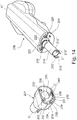
- the rotatable head 207 of the biopsy gun is detachably arranged on the biopsy gun body 220 as described below with reference to Figs. 14 and 15 .
- a through going passage 230 is provided along longitudinal axis C' - C' through the rotatable head 207.
- the passage 230 is dimensioned to accommodate the part of the cannula tube 210 extending outside the body 220.
- a guiding groove 231 is formed in the rotatable head 207 and a guide protrusion 221 extends from the biopsy gun body and has a size that allows it to run in the guiding groove, when the rotatable head is coupled to the biopsy gun.
- the guiding groove 231 is partly defined by spring arm 232 which may be deflected in a radial direction to the axis C' - C'. The function of the spring arm 232 will be described later.
- An annular track 222 extends around the cannula tube 210.
- the annular track is defined by the biopsy gun body and an annular track rim 223 extending around the cannula tube 210 in a distance from the biopsy gun body.
- Three track recesses 224 are formed in the track rim 223.
- Track protrusions 233 are formed on the inside of the through going passage 230.
- the track recesses 224 are arranged equiangular around the track rim 223.
- the track protrusions are formed equiangular around the inside of the through going passage 230.
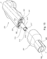
- the track recesses are slightly larger than the track protrusion in a way that the protrusions may pass through the recesses and into the track 222 when the axis C' - C' of the rotatable head 207 and the axis C" - C" of the biopsy gun body are co-axially arranged along the axis C - C, as shown in Fig. 15 and the protrusion and the recesses are aligned.
- the protrusions have a radial extent toward the longitudinal axis C - C which overlaps the radial extent of the track rim 223 away from axis C - C. This allows a locking engagement of the rotatable head and the biopsy gun body when the protrusions are arranged into the track and moved out of alignment with the recesses by rotating the rotatable head and the biopsy gun body relative to each other around axis C - C.
- the groove is divided into three sections, a release section 234, a loaded section 235 and a loading section 236.
- the release section 234 extends between a first end 237 of the groove and a first notch 238 extending radially inwards from the spring arm 232.
- the loaded section 235 extends between the first notch 238 and a second notch 239, which, like the first notch, also extends radially inwards from the spring arm.
- the loading section 236 extends between the second notch 239 and a second end 240 of the guiding groove.
- the guide protrusion 221 and the guide groove 231 limits the relative rotation of the part around longitudinal axis C - C.
- the relative position of the head 207 in respect of the body 220 thereby defines three positions of the biopsy gun; a release position wherein the guide protrusion is in release section 234; a loaded position wherein the guide protrusion is in the loaded section 235; and a loading position wherein the guide protrusion is in the loading section 236.
- First and second notches 238,239 are sized in a way that the guiding grooves narrows into a width that is smaller than the width of the guiding protrusion.
- the track protrusions 233 and the track recesses 224 are aligned and coupling and decoupling of the rotatable head and biopsy gun body is possible.
- first and second cannula tabs 150,151 on the biopsy needle may pass the first and second coupling tab 213',213" of the cannula tube 210 in order to be received in the first and second cannula groove 212',212"of the cannula tube 210.
- the rotatable head In the loaded position, the rotatable head is rotated, in a way that the first and second coupling tab 213',213" extend across the longitudinal extent of the first and second recesses 208,209 of the rotatable head.
- the first and second coupling tabs 213',213" engage the first and second cannula tabs 150,151 thereby securing the biopsy needle in the biopsy gun.
- the biopsy gun when used the biopsy gun is placed in the loading position wherein a biopsy needle is placed in the biopsy gun. Subsequently, the biopsy gun is placed in the loaded position wherein the biopsy gun may be used to retrieve a sample as described above. When a sample has been taken, the biopsy gun is placed back into its loading position whereafter the biopsy needle is removed. In case more samples are needed, then a new needle is inserted and the procedure is repeated.
- the biopsy gun is placed in its release position wherein the head is removed. Being able to remove the head is particularly advantageous for cleaning of the instrument. Especially, under some laws it is only required to clean/sterilize the part of the biopsy gun closest to the entry site into the patient, which in this case is the rotatable head. By being able to remove the head, only a small part has to be clean saving time and space.
- the biopsy gun is in the loaded position when the rotatable head is flush with the biopsy gun body such as shown in Fig.10 .
- the loaded position is then placed in the loading position and when the head is turned clockwise 45° relative to the body from the loaded position, then it is placed in the release position.
Description
- The invention relates to a kit comprising a biopsy needle wherein the cannula and stylet may be arranged in a locked position, preventing longitudinal movement relative to each other, and a reusable biopsy gun comprising means for moving the biopsy needle from its locked position to an unlocked position where the cannula and stylet may be moved in the longitudinal direction relative to each other.
- The use of a reusable biopsy gun and a biopsy needle comprises a number of steps.
- In a first step, the biopsy needle is loaded into the biopsy gun.
- In a second step the biopsy gun is armed, this is typically done by compressing two springs, one for the cannula of the biopsy needle and one for the stylet of the biopsy needle.
- In a third step the biopsy needle is inserted into the sampling site, e.g. soft tissue for example from the prostate, from which samples are desired.
- Finally, in a fourth step, the biopsy gun is fired, e.g. when the gun has been armed by springs these are released. This will result in the stylet being fired first. The stylet is provided with a small recess at the tip into which sample tissue will move. Secondly, the cannula is fired which cuts off the sample tissue and contains it in the recess. The biopsy needle is then pulled out of the body and the sample tissue may be retrieved.
- The steps may vary a little, and other steps may be introduced in between, however, most procedures generally follow the above.
- The present invention relates primarily to the first step. Loading of the biopsy needle into the biopsy gun comprises a number of handling issues. In particular because the nurse or surgeon has to handle two separate elements, one of which is very sharp and thus may involve unintentionally puncturing of the protective barrier, such as gloves, and even the tissue of the person loading the needle into the gun.
- In a number of known biopsy needles, the cannula and stylet are freely slidable relative to each other when loading the biopsy needle into the biopsy gun. This results in a high risk of the person handling the gun being pierced when loading the gun.
- In order to overcome this, some biopsy needles have been formed with locking members in order to prevent unintentional sliding movement between the cannula and the stylet. However, these comprise a third element which has to be removed before or after loading of the needle. Furthermore, during manufacture such a third element adds to the cost of the biopsy needle.
- Moreover, using such needles with known biopsy guns poses another problem in that the known biopsy guns are not adapted to handle such an additional element. Thus, the locking element has to be removed prior to loading, thereby removing the advantage of having a locked relationship between cannula and stylet during this step.
-
WO 2007/014904 discloses an automatic biopsy gun having first and second slides associated with a cannula and a stylet respectively, and comprising means for actuating the first and the second slides from respective forward configurations to respective retracted configurations. -
US5127419 discloses a biopsy instrument having a driving member slideably engaged with a track formed along the length of a housing. The driving member comprises proximal and distal slots which are notched at respective distal and proximal ends. - There is a need for providing a biopsy needle that solves the issues addressed above and a biopsy gun suitable for use with such a biopsy needle.
- An aspect of the invention is described in
claim 1. - This facilitates the loading of the biopsy needle into a biopsy gun as a biopsy needle is provided which is interchangeable between two positions, a locked position which is suitable when the biopsy needle is loaded into the biopsy gun without the operator having to be worried whether the stylet and the cannula will move relative to each other and an unlocked position wherein the biopsy needle is ready for use, i.e. the cannula and the stylet are movable relative to each other in the longitudinal direction.
- The biopsy needle is for use in the biopsy gun. The biopsy needle will typically be adapted for replaceable arrangement in the biopsy gun and in such configuration the biopsy needle will typically be a single use biopsy needle. However, in some cases the biopsy needle could be separately sterilized or otherwise cleaned in order for multiple uses.
- In one embodiment of the biopsy needle as described above, a stylet coupling part is arranged at the proximal end of the stylet, and a cannula coupling part is arranged at the proximal end of the cannula. The coupling parts are typically moulded onto the respective proximal ends, for example by injection moulding. The parts can be formed in many sizes and shapes suitable for the specific needs.
- This further facilitates the handling of the biopsy needle as the operator is able to manipulate the respective coupling parts instead of the sharp and often relatively thin stylet and cannula parts of the biopsy gun.
- Throughout the specification when using the word 'proximal' referral is made to an end of a part or element that is closest to user when the needle is inserted into the patient. The opposite end of the same part or element is referred to as the 'distal' end.
- In one embodiment, the rotatable movement of the stylet and the cannula relative to each other between the locked and the unlocked position can be provided by forming the cannula coupling part with a tubular coupling member having a tubular compartment for at least partly receiving the stylet coupling part, wherein the tubular compartment is formed with a track which engages with a protrusion formed on the stylet coupling part.
- The track thus functions as a limit for the protrusion, thereby controlling the relative movement between the cannula and the stylet. Thus, by defining the shape of the track, it is possible to limit the pattern and/or extent of movement between the cannula and the stylet.
- In one embodiment, the track is made up of at least a first and a second leg, the first leg extending circumferentially around the axis A - A, and the second leg extending longitudinally along the axis A - A.
- It can be understood that when the protrusion travels in the first leg which extends mainly transversely to the longitudinal axis A - A, movement of the cannula and the stylet relative to each other along the axis A - A is limited, however, when the protrusion moves into the second leg, the cannula and the stylet are freely movable relative to each other along the axis A - A within the extent of the second leg.
- In one embodiment, the biopsy needle is provided with a coupling arrangement which allows the protrusion to be moved between the first leg and the second leg via plastic deformation of at least one of the stylet coupling part or the cannula coupling part. This provides an added level of security, as additional force must be applied in order to move the biopsy needle between its locked and unlocked position.
- In another embodiment, at least one rib is arranged on an outer surface of either the cannula coupling part or the stylet coupling part, and at least one tab is arranged on an outer surface of the other coupling part.
- The rib and tab facilitate the rotational movement between the locked and unlocked position, as these function as gripping means. For example, an operator can easily manipulate the rib and tab relative to each other.
- Alternatively, a biopsy gun can comprise activation means for at least moving the biopsy needle from the locked position to the unlocked position. Such activation means can for example be provided by a protrusion in the housing of the biopsy gun, e.g. in the lid, which engages with either the rib or the tab when the biopsy gun is closed and thereby rotates the cannula and the stylet relative to each other by engagement of the rib or the tab with the protrusion.
- The kit may comprise a number of biopsy needles as described above and the biopsy gun for use with said biopsy needles.
- The invention relates to a kit comprising a biopsy gun and a biopsy needle. In particular, the invention relates to a kit comprising a biopsy gun where the biopsy needle may be front loaded.
- In such an aspect, the invention relates to a kit comprising a biopsy gun for loading, arming and firing a biopsy needle for receiving a biopsy sample, wherein the biopsy gun comprises a cannula slide adapted for engaging with a cannula of the biopsy needle and a stylet slide adapted for engaging with a stylet of the biopsy needle, the cannula slide and the stylet slide being slidable relative to each other along an axis C - C between a proximal end through which the biopsy needle extends out through the biopsy gun when the biopsy needle is inserted and a distal end, and where the cannula slide comprises cannula coupling means adapted for coupling with a cannula of the biopsy needle when the cannula slide and cannula are rotated relative to each other around axis C - C, and where the stylet slide comprises stylet coupling means adapted for coupling with a stylet of the biopsy needle when the stylet slide and stylet are rotated relative to each other around axis C - C.
- By using rotational coupling between the cannula and stylet of the biopsy needle and the respective slide, it is possible to provide front loading of the biopsy needle into the biopsy gun, i.e. the biopsy needle is introduced into the biopsy gun along the axis C - C, through the proximal end of the biopsy gun and then subsequently rotated into position. This provides an easy and intuitive loading of the biopsy gun.
- In one embodiment, in order to provide relative movement between the cannula and the stylet and their respective slides, the biopsy gun further comprises activation means for rotating a biopsy needle around the axis C - C.
- The stylet slide is in the form of a stylet tube extending along axis C - C, and the cannula slide is in the form of a cannular tube extending along axis C - C, the stylet tube being at least partly slidably arranged inside the cannula tube. This provides a compact design wherein the displacement of the respective slides is controlled.
- A number of different embodiments of the stylet and cannula coupling means may be provided. One such embodiment may be a bayonet type coupling which is safe and reliable. Thus, the biopsy gun at the proximal end of the stylet tube is formed with stylet coupling means in the form of at least one L-shaped stylet groove having a first leg extending longitudinal along axis C - C and a second leg extending transversely to the axis C - C, and wherein the proximal end of the cannula tube is formed with cannula coupling means in the form of at least one L-shaped cannula groove having a first leg extending longitudinal along axis C - C, and a second leg extending transversely to the axis C - C.
- In one embodiment, the activation means may be in the form of a rotatable head arranged at the proximal end of the biopsy gun, i.e. at the end where the biopsy needle is loaded into the biopsy gun. This provides simple operation of the biopsy gun, as the head may easily be rotated after the biopsy needle has been loaded and thereby preparing the biopsy gun for arming.
- In one embodiment, the rotatable head may function as a cover. This is advantageous since any blood or other liquid that runs from the introduction site and down along the biopsy needle will be caught by the head and this may be easily cleaned. In such embodiment, the rotatable head comprises a first through-going channel extending along axis C - C for receiving the biopsy needle.
- Different countries have different requirements for sterilizing and cleaning reusable medical equipment such as the biopsy gun as described herein. Some places it is only necessary to sterilize the point of first contact with body fluids. In such cases, it is advantageous that the rotatable head is detachably arranged on the biopsy gun. Thus, the rotatable head may be removed and sterilized separately, typically in an autoclave, thereby avoiding that the entire biopsy gun has to be sterilized.
- Thus, the invention relates to a kit comprising a biopsy gun as described above and at least one biopsy needle as described above for use with the biopsy gun.
-
-
Fig. 1 shows one embodiment of a biopsy needle as described herein, -
Fig. 2 shows another embodiment of a biopsy needle as described herein, -
Fig. 3 shows a top view of the biopsy needle ofFig. 2 along lines III - III, -
Fig. 4 shows an alternative position of the parts of the biopsy needle shown in the same view asFig. 3 , -
Fig. 5 shows, in perspective, a stylet of the biopsy needle ofFig. 2 - 4 , -
Fig. 6 shows, in perspective, a cannula of the biopsy needle ofFig. 2 - 4 , -
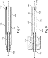
Fig. 7 shows the cannula ofFig. 6 in section along line VII - VII, -
Fig. 8 shows the cannula ofFig. 7 in section along line VIII - VIII, -
Fig. 9 shows, in exploded view, an embodiment of a biopsy gun to be used with the biopsy needles as described herein, -
Fig. 10 - 13 shows the biopsy gun and the biopsy needle in a coupled configuration wherein different parts have been hidden in order to facilitate understanding, and -
Fig. 14 and15 shows the biopsy gun in perspective with the rotatable head detached. - One embodiment of a
biopsy needle 1 extending along a longitudinal axis A - A is shown inFig.1 . - In the following, it should be understood that when referring to inner and outer surfaces of respective parts this is to be interpreted relative to the surface's orientation relative to the longitudinal axis A - A. Thus, an outer surface will face away from the longitudinal axis, while an inner surface will face towards the longitudinal axis.
- The
biopsy needle 1 comprises astylet 2 extending longitudinally between a proximal stylet end 3 and adistal stylet end 4. - The
stylet 2 terminates at thedistal stylet end 4 in astylet tip 5, which is sufficiently sharp to penetrate tissue. Further arranged at thedistal stylet end 4 is atissue recess 6 for receiving tissue samples during use of the biopsy needle. - The
biopsy needle 1 further comprises acannula 10 which extends longitudinally between aproximal cannula end 11 and adistal cannula end 12. Thecannula 10 is provided with a first through-goingtubular compartment 13 wherein at least a part of thestylet 2 may be received, or in other words thecannula 10 at least partly encloses thestylet 2, allowing the stylet to slide longitudinally along the axis A - A within thecannula 10. - The
cannula 10 terminates atdistal cannula end 12 in acannula tip 14, which is sufficiently sharp to penetrate tissue. - A
stylet coupling part 20 is attached to the proximal stylet end 3 at a distal styletcoupling part end 21. Thestylet coupling part 20 is cylindrically formed and extends longitudinally between the distal styletcoupling part end 21 and a proximal styletcoupling part end 22. - A
cannula coupling part 30 is attached to theproximal cannula end 11 at a distal cannulacoupling part end 31. Thecannula coupling part 30 extends longitudinally between the distal cannulacoupling part end 31 and a proximal cannularcoupling part end 32 and has a tubular cylindrical shape, defining a second through-goingtubular compartment 33 which is in communication with the first through-goingtubular compartment 13 and is capable of at least partly receiving thestylet 2 and thestylet coupling part 20. - A
track 34, e.g. in the shape of a groove or a through-going slot, is formed on the inner surface of thecannula coupling part 30, i.e. thetrack 34 opens out into the second through-goingtubular compartment 33. Thetrack 34 is formed of a first and asecond track leg first track leg 35 extends annularly around the longitudinal axis A - A in the form a half-circle transversely to the longitudinal axis. Thesecond track leg 36 extends from one end of thefirst track leg 35 in a direction along the longitudinal axis A - A. Thus, it can be understood that the track is L-shaped, where one of the legs of the L will curve and where the angle between the two legs are approximately 90°. However, other angles between the first and the second track leg can be provided, in particular angles between approximately 45° and 135°. - A
coupling protrusion 23 is provided on the outer surface of thestylet coupling part 20, at itsdistal end 21. Thecoupling protrusion 23 has a dimension which allows it to be received in thetrack 34. Thus, when thestylet coupling part 20 is arranged in the second through-goingtubular compartment 33 of thecannula coupling part 30 so that thecoupling protrusion 23 extends into thetrack 34, the movement of thestylet 2 and thecannula 6 will be limited to the shape of thetrack 34. - In the current embodiment, the shape of the
track 34 will thus limit relative movement between thestylet 2 and thecannula 6 along the longitudinal axis A - A, while thecoupling protrusion 23 runs in thefirst track leg 35, which extends transverse to the longitudinal direction. In other words, the biopsy needle can be considered to be in a locked position wherein relative movement between the stylet and the cannula along the axis A - A is prevented. - However, by rotating the
stylet 2 and thecannula 6 relative to each other around the axis A - A, thecoupling protrusion 23 can be moved into thesecond track leg 36, which extends along the longitudinal direction. Thus, the biopsy needle can be considered to be in an unlocked position wherein relative movement between thestylet 2 and thecannula 6 along the axis A - A is enabled. - The biopsy needle as described above will typically be used in a biopsy gun (not shown) suitable for reuse, while the biopsy needle will be discarded after use.
- Typical biopsy guns are formed with two slides on which the
stylet coupling part 20 and thecannula coupling part 30 are placed, respectively. As is commonly known, such slides are individually moveable in order to move thestylet 2 and thecannula 10 relative each other. - Protruding from opposite sides of the outer surface of the
cannula coupling part 30, a first and asecond rib cannula coupling part 30, and thereby thecannula 6, is prevented from unintentionally rotating around the longitudinal axis. - Protruding from opposite sides of the outer surface of the
stylet coupling part 20, a first and asecond tab - When the
biopsy needle 1 has been arranged in the biopsy gun, i.e. thestylet coupling part 20 and thecannula coupling part 30 have been placed on the respective slides, thestylet coupling part 20 may be rotated around the longitudinally axis, moving the biopsy needle from its locked position to its unlocked position. - The first and the
second tab stylet coupling part 20. - Thus, it can be understood that the biopsy needle can easily be arranged in the biopsy gun, without having to keep track of the relative placement of the stylet coupling part and the cannula coupling part, as these are locked. When arranged in the biopsy gun, the coupling parts are unlocked relative to each other and the biopsy needle is thus ready to use.
- A second embodiment of the
biopsy needle 101 extending along a longitudinal axis B - B is shown infigs. 2 - 6 . - As with the first embodiment described above, it should be understood that when referring to inner and outer surfaces of respective parts this is to be interpreted relative to the surface's orientation relative to the longitudinal axis B - B. Thus, an outer surface will face away from the longitudinal axis, while an inner surface will face towards the longitudinal axis.
- The
biopsy needle 101 comprises astylet 102 extending longitudinally between aproximal stylet end 103 and adistal stylet end 104. - The
stylet 102 terminates at thedistal stylet end 104 in astylet tip 105, which is sufficiently sharp to penetrate tissue. Further arranged at thedistal stylet end 104 is atissue recess 106 for receiving tissue samples during use of the biopsy needle. - The
biopsy needle 101 further comprises acannula 110, which extends longitudinally between aproximal cannula end 111 and adistal cannula end 112. Thecannula 110 is provided with a first through-goingtubular compartment 113 wherein at least a part of thestylet 102 may be received, or in other words, thecannula 110 at least partly encloses thestylet 102, allowing the stylet to slide longitudinally along the axis B - B within thecannula 110. - The
cannula 110 terminates at thedistal cannula end 112 in acannula tip 114, which is sufficiently sharp to penetrate tissue. - A
stylet coupling part 120 is attached to theproximal stylet end 103 at a distal styletcoupling part end 121. Thestylet coupling part 120 is cylindrically formed and extends longitudinally between the distal styletcoupling part end 121 and a proximal styletcoupling part end 122. - A
cannula coupling part 130 is attached to theproximal cannula end 111 at a distal cannulacoupling part end 131. Thecannula coupling part 130 extends longitudinally between the distal cannulacoupling part end 131 and a proximal cannularcoupling part end 132 and has a tubular cylindrical shape, defining a second through-goingtubular compartment 133 which is in communication with the first through-goingtubular compartment 113 and is capable of at least partly receiving thestylet 102 and thestylet coupling part 120. - A
track 134, e.g. in the shape of a groove or a through-going slot, is formed on the inner surface of thecannula coupling part 130 so that thetrack 134 opens out into the second through-goingtubular compartment 133. Thetrack 134 is formed of alongitudinal track leg 135 and atrack recess 136 formed at the distal end of the longitudinal track leg and extending annularly around the longitudinal axis, or in other words thetrack recess 136 extends transverse from thelongitudinal track leg 135. Similar to the first embodiment described above, thetrack 134 can be viewed as being L-shaped, where thetrack recess 136 will slightly curve and where the angle between the two legs is approximately 90°. However, other angles between the first and the second track leg can be provided, in particular angles between approximately 45° and 135°. - A
coupling protrusion 123 is provided on the outer surface of thestylet coupling part 120, at itsdistal end 121. Thecoupling protrusion 123 has a dimension which allows it to be received in thetrack 134. Thus, when thestylet coupling part 120 is arranged in second through-goingtubular compartment 133 of thecannula coupling part 130 so that thecoupling protrusion 123 extends into thetrack 134, the movement of thestylet 102 and thecannula 106 will be limited to the shape of thetrack 134. - Extending longitudinally and in a proximal direction from the
coupling protrusion 123, afirst locking rib 140 is provided on the outer surface of thestylet coupling part 120. Extending longitudinal and in a proximal direction from thelongitudinal track leg 135, asurface recess 142 is provided on the inner surface of the cannula coupling part. Said surface recess has a depth which allows thefirst locking rib 140 to move freely therein, when thestylet coupling part 120 is arranged in thecannula coupling part 130. Asecond locking rib 141 is provided in the surface recess on the inner surface of thecannula coupling part 130. - When the
stylet coupling part 120 is arranged in thecannula coupling part 130, the first and the second locking rib are so dimensioned that they will abut against each other. However, by applying some force, plastic deformation may occur and the two locking ribs can pass each other, making it possible to arrange the stylet coupling part and the cannula coupling part in two distinct positions. In itself, this principle is generally known and is, for example, used in coupling arrangements such as in lids for markers and pens and a large number of other applications where at least one part is plastically deformed in order to fit or pass another part. A person skilled in the art would know how to dimension the first and the second locking ring depending on the material used in order to achieve the desired force required for the two locking ribs to pass each other. - In the second embodiment, a locked position can thus be provided wherein relative movement between the stylet and the cannula along the axis B - B is prevented as the
coupling protrusion 123 is retained in thetrack recess 136 by first and second locking ribs. Then, by applying a predetermined amount of torque force, i.e. rotating thestylet coupling part 120 and thecannula coupling part 130 with respect to each other, the two locking ribs pass each other and the coupling protrusion is moved out of thetrack recess 136 and into the longitudinal track leg, thereby placing the biopsy needle in an unlocked position wherein relative movement between the stylet and the cannula along the axis B - B is enabled. - In
fig. 3 , which is a top view along line III-III infig. 2 , it is shown how thefirst locking rib 140 and thesecond locking rib 141 are positioned relative to each other when the biopsy needle is in its unlocked position, i.e. thecoupling protrusion 123 is arranged in thelongitudinal track leg 135. - In
fig. 4 , a top view of the biopsy needle, corresponding to that offig. 3 , is shown where the biopsy needle is in its locked position. Here, it can be seen that the first and second locking ribs are arranged opposite their relative position in the unlocked position whereby thecoupling protrusion 123 is at least partly arranged in thetrack recess 136. - The biopsy needle as described above will typically be used in a biopsy gun (not shown) suitable for reuse while the biopsy needle will be discarded after use.
- As described above with respect to the first embodiment, typical biopsy guns are formed with two slides on which the
stylet coupling part 120 and thecannula coupling part 130 are placed, respectively. As is commonly known, such slides are individually moveable in order to move thestylet 102 and thecannula 110 relative each other. - Protruding from opposite sides of the outer surface of the
cannula coupling part 130, a first and asecond rib cannula coupling part 130, and thereby thecannula 106, is prevented from unintentionally rotating around the longitudinal axis. - Protruding from opposite sides of the outer surface of the
stylet coupling part 120, a first and asecond tab - When the
biopsy needle 101 has been arranged in the biopsy gun, i.e. thestylet coupling part 120 and thecannula coupling part 130 have been placed on the respective slides, thestylet coupling part 120 may be rotated around the longitudinally axis, moving the biopsy needle from its locked position to its unlocked position. - The first and the
second tab stylet coupling part 120. - Thus, it can be understood that the biopsy needle can easily be arranged in the biopsy gun without having to keep track of the relative placement of the stylet coupling part and the cannula coupling part, as these are locked. When arranged in the biopsy gun, the coupling parts are unlocked relative to each other and the biopsy needle is thus ready to use.
-
Fig. 9 - 15 shows abiopsy gun 200 which is particularly suited for use with thebiopsy needle 101 as described above with reference toFigs. 2 - 8 . - In
Fig. 9 , thebiopsy gun 200 is shown in exploded view. The biopsy gun comprises a housing in the form of anupper part 201 and alower part 202. Within thehousing gun mechanics 203 are contained. - The housing can be removed partially or completely in order to have access to the
mechanical system 203, for example in order to clean it or change parts. - The gun has an arming
slider 204 which is used for arming the biopsy needle and tworelease buttons 205', 205". - A
safety switch 206 is provided which is movable between a safe position wherein firing of the biopsy gun is not possible and a release position wherein firing of the biopsy gun is allowed. - A
rotatable head 207 is arranged at the proximal end of the biopsy gun. The rotatable head is rotatable around axis C - C of the biopsy gun. A first andsecond recess rotatable head 207 for receiving the first andsecond rib biopsy needle 101. Thus, when the head is rotated the biopsy needle is rotated along with it. -
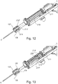
Figs. 10 - 13 shows, in section, the biopsy gun and biopsy needle seen from above, i.e. looking down on theupper part 201 of the housing. - In order to facilitate viewing,
Figs. 11 - 13 are shown with some parts hidden. InFigs. 11 - 13 thehousing Fig. 12 , therotatable head 207 is hidden andfig. 13 further hides thecannula tube 210. - A cannula slide in the form of a
cannula tube 210 and a stylet slide in the form of astylet tube 211 are provided in the gun mechanics. - A first and
second cannula groove 212', 212" are provided in the proximal end of thecannula tube 210. The cannula grooves are L-shaped resulting in a first and a secondcannula coupling tab 213', 213". - A first and a
second stylet groove 214', 214" are provided in the proximal end of thestylet tube 211. The stylet grooves are L-shaped resulting in a first and a secondstylet coupling tab 215', 215". - It should be understood that the L-shaped grooves are so dimensioned that a first leg extends parallel to the longitudinal axis C - C from the proximal edge of the respective tubes, and then continues into a second leg that extends transversely to the longitudinal axis C - C, thereby providing an L-shape.
- When loading the biopsy needle, the rotatable head is rotated approximately 90° around axis C - C which allows the biopsy needle to be inserted into the biopsy gun in such a way that the first and the second stylet tab 124,125 of the biopsy needle are received within the first legs of the stylet grooves, the first and the second cannula tab 150,151 are received within the first legs of the cannula grooves and the first and the second rib are received in the first and second recess 208,209 of the rotatable head.
- Thus, when the head is rotated approximately 90° into the position as shown in
Figs. 10 - 13 , the first and the second recesses will engage with the first and the second rib, thereby turning the biopsy needle around the axis C - C, corresponding to the axis B - B of the biopsy needle. This results in the first and the second stylet tab 124,125 being moved into the second leg of the stylet grooves, and the first and the second cannula tabs 150,151 are moved into the second leg of the cannula groove. This bayonet coupling between the respective tabs and grooves couples the cannula with the cannula slide and the stylet with the stylet slide. - Furthermore, by providing a difference in the length of the second leg of the cannula grooves compared to the stylet groove, it is possible to move the biopsy needle from its locked position to its unlocked position in the same rotation as it takes to couple the cannula and stylet with their respective slides. This provides an intuitive and all-in-one step for the surgeon, thereby facilitating the use of the biopsy gun. In the present embodiment, this is achieved by having the second legs of the cannula grooves so much longer that the first and second stylet tabs will reach the bottom of the second leg of the stylet grooves before the first and second cannula tabs reach the bottom of the second leg of the cannula grooves.
- With the biopsy needle loaded into the biopsy gun and in the unlocked position, it is now possible for the surgeon to arm the biopsy gun, insert it into the sample site and fire it in order to retrieve a sample.
- Arming of the biopsy gun is typically performed as a two-step process. In the first step the arming
slider 204 is pulled back along axis C - C. Engagement means (not shown) couples the arming slider with the cannula slider, e.g. thecannula tube 210, resulting in the fact that the cannula slider is pulled back together with the arming slider. As the cannula slider is pulled back the cannula firing means are tensioned. Such firing means are typically in the form of a cannula spring 300. When pulled back to a desired position the cannula slider and the cannula spring are locked in this position. This position is also referred to as the armed position of the cannula slider. - After arming the cannula slider, the arming slider uncouples from the cannula slider. Such uncoupling can be realised in different ways, many of which are already teached within the art. One way is to provide a track (not shown), which guides the arming slider and thus guides the arming slider away from the cannula slider after the cannula slider has been armed.
- The arming slider is then pushed forward. This can be done by the surgeon, or a spring may pull the arming slider forward where it engages the stylet slider. The stylet slider is then moved into its armed position in the same manner as the cannula slider.
- With both the cannula slider and the stylet slider in their respective armed positions, the biopsy gun is now considered armed.
- The surgeon may now insert the needle into the sample site and fire the biopsy gun in order to retrieve a sample.
- When inserted, the surgeon pushes one of the
release buttons 205', 205". When pressed, the release button unlocks the stylet slider from its arming position. The force released by the stylet firing means, such as a spring, fires the stylet slider forward. A small recess (not shown) at the tip of the stylet is provided wherein tissue is received. - When the stylet slider is fired it will trigger the release of the cannula slider which fires the cannula. The cannula separated the tissue in the recess and the biopsy needle may then be retracted and the tissue sample in the recess removed for analysis.
- These subsequent steps following the loading of the biopsy needle are executed as taught in the art and thus do not separately form part of this invention. For example, as mentioned, the arming may be done by applying techniques well-known in the art such as spring loading of both the stylet slide and the cannula slide.
- The use of tubes for the two slides is advantageous as they provide an even rotation of the cannula when the cannula and the rotatable head are rotated relative to each other. Although other shapes and elements may be used, these will typically require detailed design and special consideration in order to function correctly.
- Moreover, when the cannula tube is formed as a tube, it may function as a guide for the stylet tube.
- Another advantage of the embodiment of the biopsy gun as described is that the
rotatable head 207 of the biopsy gun is detachably arranged on thebiopsy gun body 220 as described below with reference toFigs. 14 and15 . - A through going
passage 230 is provided along longitudinal axis C' - C' through therotatable head 207. Thepassage 230 is dimensioned to accommodate the part of thecannula tube 210 extending outside thebody 220. - A guiding
groove 231 is formed in therotatable head 207 and aguide protrusion 221 extends from the biopsy gun body and has a size that allows it to run in the guiding groove, when the rotatable head is coupled to the biopsy gun. The guidinggroove 231 is partly defined byspring arm 232 which may be deflected in a radial direction to the axis C' - C'. The function of thespring arm 232 will be described later. - An
annular track 222 extends around thecannula tube 210. The annular track is defined by the biopsy gun body and anannular track rim 223 extending around thecannula tube 210 in a distance from the biopsy gun body. Three track recesses 224 are formed in thetrack rim 223.Track protrusions 233 are formed on the inside of the through goingpassage 230. - The track recesses 224 are arranged equiangular around the
track rim 223. The track protrusions are formed equiangular around the inside of the through goingpassage 230. The track recesses are slightly larger than the track protrusion in a way that the protrusions may pass through the recesses and into thetrack 222 when the axis C' - C' of therotatable head 207 and the axis C" - C" of the biopsy gun body are co-axially arranged along the axis C - C, as shown inFig. 15 and the protrusion and the recesses are aligned. The protrusions have a radial extent toward the longitudinal axis C - C which overlaps the radial extent of thetrack rim 223 away from axis C - C. This allows a locking engagement of the rotatable head and the biopsy gun body when the protrusions are arranged into the track and moved out of alignment with the recesses by rotating the rotatable head and the biopsy gun body relative to each other around axis C - C. - During coupling of the rotatable head and the biopsy gun body the guiding
groove 231 and theguide protrusion 221 limits the rotational movement of the head and the body as the protrusion is only allowed to move within the groove. The groove is divided into three sections, arelease section 234, a loadedsection 235 and aloading section 236. Therelease section 234 extends between afirst end 237 of the groove and afirst notch 238 extending radially inwards from thespring arm 232. The loadedsection 235 extends between thefirst notch 238 and asecond notch 239, which, like the first notch, also extends radially inwards from the spring arm. Theloading section 236 extends between thesecond notch 239 and asecond end 240 of the guiding groove. - Thus, when the biopsy head and body are coupled together, the
guide protrusion 221 and theguide groove 231 limits the relative rotation of the part around longitudinal axis C - C. The relative position of thehead 207 in respect of thebody 220 thereby defines three positions of the biopsy gun; a release position wherein the guide protrusion is inrelease section 234; a loaded position wherein the guide protrusion is in the loadedsection 235; and a loading position wherein the guide protrusion is in theloading section 236. - First and second notches 238,239 are sized in a way that the guiding grooves narrows into a width that is smaller than the width of the guiding protrusion. Thus, when the head and body are rotated relative to each other, the protrusion will come into contact with the respective notches, as it moves between sections. The user then has to use additional forces in order to deflect the
spring arm 232 and thereby allowing the protrusion to pass the respective notch. This has the advantage that the user is given a clear indication of when the biopsy gun is in one of the three positions described above. Further, this also prevents that the gun unintentionally moves between positions. - In the release position, the
track protrusions 233 and the track recesses 224 are aligned and coupling and decoupling of the rotatable head and biopsy gun body is possible. - In the loading position it is possible to insert a biopsy needle as described herein, in a way that the first and second cannula tabs 150,151 on the biopsy needle may pass the first and
second coupling tab 213',213" of thecannula tube 210 in order to be received in the first andsecond cannula groove 212',212"of thecannula tube 210. - In the loaded position, the rotatable head is rotated, in a way that the first and
second coupling tab 213',213" extend across the longitudinal extent of the first and second recesses 208,209 of the rotatable head. In other words, when the biopsy needle as described herein is placed in the biopsy gun and the first and second ribs 137,138 are received in the first and second recesses then the first andsecond coupling tabs 213',213" engage the first and second cannula tabs 150,151 thereby securing the biopsy needle in the biopsy gun. - Accordingly, when used the biopsy gun is placed in the loading position wherein a biopsy needle is placed in the biopsy gun. Subsequently, the biopsy gun is placed in the loaded position wherein the biopsy gun may be used to retrieve a sample as described above. When a sample has been taken, the biopsy gun is placed back into its loading position whereafter the biopsy needle is removed. In case more samples are needed, then a new needle is inserted and the procedure is repeated.
- However, if the procedure is over and the biopsy needle removed, then the biopsy gun is placed in its release position wherein the head is removed. Being able to remove the head is particularly advantageous for cleaning of the instrument. Especially, under some laws it is only required to clean/sterilize the part of the biopsy gun closest to the entry site into the patient, which in this case is the rotatable head. By being able to remove the head, only a small part has to be clean saving time and space.
- In the described embodiment, the biopsy gun is in the loaded position when the rotatable head is flush with the biopsy gun body such as shown in
Fig.10 . When the head is turned counter clockwise 90° relative to the body form, the loaded position is then placed in the loading position and when the head is turned clockwise 45° relative to the body from the loaded position, then it is placed in the release position.
Claims (14)
- A kit comprising a biopsy needle (101) and a biopsy gun (200) for loading, arming and firing the biopsy needle (101) for receiving a biopsy sample, wherein the biopsy gun (200) comprises a cannula slide adapted for engaging with a cannula of the biopsy needle (101) and a stylet slide adapted for engaging with a stylet (102) of the biopsy needle (101), the cannula slide and the stylet slide being slidable relative to each other along a longitudinal axis between a proximal end through which the biopsy needle (101) extends out through the biopsy gun (200) when the biopsy needle (101) is inserted and a distal end, and where the cannula slide comprises cannula coupling means adapted for coupling with a cannula (110) of the biopsy needle (101) when the cannula slide and cannula (110) are rotated relative to each other around the longitudinal axis, and where the stylet slide comprises stylet coupling means adapted for coupling with the stylet (102) of the biopsy needle (101) when the stylet slide and stylet (102) are rotated relative to each other around the longitudinal axis,
the stylet (102) extending along the longitudinal axis between a proximal stylet end (103) and a distal stylet end (104) and the cannula (110) extending along the longitudinal axis between a proximal cannula end (111) and a distal cannula end (112) at least partly enclosing the stylet (102), wherein the stylet (102) and the cannula (110) are rotatable relative to each other around the longitudinal axis between- a locked position, wherein relative movement between the stylet (102) and the cannula (110) along the longitudinal axis is prevented, and- an unlocked position, wherein relative movement between the stylet (102) and the cannula (110) along the longitudinal axis is enabled,wherein the stylet slide is in the form of a stylet tube (211) extending along the longitudinal axis, and the cannula slide is in the form of a cannula tube (210) extending along the longitudinal axis, the stylet tube (211) being at least partly slidably arranged inside the cannula tube (210),
wherein the proximal end of the stylet tube (211) is formed with the stylet coupling means in the form of at least one L-shaped stylet groove (214', 214") having a first leg extending longitudinally along longitudinal axis and a second leg extending transversely to the longitudinal axis, and wherein the proximal end of the cannula tube (210) is formed with the cannula coupling means in the form of at least one L-shaped cannula groove (212', 212") having a first leg extending longitudinally along longitudinal axis, and a second leg extending transversely to the longitudinal axis. - A kit according to claim 1, wherein the biopsy gun (200) further comprises activation means for rotating the biopsy needle (101) around the longitudinal axis.
- A kit according to any of claims 1 or 2, wherein the activation means are in the form of a rotatable head (207) arranged at the proximal end of the biopsy gun (200).
- A kit according to claim 3, wherein the rotatable head (207) comprises a first through-going channel (230) extending along the longitudinal axis for receiving the biopsy needle.
- A kit according to claim 3 or 4, wherein the rotatable head (207) is detachably arranged on the biopsy gun (200).
- A kit according to claim 3, 4 or 5, wherein the rotatable head (207) comprises a first and a second recess (208, 209) for receiving a first and a second rib (137, 138) of the biopsy needle (101).
- A kit according to any one of claims 3, 4, 5 or 6, wherein a guiding groove (231) is formed in the rotatable head (207) and a guide protrusion (221) extends from the biopsy gun body (220) and has a size allowing it to run in the guiding groove (231), when the rotatable head (207) is coupled to the biopsy gun (200).
- A kit according to claim 7, wherein the guiding groove (231) is divided into three sections; a release section (234), a loaded section (235) and a loading section (236).
- A kit according to claim 8, wherein a relative position of the rotatable head (207) in relation to the biopsy gun (220) defines three positions of the biopsy gun (220):- a release position wherein the guide protrusion (221) is in release section (234),- a loaded position wherein the guide protrusion (221) is in the loaded section (235), and- a loading position wherein the guide protrusion (221) is in the loading section (236).
- A kit according to claim 9, wherein the biopsy gun (200) is in the loaded position when the rotatable head (207) is flush with the biopsy gun body (220).
- A kit according to claim 9, wherein, when the rotatable head (207) is turned 90° counter clockwise relative to the biopsy gun body (220), the biopsy gun (200) is in the loading position.
- A kit according to claim 9, wherein, when the rotatable head (207) is turned 45° clockwise relative to the biopsy gun body (220) from the loaded position, the biopsy gun (200) is in the release position.
- A kit according to claim 1, wherein the second leg of the cannula grooves (212', 212") is different in length compared to the stylet groove (214', 214").
- A kit according to claim 13, wherein the second legs of the cannula grooves (212', 212") are so much longer than the stylet grooves (214', 214") that first and second stylet tabs (124, 125) reach a bottom of the second leg of the stylet grooves (214', 214") before first and second cannula tabs (150, 151) reach a bottom of the second leg of the cannula grooves (212', 212").
Priority Applications (1)
| Application Number | Priority Date | Filing Date | Title |
|---|---|---|---|
| EP16153732.9A EP3045119B1 (en) | 2009-08-12 | 2010-08-12 | Reusable biopsy gun and a lockable biopsy needle for use therewith |
Applications Claiming Priority (4)
| Application Number | Priority Date | Filing Date | Title |
|---|---|---|---|
| EP09290626A EP2283776A1 (en) | 2009-08-12 | 2009-08-12 | Biopsy needle |
| EP10290244 | 2010-05-06 | ||
| EP10744861.5A EP2464295B1 (en) | 2009-08-12 | 2010-08-12 | Reusable biopsy gun and a lockable biopsy needle for use therewith |
| EP16153732.9A EP3045119B1 (en) | 2009-08-12 | 2010-08-12 | Reusable biopsy gun and a lockable biopsy needle for use therewith |
Related Parent Applications (2)
| Application Number | Title | Priority Date | Filing Date |
|---|---|---|---|
| EP10744861.5A Division EP2464295B1 (en) | 2009-08-12 | 2010-08-12 | Reusable biopsy gun and a lockable biopsy needle for use therewith |
| EP10744861.5A Division-Into EP2464295B1 (en) | 2009-08-12 | 2010-08-12 | Reusable biopsy gun and a lockable biopsy needle for use therewith |
Publications (2)
| Publication Number | Publication Date |
|---|---|
| EP3045119A1 EP3045119A1 (en) | 2016-07-20 |
| EP3045119B1 true EP3045119B1 (en) | 2018-04-18 |
Family
ID=42769588
Family Applications (2)
| Application Number | Title | Priority Date | Filing Date |
|---|---|---|---|
| EP16153732.9A Active EP3045119B1 (en) | 2009-08-12 | 2010-08-12 | Reusable biopsy gun and a lockable biopsy needle for use therewith |
| EP10744861.5A Active EP2464295B1 (en) | 2009-08-12 | 2010-08-12 | Reusable biopsy gun and a lockable biopsy needle for use therewith |
Family Applications After (1)
| Application Number | Title | Priority Date | Filing Date |
|---|---|---|---|
| EP10744861.5A Active EP2464295B1 (en) | 2009-08-12 | 2010-08-12 | Reusable biopsy gun and a lockable biopsy needle for use therewith |
Country Status (4)
| Country | Link |
|---|---|
| US (2) | US20120130276A1 (en) |
| EP (2) | EP3045119B1 (en) |
| ES (2) | ES2677258T3 (en) |
| WO (1) | WO2011018091A1 (en) |
Families Citing this family (7)
| Publication number | Priority date | Publication date | Assignee | Title |
|---|---|---|---|---|
| JP5379249B2 (en) * | 2012-01-13 | 2013-12-25 | 富士フイルム株式会社 | Tissue collection device |
| ES2616502T3 (en) * | 2012-01-16 | 2017-06-13 | Coloplast A/S | Device to take at least one tissue sample |
| US20160324507A1 (en) * | 2013-11-18 | 2016-11-10 | Moller Medical Gmbh | Sampling unit, sampling device and method for collecting a sample |
| CN111067578B (en) * | 2020-01-17 | 2023-07-18 | 普昂(杭州)医疗科技有限公司 | Biopsy device of safe puncture |
| US20240023944A1 (en) * | 2020-12-10 | 2024-01-25 | National University Hospital (Singapore) Pte Ltd | Core needle biopsy device |
| CN114533145B (en) * | 2022-03-02 | 2023-07-14 | 浙江伽奈维医疗科技有限公司 | Biopsy gun |
| CN115211905A (en) * | 2022-07-11 | 2022-10-21 | 经方精密医疗(深圳)有限公司 | Biopsy needle |
Family Cites Families (18)
| Publication number | Priority date | Publication date | Assignee | Title |
|---|---|---|---|---|
| US5172701A (en) * | 1990-02-28 | 1992-12-22 | Medical Device Technologies, Inc. | Single use automated soft tissue aspiration biopsy device |
| US5127419A (en) * | 1991-07-02 | 1992-07-07 | Antoine Kaldany | Biopsy instrument with slotted driving member |
| US5195533A (en) * | 1992-05-08 | 1993-03-23 | Boston Scientific Corporation | Biopsy needle instrument for storing multiple specimens |
| US5425376A (en) * | 1993-09-08 | 1995-06-20 | Sofamor Danek Properties, Inc. | Method and apparatus for obtaining a biopsy sample |
| US5649547A (en) * | 1994-03-24 | 1997-07-22 | Biopsys Medical, Inc. | Methods and devices for automated biopsy and collection of soft tissue |
| US5570699A (en) * | 1994-04-26 | 1996-11-05 | Kass; Erik S. | Controlled surgical core biopsy system |
| US5531701A (en) * | 1994-06-06 | 1996-07-02 | Luther Medical Products, Inc. | Over-the-needle catheter |
| US6749576B2 (en) * | 1996-01-26 | 2004-06-15 | Allegiance Corporation | Biopsy device with adjustable sampling |
| US5876354A (en) * | 1996-05-01 | 1999-03-02 | Emx | Biopsy needle hub assembly |
| DE19915857A1 (en) * | 1999-04-08 | 2000-10-12 | Pajunk Gmbh | Biopsy needle, needle holder and biopsy system |
| EP1524940B1 (en) * | 2002-03-19 | 2011-08-24 | Bard Dublin ITC Limited | Biopsy device and biopsy needle module that can be inserted into the biopsy device |
| DE602004013450T2 (en) * | 2004-11-25 | 2009-06-04 | Carro, Luigi, Rudiano | Gripping member for biomezidinische needle |
| ITMO20050198A1 (en) * | 2005-07-29 | 2007-01-30 | Medax S R L | AUTOMATIC GUN FOR BIOPSIES |
| BRMU8600004Y1 (en) * | 2006-01-03 | 2014-12-09 | Eugenio Machado De Andrade | PROVISION INTRODUCED IN BIOPSY AND SIMILAR SAMPLE COLLECTOR |
| US8480595B2 (en) * | 2006-12-13 | 2013-07-09 | Devicor Medical Products, Inc. | Biopsy device with motorized needle cocking |
| CA2637555A1 (en) * | 2007-07-16 | 2009-01-16 | Inrad, Inc. | Coaxial needle assembly |
| EP2205170A2 (en) * | 2007-10-31 | 2010-07-14 | Stanley I. Kim | Rotating biopsy device and biopsy robot |
| US8052616B2 (en) * | 2007-11-20 | 2011-11-08 | Devicor Medical Products, Inc. | Biopsy device with fine pitch drive train |
-
2010
- 2010-08-12 WO PCT/DK2010/050208 patent/WO2011018091A1/en active Application Filing
- 2010-08-12 ES ES16153732.9T patent/ES2677258T3/en active Active
- 2010-08-12 EP EP16153732.9A patent/EP3045119B1/en active Active
- 2010-08-12 EP EP10744861.5A patent/EP2464295B1/en active Active
- 2010-08-12 US US13/389,804 patent/US20120130276A1/en not_active Abandoned
- 2010-08-12 ES ES10744861.5T patent/ES2601209T3/en active Active
-
2015
- 2015-02-06 US US14/615,513 patent/US9125637B2/en active Active
Non-Patent Citations (1)
| Title |
|---|
| None * |
Also Published As
| Publication number | Publication date |
|---|---|
| EP2464295A1 (en) | 2012-06-20 |
| EP3045119A1 (en) | 2016-07-20 |
| US20150150543A1 (en) | 2015-06-04 |
| US9125637B2 (en) | 2015-09-08 |
| ES2601209T3 (en) | 2017-02-14 |
| US20120130276A1 (en) | 2012-05-24 |
| ES2677258T3 (en) | 2018-07-31 |
| EP2464295B1 (en) | 2016-08-03 |
| WO2011018091A1 (en) | 2011-02-17 |
Similar Documents
| Publication | Publication Date | Title |
|---|---|---|
| US9125637B2 (en) | Method of loading a locked tissue biopsy needle into a biopsy gun | |
| US8348894B2 (en) | Needle assembly including obturator with safety reset | |
| US7850650B2 (en) | Needle safety shield with reset | |
| AU704186B2 (en) | Universal handle for medical instruments | |
| US20070073244A1 (en) | Needle assembly including obturator with safety reset | |
| US20210093358A1 (en) | Step Needle for Intraosseous Access Device | |
| MXPA06007722A (en) | Device for shielding a sharp tip of a cannula and method of using the same. | |
| US10278684B2 (en) | Surgical apparatus comprising magazine | |
| CN108472061B (en) | Multi-head storage magazine for use with surgical devices | |
| US11684756B2 (en) | Catheter assembly | |
| US5921943A (en) | Controlled surgical core biopsy system | |
| CA2595683C (en) | Needle assembly including obturator with safety reset | |
| EP2788056B1 (en) | A sharps retraction device | |
| WO2022158406A1 (en) | Operating device and implant indwelling tool | |
| EP2283776A1 (en) | Biopsy needle | |
| EP1907034A2 (en) | Needle assembly including obturator with safety reset |
Legal Events
| Date | Code | Title | Description |
|---|---|---|---|
| PUAI | Public reference made under article 153(3) epc to a published international application that has entered the european phase |
Free format text: ORIGINAL CODE: 0009012 |
|
| AC | Divisional application: reference to earlier application |
Ref document number: 2464295 Country of ref document: EP Kind code of ref document: P |
|
| AK | Designated contracting states |
Kind code of ref document: A1 Designated state(s): AL AT BE BG CH CY CZ DE DK EE ES FI FR GB GR HR HU IE IS IT LI LT LU LV MC MK MT NL NO PL PT RO SE SI SK SM TR |
|
| 17P | Request for examination filed |
Effective date: 20170120 |
|
| RBV | Designated contracting states (corrected) |
Designated state(s): AL AT BE BG CH CY CZ DE DK EE ES FI FR GB GR HR HU IE IS IT LI LT LU LV MC MK MT NL NO PL PT RO SE SI SK SM TR |
|
| GRAP | Despatch of communication of intention to grant a patent |
Free format text: ORIGINAL CODE: EPIDOSNIGR1 |
|
| INTG | Intention to grant announced |
Effective date: 20171024 |
|
| GRAS | Grant fee paid |
Free format text: ORIGINAL CODE: EPIDOSNIGR3 |
|
| GRAA | (expected) grant |
Free format text: ORIGINAL CODE: 0009210 |
|
| AC | Divisional application: reference to earlier application |
Ref document number: 2464295 Country of ref document: EP Kind code of ref document: P |
|
| AK | Designated contracting states |
Kind code of ref document: B1 Designated state(s): AL AT BE BG CH CY CZ DE DK EE ES FI FR GB GR HR HU IE IS IT LI LT LU LV MC MK MT NL NO PL PT RO SE SI SK SM TR |
|
| REG | Reference to a national code |
Ref country code: GB Ref legal event code: FG4D |
|
| REG | Reference to a national code |
Ref country code: CH Ref legal event code: EP |
|
| REG | Reference to a national code |
Ref country code: AT Ref legal event code: REF Ref document number: 989554 Country of ref document: AT Kind code of ref document: T Effective date: 20180515 |
|
| REG | Reference to a national code |
Ref country code: IE Ref legal event code: FG4D |
|
| REG | Reference to a national code |
Ref country code: DE Ref legal event code: R096 Ref document number: 602010050108 Country of ref document: DE |
|
| REG | Reference to a national code |
Ref country code: FR Ref legal event code: PLFP Year of fee payment: 9 |
|
| REG | Reference to a national code |
Ref country code: ES Ref legal event code: FG2A Ref document number: 2677258 Country of ref document: ES Kind code of ref document: T3 Effective date: 20180731 |
|
| REG | Reference to a national code |
Ref country code: NL Ref legal event code: MP Effective date: 20180418 |
|
| REG | Reference to a national code |
Ref country code: LT Ref legal event code: MG4D |
|
| PG25 | Lapsed in a contracting state [announced via postgrant information from national office to epo] |
Ref country code: NL Free format text: LAPSE BECAUSE OF FAILURE TO SUBMIT A TRANSLATION OF THE DESCRIPTION OR TO PAY THE FEE WITHIN THE PRESCRIBED TIME-LIMIT Effective date: 20180418 |
|
| PG25 | Lapsed in a contracting state [announced via postgrant information from national office to epo] |
Ref country code: SE Free format text: LAPSE BECAUSE OF FAILURE TO SUBMIT A TRANSLATION OF THE DESCRIPTION OR TO PAY THE FEE WITHIN THE PRESCRIBED TIME-LIMIT Effective date: 20180418 Ref country code: AL Free format text: LAPSE BECAUSE OF FAILURE TO SUBMIT A TRANSLATION OF THE DESCRIPTION OR TO PAY THE FEE WITHIN THE PRESCRIBED TIME-LIMIT Effective date: 20180418 Ref country code: BG Free format text: LAPSE BECAUSE OF FAILURE TO SUBMIT A TRANSLATION OF THE DESCRIPTION OR TO PAY THE FEE WITHIN THE PRESCRIBED TIME-LIMIT Effective date: 20180718 Ref country code: NO Free format text: LAPSE BECAUSE OF FAILURE TO SUBMIT A TRANSLATION OF THE DESCRIPTION OR TO PAY THE FEE WITHIN THE PRESCRIBED TIME-LIMIT Effective date: 20180718 Ref country code: LT Free format text: LAPSE BECAUSE OF FAILURE TO SUBMIT A TRANSLATION OF THE DESCRIPTION OR TO PAY THE FEE WITHIN THE PRESCRIBED TIME-LIMIT Effective date: 20180418 Ref country code: FI Free format text: LAPSE BECAUSE OF FAILURE TO SUBMIT A TRANSLATION OF THE DESCRIPTION OR TO PAY THE FEE WITHIN THE PRESCRIBED TIME-LIMIT Effective date: 20180418 Ref country code: PL Free format text: LAPSE BECAUSE OF FAILURE TO SUBMIT A TRANSLATION OF THE DESCRIPTION OR TO PAY THE FEE WITHIN THE PRESCRIBED TIME-LIMIT Effective date: 20180418 |
|
| PG25 | Lapsed in a contracting state [announced via postgrant information from national office to epo] |
Ref country code: GR Free format text: LAPSE BECAUSE OF FAILURE TO SUBMIT A TRANSLATION OF THE DESCRIPTION OR TO PAY THE FEE WITHIN THE PRESCRIBED TIME-LIMIT Effective date: 20180719 Ref country code: HR Free format text: LAPSE BECAUSE OF FAILURE TO SUBMIT A TRANSLATION OF THE DESCRIPTION OR TO PAY THE FEE WITHIN THE PRESCRIBED TIME-LIMIT Effective date: 20180418 Ref country code: LV Free format text: LAPSE BECAUSE OF FAILURE TO SUBMIT A TRANSLATION OF THE DESCRIPTION OR TO PAY THE FEE WITHIN THE PRESCRIBED TIME-LIMIT Effective date: 20180418 |
|
| REG | Reference to a national code |
Ref country code: AT Ref legal event code: MK05 Ref document number: 989554 Country of ref document: AT Kind code of ref document: T Effective date: 20180418 |
|
| PG25 | Lapsed in a contracting state [announced via postgrant information from national office to epo] |
Ref country code: PT Free format text: LAPSE BECAUSE OF FAILURE TO SUBMIT A TRANSLATION OF THE DESCRIPTION OR TO PAY THE FEE WITHIN THE PRESCRIBED TIME-LIMIT Effective date: 20180820 |
|
| REG | Reference to a national code |
Ref country code: DE Ref legal event code: R097 Ref document number: 602010050108 Country of ref document: DE |
|
| PG25 | Lapsed in a contracting state [announced via postgrant information from national office to epo] |
Ref country code: AT Free format text: LAPSE BECAUSE OF FAILURE TO SUBMIT A TRANSLATION OF THE DESCRIPTION OR TO PAY THE FEE WITHIN THE PRESCRIBED TIME-LIMIT Effective date: 20180418 Ref country code: RO Free format text: LAPSE BECAUSE OF FAILURE TO SUBMIT A TRANSLATION OF THE DESCRIPTION OR TO PAY THE FEE WITHIN THE PRESCRIBED TIME-LIMIT Effective date: 20180418 Ref country code: CZ Free format text: LAPSE BECAUSE OF FAILURE TO SUBMIT A TRANSLATION OF THE DESCRIPTION OR TO PAY THE FEE WITHIN THE PRESCRIBED TIME-LIMIT Effective date: 20180418 Ref country code: EE Free format text: LAPSE BECAUSE OF FAILURE TO SUBMIT A TRANSLATION OF THE DESCRIPTION OR TO PAY THE FEE WITHIN THE PRESCRIBED TIME-LIMIT Effective date: 20180418 Ref country code: DK Free format text: LAPSE BECAUSE OF FAILURE TO SUBMIT A TRANSLATION OF THE DESCRIPTION OR TO PAY THE FEE WITHIN THE PRESCRIBED TIME-LIMIT Effective date: 20180418 Ref country code: SK Free format text: LAPSE BECAUSE OF FAILURE TO SUBMIT A TRANSLATION OF THE DESCRIPTION OR TO PAY THE FEE WITHIN THE PRESCRIBED TIME-LIMIT Effective date: 20180418 |
|
| PLBE | No opposition filed within time limit |
Free format text: ORIGINAL CODE: 0009261 |
|
| STAA | Information on the status of an ep patent application or granted ep patent |
Free format text: STATUS: NO OPPOSITION FILED WITHIN TIME LIMIT |
|
| PG25 | Lapsed in a contracting state [announced via postgrant information from national office to epo] |
Ref country code: SM Free format text: LAPSE BECAUSE OF FAILURE TO SUBMIT A TRANSLATION OF THE DESCRIPTION OR TO PAY THE FEE WITHIN THE PRESCRIBED TIME-LIMIT Effective date: 20180418 |
|
| 26N | No opposition filed |
Effective date: 20190121 |
|
| PG25 | Lapsed in a contracting state [announced via postgrant information from national office to epo] |
Ref country code: MC Free format text: LAPSE BECAUSE OF FAILURE TO SUBMIT A TRANSLATION OF THE DESCRIPTION OR TO PAY THE FEE WITHIN THE PRESCRIBED TIME-LIMIT Effective date: 20180418 |
|
| REG | Reference to a national code |
Ref country code: CH Ref legal event code: PL |
|
| PG25 | Lapsed in a contracting state [announced via postgrant information from national office to epo] |
Ref country code: LU Free format text: LAPSE BECAUSE OF NON-PAYMENT OF DUE FEES Effective date: 20180812 Ref country code: LI Free format text: LAPSE BECAUSE OF NON-PAYMENT OF DUE FEES Effective date: 20180831 Ref country code: CH Free format text: LAPSE BECAUSE OF NON-PAYMENT OF DUE FEES Effective date: 20180831 |
|
| REG | Reference to a national code |
Ref country code: BE Ref legal event code: MM Effective date: 20180831 |
|
| REG | Reference to a national code |
Ref country code: IE Ref legal event code: MM4A |
|
| PG25 | Lapsed in a contracting state [announced via postgrant information from national office to epo] |
Ref country code: SI Free format text: LAPSE BECAUSE OF FAILURE TO SUBMIT A TRANSLATION OF THE DESCRIPTION OR TO PAY THE FEE WITHIN THE PRESCRIBED TIME-LIMIT Effective date: 20180418 |
|
| PG25 | Lapsed in a contracting state [announced via postgrant information from national office to epo] |
Ref country code: IE Free format text: LAPSE BECAUSE OF NON-PAYMENT OF DUE FEES Effective date: 20180812 |
|
| PG25 | Lapsed in a contracting state [announced via postgrant information from national office to epo] |
Ref country code: BE Free format text: LAPSE BECAUSE OF NON-PAYMENT OF DUE FEES Effective date: 20180831 |
|
| PG25 | Lapsed in a contracting state [announced via postgrant information from national office to epo] |
Ref country code: MT Free format text: LAPSE BECAUSE OF NON-PAYMENT OF DUE FEES Effective date: 20180812 |
|
| PG25 | Lapsed in a contracting state [announced via postgrant information from national office to epo] |
Ref country code: TR Free format text: LAPSE BECAUSE OF FAILURE TO SUBMIT A TRANSLATION OF THE DESCRIPTION OR TO PAY THE FEE WITHIN THE PRESCRIBED TIME-LIMIT Effective date: 20180418 |
|
| PG25 | Lapsed in a contracting state [announced via postgrant information from national office to epo] |
Ref country code: CY Free format text: LAPSE BECAUSE OF FAILURE TO SUBMIT A TRANSLATION OF THE DESCRIPTION OR TO PAY THE FEE WITHIN THE PRESCRIBED TIME-LIMIT Effective date: 20180418 Ref country code: HU Free format text: LAPSE BECAUSE OF FAILURE TO SUBMIT A TRANSLATION OF THE DESCRIPTION OR TO PAY THE FEE WITHIN THE PRESCRIBED TIME-LIMIT; INVALID AB INITIO Effective date: 20100812 Ref country code: MK Free format text: LAPSE BECAUSE OF NON-PAYMENT OF DUE FEES Effective date: 20180418 |
|
| PG25 | Lapsed in a contracting state [announced via postgrant information from national office to epo] |
Ref country code: IS Free format text: LAPSE BECAUSE OF FAILURE TO SUBMIT A TRANSLATION OF THE DESCRIPTION OR TO PAY THE FEE WITHIN THE PRESCRIBED TIME-LIMIT Effective date: 20180818 |
|
| PGFP | Annual fee paid to national office [announced via postgrant information from national office to epo] |
Ref country code: IT Payment date: 20230822 Year of fee payment: 14 Ref country code: GB Payment date: 20230828 Year of fee payment: 14 Ref country code: ES Payment date: 20230901 Year of fee payment: 14 |
|
| PGFP | Annual fee paid to national office [announced via postgrant information from national office to epo] |
Ref country code: FR Payment date: 20230825 Year of fee payment: 14 Ref country code: DE Payment date: 20230829 Year of fee payment: 14 |