EP3044940B1 - Digital networking in a welding system - Google Patents
Digital networking in a welding system Download PDFInfo
- Publication number
- EP3044940B1 EP3044940B1 EP14748414.1A EP14748414A EP3044940B1 EP 3044940 B1 EP3044940 B1 EP 3044940B1 EP 14748414 A EP14748414 A EP 14748414A EP 3044940 B1 EP3044940 B1 EP 3044940B1
- Authority
- EP
- European Patent Office
- Prior art keywords
- message
- network
- data
- network device
- address
- Prior art date
- Legal status (The legal status is an assumption and is not a legal conclusion. Google has not performed a legal analysis and makes no representation as to the accuracy of the status listed.)
- Active
Links
Images


Classifications
-
- H—ELECTRICITY
- H04—ELECTRIC COMMUNICATION TECHNIQUE
- H04L—TRANSMISSION OF DIGITAL INFORMATION, e.g. TELEGRAPHIC COMMUNICATION
- H04L67/00—Network arrangements or protocols for supporting network services or applications
- H04L67/01—Protocols
- H04L67/12—Protocols specially adapted for proprietary or special-purpose networking environments, e.g. medical networks, sensor networks, networks in vehicles or remote metering networks
-
- H—ELECTRICITY
- H04—ELECTRIC COMMUNICATION TECHNIQUE
- H04L—TRANSMISSION OF DIGITAL INFORMATION, e.g. TELEGRAPHIC COMMUNICATION
- H04L51/00—User-to-user messaging in packet-switching networks, transmitted according to store-and-forward or real-time protocols, e.g. e-mail
- H04L51/06—Message adaptation to terminal or network requirements
-
- H—ELECTRICITY
- H04—ELECTRIC COMMUNICATION TECHNIQUE
- H04L—TRANSMISSION OF DIGITAL INFORMATION, e.g. TELEGRAPHIC COMMUNICATION
- H04L61/00—Network arrangements, protocols or services for addressing or naming
- H04L61/50—Address allocation
- H04L61/5038—Address allocation for local use, e.g. in LAN or USB networks, or in a controller area network [CAN]
-
- H—ELECTRICITY
- H04—ELECTRIC COMMUNICATION TECHNIQUE
- H04L—TRANSMISSION OF DIGITAL INFORMATION, e.g. TELEGRAPHIC COMMUNICATION
- H04L67/00—Network arrangements or protocols for supporting network services or applications
- H04L67/50—Network services
- H04L67/56—Provisioning of proxy services
- H04L67/565—Conversion or adaptation of application format or content
-
- H—ELECTRICITY
- H04—ELECTRIC COMMUNICATION TECHNIQUE
- H04L—TRANSMISSION OF DIGITAL INFORMATION, e.g. TELEGRAPHIC COMMUNICATION
- H04L69/00—Network arrangements, protocols or services independent of the application payload and not provided for in the other groups of this subclass
- H04L69/26—Special purpose or proprietary protocols or architectures
-
- H—ELECTRICITY
- H04—ELECTRIC COMMUNICATION TECHNIQUE
- H04L—TRANSMISSION OF DIGITAL INFORMATION, e.g. TELEGRAPHIC COMMUNICATION
- H04L2101/00—Indexing scheme associated with group H04L61/00
- H04L2101/60—Types of network addresses
- H04L2101/672—Short addresses
-
- H—ELECTRICITY
- H04—ELECTRIC COMMUNICATION TECHNIQUE
- H04L—TRANSMISSION OF DIGITAL INFORMATION, e.g. TELEGRAPHIC COMMUNICATION
- H04L61/00—Network arrangements, protocols or services for addressing or naming
- H04L61/09—Mapping addresses
- H04L61/10—Mapping addresses of different types
- H04L61/103—Mapping addresses of different types across network layers, e.g. resolution of network layer into physical layer addresses or address resolution protocol [ARP]
Definitions
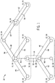
- a second internal network 40 includes the network devices 16, 20, 22, and 24. Within the internal network 40, the network device 16 may function as a router for the internal network 38. Moreover, a third internal network 42 includes the network devices 18 and 26. Within the internal network 42, the network device 18 may function as a router for the internal network 42. Furthermore, a fourth internal network 44 includes the network devices 22 and 28. Within the internal network 44, the network device 22 may function as a router for the internal network 44. A fifth internal network 46 includes the network devices 28, 30, 32, and 34. Within the internal network 46, the network device 28 may function as a router for the internal network 46.
- FIG. 4 is a block diagram of an embodiment of a network device 12 that may operate as a routing device (e.g., router).
- the network device 12 may include the one or more processors 86, the memory devices 88, and/or the storage devices 90.
- the network device 12 also includes the network interface device 92 for communicating with other devices on a network.
- the network device 12 includes additional network interface devices 94 and 96.
Landscapes
- Engineering & Computer Science (AREA)
- Computer Networks & Wireless Communication (AREA)
- Signal Processing (AREA)
- Computing Systems (AREA)
- Health & Medical Sciences (AREA)
- General Health & Medical Sciences (AREA)
- Medical Informatics (AREA)
- Computer Security & Cryptography (AREA)
- Small-Scale Networks (AREA)
- Data Exchanges In Wide-Area Networks (AREA)
- Arc Welding Control (AREA)
Description
- The invention relates generally to welding systems and, more specifically, to digital networking within a welding system.
- Welding-related devices, such as welding power supplies, welding wire feeders, welding torches, welding helmets, welding control pendants, welding foot pedals, and other electronic devices, are often electronically coupled together in a welding system. The welding-related devices may include network devices that are used to control the devices, and to facilitate communication between the devices. For example, network devices may enable certain devices in the welding system to communicate together using a network medium and a network protocol, such as Ethernet, universal serial bus (USB), and/or other serial communication architectures (e.g., RS-232, RS-422, etc.). Unfortunately, devices in the welding system that are on different networks may be unable to communicate together. Furthermore, certain communication architectures may be difficult to implement using certain network devices, such as embedded systems.
US 2003/0095548 A1 relates to a destination address retrieving system that generates a retrieval key from a header information of a packet and that performs a retrieval to an address information table based on the key and receives a returned value.
US 6,625,124 B1 relates to an automatic network topology identification technique. - The present invention relates to a method for handling a data packet as defined by independent claim 1, to a network device as defined by independent claim 9, and to a communication system for use in a welding system as defined by
independent claim 12, wherein further developments of the inventive method, the inventive network device, and the inventive communication system are defined by the sub-claims respectively. - In one embodiment, a method for handling a data packet includes receiving, at a network device, the data packet. The method also includes separating, by the network device, first network layer data of the data packet from message data of the data packet. The message data of the data packet includes a source address represented by less than four bytes, a destination address represented by less than four bytes, and a format identifier. The method includes determining whether the destination address of the message data matches an address of the network device or whether the message data indicates a broadcast message. The method also includes processing, by the network device, the format identifier if the destination address of the message data matches the address of the network device or if the message data indicates the broadcast message. The method includes providing, by the network device, the message data to the network device, one or more other network devices, or some combination thereof.
- In another embodiment, a network device includes a processing device configured to form message data. The message data includes a source address represented by less than four bytes, a destination address represented by less than four bytes, and a format identifier. The network device also includes a network interface device configured to receive the message data from the processing device, to combine the message data with network layer data to form a data packet, and to provide the data packet from the network device to one or more other network devices using one or more network media.
- In a further embodiment, a welding system includes a first network device configured to receive a first data packet and to separate first network layer data of the first data packet from message data of the first data packet. The message data of the first data packet includes a source address represented by less than four bytes, a destination address represented by less than four bytes, and a format identifier. The first network device is configured to determine whether the destination address of the message data matches an address of the network device or whether the message data indicates a broadcast message, to process the format identifier if the destination address of the message data matches the address of the first network device or if the message data indicates the broadcast message, and to package the message data in a second data packet with second network layer data. The welding system also includes a second network device configured to receive the second data packet if the destination address of the message data does not match the address of the first network device or if the message data indicates the broadcast message.
- These and other features, aspects, and advantages of the present invention will become better understood when the following detailed description is read with reference to the accompanying drawings in which like characters represent like parts throughout the drawings, wherein:
-
FIG. 1 is a diagram of an embodiment of a welding system that enables communication between network devices in different internal networks of the welding system, in accordance with embodiments of the present disclosure; -
FIG. 2 is a flow chart of an embodiment of a method for assigning addresses in a welding system having network devices in different internal networks, in accordance with embodiments of the present disclosure; -
FIG. 3 is a block diagram of an embodiment of a network device that may operate as a non-routing device, in accordance with embodiments of the present disclosure; -
FIG. 4 is a block diagram of an embodiment of a network device that may operate as a routing device, in accordance with embodiments of the present disclosure; -
FIG. 5 is a block diagram of an embodiment of message data that may be provided by one network device to another network device, in accordance with embodiments of the present disclosure; -
FIG. 6 is a block diagram of an embodiment of a message header of the message data ofFIG. 5 , in accordance with embodiments of the present disclosure; -
FIG. 7 is a block diagram of an embodiment of a message payload of the message data ofFIG. 5 , in accordance with embodiments of the present disclosure; -
FIG. 8 is a block diagram of an embodiment of a data packet which includes the message data ofFIG. 5 , in accordance with embodiments of the present disclosure; and -
FIG. 9 is a flow chart of an embodiment of a method for handling a data packet in a welding system having network devices in different internal networks, in accordance with embodiments of the present disclosure. - Turning to the drawings,
FIG. 1 is a diagram of an embodiment of awelding system 10 that enables communication betweennetwork devices 12 in different internal networks of thewelding system 10. As may be appreciated, eachnetwork device 12 may be an embedded system, such as a computer system with a dedicated function within thewelding system 10. In certain embodiments, one ormore network devices 12 may be sensors. Moreover, thenetwork devices 12 may be part of welding-related devices and may include a processor, electronic components, and/or control circuitry to control operation of various tasks. Eachnetwork device 12 may be part of separate welding-related devices and/or a welding-related device may include more than onenetwork device 12. As illustrated, thewelding system 10 includes network devices 14, 16, 18, 20, 22, 24, 26, 28, 30, 32, 34, and 36. All of thenetwork devices 12 may be disposed in one of a welding power supply, welding wire feeder, welding torches, welding helmets, welding control pendants, welding foot pedals, and so forth. - Each of the network devices 14, 16, 18, 20, 22, 24, 26, 28, 30, 32, 34, and 36 are part of one or more internal networks. Specifically, a first
internal network 38 includes the network devices 14, 16, and 18. Within theinternal network 38, the network device 14 may function as a router for theinternal network 38. As the router, the network device 14 controls routing of data to aparticular network device 12 within theinternal network 38. Moreover, the network device 14 may also function as a master device (e.g., root node) for thewelding system 10. As the master node, the network device 14 controls assignment of addresses to all of the network devices 14, 16, 18, 20, 22, 24, 26, 28, 30, 32, 34, and 36 of thewelding system 10. - A second
internal network 40 includes the network devices 16, 20, 22, and 24. Within theinternal network 40, the network device 16 may function as a router for theinternal network 38. Moreover, a thirdinternal network 42 includes the network devices 18 and 26. Within theinternal network 42, the network device 18 may function as a router for theinternal network 42. Furthermore, a fourthinternal network 44 includes the network devices 22 and 28. Within theinternal network 44, the network device 22 may function as a router for theinternal network 44. A fifthinternal network 46 includes the network devices 28, 30, 32, and 34. Within theinternal network 46, the network device 28 may function as a router for theinternal network 46. - As may be appreciated, the routers may function as bridging devices between different
internal networks internal networks internal networks network devices 12 of thewelding system 10 may communicate with anyother network device 12 of thewelding system 10. Theinternal networks - As illustrated,
network connections network connections internal networks internal networks welding system 10 may have any suitable number ofnetwork devices 12 and/or any number ofinternal networks -
FIG. 2 is a flow chart of an embodiment of amethod 68 for assigning addresses in thewelding system 10 havingnetwork devices 12 in differentinternal networks network device 12 may be assigned a unique system address for use in communicating within thewelding system 10. In certain embodiments, the address may be formed from approximately one byte of data. Accordingly, in such an embodiment, 256 different addresses may be assigned. As illustrated by themethod 68, anetwork device 12 sends an address request to a router of an internal network that thenetwork device 12 is part of (block 70). For example, the network device 30 illustrated inFIG. 1 may send an address request to the network device 28. In certain embodiments, thenetwork device 12 may broadcast an address request to all devices of the internal network. If the router is not the master device (e.g., the network device 14) of thewelding system 10 as determined byblock 72, themethod 68 returns to block 70 and the router sends the address request to a higher level router. For example, the network device 28 illustrated inFIG. 1 is not a master device of thewelding system 10, so the network device 28 sends the address request to the network device 22 (e.g., a higher level router). Moreover, the network device 22 is not a master device of thewelding system 10, so the network device 22 sends the address request to the network device 16. Furthermore, the network device 16 is not a master device of thewelding system 10, so the network device 16 sends the address request to the network device 14. As may be appreciated, each of the routers along the path from the network device 30 to the network device 14 may store a record of the path back to the network device 30 (e.g., the originating device). For example, if theinternal network 46 is an Ethernet network, the network device 28 may store data in a route table indicating a type of network medium (e.g., Ethernet) by which data was received from the network device 30 in conjunction with a media access control (MAC) address (or some other identifier) corresponding to the network device 30. - If the router is the master device of the welding system 10 (e.g., the network device 14), the master device assigns an address to the originating device (block 74). Moreover, the master device stores a record of the address assignment (block 76). For example, the network device 14 may store an address assignment for the network device 30 in conjunction with a MAC address corresponding to the network device 30. The master device provides the assigned address to the device that the master device received the request from (block 78). For example, the network device 14 provides the assigned address for the network device 30 to the network device 16. A determination is made concerning whether the originating device has received the assigned address (block 80).
- If the originating device has not received the assigned address, the
network device 12 stores the received address assignment in its routing table (block 82), then returns to block 78. For example, the network device 16 may store an address for the network device 30 that is received from the network device 16. Then, the network device 16 may provide the address to the network device 22, and so forth. If the originating device has received the assigned address, the originating device stores the address assignment (block 84). For example, the network device 30 stores its address assignment after it is received. Accordingly, unique addresses may be assigned tonetwork devices 12 in thewelding system 10. -
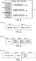
FIG. 3 is a block diagram of an embodiment of anetwork device 12 that may operate as a non-routing device (e.g., non-router). Thenetwork device 12 may include one ormore processors 86,memory devices 88, and/orstorage devices 90. The processor(s) 86 may be used to execute software, such as data processing, welding operation quality determination, welding control, and so forth. Moreover, the processor(s) 86 may include one or more microprocessors, such as one or more "general-purpose" microprocessors, one or more special-purpose microprocessors and/or application specific integrated circuits (ASICS), or some combination thereof. For example, the processor(s) 86 may include one or more reduced instruction set (RISC) processors. In certain embodiments, the processor(s) 86 may be used to form message data for messages sent from thenetwork device 12. - The storage device(s) 90 (e.g., nonvolatile storage) may include read-only memory (ROM), flash memory, a hard drive, or any other suitable optical, magnetic, or solid-state storage medium, or a combination thereof. The storage device(s) 90 may store data (e.g., welding data, address data, control data, message data, etc.), instructions (e.g., software or firmware for determining welding parameters, etc.), and any other suitable data.
- The memory device(s) 88 may include a volatile memory, such as random access memory (RAM), and/or a nonvolatile memory, such as ROM. The memory device(s) 88 may store a variety of information and may be used for various purposes. For example, the memory device(s) 88 may store processor-executable instructions (e.g., firmware or software) for the processor(s) 86 to execute, such as instructions for determining parameters of a welding operation.
- The
network device 12 also includes anetwork interface device 92 to enable thenetwork device 12 to communicate with other devices on a network. Thenetwork interface device 92 may enable communication over a specific network (e.g., theinternal networks network interface device 92 enables thenetwork device 12 to communicate withother network devices 12 that are part of thewelding system 10. Moreover, in certain embodiments, thenetwork interface device 92 may be configured to receive message data from the processor(s) 86, to combine the message data with network layer data to form a data packet, and to provide the data packet from thenetwork device 12 to asecond network device 12 using one or more network mediums. -
FIG. 4 is a block diagram of an embodiment of anetwork device 12 that may operate as a routing device (e.g., router). In the illustrated embodiment, thenetwork device 12 may include the one ormore processors 86, thememory devices 88, and/or thestorage devices 90. Thenetwork device 12 also includes thenetwork interface device 92 for communicating with other devices on a network. Moreover, thenetwork device 12 includes additionalnetwork interface devices network interface devices network device 12 to receive data from one network (e.g., theinternal networks network interface device 92, and to provide data to another network (e.g., theinternal networks network interface devices 94 and/or 96. Moreover, in some embodiments, the multiplenetwork interface devices network device 12 to route data within a single internal network, such as for routing to threedifferent network devices 12. -
FIG. 5 is a block diagram of an embodiment ofmessage data 98 that may be provided by onenetwork device 12 to anothernetwork device 12. As used herein, themessage data 98 may refer to feedback data, configuration data, data files, any payload, and/or any suitable information sent from one device to another. Themessage data 98 includes amessage header 100 and amessage payload 102. In certain embodiments, themessage header 100 may be provided and/or received first, followed by themessage payload 102. Moreover,FIG. 6 is a block diagram of an embodiment of themessage header 100 of themessage data 98 ofFIG. 5 . Themessage header 100 includes four different portions. Specifically, themessage header 100 includes atype 104, asource address 106, a target address 108 (e.g., destination address), and a format identifier 110 (e.g., send display data, get data, get configuration, etc.). In certain embodiments, thetype 104, thesource address 106, thetarget address 108, and theformat identifier 110 are each one byte such that themessage header 100 is four bytes total. Accordingly, with such amessage header 100, themessage data 98 may be scalable (e.g., having a changeable size) and/or tunnelable (e.g., encapsulated within another network protocol). In certain embodiments, any of thetype 104, thesource address 106, thetarget address 108, and theformat identifier 110 may be larger than one byte, yet still small enough to be scalable and/or tunnelable in certain networks. For example, in certain embodiments, thesource address 106 and/or thetarget address 108 may each be greater than one byte and less than four bytes. - The
type 104 may include a six bit tag, such as a wrapping counter used to represent a total number of messages sent from anetwork device 12. In certain embodiments, the wrapping counter may skip the value of zero. In such embodiments, the value of zero may identify a broadcast message, or a registered message. Moreover, in some embodiments, not all of the six bit tag may be used as part of the wrapping counter. For example, anetwork device 12 may choose to wrap 2, 3, 4, or 5 bits, and may use the remaining bits (e.g., high bits, low bits, etc.) to indicate an originating message source within the network device (e.g., a specific state machine or software module). In certain embodiments, responses to a command message having a specific six bit tag may include the same six bit tag in a response message header of the response. - Furthermore, the
type 104 may include a seventh bit used to indicate whether themessage data 98 is a command message or a response message. In certain embodiments, the seventh bit may also be used to indicate whether themessage data 98 is a broadcast message or a registered message. In such embodiments, the six bit tag may be zero to indicate that the seventh bit represents either a broadcast or a registered message. Accordingly, using the six bit tag and the seventh bit, four types of messages may be used. First, a direct command, which is an unsolicited message sent from a source address to a target address. Second, a direct response, which is a reply sent from a source address to a requesting target address. Third, a broadcast message, which is a message from a source address to all addresses. Fourth, a registered message, which is a message identified by a registered message index (e.g., an identification of the registered message of the sending network device 12). Moreover, thetype 104 may include an eighth bit used to indicate whether themessage data 98 is intended for thewelding system 10 as a whole or for a specificinternal network network device 12 to request an address. Moreover, a routing device may receive such an address request and forward the request to otherinternal networks - The
source address 106 may be represented by eight bits and may be a unique address that corresponds to anetwork device 12 within thewelding system 10 from which themessage data 98 originates. In certain embodiments, thesource address 106 may represent a registered message index, for a registered message based system. As may be appreciated, in a registered message based system, anetwork device 12 may request a registered message index from a master device before a registered message may be broadcast toother network devices 12. Thetarget address 108 may also be represented by eight bits and may be a unique address that corresponds to anetwork device 12 within thewelding system 10 for themessage data 98 to be sent to. In certain embodiments, thetarget address 108 may correspond to a group ofnetwork devices 12, such as for a broadcast message. Moreover, theformat identifier 110 may be represented by eight bits and may indicate a format of the data provided by thenetwork device 12 with thetarget address 108. - As may be appreciated, embodiments in which the
source address 106 and/or thetarget address 108 are a single byte, themessage header 100 may be smaller than in other embodiments in which thesource address 106 and/or thetarget address 108 are larger than one byte. Furthermore, thetype 104, thesource address 106, thetarget address 108, and theformat identifier 110 may be sent and/or received in any suitable order. Moreover, the routable addressing enables thenetwork devices 12 to share data withother network devices 12 without being aware of network protocols or physical communication media of theother network devices 12. Furthermore, thenetwork devices 12 communicate without knowing whether multiple internal networks are involved in the communication. -
FIG. 7 is a block diagram of an embodiment of themessage payload 102 of themessage data 98 ofFIG. 5 . Themessage payload 102 includespayload data 112, a token 114,token data 116, and/oradditional data 118. Specifically, thepayload data 112 includes data that corresponds to theformat identifier 110. As may be appreciated, thepayload data 112 may include other identifiers (e.g., identifiers in addition to the format identifier 110) to be performed by thenetwork device 12. In certain embodiments, the token 114 may be an item from a token list. The token list is a list of token values (e.g., unique numbers) that identify variables that may be read from or written to anetwork device 12. For example, a token value of six may represent a preset welding voltage. Moreover, in certain embodiments, an engineering unit may be part of the token list and may identify an engineering unit that corresponds to the token value, thereby reducing an amount oftoken data 116 communicated betweennetwork devices 12. Thetoken data 116 may include any suitable data that corresponds to thetoken 114. For example, thetoken data 116 may include a symbol from a symbol list, an engineering unit from an engineering unit list, and/or any other data from a list. Moreover, the symbol list may include a list of unique numbers identifying specific concepts, list items, text words, and/or phrases that may not be represented using a single number. For example, a symbol six may represent "off" and a symbol twenty-three may represent "on." Furthermore, the engineering unit list may be a list (e.g., or a subset of the symbol list) that identifies engineering units and scales that binary values may be stored in. For example, a "0.1 Volt" engineering unit may represent 1.0 volts as 10 in binary data. Moreover, any number oftokens 114 andtoken data 116 may be included as represented by theadditional data 118. As may be appreciated, themessage payload 102 may be any suitable size enabled by a network transport layer. -
FIG. 8 is a block diagram of an embodiment of adata packet 120 which includes themessage data 98 ofFIG. 5 . As illustrated, thedata packet 120 includes networklayer header data 122 and themessage data 98. In certain embodiments, thedata packet 120 also includes networklayer footer data 124. The networklayer header data 122 and/or the networklayer footer data 124 is packaged with themessage data 98 by thenetwork device 12 before thenetwork device 12 provides thedata packet 120 to anothernetwork device 12 in the welding system 10 (e.g., using one of thenetwork interface devices message data 98. In certain embodiments, the networklayer header data 122 and/or the networklayer footer data 124 may include a MAC address of the source network device 12 (e.g., thenetwork device 12 sending the message) and a MAC address of a destination network device 12 (e.g., thenext network device 12 to receive the message). As may be appreciated, the MAC address of thedestination network device 12 may not necessarily be the MAC address of thenetwork device 12 having thetarget address 108 because themessage data 98 may get routed through differentinternal networks network device 12 having thetarget address 108. The networklayer header data 122 and/or the networklayer footer data 124 is used to move themessage data 98 within a network toward thenetwork device 12 having the target address. -
FIG. 9 is a flow chart of an embodiment of amethod 126 for handling thedata packet 120 in thewelding system 10 having thenetwork devices 12 in differentinternal networks network device 12 receives the data packet 120 (block 128). Thenetwork device 12 separates network layer data (e.g., the networklayer header data 122 and/or the network layer footer data 124) from the message data 98 (block 130). In certain embodiments, the network layer data includes a destination MAC address corresponding to thenetwork device 12. Thenetwork device 12 determines whether the target address 108 (e.g., destination address) of themessage data 98 matches an address of the network device 12 (block 132). If thetarget address 108 matches the address of thenetwork device 12, thenetwork device 12 processes theformat identifier 110 of the message data 98 (block 134). - However, if the
target address 108 does not match the address of thenetwork device 12, thenetwork device 12 packs new network layer data with thesame message data 98 it received (block 136). In certain embodiments, the new network layer data includes a source MAC address corresponding to thenetwork device 12. Thenetwork device 12 then provides thedata packet 120 to asecond network device 12 via a network medium (block 138). As may be appreciated, the new network layer data may include a destination MAC address corresponding to thesecond network device 12. Furthermore, in certain embodiments, thesecond network device 12 may be a router. Themethod 126 then returns to block 128. - By using the methods and systems described herein, messages may be communicated between
network devices 12 within awelding system 10. The messages may be provided by onenetwork device 12 and may be communicated through one or moreinternal networks destination network device 12. The addresses used within thewelding system 10 may be single-byte addresses, thereby facilitating a low amount of header data for transmitted messages. Furthermore, the messages may be received by anetwork device 12 exactly as the message was sent from anothernetwork device 12. - While only certain features of the invention have been illustrated and described herein, many modifications and changes will occur to those skilled in the art.
Claims (15)
- A method for handling a data packet (120), comprising:- receiving, at a network device (12), the data packet (120);- separating, by the network device (12), first network layer data of the data packet (120) from message data (98) of the data packet (120), wherein the message data (98) of the data packet (120) comprises a message header (100), the message header (100) comprising:- a message type (104) comprising a wrapping counter used to represent a total number of messages sent by an originating network device (12) and/ or one or two message type indicators indicating whether the message is a broadcast message;- a source address (106) represented by less than four bytes;- a destination address (108) represented by less than four bytes; and- a format identifier (110) indicative of a format of payload data (112) of the message data (98);- determining whether the destination address (108) of the message data (98) matches an address of the network, device (12) and/or whether the one or two message type indicators indicate that the message is a broadcast message;- processing, by the network device (12), the format identifier (110) if the destination address (108) of the message data (98) matches the address of the network device (12) or if the message data (98) indicates the broadcast message and else, if the destination address does not match, providing, by the network device (12), the message data (98) to one or more other network devices (12).
- The method of claim 1,
wherein receiving the data packet (120) comprises receiving the data packet (120) via an Ethernet interface, a serial interface, or a universal serial bus (USB) interface. - The method of claim 1 or 2,
wherein the source address (106) comprises only one byte, and/ or wherein the destination address (108) comprises only one byte. - The method of one of claims 1 to 3,
wherein the message data (98) comprises a message header (100) and a message body (102), wherein the message body comprises the payload data (112), one or more tokens (114), or some combination thereof. - The method of one of the preceding claims,
wherein the message header (100) consists of four bytes. - The method of one of the preceding claims,
wherein the first network layer data comprises a media access control (MAC) address corresponding to the network device (12). - The method of one of the preceding claims,
wherein providing the message data (98) to one or more other network devices (12) thereof comprises packaging the message data (98) with second network layer data. - The method of claim 7,
wherein the second network layer data comprises a first MAC address corresponding to the network device (12) and a second MAC address corresponding to one or more other network device (12)s. - A network device (12) comprising:- a processing device (86) configured to form message data (98); and- a network interface device (92, 94, 96) configured to receive the message data (98) from the processing device (86), to combine the message data (98) with network layer data to form a data packet (120), and to provide the data packet (120) from the network device (12) to one or more other network devices (12) using one or more network media,characterized in that
the message data (98) comprise a message header (100), the message header (100) comprising:- a message type (104) comprising a wrapping counter used to represent a total number of messages sent by an originating network device (12) and/ or one or two message type indicators indicating whether the message is a broadcast message;- a source address (106) represented by less than four bytes;- a destination address (108) represented by less than four bytes; and- a format identifier (110) indicative of a format of payload data (112) of the message data (98),wherein the network device (12) is configured to- determine whether the destination address (108) of the message data (98) matches an address of the network device (12) and/or whether the one or two message type indicators indicate that the message is a broadcast message; and- process the format identifier (110) if the destination address (108) of the message data (98) matches the address of the network device (12) or if the message data (98) indicates the broadcast message and else, if the destination address does not match, to provide the message data (98) to one or more other network devices (12). - The network device (12) of claim 9,
wherein the message data (98) comprises a message header (100) and a message body (102), and wherein the message header (100) consists of four bytes. - The network device (12) of claim 9 or 10,
wherein the network interface device (92, 94, 96) comprises one or more of an Ethernet interface, a serial interface, and a USB interface. - A communication system for use in a welding system, comprising:- a first network device (12) as defined in one of claims 9 to 11, further confgured to package the message data (98) in a second data packet (120) with second network layer data; and- a second network device (12) configured to receive the second data packet (120) if the destination address (108) of the message data (98) does not match the address of the first network device (12) or if the message data (98) indicates the broadcast message.
- The system of claim 12,
comprising a first network medium to provide the first data packet (120) to the first network device (12) and a second network medium to provide the second data packet (120) from the first network device (12) to the second network device (12). - The system of claim 13,
wherein the first network medium and the second network medium comprise an Ethernet interface, and/ or
wherein the first network medium and the second network medium comprise different network media. - The system of one of claims 12 to 14,
wherein the source address (106) corresponds to a third network device (12) that is not the first network device (12) or the second network device (12), the destination address (108) corresponds to a fourth network device (12) that is not the first network device (12) or the second network device (12), or some combination thereof.
Applications Claiming Priority (2)
| Application Number | Priority Date | Filing Date | Title |
|---|---|---|---|
| US14/022,311 US10270719B2 (en) | 2013-09-10 | 2013-09-10 | Methods for handling data packets in a digital network of a welding system |
| PCT/US2014/047497 WO2015038239A1 (en) | 2013-09-10 | 2014-07-21 | Digital networking in a welding system |
Publications (2)
| Publication Number | Publication Date |
|---|---|
| EP3044940A1 EP3044940A1 (en) | 2016-07-20 |
| EP3044940B1 true EP3044940B1 (en) | 2018-11-28 |
Family
ID=51299019
Family Applications (1)
| Application Number | Title | Priority Date | Filing Date |
|---|---|---|---|
| EP14748414.1A Active EP3044940B1 (en) | 2013-09-10 | 2014-07-21 | Digital networking in a welding system |
Country Status (8)
| Country | Link |
|---|---|
| US (2) | US10270719B2 (en) |
| EP (1) | EP3044940B1 (en) |
| JP (1) | JP2016539586A (en) |
| KR (1) | KR102179982B1 (en) |
| CN (1) | CN105519081B (en) |
| CA (1) | CA2918372C (en) |
| MX (1) | MX358232B (en) |
| WO (1) | WO2015038239A1 (en) |
Families Citing this family (2)
| Publication number | Priority date | Publication date | Assignee | Title |
|---|---|---|---|---|
| CN218891307U (en) | 2020-01-13 | 2023-04-21 | 米沃奇电动工具公司 | Portable welding machine powered by battery pack |
| KR20230115074A (en) * | 2022-01-26 | 2023-08-02 | 주식회사 엘지에너지솔루션 | Battery management system and operating method of the same |
Citations (1)
| Publication number | Priority date | Publication date | Assignee | Title |
|---|---|---|---|---|
| US7026929B1 (en) * | 2002-05-10 | 2006-04-11 | A La Cart, Inc. | Food information monitoring system |
Family Cites Families (34)
| Publication number | Priority date | Publication date | Assignee | Title |
|---|---|---|---|---|
| US4422171A (en) * | 1980-12-29 | 1983-12-20 | Allied Corporation, Law Department | Method and system for data communication |
| WO1997009804A1 (en) * | 1995-09-06 | 1997-03-13 | Fujitsu Limited | Exchange for controlling communication service |
| US6006254A (en) * | 1997-08-29 | 1999-12-21 | Mitsubishi Electric Information Technology Center America, Inc. | System for the reliable, fast, low-latency communication of object state updates over a computer network by combining lossy and lossless communications |
| US6498787B1 (en) * | 1998-12-30 | 2002-12-24 | Motorola, Inc. | Method and apparatus for sending and receiving service utilization messages |
| US6956852B1 (en) * | 1999-06-25 | 2005-10-18 | Cisco Technology Inc. | Multi-function high-speed network interface |
| US6625124B1 (en) * | 2000-03-03 | 2003-09-23 | Luminous Networks, Inc. | Automatic reconfiguration of short addresses for devices in a network due to change in network topology |
| AT411312B (en) * | 2000-10-20 | 2003-11-25 | Universal Comm Platform Ag | METHOD FOR TRANSMITTING SHORT MESSAGES (SMS) BETWEEN COMPUTERS ON THE INTERNET |
| US7882253B2 (en) * | 2001-04-05 | 2011-02-01 | Real-Time Innovations, Inc. | Real-time publish-subscribe system |
| JP3627697B2 (en) * | 2001-11-16 | 2005-03-09 | 日本電気株式会社 | Packet destination search system |
| US7873028B2 (en) * | 2002-01-25 | 2011-01-18 | Quanta Computer, Inc. | Method and apparatus for a flexible peripheral access router |
| US8018932B1 (en) * | 2002-06-28 | 2011-09-13 | Cisco Technology, Inc. | Methods and apparatus for sending a multicast packet from multiple network interfaces using the same MAC source address |
| US8245032B2 (en) * | 2003-03-27 | 2012-08-14 | Avaya Inc. | Method to authenticate packet payloads |
| DE60320773D1 (en) * | 2003-06-30 | 2008-06-19 | Research In Motion Ltd | Processing Commands for a Radio Modem During Data Connections |
| US7668143B2 (en) * | 2003-07-30 | 2010-02-23 | Nippon Telegraph And Telephone Corporation | Wireless packet communication method and apparatus |
| US20050220096A1 (en) | 2004-04-06 | 2005-10-06 | Robert Friskney | Traffic engineering in frame-based carrier networks |
| GB2415855B (en) | 2004-07-02 | 2007-09-19 | Toshiba Res Europ Ltd | Communications apparatus providing local addressing |
| KR100606005B1 (en) * | 2004-09-23 | 2006-07-28 | 삼성전자주식회사 | How to manage IP address for IPC |
| US20060072594A1 (en) * | 2004-10-04 | 2006-04-06 | Vikram Swamy | Gaming environment including a virtual network |
| BRPI0519612A2 (en) * | 2004-12-31 | 2009-02-25 | British Telecomm | switching apparatus in a communications network, methods of modifying switching apparatus positioned in a communications network, of switching packets via a communications network comprising a plurality of interconnected switching apparatus, of generating an end-to-end connection via a communications network comprising a plurality of switching apparatus preconfigured to support a connectionless communications protocol, to provide differentiated routing modes for packetized data, to configure switching apparatus to receive management and/or signaling information, network of communications, control plane processor, and, communication scheme to configure a network |
| US9687931B2 (en) * | 2006-12-05 | 2017-06-27 | Lincoln Global, Inc. | System for measuring energy using digitally controlled welding power sources |
| KR100754649B1 (en) | 2006-07-24 | 2007-09-05 | 삼성전자주식회사 | Bridge-based wireless base station backbone network system and signal processing method |
| US20080140815A1 (en) | 2006-12-12 | 2008-06-12 | The Lincoln Electric Company | Network Device Location and Configuration |
| WO2009127961A1 (en) * | 2008-04-16 | 2009-10-22 | Nokia Corporation | Decoding order recovery in session multiplexing |
| US9069727B2 (en) * | 2011-08-12 | 2015-06-30 | Talari Networks Incorporated | Adaptive private network with geographically redundant network control nodes |
| KR101165642B1 (en) * | 2009-09-02 | 2012-07-16 | 엘지전자 주식회사 | Method and Apparatus of transmitting and receiving MAC PDU using a MAC header |
| US20110240620A1 (en) * | 2010-04-05 | 2011-10-06 | Illinois Tool Works Inc. | Welding system and method utilizing internal ethernet communications |
| US20120097644A1 (en) * | 2010-10-26 | 2012-04-26 | Illinois Tool Works Inc. | Modular data over power converter for welding power supply |
| US8730912B2 (en) * | 2010-12-01 | 2014-05-20 | Qualcomm Incorporated | Determining a non-access stratum message count in handover |
| US9071629B2 (en) * | 2011-01-07 | 2015-06-30 | Jeda Networks, Inc. | Methods for the interconnection of fibre channel over ethernet devices using shortest path bridging |
| US8788139B2 (en) * | 2011-03-21 | 2014-07-22 | Webtech Wireless Inc. | Multi-protocol vehicle diagnostic interface device and method |
| US20130288211A1 (en) * | 2012-04-27 | 2013-10-31 | Illinois Tool Works Inc. | Systems and methods for training a welding operator |
| DE102012023395A1 (en) * | 2012-11-29 | 2014-06-05 | Eads Deutschland Gmbh | Interface device and method for exchanging user data |
| US9350558B2 (en) * | 2013-01-09 | 2016-05-24 | Dell Products L.P. | Systems and methods for providing multicast routing in an overlay network |
| US9426261B2 (en) * | 2013-05-15 | 2016-08-23 | Qualcomm Incorporated | Apparatus and methods for improved frames |
-
2013
- 2013-09-10 US US14/022,311 patent/US10270719B2/en active Active
-
2014
- 2014-07-21 EP EP14748414.1A patent/EP3044940B1/en active Active
- 2014-07-21 KR KR1020167005817A patent/KR102179982B1/en not_active Expired - Fee Related
- 2014-07-21 CN CN201480049356.2A patent/CN105519081B/en not_active Expired - Fee Related
- 2014-07-21 WO PCT/US2014/047497 patent/WO2015038239A1/en not_active Ceased
- 2014-07-21 JP JP2016541964A patent/JP2016539586A/en not_active Withdrawn
- 2014-07-21 MX MX2016000541A patent/MX358232B/en active IP Right Grant
- 2014-07-21 CA CA2918372A patent/CA2918372C/en not_active Expired - Fee Related
-
2019
- 2019-02-28 US US16/289,343 patent/US11343211B2/en active Active
Patent Citations (1)
| Publication number | Priority date | Publication date | Assignee | Title |
|---|---|---|---|---|
| US7026929B1 (en) * | 2002-05-10 | 2006-04-11 | A La Cart, Inc. | Food information monitoring system |
Also Published As
| Publication number | Publication date |
|---|---|
| JP2016539586A (en) | 2016-12-15 |
| CA2918372C (en) | 2020-06-16 |
| MX358232B (en) | 2018-08-10 |
| US20190199662A1 (en) | 2019-06-27 |
| EP3044940A1 (en) | 2016-07-20 |
| MX2016000541A (en) | 2016-04-11 |
| CA2918372A1 (en) | 2015-03-19 |
| KR20160054473A (en) | 2016-05-16 |
| CN105519081A (en) | 2016-04-20 |
| US20150074190A1 (en) | 2015-03-12 |
| WO2015038239A1 (en) | 2015-03-19 |
| CN105519081B (en) | 2019-10-15 |
| US10270719B2 (en) | 2019-04-23 |
| US11343211B2 (en) | 2022-05-24 |
| KR102179982B1 (en) | 2020-11-17 |
Similar Documents
| Publication | Publication Date | Title |
|---|---|---|
| EP3958521B1 (en) | Method and apparatus for providing service for service flow | |
| CN109688057B (en) | Message forwarding method and device of segment routing network based on IPV6 | |
| CN108737269B (en) | Encapsulation method, device and node | |
| US10382309B2 (en) | Method and apparatus for tracing paths in service function chains | |
| CN107547508B (en) | Message sending and receiving method, device and network equipment | |
| EP3282649B1 (en) | Data packet forwarding | |
| WO2016131225A1 (en) | Message forward processing method, apparatus, controller and routing forward device | |
| CN109412927B (en) | Multi-VPN data transmission method and device and network equipment | |
| US9985892B1 (en) | System and method for providing congestion notification in layer 3 networks | |
| CN105577545A (en) | Label-switched packets with device-independent labels | |
| CN113179189B (en) | Segment routing fault detection method, device, first segment routing and destination routing | |
| CN102035736A (en) | Forwarding apparatus and method of packets | |
| US11343211B2 (en) | Digital networking in a welding system | |
| CN104348728B (en) | Generate the method and apparatus of forwarding information | |
| WO2021227746A1 (en) | Packet transmission and forwarding methods, header node, forwarding node, and storage medium | |
| CN107733765B (en) | Mapping method, system and related equipment | |
| CN110661713A (en) | Message forwarding method and device | |
| CN104821914B (en) | The message forwarding method and equipment of across transparent interconnection of lots of links connection TRILL networks | |
| CN104967564B (en) | From VLAN to the message forwarding method of TRILL network and equipment | |
| CN116827860A (en) | An SRv6 message transmission method, device, node and storage medium | |
| CN108259350A (en) | A kind of message transmitting method, device and machine readable storage medium | |
| CN111211978B (en) | Method and device for distributing expanded segment routing labels | |
| CN103780468A (en) | Method enabling smart terminal to be accessed to TRILL network, smart terminal and route network bridge | |
| CN116264589A (en) | A message transmission method and device | |
| CN113765794B (en) | Data transmission method and device, electronic equipment and medium |
Legal Events
| Date | Code | Title | Description |
|---|---|---|---|
| PUAI | Public reference made under article 153(3) epc to a published international application that has entered the european phase |
Free format text: ORIGINAL CODE: 0009012 |
|
| 17P | Request for examination filed |
Effective date: 20160201 |
|
| AK | Designated contracting states |
Kind code of ref document: A1 Designated state(s): AL AT BE BG CH CY CZ DE DK EE ES FI FR GB GR HR HU IE IS IT LI LT LU LV MC MK MT NL NO PL PT RO RS SE SI SK SM TR |
|
| AX | Request for extension of the european patent |
Extension state: BA ME |
|
| DAX | Request for extension of the european patent (deleted) | ||
| STAA | Information on the status of an ep patent application or granted ep patent |
Free format text: STATUS: EXAMINATION IS IN PROGRESS |
|
| 17Q | First examination report despatched |
Effective date: 20170717 |
|
| REG | Reference to a national code |
Ref country code: DE Ref legal event code: R079 Ref document number: 602014036956 Country of ref document: DE Free format text: PREVIOUS MAIN CLASS: H04L0029120000 Ipc: H04L0012580000 |
|
| GRAP | Despatch of communication of intention to grant a patent |
Free format text: ORIGINAL CODE: EPIDOSNIGR1 |
|
| STAA | Information on the status of an ep patent application or granted ep patent |
Free format text: STATUS: GRANT OF PATENT IS INTENDED |
|
| RIC1 | Information provided on ipc code assigned before grant |
Ipc: H04L 12/58 20060101AFI20180626BHEP Ipc: H04L 29/08 20060101ALI20180626BHEP Ipc: H04L 29/12 20060101ALI20180626BHEP |
|
| INTG | Intention to grant announced |
Effective date: 20180720 |
|
| GRAS | Grant fee paid |
Free format text: ORIGINAL CODE: EPIDOSNIGR3 |
|
| GRAA | (expected) grant |
Free format text: ORIGINAL CODE: 0009210 |
|
| STAA | Information on the status of an ep patent application or granted ep patent |
Free format text: STATUS: THE PATENT HAS BEEN GRANTED |
|
| AK | Designated contracting states |
Kind code of ref document: B1 Designated state(s): AL AT BE BG CH CY CZ DE DK EE ES FI FR GB GR HR HU IE IS IT LI LT LU LV MC MK MT NL NO PL PT RO RS SE SI SK SM TR |
|
| REG | Reference to a national code |
Ref country code: CH Ref legal event code: EP |
|
| REG | Reference to a national code |
Ref country code: AT Ref legal event code: REF Ref document number: 1071562 Country of ref document: AT Kind code of ref document: T Effective date: 20181215 |
|
| REG | Reference to a national code |
Ref country code: DE Ref legal event code: R096 Ref document number: 602014036956 Country of ref document: DE |
|
| REG | Reference to a national code |
Ref country code: IE Ref legal event code: FG4D |
|
| REG | Reference to a national code |
Ref country code: NL Ref legal event code: MP Effective date: 20181128 |
|
| REG | Reference to a national code |
Ref country code: LT Ref legal event code: MG4D |
|
| REG | Reference to a national code |
Ref country code: AT Ref legal event code: MK05 Ref document number: 1071562 Country of ref document: AT Kind code of ref document: T Effective date: 20181128 |
|
| PG25 | Lapsed in a contracting state [announced via postgrant information from national office to epo] |
Ref country code: ES Free format text: LAPSE BECAUSE OF FAILURE TO SUBMIT A TRANSLATION OF THE DESCRIPTION OR TO PAY THE FEE WITHIN THE PRESCRIBED TIME-LIMIT Effective date: 20181128 Ref country code: BG Free format text: LAPSE BECAUSE OF FAILURE TO SUBMIT A TRANSLATION OF THE DESCRIPTION OR TO PAY THE FEE WITHIN THE PRESCRIBED TIME-LIMIT Effective date: 20190228 Ref country code: LT Free format text: LAPSE BECAUSE OF FAILURE TO SUBMIT A TRANSLATION OF THE DESCRIPTION OR TO PAY THE FEE WITHIN THE PRESCRIBED TIME-LIMIT Effective date: 20181128 Ref country code: HR Free format text: LAPSE BECAUSE OF FAILURE TO SUBMIT A TRANSLATION OF THE DESCRIPTION OR TO PAY THE FEE WITHIN THE PRESCRIBED TIME-LIMIT Effective date: 20181128 Ref country code: IS Free format text: LAPSE BECAUSE OF FAILURE TO SUBMIT A TRANSLATION OF THE DESCRIPTION OR TO PAY THE FEE WITHIN THE PRESCRIBED TIME-LIMIT Effective date: 20190328 Ref country code: NO Free format text: LAPSE BECAUSE OF FAILURE TO SUBMIT A TRANSLATION OF THE DESCRIPTION OR TO PAY THE FEE WITHIN THE PRESCRIBED TIME-LIMIT Effective date: 20190228 Ref country code: LV Free format text: LAPSE BECAUSE OF FAILURE TO SUBMIT A TRANSLATION OF THE DESCRIPTION OR TO PAY THE FEE WITHIN THE PRESCRIBED TIME-LIMIT Effective date: 20181128 Ref country code: AT Free format text: LAPSE BECAUSE OF FAILURE TO SUBMIT A TRANSLATION OF THE DESCRIPTION OR TO PAY THE FEE WITHIN THE PRESCRIBED TIME-LIMIT Effective date: 20181128 Ref country code: FI Free format text: LAPSE BECAUSE OF FAILURE TO SUBMIT A TRANSLATION OF THE DESCRIPTION OR TO PAY THE FEE WITHIN THE PRESCRIBED TIME-LIMIT Effective date: 20181128 |
|
| PG25 | Lapsed in a contracting state [announced via postgrant information from national office to epo] |
Ref country code: SE Free format text: LAPSE BECAUSE OF FAILURE TO SUBMIT A TRANSLATION OF THE DESCRIPTION OR TO PAY THE FEE WITHIN THE PRESCRIBED TIME-LIMIT Effective date: 20181128 Ref country code: AL Free format text: LAPSE BECAUSE OF FAILURE TO SUBMIT A TRANSLATION OF THE DESCRIPTION OR TO PAY THE FEE WITHIN THE PRESCRIBED TIME-LIMIT Effective date: 20181128 Ref country code: GR Free format text: LAPSE BECAUSE OF FAILURE TO SUBMIT A TRANSLATION OF THE DESCRIPTION OR TO PAY THE FEE WITHIN THE PRESCRIBED TIME-LIMIT Effective date: 20190301 Ref country code: RS Free format text: LAPSE BECAUSE OF FAILURE TO SUBMIT A TRANSLATION OF THE DESCRIPTION OR TO PAY THE FEE WITHIN THE PRESCRIBED TIME-LIMIT Effective date: 20181128 Ref country code: PT Free format text: LAPSE BECAUSE OF FAILURE TO SUBMIT A TRANSLATION OF THE DESCRIPTION OR TO PAY THE FEE WITHIN THE PRESCRIBED TIME-LIMIT Effective date: 20190328 |
|
| PG25 | Lapsed in a contracting state [announced via postgrant information from national office to epo] |
Ref country code: NL Free format text: LAPSE BECAUSE OF FAILURE TO SUBMIT A TRANSLATION OF THE DESCRIPTION OR TO PAY THE FEE WITHIN THE PRESCRIBED TIME-LIMIT Effective date: 20181128 |
|
| PG25 | Lapsed in a contracting state [announced via postgrant information from national office to epo] |
Ref country code: IT Free format text: LAPSE BECAUSE OF FAILURE TO SUBMIT A TRANSLATION OF THE DESCRIPTION OR TO PAY THE FEE WITHIN THE PRESCRIBED TIME-LIMIT Effective date: 20181128 Ref country code: DK Free format text: LAPSE BECAUSE OF FAILURE TO SUBMIT A TRANSLATION OF THE DESCRIPTION OR TO PAY THE FEE WITHIN THE PRESCRIBED TIME-LIMIT Effective date: 20181128 Ref country code: CZ Free format text: LAPSE BECAUSE OF FAILURE TO SUBMIT A TRANSLATION OF THE DESCRIPTION OR TO PAY THE FEE WITHIN THE PRESCRIBED TIME-LIMIT Effective date: 20181128 Ref country code: PL Free format text: LAPSE BECAUSE OF FAILURE TO SUBMIT A TRANSLATION OF THE DESCRIPTION OR TO PAY THE FEE WITHIN THE PRESCRIBED TIME-LIMIT Effective date: 20181128 |
|
| REG | Reference to a national code |
Ref country code: DE Ref legal event code: R097 Ref document number: 602014036956 Country of ref document: DE |
|
| PG25 | Lapsed in a contracting state [announced via postgrant information from national office to epo] |
Ref country code: RO Free format text: LAPSE BECAUSE OF FAILURE TO SUBMIT A TRANSLATION OF THE DESCRIPTION OR TO PAY THE FEE WITHIN THE PRESCRIBED TIME-LIMIT Effective date: 20181128 Ref country code: SK Free format text: LAPSE BECAUSE OF FAILURE TO SUBMIT A TRANSLATION OF THE DESCRIPTION OR TO PAY THE FEE WITHIN THE PRESCRIBED TIME-LIMIT Effective date: 20181128 Ref country code: EE Free format text: LAPSE BECAUSE OF FAILURE TO SUBMIT A TRANSLATION OF THE DESCRIPTION OR TO PAY THE FEE WITHIN THE PRESCRIBED TIME-LIMIT Effective date: 20181128 Ref country code: SM Free format text: LAPSE BECAUSE OF FAILURE TO SUBMIT A TRANSLATION OF THE DESCRIPTION OR TO PAY THE FEE WITHIN THE PRESCRIBED TIME-LIMIT Effective date: 20181128 |
|
| PLBE | No opposition filed within time limit |
Free format text: ORIGINAL CODE: 0009261 |
|
| STAA | Information on the status of an ep patent application or granted ep patent |
Free format text: STATUS: NO OPPOSITION FILED WITHIN TIME LIMIT |
|
| PG25 | Lapsed in a contracting state [announced via postgrant information from national office to epo] |
Ref country code: SI Free format text: LAPSE BECAUSE OF FAILURE TO SUBMIT A TRANSLATION OF THE DESCRIPTION OR TO PAY THE FEE WITHIN THE PRESCRIBED TIME-LIMIT Effective date: 20181128 |
|
| 26N | No opposition filed |
Effective date: 20190829 |
|
| PG25 | Lapsed in a contracting state [announced via postgrant information from national office to epo] |
Ref country code: IT Free format text: LAPSE BECAUSE OF FAILURE TO SUBMIT A TRANSLATION OF THE DESCRIPTION OR TO PAY THE FEE WITHIN THE PRESCRIBED TIME-LIMIT Effective date: 20181128 Ref country code: MC Free format text: LAPSE BECAUSE OF FAILURE TO SUBMIT A TRANSLATION OF THE DESCRIPTION OR TO PAY THE FEE WITHIN THE PRESCRIBED TIME-LIMIT Effective date: 20181128 |
|
| PGRI | Patent reinstated in contracting state [announced from national office to epo] |
Ref country code: IT Effective date: 20191022 |
|
| REG | Reference to a national code |
Ref country code: CH Ref legal event code: PL |
|
| GBPC | Gb: european patent ceased through non-payment of renewal fee |
Effective date: 20190721 |
|
| PG25 | Lapsed in a contracting state [announced via postgrant information from national office to epo] |
Ref country code: TR Free format text: LAPSE BECAUSE OF FAILURE TO SUBMIT A TRANSLATION OF THE DESCRIPTION OR TO PAY THE FEE WITHIN THE PRESCRIBED TIME-LIMIT Effective date: 20181128 |
|
| REG | Reference to a national code |
Ref country code: BE Ref legal event code: MM Effective date: 20190731 |
|
| PG25 | Lapsed in a contracting state [announced via postgrant information from national office to epo] |
Ref country code: GB Free format text: LAPSE BECAUSE OF NON-PAYMENT OF DUE FEES Effective date: 20190721 |
|
| PG25 | Lapsed in a contracting state [announced via postgrant information from national office to epo] |
Ref country code: LU Free format text: LAPSE BECAUSE OF NON-PAYMENT OF DUE FEES Effective date: 20190721 Ref country code: CH Free format text: LAPSE BECAUSE OF NON-PAYMENT OF DUE FEES Effective date: 20190731 Ref country code: BE Free format text: LAPSE BECAUSE OF NON-PAYMENT OF DUE FEES Effective date: 20190731 Ref country code: LI Free format text: LAPSE BECAUSE OF NON-PAYMENT OF DUE FEES Effective date: 20190731 |
|
| PG25 | Lapsed in a contracting state [announced via postgrant information from national office to epo] |
Ref country code: IE Free format text: LAPSE BECAUSE OF NON-PAYMENT OF DUE FEES Effective date: 20190721 |
|
| PGFP | Annual fee paid to national office [announced via postgrant information from national office to epo] |
Ref country code: FR Payment date: 20200727 Year of fee payment: 7 |
|
| PG25 | Lapsed in a contracting state [announced via postgrant information from national office to epo] |
Ref country code: CY Free format text: LAPSE BECAUSE OF FAILURE TO SUBMIT A TRANSLATION OF THE DESCRIPTION OR TO PAY THE FEE WITHIN THE PRESCRIBED TIME-LIMIT Effective date: 20181128 |
|
| PG25 | Lapsed in a contracting state [announced via postgrant information from national office to epo] |
Ref country code: MT Free format text: LAPSE BECAUSE OF FAILURE TO SUBMIT A TRANSLATION OF THE DESCRIPTION OR TO PAY THE FEE WITHIN THE PRESCRIBED TIME-LIMIT Effective date: 20181128 Ref country code: HU Free format text: LAPSE BECAUSE OF FAILURE TO SUBMIT A TRANSLATION OF THE DESCRIPTION OR TO PAY THE FEE WITHIN THE PRESCRIBED TIME-LIMIT; INVALID AB INITIO Effective date: 20140721 |
|
| REG | Reference to a national code |
Ref country code: DE Ref legal event code: R079 Ref document number: 602014036956 Country of ref document: DE Free format text: PREVIOUS MAIN CLASS: H04L0012580000 Ipc: H04L0051000000 |
|
| PG25 | Lapsed in a contracting state [announced via postgrant information from national office to epo] |
Ref country code: FR Free format text: LAPSE BECAUSE OF NON-PAYMENT OF DUE FEES Effective date: 20210731 |
|
| PG25 | Lapsed in a contracting state [announced via postgrant information from national office to epo] |
Ref country code: MK Free format text: LAPSE BECAUSE OF FAILURE TO SUBMIT A TRANSLATION OF THE DESCRIPTION OR TO PAY THE FEE WITHIN THE PRESCRIBED TIME-LIMIT Effective date: 20181128 |
|
| P01 | Opt-out of the competence of the unified patent court (upc) registered |
Effective date: 20230606 |
|
| PGFP | Annual fee paid to national office [announced via postgrant information from national office to epo] |
Ref country code: DE Payment date: 20250729 Year of fee payment: 12 |
|
| PGFP | Annual fee paid to national office [announced via postgrant information from national office to epo] |
Ref country code: IT Payment date: 20250721 Year of fee payment: 12 |