EP3044471B1 - Clutch control with integrated diagnostics/prognostics and telematics interface - Google Patents
Clutch control with integrated diagnostics/prognostics and telematics interface Download PDFInfo
- Publication number
- EP3044471B1 EP3044471B1 EP14771480.2A EP14771480A EP3044471B1 EP 3044471 B1 EP3044471 B1 EP 3044471B1 EP 14771480 A EP14771480 A EP 14771480A EP 3044471 B1 EP3044471 B1 EP 3044471B1
- Authority
- EP
- European Patent Office
- Prior art keywords
- module
- prognostic
- controller
- diagnostic
- vehicle
- Prior art date
- Legal status (The legal status is an assumption and is not a legal conclusion. Google has not performed a legal analysis and makes no representation as to the accuracy of the status listed.)
- Not-in-force
Links
Images
Classifications
-
- F—MECHANICAL ENGINEERING; LIGHTING; HEATING; WEAPONS; BLASTING
- F16—ENGINEERING ELEMENTS AND UNITS; GENERAL MEASURES FOR PRODUCING AND MAINTAINING EFFECTIVE FUNCTIONING OF MACHINES OR INSTALLATIONS; THERMAL INSULATION IN GENERAL
- F16D—COUPLINGS FOR TRANSMITTING ROTATION; CLUTCHES; BRAKES
- F16D48/00—External control of clutches
- F16D48/06—Control by electric or electronic means, e.g. of fluid pressure
-
- F—MECHANICAL ENGINEERING; LIGHTING; HEATING; WEAPONS; BLASTING
- F16—ENGINEERING ELEMENTS AND UNITS; GENERAL MEASURES FOR PRODUCING AND MAINTAINING EFFECTIVE FUNCTIONING OF MACHINES OR INSTALLATIONS; THERMAL INSULATION IN GENERAL
- F16D—COUPLINGS FOR TRANSMITTING ROTATION; CLUTCHES; BRAKES
- F16D2500/00—External control of clutches by electric or electronic means
- F16D2500/10—System to be controlled
- F16D2500/104—Clutch
- F16D2500/10406—Clutch position
- F16D2500/10412—Transmission line of a vehicle
-
- F—MECHANICAL ENGINEERING; LIGHTING; HEATING; WEAPONS; BLASTING
- F16—ENGINEERING ELEMENTS AND UNITS; GENERAL MEASURES FOR PRODUCING AND MAINTAINING EFFECTIVE FUNCTIONING OF MACHINES OR INSTALLATIONS; THERMAL INSULATION IN GENERAL
- F16D—COUPLINGS FOR TRANSMITTING ROTATION; CLUTCHES; BRAKES
- F16D2500/00—External control of clutches by electric or electronic means
- F16D2500/30—Signal inputs
- F16D2500/312—External to the vehicle
- F16D2500/3124—Driving conditions, e.g. climbing hills, cornering, traffic
-
- F—MECHANICAL ENGINEERING; LIGHTING; HEATING; WEAPONS; BLASTING
- F16—ENGINEERING ELEMENTS AND UNITS; GENERAL MEASURES FOR PRODUCING AND MAINTAINING EFFECTIVE FUNCTIONING OF MACHINES OR INSTALLATIONS; THERMAL INSULATION IN GENERAL
- F16D—COUPLINGS FOR TRANSMITTING ROTATION; CLUTCHES; BRAKES
- F16D2500/00—External control of clutches by electric or electronic means
- F16D2500/30—Signal inputs
- F16D2500/312—External to the vehicle
- F16D2500/3128—Distance from the vehicle to an external element, e.g. to an obstacle, to an other vehicle or a target
-
- F—MECHANICAL ENGINEERING; LIGHTING; HEATING; WEAPONS; BLASTING
- F16—ENGINEERING ELEMENTS AND UNITS; GENERAL MEASURES FOR PRODUCING AND MAINTAINING EFFECTIVE FUNCTIONING OF MACHINES OR INSTALLATIONS; THERMAL INSULATION IN GENERAL
- F16D—COUPLINGS FOR TRANSMITTING ROTATION; CLUTCHES; BRAKES
- F16D2500/00—External control of clutches by electric or electronic means
- F16D2500/50—Problem to be solved by the control system
- F16D2500/51—Relating safety
- F16D2500/5118—Maintenance
-
- F—MECHANICAL ENGINEERING; LIGHTING; HEATING; WEAPONS; BLASTING
- F16—ENGINEERING ELEMENTS AND UNITS; GENERAL MEASURES FOR PRODUCING AND MAINTAINING EFFECTIVE FUNCTIONING OF MACHINES OR INSTALLATIONS; THERMAL INSULATION IN GENERAL
- F16D—COUPLINGS FOR TRANSMITTING ROTATION; CLUTCHES; BRAKES
- F16D2500/00—External control of clutches by electric or electronic means
- F16D2500/70—Details about the implementation of the control system
- F16D2500/706—Strategy of control
- F16D2500/70673—Statistical calculations
Definitions
- the invention relates to control of vehicle systems and, more particularly, to a controller and method for updating a plurality of control settings and system parameters.
- a wet-clutch, stepped ratio transmission may incorporate the function of being able to learn control settings and system parameters during operation of a vehicle the wet-clutch, stepped ratio transmission is incorporated in.
- Monitoring the variation of the control settings and the system parameters over short and long term periods of time provides many benefits. Monitoring the variation allows a system to diagnose transmission problems, to predict a remaining useful life of the transmission or a transmission component, or predict a time of failure of the transmission or a transmission component. Furthermore, such information regarding remaining useful life, component wear, and component failure can be used to adapt how the transmission is controlled.
- information gathered from a plurality of sensors may be used in a diagnostics and prognostics system to detect component failure and to assist in a maintenance schedule of a vehicle including the diagnostics and prognostics system.
- on-board diagnostic (OBD) systems used in vehicles use one-way communication, which is most commonly used for signaling problems to an operator of the vehicle.
- OBD on-board diagnostic
- the on-board diagnostic system in some cases, may be configured to communicate over a wireless connection to other devices.
- Prognostics systems are used less often in vehicles, especially in off-highway applications, where maintenance is typically planned after a certain number of operating hours, other pre-determined intervals, or after a predetermined number of clutch engagements, for example.
- wet clutch transmissions have been developed that include systems incorporating learning parameters.
- a pressure profile may be analyzed to determine if the shift is correctly performed. If one or more anomalies are detected, the parameters may be adapted using online algorithms.
- parameters which may be adjusted using such algorithms are fill pressure, timing (a duration of a filling of the clutch), and kiss pressure.
- Learned parameters might vary because of real working conditions being different from a set of initial operating conditions for which the transmission was designed.
- Non-limiting examples of such conditions are temperature fluctuation and lubricant variability.
- Such parameters will also vary over time because of a wearing of the clutches, an oxidation of the lubricant, or other effects. Such variations over time can be interpreted to help the diagnostic and prognostic system by providing the system with additional information.
- Document US 2010/100259 A1 relates to a fault diagnosis device for optimizing maintenance measures in a system, in particular a flying object.
- the diagnosis device has a storage unit for storing diagnosis rules, a logic unit, which logically combines stored fault conclusions and on the basis of the combined fault conclusions, determines a logical diagnosis result having at least one fault cause hypothesis.
- a calculation unit subsequently calculates an occurrence probability for each fault cause hypothesis of the logical diagnosis result determined.
- Document US 2009/254240 A1 relates to a system that enables a fleet of vehicles to be maintained.
- the system allows a fleet operator to review the history of the vehicles in the fleet along with vehicle sensor data to identify earmarks in the vehicle sensor data that are predictive of faults that the vehicles have experienced.
- the system collects vehicle sensor data and applies statistical algorithms to the vehicle data to determine if a potential fault is going to occur in a vehicle and in response to the determining that a potential fault is going to occur, the disclosed system automatically alerts the vehicle driver, automatically schedule a maintenance visit, automatically check the fleet inventory for components required for a maintenance visit and order unavailable components, and automatically dispatch the components to the mechanic.
- Document US 2002/049535 A1 relates to a wireless interactive voice-actuated mobile information system permits a motorist to obtain information and assistance, hands free, using voice technology and the Internet.
- An on-board telematics unit in a motor vehicle connects using wireless (cellular) communications with the Internet while the vehicle is underway.
- Document WO 2010/030341 A1 relates to a fleet management system provided for capturing, storing, and analyzing telematics data to improve fleet management operations.
- the fleet management system may be used, for example, to analyze engine idle data in relation to other telematics data in order to identify inefficiencies, safety hazards, and theft hazards in a driver's delivery process.
- the fleet management system may also be configured to assess various aspects of vehicle performance, such as vehicle travel delays and vehicle speeds.
- Document US 2010/207754 A1 relates to RFID and sensor assemblies for vehicles in which an interrogator transmits RF signals and receives responsive RF signals from the RFID assemblies.
- None of the prior art documents disclose to adjust shifting procedures of a transmission of a vehicle system by a controller in response to plurality of control settings and system parameters.
- a vehicle controller including a diagnostics and prognostics module used with a vehicle transmission that provides enhanced interaction within and to and from the controller, has surprisingly been discovered
- the present invention is directed to a controller for a vehicle system.
- the controller comprises a control unit portion, a prognostic module, a diagnostic module, and a telematics interface.
- the control unit portion is in communication with the vehicle system to initiate a vehicle system procedure.
- the prognostic module is in two way communication with the control unit portion.
- the diagnostic module is in communication with the prognostic module and is in two way communication with the control unit portion.
- the telematics interface is in two way communication with the control unit portion. A plurality of control settings and system parameters are sent to one of the diagnostic module and the prognostic module to be compared with previously stored data stored in one of the diagnostic module and the prognostic module.
- the present invention is directed to a method for updating a plurality of control settings and system parameters for a controller for a vehicle system.
- the method comprising the steps of providing a control unit portion in communication with the vehicle system to initiate a vehicle system procedure, providing a prognostic module in two way communication with the control unit portion, providing a diagnostic module in communication with the prognostic module and in two way communication with the control unit portion, providing a telematics interface in two way communication with the control unit portion, sending a plurality of control settings and system parameters to one of the diagnostic module and the prognostic module, and comparing the plurality of control settings and system parameters sent to one of the diagnostic module and the prognostic module to previously stored data stored in one of the diagnostic module and the prognostic module.
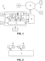
- a vehicle controller 10 is shown in FIG. 1 .
- the vehicle controller 10 is a controller for a transmission 11; however, it is understood that the vehicle controller 10 may form a portion of a controller used for controlling multiple vehicle systems.
- the vehicle controller 10 includes a control unit portion 12; a diagnostic module 14 in communication with a control sensor 16 and optionally with a diagnostic sensor 18; a prognostic module 20 in communication with the control sensor 16 and optionally with the diagnostic sensor 18; and a telematics interface 22. It is understood that in a preferred embodiment of the vehicle controller 10, the diagnostic sensor 18 is not needed; however, in some embodiments of the vehicle controller 10, the diagnostic sensor 18 may be included.
- the telematics interface 22 is in communication with a vehicle dashboard 24, the control unit portion 12, the diagnostic module 14, the prognostic module 20, and a computer network 26 (which may be commonly referred to as a cloud).
- vehicle dashboard 24 provides information to an operator of a vehicle (not shown) the vehicle controller 10 is incorporated in.
- Two way communication is provided between the control unit portion 12 and the diagnostic module 14, the control unit portion 12 and the prognostic module 20, and the control unit portion 12 and the telematics interface 22.
- the control unit portion 12 is used to initiate shifting procedures in the transmission 11 the vehicle controller 10 is in communication with.
- the vehicle controller 10 provides enhanced interaction between the diagnostic module 14 and the prognostic module 20 and the control unit portion 12.
- the enhanced interaction is schematically illustrated in FIG. 2 .
- the enhanced interaction is performed in various ways, which are described hereinbelow.
- a plurality of control settings and system parameters 28 learned by the vehicle controller 10 are sent to the diagnostic module 14 and the prognostic module 20.
- the control settings and system parameters 28 are compared to previously stored data (which has been supplemented with data obtained from the telematics interface 22 or statistical information obtained from testing of a system including the vehicle controller 10) to determine if a fault is present and what effects the control settings and system parameters 28 will have on the system including the vehicle controller 10.
- An imminent failure of a component or a rapid wearing of a component of the system including the vehicle controller 10 which is detected by one of the diagnostic module 14 and the prognostic module 20 is defined as a fault. If a fault is present, the vehicle controller 10 will attempt to keep the vehicle in an operational state as long as possible. Preferably, the vehicle controller 10 will attempt to keep the vehicle in an operational state until maintenance can be performed. The vehicle controller 10 may use the information detected by one of the diagnostic module14 and the prognostic module 20 to adjust shifting procedures in the transmission 11, such as through an adjustment made to a pressure profile of a clutch.
- a long term evolution of the control settings and system parameters 28 may be provided to the diagnostic module 14 and the prognostics module 20 so that the diagnostic module 14 and the prognostic module 20 can predict a remaining life of components of the transmission 11 and of a lubricant used with the transmission 11.
- the prognostic module 20 might interact through the telematics interface 22 to schedule maintenance of the vehicle or to provide information to a central fleet management controller 30.
- the prognostic module 20 might also be used to determine if the long term evolution of the control settings and system parameters 28 are consistent with expectations and empirical and theoretical models of the control settings and system parameters 28.
- the telematics interface 22 may also be used to:
- Telematics used in for the above described applications might include inputs from many interfaces such as a smartphone, a tablet style computer, a vehicle based computer, and a warehouse based computer, as non-limiting examples.
- Any of the aforementioned devices may be used to display information regarding any of the vehicles from a fleet of vehicles.
- Any of the aforementioned devices may also allow users of the devices to perform actions in response to the displayed information.
- the vehicle controller 10 including the above describes modules 14, 20 provides many innovative benefits over conventional controllers used with vehicles.
- One benefit of the vehicle controller 10 is the integration between the control unit portion 12, the diagnostic module 14, and the prognostic module 20.
- the above described integration provides an increased reliability of the prognostic module 20 and the diagnostic module 14 based on an evolution of the control parameters.
- Another benefit of the vehicle controller 10 is to leverage the prognostic module 20 and the diagnostic module 14 using feedback to the control unit portion 12, not just to the operator (such as through, but not limited to, the vehicle dashboard 24 or the telematics interface 22) and/or the central fleet management controller 30.
- information collected by the prognostic module 20 and the diagnostic module 14 may be used to adjust a shifting strategy or control parameters depending on determinations made by the prognostic module 20 and the diagnostic module 14.
- all of the information generated using the above described processes may be stored in the computer network 26 and may be shared with other vehicles in the fleet, with at least one infrastructure component (not shown), and with at least one maintenance component, for example, through the assistance of the telematics interface 22.
Landscapes
- Engineering & Computer Science (AREA)
- General Engineering & Computer Science (AREA)
- Physics & Mathematics (AREA)
- Fluid Mechanics (AREA)
- Mechanical Engineering (AREA)
- Control Of Transmission Device (AREA)
- Automobile Manufacture Line, Endless Track Vehicle, Trailer (AREA)
Description
- The invention relates to control of vehicle systems and, more particularly, to a controller and method for updating a plurality of control settings and system parameters.
- A wet-clutch, stepped ratio transmission may incorporate the function of being able to learn control settings and system parameters during operation of a vehicle the wet-clutch, stepped ratio transmission is incorporated in. Monitoring the variation of the control settings and the system parameters over short and long term periods of time provides many benefits. Monitoring the variation allows a system to diagnose transmission problems, to predict a remaining useful life of the transmission or a transmission component, or predict a time of failure of the transmission or a transmission component. Furthermore, such information regarding remaining useful life, component wear, and component failure can be used to adapt how the transmission is controlled.
- In most vehicle controllers, especially in the automotive sector, information gathered from a plurality of sensors (both from control systems and purpose-specific sensors) may be used in a diagnostics and prognostics system to detect component failure and to assist in a maintenance schedule of a vehicle including the diagnostics and prognostics system.
- Typically, on-board diagnostic (OBD) systems used in vehicles use one-way communication, which is most commonly used for signaling problems to an operator of the vehicle. The on-board diagnostic system, in some cases, may be configured to communicate over a wireless connection to other devices.
- Prognostics systems are used less often in vehicles, especially in off-highway applications, where maintenance is typically planned after a certain number of operating hours, other pre-determined intervals, or after a predetermined number of clutch engagements, for example.
- Recently, wet clutch transmissions have been developed that include systems incorporating learning parameters. When performing a shift between two gears, for example, a pressure profile may be analyzed to determine if the shift is correctly performed. If one or more anomalies are detected, the parameters may be adapted using online algorithms. Non-limiting examples of parameters which may be adjusted using such algorithms are fill pressure, timing (a duration of a filling of the clutch), and kiss pressure.
- Learned parameters might vary because of real working conditions being different from a set of initial operating conditions for which the transmission was designed. Non-limiting examples of such conditions are temperature fluctuation and lubricant variability. Such parameters will also vary over time because of a wearing of the clutches, an oxidation of the lubricant, or other effects. Such variations over time can be interpreted to help the diagnostic and prognostic system by providing the system with additional information.
- It would be advantageous to develop a vehicle controller including a diagnostics and prognostics module used with a vehicle transmission that provides enhanced interaction within and to and from the controller.
- Document
US 2010/100259 A1 relates to a fault diagnosis device for optimizing maintenance measures in a system, in particular a flying object. The diagnosis device has a storage unit for storing diagnosis rules, a logic unit, which logically combines stored fault conclusions and on the basis of the combined fault conclusions, determines a logical diagnosis result having at least one fault cause hypothesis. A calculation unit subsequently calculates an occurrence probability for each fault cause hypothesis of the logical diagnosis result determined. - Document
US 2009/254240 A1 relates to a system that enables a fleet of vehicles to be maintained. The system allows a fleet operator to review the history of the vehicles in the fleet along with vehicle sensor data to identify earmarks in the vehicle sensor data that are predictive of faults that the vehicles have experienced. The system collects vehicle sensor data and applies statistical algorithms to the vehicle data to determine if a potential fault is going to occur in a vehicle and in response to the determining that a potential fault is going to occur, the disclosed system automatically alerts the vehicle driver, automatically schedule a maintenance visit, automatically check the fleet inventory for components required for a maintenance visit and order unavailable components, and automatically dispatch the components to the mechanic. - Document
US 2002/049535 A1 relates to a wireless interactive voice-actuated mobile information system permits a motorist to obtain information and assistance, hands free, using voice technology and the Internet. An on-board telematics unit in a motor vehicle connects using wireless (cellular) communications with the Internet while the vehicle is underway. - Document
WO 2010/030341 A1 relates to a fleet management system provided for capturing, storing, and analyzing telematics data to improve fleet management operations. The fleet management system may be used, for example, to analyze engine idle data in relation to other telematics data in order to identify inefficiencies, safety hazards, and theft hazards in a driver's delivery process. The fleet management system may also be configured to assess various aspects of vehicle performance, such as vehicle travel delays and vehicle speeds. - Document
US 2010/207754 A1 relates to RFID and sensor assemblies for vehicles in which an interrogator transmits RF signals and receives responsive RF signals from the RFID assemblies. - None of the prior art documents disclose to adjust shifting procedures of a transmission of a vehicle system by a controller in response to plurality of control settings and system parameters.
- Presently provided by the invention, a vehicle controller including a diagnostics and prognostics module used with a vehicle transmission that provides enhanced interaction within and to and from the controller, has surprisingly been discovered
- In one embodiment, the present invention is directed to a controller for a vehicle system. The controller comprises a control unit portion, a prognostic module, a diagnostic module, and a telematics interface. The control unit portion is in communication with the vehicle system to initiate a vehicle system procedure. The prognostic module is in two way communication with the control unit portion. The diagnostic module is in communication with the prognostic module and is in two way communication with the control unit portion. The telematics interface is in two way communication with the control unit portion. A plurality of control settings and system parameters are sent to one of the diagnostic module and the prognostic module to be compared with previously stored data stored in one of the diagnostic module and the prognostic module.
- In another embodiment, the present invention is directed to a method for updating a plurality of control settings and system parameters for a controller for a vehicle system. The method comprising the steps of providing a control unit portion in communication with the vehicle system to initiate a vehicle system procedure, providing a prognostic module in two way communication with the control unit portion, providing a diagnostic module in communication with the prognostic module and in two way communication with the control unit portion, providing a telematics interface in two way communication with the control unit portion, sending a plurality of control settings and system parameters to one of the diagnostic module and the prognostic module, and comparing the plurality of control settings and system parameters sent to one of the diagnostic module and the prognostic module to previously stored data stored in one of the diagnostic module and the prognostic module.
-
-
FIG. 1 is a schematic illustration of a controller for a vehicle system according to the present invention; and -
FIG. 2 is a schematic illustration of a portion of the controller for a vehicle system illustrated inFIG. 1 . - It is to be understood that the invention may assume various alternative orientations and step sequences, except where expressly specified to the contrary. It is also to be understood that the specific devices and processes illustrated in the attached drawings, and described in the following specification are simply exemplary embodiments of the inventive concepts defined herein. Hence, specific dimensions, directions or other physical characteristics relating to the embodiments disclosed are not to be considered as limiting, unless expressly stated otherwise.
- A
vehicle controller 10 is shown inFIG. 1 . Thevehicle controller 10 is a controller for atransmission 11; however, it is understood that thevehicle controller 10 may form a portion of a controller used for controlling multiple vehicle systems. Thevehicle controller 10 includes acontrol unit portion 12; adiagnostic module 14 in communication with acontrol sensor 16 and optionally with adiagnostic sensor 18; aprognostic module 20 in communication with thecontrol sensor 16 and optionally with thediagnostic sensor 18; and atelematics interface 22. It is understood that in a preferred embodiment of thevehicle controller 10, thediagnostic sensor 18 is not needed; however, in some embodiments of thevehicle controller 10, thediagnostic sensor 18 may be included. Thetelematics interface 22 is in communication with avehicle dashboard 24, thecontrol unit portion 12, thediagnostic module 14, theprognostic module 20, and a computer network 26 (which may be commonly referred to as a cloud). Thevehicle dashboard 24 provides information to an operator of a vehicle (not shown) thevehicle controller 10 is incorporated in. Two way communication is provided between thecontrol unit portion 12 and thediagnostic module 14, thecontrol unit portion 12 and theprognostic module 20, and thecontrol unit portion 12 and thetelematics interface 22. Thecontrol unit portion 12 is used to initiate shifting procedures in thetransmission 11 thevehicle controller 10 is in communication with. - The
vehicle controller 10 provides enhanced interaction between thediagnostic module 14 and theprognostic module 20 and thecontrol unit portion 12. The enhanced interaction is schematically illustrated inFIG. 2 . The enhanced interaction is performed in various ways, which are described hereinbelow. - A plurality of control settings and
system parameters 28 learned by thevehicle controller 10 are sent to thediagnostic module 14 and theprognostic module 20. The control settings andsystem parameters 28 are compared to previously stored data (which has been supplemented with data obtained from thetelematics interface 22 or statistical information obtained from testing of a system including the vehicle controller 10) to determine if a fault is present and what effects the control settings andsystem parameters 28 will have on the system including thevehicle controller 10. - An imminent failure of a component or a rapid wearing of a component of the system including the
vehicle controller 10 which is detected by one of thediagnostic module 14 and theprognostic module 20 is defined as a fault. If a fault is present, thevehicle controller 10 will attempt to keep the vehicle in an operational state as long as possible. Preferably, thevehicle controller 10 will attempt to keep the vehicle in an operational state until maintenance can be performed. Thevehicle controller 10 may use the information detected by one of the diagnostic module14 and theprognostic module 20 to adjust shifting procedures in thetransmission 11, such as through an adjustment made to a pressure profile of a clutch. - The
vehicle controller 10 may avoid the use of one or more clutch or gear selection. It is understood that as a result, thevehicle controller 10 may perform double swap shifts. When a double swap shift is performed, two clutches are released and two different clutches are applied. - The
vehicle controller 10 may perform upshifts or downshifts in a reduced amount of time to reduce an amount of time spent in a particular gear ratio. - Additionally, a long term evolution of the control settings and
system parameters 28 may be provided to thediagnostic module 14 and theprognostics module 20 so that thediagnostic module 14 and theprognostic module 20 can predict a remaining life of components of thetransmission 11 and of a lubricant used with thetransmission 11. In performing this task, theprognostic module 20 might interact through thetelematics interface 22 to schedule maintenance of the vehicle or to provide information to a centralfleet management controller 30. Theprognostic module 20 might also be used to determine if the long term evolution of the control settings andsystem parameters 28 are consistent with expectations and empirical and theoretical models of the control settings andsystem parameters 28. - Additionally, the
telematics interface 22 may also be used to: - Signal a need for maintenance to the central
fleet management controller 30 - Perform at least a portion of diagnostic and prognostic calculations offline (for example, calculations to be performed on a remote computing device 32), where performing such calculations on the
remote computing device 32 results in increased precision of the diagnostic and prognostic calculations - Use information about an operating environment of the vehicle (for example, a conditions of the weather the vehicle is currently operating in, a gradient of a road the vehicle is traversing, and a roughness of a road the vehicle is traversing) in the
diagnostic module 14 and theprognostic module 20 - Use information from other vehicles obtained through the central
fleet management controller 30 and continuously adapt the interpretation of the signals from other vehicles by enriching a database 34 (accessed via the computer network 26) of themodules - Telematics used in for the above described applications might include inputs from many interfaces such as a smartphone, a tablet style computer, a vehicle based computer, and a warehouse based computer, as non-limiting examples. Any of the aforementioned devices may be used to display information regarding any of the vehicles from a fleet of vehicles. Any of the aforementioned devices may also allow users of the devices to perform actions in response to the displayed information.
- Compared to the state of the art, the
vehicle controller 10 including the above describesmodules vehicle controller 10 is the integration between thecontrol unit portion 12, thediagnostic module 14, and theprognostic module 20. The above described integration provides an increased reliability of theprognostic module 20 and thediagnostic module 14 based on an evolution of the control parameters. - Another benefit of the
vehicle controller 10 is to leverage theprognostic module 20 and thediagnostic module 14 using feedback to thecontrol unit portion 12, not just to the operator (such as through, but not limited to, thevehicle dashboard 24 or the telematics interface 22) and/or the centralfleet management controller 30. As a non-limiting example, information collected by theprognostic module 20 and thediagnostic module 14 may be used to adjust a shifting strategy or control parameters depending on determinations made by theprognostic module 20 and thediagnostic module 14. Additionally, all of the information generated using the above described processes may be stored in thecomputer network 26 and may be shared with other vehicles in the fleet, with at least one infrastructure component (not shown), and with at least one maintenance component, for example, through the assistance of thetelematics interface 22.
Claims (12)
- A controller (10) for a vehicle system, the controller (10) comprising:a control unit portion (12) in communication with the vehicle system to initiate a vehicle system procedure, wherein the vehicle system is a transmission (11);(12); a prognostic module (20) in two way communication with the control unit portiona diagnostic module (14) in communication with the prognostic module (20) and in two way communication with the control unit portion (12); anda telematics interface (22) in two way communication with the control unit portion (12), wherein a plurality of control settings and system parameters (28) are sent to one of the diagnostic module (14) and the prognostic module (20) to be compared with previously stored data stored in one of the diagnostic module (14) and the prognostic module (20); andwherein in response to the plurality of control settings and system parameters (28) the controller (10) is configured to adjust the shifting procedures of the transmission (11) by being configured to: either adjust a pressure profile of a clutch, avoid the use of one or more clutch or gear selections, or perform double swap shifts .
- The controller (10) according to claim 1, further comprising at least one of:a vehicle dashboard (24) in communication with the telematics interface (22), the control unit portion (12), the prognostic module (20), and the diagnostic module (14);a control sensor (16), the diagnostic module (14) and the prognostic module (20) in communication with the control sensor (16); anda diagnostic sensor (18), the diagnostic module (14) and the prognostic module (20) in communication with the diagnostic sensor (18).
- The controller (10) according to claim 1, wherein the telematics interface (22) is in two way communication with a computer network (26), and/or wherein the plurality of control settings and system parameters (28) are supplemented with data obtained from the telematics interface (22), and/or wherein the plurality of control settings and system parameters (28) are supplemented with statistical information obtained from testing of the transmission (11).
- The controller (10) according to claim 3, wherein the diagnostic module (14) and the prognostic module (20) are used to predict a condition of the transmission (11) based on a long term evolution of the control settings and system parameters (28).
- The controller (10) according to claim 4, wherein the prognostic module (20) interacts with the telematics interface (22) to schedule vehicle maintenance or to provide information to a central fleet management controller (30); and/or
wherein the prognostic module (20) is used to determine if the long term evolution of the control settings and system parameters (28) are consistent with empirical and theoretical models of the control settings and system parameters (28). - The controller (10) according to claim 1, wherein the telematics interface (22) performs at least a portion of diagnostic and prognostic calculations in an offline manner to increase a precision of the diagnostic and prognostic calculations.
- The controller (10) according to claim 3, wherein the telematics interface (22) uses information about an operating environment of the vehicle in the diagnostic module (14) and the prognostic module (20).
- The controller (10) according to claim 3, wherein the telematics interface (22) uses information from other vehicles obtained through a computer network (26).
- The controller (10) according to claim 8, wherein the telematics interface (22) adapts the interpretation of the signals from other vehicles through a central fleet management controller (30) in order to continuously adapt the interpretation of signals received from the other vehicles by enriching a database (34).
- A method for updating a plurality of control settings and system parameters (28) for a controller (10) for a vehicle system, the method comprising the steps of:providing a control unit portion (12) in communication with the vehicle system to initiate a vehicle system procedure, wherein the vehicle system is a transmission (11);providing a prognostic module (20) in two way communication with the control unit portion (12);providing a diagnostic module (14) in communication with the prognostic module (20) and in two way communication with the control unit portion (12);providing a telematics interface (22) in two way communication with the control unit portion (12);sending a plurality of control settings and system parameters (28) to one of the diagnostic module (14) and the prognostic module (20); and comparing the plurality of control settings and system parameters (28) sent to one of the diagnostic module (14) and the prognostic module (20) to previously stored data stored in one of the diagnostic module (14) and the prognostic module (20); andmaintaining the transmission (11) in an operational condition, wherein in response to the plurality of control settings and system parameters (28) the controller (10) adjusts the shifting procedures of the transmission (11) to: either adjusting a pressure profile of a clutch, or by avoiding the use of one or more clutch or gear selections, by performing double swap shifts .
- The method according to claim 10, further comprising providing a vehicle dashboard (24) in communication with the telematics interface (22), the control unit portion (12), the prognostic module (20), and the diagnostic module (14).
- The method according to claim 10, further comprising providing a control sensor (16) and at least one diagnostic sensor (18), wherein the diagnostic module (14) and the prognostic module (20) are in communication with the control sensor (16) and the at least one diagnostic sensor (18).
Applications Claiming Priority (2)
| Application Number | Priority Date | Filing Date | Title |
|---|---|---|---|
| US201361875181P | 2013-09-09 | 2013-09-09 | |
| PCT/US2014/054688 WO2015035355A2 (en) | 2013-09-09 | 2014-09-09 | Clutch control with integrated diagnostics/prognostics and telematics interface |
Publications (2)
| Publication Number | Publication Date |
|---|---|
| EP3044471A2 EP3044471A2 (en) | 2016-07-20 |
| EP3044471B1 true EP3044471B1 (en) | 2022-02-09 |
Family
ID=51582531
Family Applications (1)
| Application Number | Title | Priority Date | Filing Date |
|---|---|---|---|
| EP14771480.2A Not-in-force EP3044471B1 (en) | 2013-09-09 | 2014-09-09 | Clutch control with integrated diagnostics/prognostics and telematics interface |
Country Status (3)
| Country | Link |
|---|---|
| US (1) | US10174797B2 (en) |
| EP (1) | EP3044471B1 (en) |
| WO (1) | WO2015035355A2 (en) |
Family Cites Families (13)
| Publication number | Priority date | Publication date | Assignee | Title |
|---|---|---|---|---|
| US6738697B2 (en) * | 1995-06-07 | 2004-05-18 | Automotive Technologies International Inc. | Telematics system for vehicle diagnostics |
| US7786864B1 (en) * | 2000-09-08 | 2010-08-31 | Automotive Technologies International, Inc. | Vehicular RFID and sensor assemblies |
| US7650210B2 (en) * | 1995-06-07 | 2010-01-19 | Automotive Technologies International, Inc. | Remote vehicle diagnostic management |
| US7313467B2 (en) * | 2000-09-08 | 2007-12-25 | Automotive Technologies International Inc. | System and method for in-vehicle communications |
| US8024084B2 (en) * | 1995-06-07 | 2011-09-20 | Automotive Technologies International, Inc. | Vehicle diagnostic techniques |
| US8169311B1 (en) * | 1999-12-15 | 2012-05-01 | Automotive Technologies International, Inc. | Wireless transmission system for vehicular component control and monitoring |
| US7630802B2 (en) * | 1995-06-07 | 2009-12-08 | Automotive Technologies International, Inc. | Information management and monitoring system and method |
| US8229624B2 (en) * | 1995-06-07 | 2012-07-24 | American Vehicular Sciences Llc | Vehicle diagnostic information generating and transmission systems and methods |
| US8019501B2 (en) * | 1995-06-07 | 2011-09-13 | Automotive Technologies International, Inc. | Vehicle diagnostic and prognostic methods and systems |
| US20020049535A1 (en) * | 1999-09-20 | 2002-04-25 | Ralf Rigo | Wireless interactive voice-actuated mobile telematics system |
| US9026304B2 (en) | 2008-04-07 | 2015-05-05 | United Parcel Service Of America, Inc. | Vehicle maintenance systems and methods |
| CN102203810A (en) | 2008-09-09 | 2011-09-28 | 美国联合包裹服务公司 | Systems and methods of utilizing telematics data to improve fleet management operations |
| US8442702B2 (en) | 2008-10-22 | 2013-05-14 | Airbus Operations Gmbh | Fault diagnosis device and method for optimizing maintenance measures in technical systems |
-
2014
- 2014-09-09 US US14/392,377 patent/US10174797B2/en not_active Expired - Fee Related
- 2014-09-09 WO PCT/US2014/054688 patent/WO2015035355A2/en not_active Ceased
- 2014-09-09 EP EP14771480.2A patent/EP3044471B1/en not_active Not-in-force
Also Published As
| Publication number | Publication date |
|---|---|
| WO2015035355A3 (en) | 2015-11-19 |
| EP3044471A2 (en) | 2016-07-20 |
| WO2015035355A2 (en) | 2015-03-12 |
| US10174797B2 (en) | 2019-01-08 |
| US20160223034A1 (en) | 2016-08-04 |
Similar Documents
| Publication | Publication Date | Title |
|---|---|---|
| US20220391854A1 (en) | Predictive Maintenance | |
| US10062219B2 (en) | Method for determining the cause of failure in a vehicle | |
| EP3740405B1 (en) | Vehicle failure warning system and corresponding vehicle failure warning method | |
| CN109421630B (en) | Controller architecture for monitoring health of autonomous vehicles | |
| KR101500091B1 (en) | Apparatus for controlling vehicle and system thereof | |
| US8346429B2 (en) | Vehicle health monitoring system architecture for diagnostics and prognostics disclosure | |
| US9229904B2 (en) | Diagnostic method and diagnostic device for a vehicle component of a vehicle | |
| US6609051B2 (en) | Method and system for condition monitoring of vehicles | |
| US9734001B2 (en) | Efficient health management, diagnosis and prognosis of a machine | |
| US20190255891A1 (en) | System and method for tire wear prognostics | |
| US8346700B2 (en) | Vehicle health monitoring reasoner architecture for diagnostics and prognostics | |
| WO2017051032A1 (en) | A method for estimating the need for maintenance of a component | |
| US10861251B2 (en) | Vehicle maintenance operation | |
| US12249191B2 (en) | Method for determining the operating state of vehicle components | |
| CN110356462A (en) | stowable steering wheel | |
| KR102934952B1 (en) | Automatic transmission diagnosing device and method | |
| EP3731201B1 (en) | A support system for an operator | |
| JP6594826B2 (en) | Vehicle diagnostic device | |
| US10174797B2 (en) | Clutch control with integrated diagnostics/prognostics and telematics interface | |
| KR102833885B1 (en) | Method and system for predicting vehicle failure | |
| US20230162542A1 (en) | Device and method for handling a data associated with energy consumption of a vehicle | |
| US12026996B2 (en) | Vehicle data storage activation | |
| DE102023201378A1 (en) | Method for assessing a vehicle operation of a vehicle and control device for controlling a vehicle operation of a vehicle | |
| WO2022243156A1 (en) | Prediction device and prediction method for at least one brake system component of a brake system of an ego vehicle | |
| US20250391204A1 (en) | Systems for individualized vehicle maintenance and repair |
Legal Events
| Date | Code | Title | Description |
|---|---|---|---|
| PUAI | Public reference made under article 153(3) epc to a published international application that has entered the european phase |
Free format text: ORIGINAL CODE: 0009012 |
|
| 17P | Request for examination filed |
Effective date: 20160308 |
|
| AK | Designated contracting states |
Kind code of ref document: A2 Designated state(s): AL AT BE BG CH CY CZ DE DK EE ES FI FR GB GR HR HU IE IS IT LI LT LU LV MC MK MT NL NO PL PT RO RS SE SI SK SM TR |
|
| AX | Request for extension of the european patent |
Extension state: BA ME |
|
| DAX | Request for extension of the european patent (deleted) | ||
| STAA | Information on the status of an ep patent application or granted ep patent |
Free format text: STATUS: EXAMINATION IS IN PROGRESS |
|
| 17Q | First examination report despatched |
Effective date: 20190710 |
|
| GRAP | Despatch of communication of intention to grant a patent |
Free format text: ORIGINAL CODE: EPIDOSNIGR1 |
|
| STAA | Information on the status of an ep patent application or granted ep patent |
Free format text: STATUS: GRANT OF PATENT IS INTENDED |
|
| INTG | Intention to grant announced |
Effective date: 20210831 |
|
| GRAS | Grant fee paid |
Free format text: ORIGINAL CODE: EPIDOSNIGR3 |
|
| GRAA | (expected) grant |
Free format text: ORIGINAL CODE: 0009210 |
|
| STAA | Information on the status of an ep patent application or granted ep patent |
Free format text: STATUS: THE PATENT HAS BEEN GRANTED |
|
| AK | Designated contracting states |
Kind code of ref document: B1 Designated state(s): AL AT BE BG CH CY CZ DE DK EE ES FI FR GB GR HR HU IE IS IT LI LT LU LV MC MK MT NL NO PL PT RO RS SE SI SK SM TR |
|
| REG | Reference to a national code |
Ref country code: GB Ref legal event code: FG4D |
|
| REG | Reference to a national code |
Ref country code: CH Ref legal event code: EP Ref country code: AT Ref legal event code: REF Ref document number: 1467691 Country of ref document: AT Kind code of ref document: T Effective date: 20220215 |
|
| REG | Reference to a national code |
Ref country code: IE Ref legal event code: FG4D |
|
| REG | Reference to a national code |
Ref country code: DE Ref legal event code: R096 Ref document number: 602014082438 Country of ref document: DE |
|
| REG | Reference to a national code |
Ref country code: LT Ref legal event code: MG9D |
|
| REG | Reference to a national code |
Ref country code: NL Ref legal event code: MP Effective date: 20220209 |
|
| REG | Reference to a national code |
Ref country code: AT Ref legal event code: MK05 Ref document number: 1467691 Country of ref document: AT Kind code of ref document: T Effective date: 20220209 |
|
| PG25 | Lapsed in a contracting state [announced via postgrant information from national office to epo] |
Ref country code: SE Free format text: LAPSE BECAUSE OF FAILURE TO SUBMIT A TRANSLATION OF THE DESCRIPTION OR TO PAY THE FEE WITHIN THE PRESCRIBED TIME-LIMIT Effective date: 20220209 Ref country code: RS Free format text: LAPSE BECAUSE OF FAILURE TO SUBMIT A TRANSLATION OF THE DESCRIPTION OR TO PAY THE FEE WITHIN THE PRESCRIBED TIME-LIMIT Effective date: 20220209 Ref country code: PT Free format text: LAPSE BECAUSE OF FAILURE TO SUBMIT A TRANSLATION OF THE DESCRIPTION OR TO PAY THE FEE WITHIN THE PRESCRIBED TIME-LIMIT Effective date: 20220609 Ref country code: NO Free format text: LAPSE BECAUSE OF FAILURE TO SUBMIT A TRANSLATION OF THE DESCRIPTION OR TO PAY THE FEE WITHIN THE PRESCRIBED TIME-LIMIT Effective date: 20220509 Ref country code: NL Free format text: LAPSE BECAUSE OF FAILURE TO SUBMIT A TRANSLATION OF THE DESCRIPTION OR TO PAY THE FEE WITHIN THE PRESCRIBED TIME-LIMIT Effective date: 20220209 Ref country code: LT Free format text: LAPSE BECAUSE OF FAILURE TO SUBMIT A TRANSLATION OF THE DESCRIPTION OR TO PAY THE FEE WITHIN THE PRESCRIBED TIME-LIMIT Effective date: 20220209 Ref country code: HR Free format text: LAPSE BECAUSE OF FAILURE TO SUBMIT A TRANSLATION OF THE DESCRIPTION OR TO PAY THE FEE WITHIN THE PRESCRIBED TIME-LIMIT Effective date: 20220209 Ref country code: ES Free format text: LAPSE BECAUSE OF FAILURE TO SUBMIT A TRANSLATION OF THE DESCRIPTION OR TO PAY THE FEE WITHIN THE PRESCRIBED TIME-LIMIT Effective date: 20220209 Ref country code: BG Free format text: LAPSE BECAUSE OF FAILURE TO SUBMIT A TRANSLATION OF THE DESCRIPTION OR TO PAY THE FEE WITHIN THE PRESCRIBED TIME-LIMIT Effective date: 20220509 |
|
| PG25 | Lapsed in a contracting state [announced via postgrant information from national office to epo] |
Ref country code: PL Free format text: LAPSE BECAUSE OF FAILURE TO SUBMIT A TRANSLATION OF THE DESCRIPTION OR TO PAY THE FEE WITHIN THE PRESCRIBED TIME-LIMIT Effective date: 20220209 Ref country code: LV Free format text: LAPSE BECAUSE OF FAILURE TO SUBMIT A TRANSLATION OF THE DESCRIPTION OR TO PAY THE FEE WITHIN THE PRESCRIBED TIME-LIMIT Effective date: 20220209 Ref country code: GR Free format text: LAPSE BECAUSE OF FAILURE TO SUBMIT A TRANSLATION OF THE DESCRIPTION OR TO PAY THE FEE WITHIN THE PRESCRIBED TIME-LIMIT Effective date: 20220510 Ref country code: FI Free format text: LAPSE BECAUSE OF FAILURE TO SUBMIT A TRANSLATION OF THE DESCRIPTION OR TO PAY THE FEE WITHIN THE PRESCRIBED TIME-LIMIT Effective date: 20220209 Ref country code: AT Free format text: LAPSE BECAUSE OF FAILURE TO SUBMIT A TRANSLATION OF THE DESCRIPTION OR TO PAY THE FEE WITHIN THE PRESCRIBED TIME-LIMIT Effective date: 20220209 |
|
| PG25 | Lapsed in a contracting state [announced via postgrant information from national office to epo] |
Ref country code: IS Free format text: LAPSE BECAUSE OF FAILURE TO SUBMIT A TRANSLATION OF THE DESCRIPTION OR TO PAY THE FEE WITHIN THE PRESCRIBED TIME-LIMIT Effective date: 20220609 |
|
| PG25 | Lapsed in a contracting state [announced via postgrant information from national office to epo] |
Ref country code: SM Free format text: LAPSE BECAUSE OF FAILURE TO SUBMIT A TRANSLATION OF THE DESCRIPTION OR TO PAY THE FEE WITHIN THE PRESCRIBED TIME-LIMIT Effective date: 20220209 Ref country code: SK Free format text: LAPSE BECAUSE OF FAILURE TO SUBMIT A TRANSLATION OF THE DESCRIPTION OR TO PAY THE FEE WITHIN THE PRESCRIBED TIME-LIMIT Effective date: 20220209 Ref country code: RO Free format text: LAPSE BECAUSE OF FAILURE TO SUBMIT A TRANSLATION OF THE DESCRIPTION OR TO PAY THE FEE WITHIN THE PRESCRIBED TIME-LIMIT Effective date: 20220209 Ref country code: EE Free format text: LAPSE BECAUSE OF FAILURE TO SUBMIT A TRANSLATION OF THE DESCRIPTION OR TO PAY THE FEE WITHIN THE PRESCRIBED TIME-LIMIT Effective date: 20220209 Ref country code: DK Free format text: LAPSE BECAUSE OF FAILURE TO SUBMIT A TRANSLATION OF THE DESCRIPTION OR TO PAY THE FEE WITHIN THE PRESCRIBED TIME-LIMIT Effective date: 20220209 Ref country code: CZ Free format text: LAPSE BECAUSE OF FAILURE TO SUBMIT A TRANSLATION OF THE DESCRIPTION OR TO PAY THE FEE WITHIN THE PRESCRIBED TIME-LIMIT Effective date: 20220209 |
|
| REG | Reference to a national code |
Ref country code: DE Ref legal event code: R097 Ref document number: 602014082438 Country of ref document: DE |
|
| PG25 | Lapsed in a contracting state [announced via postgrant information from national office to epo] |
Ref country code: AL Free format text: LAPSE BECAUSE OF FAILURE TO SUBMIT A TRANSLATION OF THE DESCRIPTION OR TO PAY THE FEE WITHIN THE PRESCRIBED TIME-LIMIT Effective date: 20220209 |
|
| PLBE | No opposition filed within time limit |
Free format text: ORIGINAL CODE: 0009261 |
|
| STAA | Information on the status of an ep patent application or granted ep patent |
Free format text: STATUS: NO OPPOSITION FILED WITHIN TIME LIMIT |
|
| 26N | No opposition filed |
Effective date: 20221110 |
|
| PG25 | Lapsed in a contracting state [announced via postgrant information from national office to epo] |
Ref country code: SI Free format text: LAPSE BECAUSE OF FAILURE TO SUBMIT A TRANSLATION OF THE DESCRIPTION OR TO PAY THE FEE WITHIN THE PRESCRIBED TIME-LIMIT Effective date: 20220209 |
|
| PG25 | Lapsed in a contracting state [announced via postgrant information from national office to epo] |
Ref country code: MC Free format text: LAPSE BECAUSE OF FAILURE TO SUBMIT A TRANSLATION OF THE DESCRIPTION OR TO PAY THE FEE WITHIN THE PRESCRIBED TIME-LIMIT Effective date: 20220209 |
|
| REG | Reference to a national code |
Ref country code: CH Ref legal event code: PL |
|
| GBPC | Gb: european patent ceased through non-payment of renewal fee |
Effective date: 20220909 |
|
| REG | Reference to a national code |
Ref country code: BE Ref legal event code: MM Effective date: 20220930 |
|
| P01 | Opt-out of the competence of the unified patent court (upc) registered |
Effective date: 20230524 |
|
| PG25 | Lapsed in a contracting state [announced via postgrant information from national office to epo] |
Ref country code: LU Free format text: LAPSE BECAUSE OF NON-PAYMENT OF DUE FEES Effective date: 20220909 |
|
| PG25 | Lapsed in a contracting state [announced via postgrant information from national office to epo] |
Ref country code: LI Free format text: LAPSE BECAUSE OF NON-PAYMENT OF DUE FEES Effective date: 20220930 Ref country code: IT Free format text: LAPSE BECAUSE OF FAILURE TO SUBMIT A TRANSLATION OF THE DESCRIPTION OR TO PAY THE FEE WITHIN THE PRESCRIBED TIME-LIMIT Effective date: 20220209 Ref country code: IE Free format text: LAPSE BECAUSE OF NON-PAYMENT OF DUE FEES Effective date: 20220909 Ref country code: FR Free format text: LAPSE BECAUSE OF NON-PAYMENT OF DUE FEES Effective date: 20220930 Ref country code: CH Free format text: LAPSE BECAUSE OF NON-PAYMENT OF DUE FEES Effective date: 20220930 |
|
| PG25 | Lapsed in a contracting state [announced via postgrant information from national office to epo] |
Ref country code: BE Free format text: LAPSE BECAUSE OF NON-PAYMENT OF DUE FEES Effective date: 20220930 |
|
| PG25 | Lapsed in a contracting state [announced via postgrant information from national office to epo] |
Ref country code: GB Free format text: LAPSE BECAUSE OF NON-PAYMENT OF DUE FEES Effective date: 20220909 |
|
| PGFP | Annual fee paid to national office [announced via postgrant information from national office to epo] |
Ref country code: DE Payment date: 20230822 Year of fee payment: 10 |
|
| PG25 | Lapsed in a contracting state [announced via postgrant information from national office to epo] |
Ref country code: HU Free format text: LAPSE BECAUSE OF FAILURE TO SUBMIT A TRANSLATION OF THE DESCRIPTION OR TO PAY THE FEE WITHIN THE PRESCRIBED TIME-LIMIT; INVALID AB INITIO Effective date: 20140909 |
|
| PG25 | Lapsed in a contracting state [announced via postgrant information from national office to epo] |
Ref country code: CY Free format text: LAPSE BECAUSE OF FAILURE TO SUBMIT A TRANSLATION OF THE DESCRIPTION OR TO PAY THE FEE WITHIN THE PRESCRIBED TIME-LIMIT Effective date: 20220209 |
|
| PG25 | Lapsed in a contracting state [announced via postgrant information from national office to epo] |
Ref country code: MK Free format text: LAPSE BECAUSE OF FAILURE TO SUBMIT A TRANSLATION OF THE DESCRIPTION OR TO PAY THE FEE WITHIN THE PRESCRIBED TIME-LIMIT Effective date: 20220209 |
|
| PG25 | Lapsed in a contracting state [announced via postgrant information from national office to epo] |
Ref country code: MT Free format text: LAPSE BECAUSE OF FAILURE TO SUBMIT A TRANSLATION OF THE DESCRIPTION OR TO PAY THE FEE WITHIN THE PRESCRIBED TIME-LIMIT Effective date: 20220209 |
|
| REG | Reference to a national code |
Ref country code: DE Ref legal event code: R119 Ref document number: 602014082438 Country of ref document: DE |
|
| PG25 | Lapsed in a contracting state [announced via postgrant information from national office to epo] |
Ref country code: DE Free format text: LAPSE BECAUSE OF NON-PAYMENT OF DUE FEES Effective date: 20250401 |
|
| PG25 | Lapsed in a contracting state [announced via postgrant information from national office to epo] |
Ref country code: TR Free format text: LAPSE BECAUSE OF FAILURE TO SUBMIT A TRANSLATION OF THE DESCRIPTION OR TO PAY THE FEE WITHIN THE PRESCRIBED TIME-LIMIT Effective date: 20220209 |