EP3044460B1 - Sole for footwears capable of recovering part of the energy produced during deambulation - Google Patents
Sole for footwears capable of recovering part of the energy produced during deambulation Download PDFInfo
- Publication number
- EP3044460B1 EP3044460B1 EP15711824.1A EP15711824A EP3044460B1 EP 3044460 B1 EP3044460 B1 EP 3044460B1 EP 15711824 A EP15711824 A EP 15711824A EP 3044460 B1 EP3044460 B1 EP 3044460B1
- Authority
- EP
- European Patent Office
- Prior art keywords
- sole
- tank
- sole according
- tubular body
- energy
- Prior art date
- Legal status (The legal status is an assumption and is not a legal conclusion. Google has not performed a legal analysis and makes no representation as to the accuracy of the status listed.)
- Active
Links
Images




Classifications
-
- A—HUMAN NECESSITIES
- A43—FOOTWEAR
- A43B—CHARACTERISTIC FEATURES OF FOOTWEAR; PARTS OF FOOTWEAR
- A43B3/00—Footwear characterised by the shape or the use
- A43B3/34—Footwear characterised by the shape or the use with electrical or electronic arrangements
- A43B3/38—Footwear characterised by the shape or the use with electrical or electronic arrangements with power sources
- A43B3/42—Footwear characterised by the shape or the use with electrical or electronic arrangements with power sources where power is generated by conversion of mechanical movement to electricity, e.g. by piezoelectric means
-
- A—HUMAN NECESSITIES
- A43—FOOTWEAR
- A43B—CHARACTERISTIC FEATURES OF FOOTWEAR; PARTS OF FOOTWEAR
- A43B3/00—Footwear characterised by the shape or the use
- A43B3/34—Footwear characterised by the shape or the use with electrical or electronic arrangements
- A43B3/38—Footwear characterised by the shape or the use with electrical or electronic arrangements with power sources
-
- F—MECHANICAL ENGINEERING; LIGHTING; HEATING; WEAPONS; BLASTING
- F03—MACHINES OR ENGINES FOR LIQUIDS; WIND, SPRING, OR WEIGHT MOTORS; PRODUCING MECHANICAL POWER OR A REACTIVE PROPULSIVE THRUST, NOT OTHERWISE PROVIDED FOR
- F03G—SPRING, WEIGHT, INERTIA OR LIKE MOTORS; MECHANICAL-POWER PRODUCING DEVICES OR MECHANISMS, NOT OTHERWISE PROVIDED FOR OR USING ENERGY SOURCES NOT OTHERWISE PROVIDED FOR
- F03G5/00—Devices for producing mechanical power from muscle energy
- F03G5/06—Devices for producing mechanical power from muscle energy other than of endless-walk type
- F03G5/062—Devices for producing mechanical power from muscle energy other than of endless-walk type driven by humans
- F03G5/063—Devices for producing mechanical power from muscle energy other than of endless-walk type driven by humans operated by the leg or foot
-
- H—ELECTRICITY
- H02—GENERATION; CONVERSION OR DISTRIBUTION OF ELECTRIC POWER
- H02N—ELECTRIC MACHINES NOT OTHERWISE PROVIDED FOR
- H02N11/00—Generators or motors not provided for elsewhere; Alleged perpetua mobilia obtained by electric or magnetic means
- H02N11/002—Generators
Definitions
- the present invention relates to a sole for footwear capable of recovering part of the energy produced during deambulation.
- EH energy harvesters
- photovoltaic cells which store solar energy in order to convert it into directly-usable energy, for example, for the operation of a calculator or a watch or other electronic devices.
- the energy harvesters available in the art are of different type according to the specific application; in the footwear field, a energy harvester has been recently proposed that is capable of storing the energy generated during deambulation in the form of pressure variations exerted by a foot on the shoe sole, in order to render such energy directly available for use.
- a harvester of this type has for example been proposed by the U.S. company InStep Nanopower.
- One such harvester is activated by a respective actuator group in response to the pressure variations exerted by the foot on the sole during deambulation.
- the actuator group comprises a fluid-dynamic circuit connected to the ends of the harvester.
- one such harvester only allows storing a minimum part of the energy produced during deambulation, with the result that the quantity of energy recovered by the harvester is not actually sufficient for allowing, for example, the power supply of electronic devices directly or remotely connected to the harvester itself.
- the main object, therefore, of the present invention is to improve the state of the art in the field of energy harvesting devices and, in particular, in the field of footwear.
- Another object of the present invention is to provide a sole for footwear that is capable of recovering energy produced during deambulation in a more efficient manner with respect to the previously-proposed soles of this type.
- Still another object of the present invention is to provide a sole for footwear that allows the power supply, both direct and remote, of new generation electronic devices.
- a further object of the present invention is to provide a sole for footwear capable of recovering energy produced during deambulation that has an alternative configuration with respect to the configuration of the previously-proposed footwear soles of this type.
- Not the least object of the present invention is to provide a sole for footwear capable of recovering energy produced during deambulation that is easy to obtain at competitive costs.
- a sole for footwear is provided that is capable of recovering energy produced during deambulation according to claim 1.
- a sole for footwear according to the present invention in the illustrated case a left-shoe sole, is indicated overall with the reference number 1 and has a rear area 2, provided in use for the heel support, a front area 3, provided in use for the support of the front portion of the foot, an outer side portion 4 and an inner side portion 5.
- the sole according to the present invention comprises at least one energy harvesting means 6, intended in use, as will be stated hereinbelow, to convert at least part of the energy produced during deambulation into electrical energy.
- Such energy harvester 6 is, for example, of the type and illustrated in WO 2014/028799 (particular reference is made to the Fig. 3 of such document) and comprises a tubular body 60, fixed during use, having a first end 61 and a second end 62.
- the energy harvester 6 further comprises a movable part or body 63, slidably inserted in the tubular body 60.
- the movable part or body 63 of the harvester 6 is, as is known, composed of a plurality of magnets 631, 632, ..., joined together to form a chain.
- the energy harvester 6 is preferably housed in a central portion of the sole, at a housing seat 45 provided for such purpose (see figure 3 ).
- the body 60 of the energy harvester 6 extends longitudinally with its first end 61 at an external lateral front area, and with the other end thereof, the second end 62, at an internal lateral rear area of the sole.
- the sole according to the present invention further comprises at least one actuator group 7 for operating the energy harvester 6.
- the actuator group 7 comprises a fluid-dynamic circuit including at least one first fluid tank 71 in fluid communication with the first end 61 of the tubular body 60 of the energy harvester 6 by means of a first joining conduit 81.
- the actuator group also comprises a second fluid tank 72, placed in fluid communication with the second end 62 of the tubular body 60 of the energy harvester 6 by means of a second joining conduit 82.
- the movable part 63 of the energy harvester 6 has longitudinal extension greater than the longitudinal extension of the tubular body 60; in the case illustrated in the figures, such longitudinal extension is approximately double the tubular body, such that it is partially housed in the joining conduits 81 and/or 82 of the actuator group 7.
- the movable part 63 of the energy harvester 6 is provided, during use, slidable to fit in the tubular body 60 and in the joining conduits 81 and 82 of the actuator group 7, both towards the first tank 71 and towards the second tank 72.
- the first tank 71 of the actuator group 7 is housed at the rear area 2 of the sole and has a configuration in plan view, which is substantially elongated and curved, U-shaped in the illustrated embodiment. More particularly, such tank 71 is arranged in the rear area 2 of the sole in a manner so as to have a blind end 711 thereof at the outer side portion 4 of the sole and the other end 712 thereof for connection with the first end 61 of the tubular body 60 at an inner side portion 5 of the sole itself.
- the fluid connection between the first tank 71 and the first end 61 occurs by means of the first joining conduit 81, connected to the tank by means of a fluid-seal connector 91.
- the second tank 72 of the sole is housed at the front area 3 of the sole and has a configuration in plan view which is substantially elongated, and more particularly polygonal, rectangular or parallelogram in the illustrated example.
- Such second tank 72 is housed in the sole transversely arranged in the front area 3, in a manner so as to have a blind end 721 thereof at an inner side portion 5 of the sole, and the other end 722 thereof, for connection with the second end 62 of the tubular body 60 at an outer side portion 4 of said sole.
- the blind end 721 of the tank 72 is more advanced in the sole with respect to the other end 722.
- the fluid connection between the second tank 72 and the second end 62 occurs by means of the second joining conduit 82, connected to the tank by means of a fluid-seal connector 92.
- the first and the second tank 71 and 72 are provided for containing a fluid F, preferably an inert and non-toxic liquid such as water or glycerin.
- a fluid F preferably an inert and non-toxic liquid such as water or glycerin.
- the tanks are also made of a non-rigid plastic material, for example thermoplastic polyurethane, and intended to be compressed under the weight of the foot during deambulation.
- the joining conduits 81 and 82 are instead made of a more rigid material, e.g. nylon, and are housed at a front area 3 and rear area 2 of the sole, respectively.
- the joining conduits 81 and 82 are extended in the respective portions of the sole, housed in housing seats, 30 and 20, respectively, obtained for such purpose, substantially along the perimeter edges of the sole.
- the first and the second joining conduit 81 and 82 of the actuator group 7 are in fluid connection with the respective tanks by means of seal conriectors 91 and 92.
- the fluid F contained in the tanks therefore, wets the ends of the movable body 63 of the energy harvester 6.
- the movable body 63 slides to size in the conduits 81 and 82, which will therefore have suitable size and will be made of a suitable material (at least on their internal surface) that minimizes the friction between the movable body and the conduit itself.
- the second tank 72 is compressed and the fluid F contained therein is thrust to return towards the connection end 722 of the tank itself and, by means of the joining conduit 82, towards the second end 62 of the tubular body 60 of the harvester 6.
- the movement of the fluid F causes the sliding of the movable body 63 in the harvester 6 towards the first tank 71.
- first and second tank 71 and 72 (more particularly of the first tank 71), their arrangement in the sole as well as the position of the respective fluid connection ends 712 and 722 allow optimizing the propulsive thrust of the fluid F inside the actuator group 7 during deambulation.
- the foot first strikes against the external rear portion of the heel, after which it strikes against the central portion and front portion , along the so-called "pronation" line, which actually represents a kind of "S".
- the arrangement of the harvester 6 and of the actuator group 7 allows the fluid F to follow this S-like line, thus optimizing the thrust on the movable body of the harvester 6 and, accordingly, the conversion of such thrust into electrical energy.
- the sole according to the present invention comprises a bypass portion 10 for direct fluid communication between the first and the second tank 71 and 72.
- Such bypass portion 10 acts as a group for regulating the pressures in the tanks. Indeed, it was verified that in some circumstances, although infrequently, the pressure exerted simultaneously on the first tank 71 and on the second tank 72 of the actuator group 7 is approximately the same in the same time interval, with the result that the fluid F contained in the tanks is substantially not moved between one tank and the other, and hence no thrust is generated on the movable body 63 of the energy harvester 6. Therefore, the energy produced with the deambulation is not converted into electrical energy.
- the bypass portion of the actuator group 7 comprises at least one delivery portion 101 and one return portion 102 between the tanks 72 and 71, in each portion a valve means 11 being mounted, preferably of nonreturn type.
- the bypass portion 10 is advantageously provided between the connection end 712 of the first tank 71 and a front central portion 723 of the second tank 72. It is made of the same material used for the tanks 71 and 72, and preferably is integral therewith.
- the bypass portion 10 of the sole according to the present invention is provided for allowing the passage of fluid F therethrough only if the pressure is substantially equal between the tanks or is too high, e.g. higher than a predetermined threshold value, in one of the tanks. In normal work conditions of the sole, there is no passage of the fluid into the delivery and return portions 101 and 102.
- the passage of fluid in the bypass portion 10 allows regulating the quantity of fluid F between the tanks and the pressures involved, such that during deambulation the movable body 63 of the energy harvester 6 is always moved by the fluid F with respect to the fixed body 60 and the energy produced with the deambulation is always converted into electrical energy.
- the sole for footwear according to the present invention also comprises means for accumulating/dispensing 12 (see figure 7 ) the electrical energy produced by the energy harvester 6.
- Such accumulating/dispensing means are electrically connected to the energy harvester 6 in a manner known for the man skilled in the art and allow delivering energy at variable frequency ranging from 0.1 to 1 KHz, low voltage and low output impedance, as illustrated by way of example in Figure 8 .
- the means are provided in the sole at the rear portion 2, for example supported by the sole itself, as illustrated in figure 7 , housed in a respective housing seat obtained therein, for example below the first tank 71.
- Such accumulating/dispensing 12 means are electrically connected to input/output means not illustrated in the drawings, for the connection of the sole to an electronic device.
- the input/output means can for example comprise a USB port, advantageously housed in a known manner in the sole or in another suitable place of the upper.
- the means for accumulating/dispensing 12 the electrical energy produced by the energy harvester 6 can also be directly connected to consumer electronic devices (also not depicted in the drawings) that are also housed in the sole.
- consumer electronic devices can, for example, comprise a GPS or one or more accelerometers or one or more sensors or one or more SOCs (system on chip) or a MP3 player or possible combinations thereof, in turn connectable, preferably remotely, to auxiliary consumer electronic devices, such as one or more LED lights and/or a computer and/or a smart-phone and/or a smart-watch and/or, in the case of the MP3 player, wireless head-phones.
- the energy harvesting means 6 can comprise a plurality of tubular sections or segments, arranged in series with each other to form the tubular body 60.
- the movable part or body 63 is slidably inserted in such sections or segments, as described above.
- Each section or segment of the plurality of sections or segments is electrically connected to the means for accumulating/dispensing energy 12.
- the means for accumulating/dispensing energy 12 advantageously comprise a plurality of rectifier means, preferably of active type with MOS and comparator, each arranged downstream of a respective energy harvester 6 or section or segment thereof, in turn electrically controlled by a selector group or MUX.
- a possible charge pump switching regulator may be present downstream of the selector group, if the energy harvesting means 6 provide an electrical pulse with voltage, after rectification, e.g. less than about 3V.
- the means for accumulating/dispensing energy 12 further comprise accumulator means, electrically connected downstream of the selector group and possible regulator, and advantageously comprising a supercapacitor, in technical jargon termed "supercap”, and a battery of the polymer/lithium ion type (or any other suitable type).
- the supercapacitor acts as a buffer for the battery, mitigating the effects due to the high voltage and current peaks, and providing a very low input impedance, in a manner so as to quickly accumulate (much faster than the battery) current pulses that are even quite high (on the order of tens of Amperes), without losing significant energy.
- the "supercap” then provides the battery with the energy temporarily accumulated in a continuous manner and with limited currents (on the order of hundreds of mA).
- the accumulator means allow effectively accumulating the energy delivered by the energy harvesting means 6 and make it constantly available for an electronic device of the type mentioned above and in the requested voltage.
- the sole according to the present invention has been described by taking under consideration a left shoe; of course, the present description holds true, mutatis mutandis, for a corresponding sole for a right shoe.
Landscapes
- Engineering & Computer Science (AREA)
- Chemical & Material Sciences (AREA)
- Combustion & Propulsion (AREA)
- Microelectronics & Electronic Packaging (AREA)
- Mechanical Engineering (AREA)
- General Engineering & Computer Science (AREA)
- Health & Medical Sciences (AREA)
- Toxicology (AREA)
- Footwear And Its Accessory, Manufacturing Method And Apparatuses (AREA)
Description
- The present invention relates to a sole for footwear capable of recovering part of the energy produced during deambulation.
- In the present description and the following claims, with the generic term "deambulation" it is intended the act of walking or running carried out by a person, while with the generic term "sole", it is intended the portion of the shoe comprising the outsole and the insole of the shoe itself.
- In the state of the art so-called "energy harvesters" (in brief, EH) are known, which are able to store the available energy in one environment in order to render it directly usable. One example known to all is represented by photovoltaic cells, which store solar energy in order to convert it into directly-usable energy, for example, for the operation of a calculator or a watch or other electronic devices.
- The energy harvesters available in the art are of different type according to the specific application; in the footwear field, a energy harvester has been recently proposed that is capable of storing the energy generated during deambulation in the form of pressure variations exerted by a foot on the shoe sole, in order to render such energy directly available for use.
- A harvester of this type has for example been proposed by the U.S. company InStep Nanopower.
-
US 6 201 314 B1 is considered as the closest prior art to the subject-matter ofclaim 1. - One such harvester is activated by a respective actuator group in response to the pressure variations exerted by the foot on the sole during deambulation. The actuator group comprises a fluid-dynamic circuit connected to the ends of the harvester.
- Presently, however, one such harvester only allows storing a minimum part of the energy produced during deambulation, with the result that the quantity of energy recovered by the harvester is not actually sufficient for allowing, for example, the power supply of electronic devices directly or remotely connected to the harvester itself.
- This is due to different factors. First, to the fact that the fluid-dynamic circuit, as it is configured, is unable to operate on the energy harvester in such a manner to allow it to convert a sufficient quantity of energy produced during deambulation into electrical energy.
- It follows that the electrical energy produced by the harvester and accumulated by suitable accumulating/dispensing means is not sufficient for the power supply of electronic devices even operating with very limited powers, on the order of a few mWatt, up to 1-2 Watt.
- There is therefore the need to provide a sole for footwear capable of recovering energy produced during deambulation in a more efficient manner with respect to the conventional soles of this type.
- There is also the need to provide a sole for footwear capable of recovering part of the energy produced during deambulation having an alternative configuration with respect to those proposed up to now.
- The main object, therefore, of the present invention is to improve the state of the art in the field of energy harvesting devices and, in particular, in the field of footwear.
- Another object of the present invention is to provide a sole for footwear that is capable of recovering energy produced during deambulation in a more efficient manner with respect to the previously-proposed soles of this type.
- Still another object of the present invention is to provide a sole for footwear that allows the power supply, both direct and remote, of new generation electronic devices.
- A further object of the present invention is to provide a sole for footwear capable of recovering energy produced during deambulation that has an alternative configuration with respect to the configuration of the previously-proposed footwear soles of this type.
- Not the least object of the present invention is to provide a sole for footwear capable of recovering energy produced during deambulation that is easy to obtain at competitive costs.
- According to a first aspect of the present invention, a sole for footwear is provided that is capable of recovering energy produced during deambulation according to
claim 1. - Further advantageous characteristics of the sole for footwear capable of recovering energy produced during deambulation are described in the dependent claims.
- Other characteristics and advantages of the present invention will be more evident from the description of an embodiment of a sole for footwear capable of recovering energy produced during deambulation, illustrated merely as a non-limiting example in the enclosed drawings in which:
-
figure 1 is a side-elevation perspective view, with transparent parts, of a sole for footwear according to the present invention; -
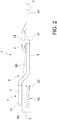
figure 2 shows a side view, with transparent parts, of the sole for footwear ofFigure 1 ;figure 3 illustrates a side-elevation perspective view, with transparent parts, of the sole for footwear offigure 1 lacking components; -
figure 4 is a side-elevation perspective view, with transparent parts, of the components housable in the sole ofFig. 3 ; -
figure 5 shows a side-elevation perspective view, with transparent parts, of part of the actuator group of the sole for footwear according to the present invention; -
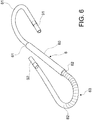
figure 6 illustrates a side-elevation perspective view, with transparent parts, of the energy harvester and of part of the actuator group of the sole for footwear according to the present invention; -
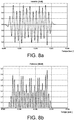
figure 7 is a plan view of the sole for footwear according to the present invention; andfigures 8a and 8b show the graphs of the course of the voltage and power recoverable by the sole according to the present invention during a strike of the foot. - With reference to the enclosed figures, it will be observed that a sole for footwear according to the present invention, in the illustrated case a left-shoe sole, is indicated overall with the
reference number 1 and has arear area 2, provided in use for the heel support, afront area 3, provided in use for the support of the front portion of the foot, anouter side portion 4 and aninner side portion 5. - The sole according to the present invention comprises at least one energy harvesting means 6, intended in use, as will be stated hereinbelow, to convert at least part of the energy produced during deambulation into electrical energy.
-
Such energy harvester 6 is, for example, of the type and illustrated inWO 2014/028799 (particular reference is made to theFig. 3 of such document) and comprises atubular body 60, fixed during use, having afirst end 61 and asecond end 62. - The
energy harvester 6 further comprises a movable part orbody 63, slidably inserted in thetubular body 60. The movable part orbody 63 of theharvester 6 is, as is known, composed of a plurality ofmagnets - The
energy harvester 6 is preferably housed in a central portion of the sole, at ahousing seat 45 provided for such purpose (seefigure 3 ). - More particularly, the
body 60 of theenergy harvester 6 extends longitudinally with itsfirst end 61 at an external lateral front area, and with the other end thereof, thesecond end 62, at an internal lateral rear area of the sole. - The sole according to the present invention further comprises at least one
actuator group 7 for operating theenergy harvester 6. - The
actuator group 7 comprises a fluid-dynamic circuit including at least onefirst fluid tank 71 in fluid communication with thefirst end 61 of thetubular body 60 of theenergy harvester 6 by means of a first joiningconduit 81. - The actuator group also comprises a
second fluid tank 72, placed in fluid communication with thesecond end 62 of thetubular body 60 of theenergy harvester 6 by means of a second joiningconduit 82. - As seen in
figures 1 and2 , themovable part 63 of theenergy harvester 6 has longitudinal extension greater than the longitudinal extension of thetubular body 60; in the case illustrated in the figures, such longitudinal extension is approximately double the tubular body, such that it is partially housed in the joiningconduits 81 and/or 82 of theactuator group 7. - The
movable part 63 of theenergy harvester 6 is provided, during use, slidable to fit in thetubular body 60 and in the joiningconduits actuator group 7, both towards thefirst tank 71 and towards thesecond tank 72. - Advantageously, the
first tank 71 of theactuator group 7 is housed at therear area 2 of the sole and has a configuration in plan view, which is substantially elongated and curved, U-shaped in the illustrated embodiment. More particularly,such tank 71 is arranged in therear area 2 of the sole in a manner so as to have ablind end 711 thereof at theouter side portion 4 of the sole and theother end 712 thereof for connection with thefirst end 61 of thetubular body 60 at aninner side portion 5 of the sole itself. The fluid connection between thefirst tank 71 and thefirst end 61 occurs by means of the first joiningconduit 81, connected to the tank by means of a fluid-seal connector 91. - The
second tank 72 of the sole according to the present invention is housed at thefront area 3 of the sole and has a configuration in plan view which is substantially elongated, and more particularly polygonal, rectangular or parallelogram in the illustrated example. Suchsecond tank 72 is housed in the sole transversely arranged in thefront area 3, in a manner so as to have ablind end 721 thereof at aninner side portion 5 of the sole, and theother end 722 thereof, for connection with thesecond end 62 of thetubular body 60 at anouter side portion 4 of said sole. Theblind end 721 of thetank 72 is more advanced in the sole with respect to theother end 722. - The fluid connection between the
second tank 72 and thesecond end 62 occurs by means of the second joiningconduit 82, connected to the tank by means of a fluid-seal connector 92. - In the shoe according to the present invention, the first and the
second tank - The joining
conduits front area 3 andrear area 2 of the sole, respectively. The joiningconduits - As stated above, the first and the second joining
conduit actuator group 7 are in fluid connection with the respective tanks by means ofseal conriectors movable body 63 of theenergy harvester 6. Themovable body 63 slides to size in theconduits - With one such configuration, it will be easily understood that, during deambulation, when the
first tank 71 is compressed due to the force exerted by the foot on the sole during the heel strike phase , the fluid F contained therein is effectively thrust towards theconnection end 712 of the tank and, by means of the joiningconduit 81, towards thefirst end 61 of the harvester. The fluid F in turn thrusts themovable body 63 in the harvester towards thesecond tank 72. - Conversely, when the force exerted by the foot on the sole passes from the
rear area 2 to thefront area 3 thereof, during the phase of strike of the front portion of the foot and before the lifting up of the foot from the ground, thesecond tank 72 is compressed and the fluid F contained therein is thrust to return towards theconnection end 722 of the tank itself and, by means of the joiningconduit 82, towards thesecond end 62 of thetubular body 60 of theharvester 6. The movement of the fluid F causes the sliding of themovable body 63 in theharvester 6 towards thefirst tank 71. - There is therefore generated a sliding in one direction and in the other of the
movable body 63 in thetubular body 60 of the harvester and this allows, in a known manner, described in the documentWO 2014/028799 , the generation of electrical energy according to the Faraday electromagnetic induction law. - The man skilled in the art will easily understand that the particular configuration of the first and
second tank 71 and 72 (more particularly of the first tank 71), their arrangement in the sole as well as the position of the respective fluid connection ends 712 and 722 allow optimizing the propulsive thrust of the fluid F inside theactuator group 7 during deambulation. As is known, during deambulation the foot first strikes against the external rear portion of the heel, after which it strikes against the central portion and front portion , along the so-called "pronation" line, which actually represents a kind of "S". - The arrangement of the
harvester 6 and of theactuator group 7 allows the fluid F to follow this S-like line, thus optimizing the thrust on the movable body of theharvester 6 and, accordingly, the conversion of such thrust into electrical energy. - Advantageously, the sole according to the present invention comprises a
bypass portion 10 for direct fluid communication between the first and thesecond tank -
Such bypass portion 10 acts as a group for regulating the pressures in the tanks. Indeed, it was verified that in some circumstances, although infrequently, the pressure exerted simultaneously on thefirst tank 71 and on thesecond tank 72 of theactuator group 7 is approximately the same in the same time interval, with the result that the fluid F contained in the tanks is substantially not moved between one tank and the other, and hence no thrust is generated on themovable body 63 of theenergy harvester 6. Therefore, the energy produced with the deambulation is not converted into electrical energy. - In order to overcome this situation and allow the sole according to the present invention to exploit, in any work condition, the energy produced with the deambulation by converting it into electrical energy, the bypass portion of the
actuator group 7 comprises at least onedelivery portion 101 and onereturn portion 102 between thetanks bypass portion 10 is advantageously provided between theconnection end 712 of thefirst tank 71 and a frontcentral portion 723 of thesecond tank 72. It is made of the same material used for thetanks - The
bypass portion 10 of the sole according to the present invention is provided for allowing the passage of fluid F therethrough only if the pressure is substantially equal between the tanks or is too high, e.g. higher than a predetermined threshold value, in one of the tanks. In normal work conditions of the sole, there is no passage of the fluid into the delivery and returnportions - The passage of fluid in the
bypass portion 10 allows regulating the quantity of fluid F between the tanks and the pressures involved, such that during deambulation themovable body 63 of theenergy harvester 6 is always moved by the fluid F with respect to the fixedbody 60 and the energy produced with the deambulation is always converted into electrical energy. - It will also be observed that with one such configuration of the
bypass portion 10, the risk of compromising the seal of the tanks and, therefore, the functionality of the system is drastically reduced. - The sole for footwear according to the present invention also comprises means for accumulating/dispensing 12 (see
figure 7 ) the electrical energy produced by theenergy harvester 6. Such accumulating/dispensing means are electrically connected to theenergy harvester 6 in a manner known for the man skilled in the art and allow delivering energy at variable frequency ranging from 0.1 to 1 KHz, low voltage and low output impedance, as illustrated by way of example inFigure 8 . The means are provided in the sole at therear portion 2, for example supported by the sole itself, as illustrated infigure 7 , housed in a respective housing seat obtained therein, for example below thefirst tank 71. - Such accumulating/dispensing 12 means are electrically connected to input/output means not illustrated in the drawings, for the connection of the sole to an electronic device.
- The input/output means can for example comprise a USB port, advantageously housed in a known manner in the sole or in another suitable place of the upper.
- The means for accumulating/dispensing 12 the electrical energy produced by the
energy harvester 6 can also be directly connected to consumer electronic devices (also not depicted in the drawings) that are also housed in the sole. Such devices can, for example, comprise a GPS or one or more accelerometers or one or more sensors or one or more SOCs (system on chip) or a MP3 player or possible combinations thereof, in turn connectable, preferably remotely, to auxiliary consumer electronic devices, such as one or more LED lights and/or a computer and/or a smart-phone and/or a smart-watch and/or, in the case of the MP3 player, wireless head-phones. - Now, returning to the means for accumulating/dispensing
energy 12 of the sole according to the present invention, according to one variant of the sole not illustrated in the drawings, in place of the energy harvesting means 6 a plurality of such energy harvesting means 6 are provided, arranged in series with each other and each electrically connected to the means for accumulating/dispensingenergy 12. - According to a further variant, also not illustrated in the drawings, the energy harvesting means 6 can comprise a plurality of tubular sections or segments, arranged in series with each other to form the
tubular body 60. The movable part orbody 63 is slidably inserted in such sections or segments, as described above. Each section or segment of the plurality of sections or segments is electrically connected to the means for accumulating/dispensingenergy 12. - In both variants, the means for accumulating/dispensing
energy 12 advantageously comprise a plurality of rectifier means, preferably of active type with MOS and comparator, each arranged downstream of arespective energy harvester 6 or section or segment thereof, in turn electrically controlled by a selector group or MUX. A possible charge pump switching regulator may be present downstream of the selector group, if the energy harvesting means 6 provide an electrical pulse with voltage, after rectification, e.g. less than about 3V. - This configuration allows maximizing the quantity of energy recovered from the deambulation, emitted by the
energy harvester 6 group. Experimental tests in fact demonstrate that, with one such configuration, it is possible to recover and make available approximately 80% of the energy delivered by eachenergy harvester 6. - The means for accumulating/dispensing
energy 12 further comprise accumulator means, electrically connected downstream of the selector group and possible regulator, and advantageously comprising a supercapacitor, in technical jargon termed "supercap", and a battery of the polymer/lithium ion type (or any other suitable type). - The supercapacitor acts as a buffer for the battery, mitigating the effects due to the high voltage and current peaks, and providing a very low input impedance, in a manner so as to quickly accumulate (much faster than the battery) current pulses that are even quite high (on the order of tens of Amperes), without losing significant energy. The "supercap" then provides the battery with the energy temporarily accumulated in a continuous manner and with limited currents (on the order of hundreds of mA).
- The accumulator means allow effectively accumulating the energy delivered by the energy harvesting means 6 and make it constantly available for an electronic device of the type mentioned above and in the requested voltage.
- It will be observed that the above-stated objects are attained with a sole for footwear as described above and, in particular, by the particular configuration of the
actuator group 7 and by its particular connection to theenergy harvester 6, of the type withmagnets - The above-described sole for footwear is susceptible of numerous modifications and variants within the protection scope of the following claims.
- Thus, for example, the sole according to the present invention has been described by taking under consideration a left shoe; of course, the present description holds true, mutatis mutandis, for a corresponding sole for a right shoe.
Claims (17)
- Sole for footwear capable of recovering part of the energy produced during deambulation comprising:- at least one energy harvesting means (6) comprising: one tubular body (60), fixed in use, having a first and a second end (61, 62); one movable part (63) slidable in said at least one tubular body (60); said at least one energy harvesting means (6) being designed, in use, for generating electric energy following the sliding of said movable part (63) with respect to said, fixed in use, tubular body (60), during said deambulation;- at least one actuator group (7) for said energy harvesting means (6), comprising at least one fluid-dynamic circuit including: at least one first and one second tank (71, 72) comprising a fluid (F), said at least one first tank (71) being housed at a rear area (2) of said sole, and said at least one second tank (72) being housed at a front area (3) of said sole; at least one first joining conduit (81) in fluid communication between said first tank (71) and said first end (61) of said at least one tubular body (60); said movable part (63) of said at least one energy harvesting means (6) being at least partially housed in said actuator group (7); and- at least means for accumulating/dispensing (12) said electric energy produced by said energy harvesting means (6), said accumulating/dispensing means being electrically connected to said at least one energy harvesting means (6); andcharacterized in that
the sole further comprises a second joining conduit (82) in fluid communication between
said second tank (72) and said second end (62) of said at least one tubular body (60);
said movable part (63) of said at least one energy harvesting means (6) is able to slide in both directions therein and in said tubular body (60), during said deambulation;
said at least one first tank (71) has a plant configuration which is substantially elongated and curved. - Sole according to claim 1, wherein said plant configuration of said at least one first tank (71) is U-shaped.
- Sole according to claim 2, wherein said first tank (71) with a substantially U-shaped configuration has a first end thereof which is blind (711), at a first outer side portion (4) of said sole, and the other end thereof (712), for connection to said first end (61) of said at least one tubular body (60), by means of said first joining conduit (81), at an inner side portion (5) of said sole.
- Sole according to any claim 1 to 3, wherein said at least one second tank (72) has a plant configuration which is substantially elongated.
- Sole according to claim 4, wherein said at least one second tank (72) with substantially elongated configuration is placed transversally in said front area (3) of said sole, so as to have one first blind end thereof (721), at an inner side portion (5) of said sole, and the other end thereof (722), for connection to said second end (62) of said at least one tubular body (60), by means of said second joining conduit (82), at an outer side portion (5) of said sole.
- Sole according to any claim 1 to 5, wherein said actuator group (7) comprises at least a bypass portion (10), for direct fluid communication between said first (71) and said second (72) tank, wherein said fluid (F) is designed to flow, when the pressure generated during deambulation in said tanks (71, 72) is substantially equal to or, in any of said tanks, greater than a predetermined threshold value.
- Sole according to claim 6, wherein said bypass portion (10) for direct fluid communication between said first (71) and said second (72) tank comprises at least a delivery portion (101) and a return portion (102) between said tanks, in each of said portions (101, 102) being fit inserted at least a valve member (11).
- Sole according to claim 7, wherein said valve member (11) is of the nonreturn type.
- Sole according to any claim 6 to 8, when depending on claim 3, wherein said bypass portion (10) for direct fluid communication between said first (71) and said second (72) tank is comprised between said end (712) for connection to said at least one first tank (71) and a front central portion (723) of said at least one second tank (72).
- Sole according to any claim 1 to 9, wherein said first and said second joining conduit (81, 82) are made of a rigid material.
- Sole according to any claim 1 to 10, wherein said first joining conduit (81) is housed at a front area (3) of said sole, and said second joining conduit (82) is housed at a rear area (2) of said sole.
- Sole according to any claim 1 to 11, wherein said accumulating/dispensing means (12) of said electric energy produced by said energy harvesting means (6) are housed at a rear area (2) of said sole, below said at least one first tank (71).
- Sole according to any claim 1 to 12, comprising at least input/output means operatively connected to said accumulating/dispensing means (12) for connecting said sole to at least one electronic device.
- Sole according to claim 13, wherein said input/output means comprise at least a USB-port.
- Sole according to any claim 1 to 14, wherein said accumulating/dispensing means (12) of said electric energy produced by said energy harvesting means (6) are directly connected to consumer electronic devices housed in the sole.
- Sole according to claim 15, wherein said consumer electronic devices comprise a GPS or one or more accelerometers or one or more sensors or one or more SOCs or a MP3 player or combinations thereof, which are in turn remote connectable to auxiliary consumer electronic devices.
- Sole according to claim 16, wherein said auxiliary consumer electronic devices comprise one or more LED lights and/or a computer and/or a smartphone and/or a smart-watch and/or wireless head-phones.
Applications Claiming Priority (2)
| Application Number | Priority Date | Filing Date | Title |
|---|---|---|---|
| ITVR20140127 | 2014-05-09 | ||
| PCT/IB2015/050777 WO2015170196A1 (en) | 2014-05-09 | 2015-02-02 | Sole for footwears capable of recovering part of the energy produced during deambulation |
Publications (2)
| Publication Number | Publication Date |
|---|---|
| EP3044460A1 EP3044460A1 (en) | 2016-07-20 |
| EP3044460B1 true EP3044460B1 (en) | 2018-01-10 |
Family
ID=51179083
Family Applications (1)
| Application Number | Title | Priority Date | Filing Date |
|---|---|---|---|
| EP15711824.1A Active EP3044460B1 (en) | 2014-05-09 | 2015-02-02 | Sole for footwears capable of recovering part of the energy produced during deambulation |
Country Status (7)
| Country | Link |
|---|---|
| US (1) | US9999273B2 (en) |
| EP (1) | EP3044460B1 (en) |
| JP (1) | JP6498277B2 (en) |
| CN (1) | CN105264226B (en) |
| CA (1) | CA2906332A1 (en) |
| RU (1) | RU2015149664A (en) |
| WO (1) | WO2015170196A1 (en) |
Families Citing this family (1)
| Publication number | Priority date | Publication date | Assignee | Title |
|---|---|---|---|---|
| KR102196189B1 (en) * | 2019-01-25 | 2020-12-30 | 한국신발피혁연구원 | Harvesting Apparatus for Shoes Improved Space Application |
Family Cites Families (24)
| Publication number | Priority date | Publication date | Assignee | Title |
|---|---|---|---|---|
| US3496871A (en) * | 1967-09-13 | 1970-02-24 | Entropy Ltd | Energy conversion device |
| US4175566A (en) * | 1975-08-07 | 1979-11-27 | Millar Instruments, Inc. | Catheter fluid-velocity flow probe |
| US4577417A (en) * | 1984-04-27 | 1986-03-25 | Energaire Corporation | Sole-and-heel structure having premolded bulges |
| CN87207729U (en) * | 1987-05-02 | 1988-01-13 | 袁鸣 | Electricity-generating shoes |
| US5483759A (en) * | 1994-02-01 | 1996-01-16 | Genesco Inc. | Footwear or other products |
| US6230501B1 (en) * | 1994-04-14 | 2001-05-15 | Promxd Technology, Inc. | Ergonomic systems and methods providing intelligent adaptive surfaces and temperature control |
| US5495682A (en) * | 1995-03-01 | 1996-03-05 | Chen; Shi-Hiu | Dynamoelectric shoes |
| US6201314B1 (en) * | 1998-04-28 | 2001-03-13 | Norman Landry | Shoe sole with liquid-powered electrical generator |
| CA2238592C (en) * | 1998-05-26 | 2005-07-05 | Robert Komarechka | Footwear with hydroelectric generator assembly |
| US6182378B1 (en) * | 1998-06-10 | 2001-02-06 | Musoke H. Sendaula | Low profile pneumatic electric generator integrated in a midsole of a shoe |
| DE10349357A1 (en) * | 2002-12-27 | 2004-07-08 | Werfel, Frank, Dr. | Mobile unit, e.g. contained in shoe heel, recovers energy and takes measurements using natural energy sources |
| US7446450B2 (en) * | 2004-06-07 | 2008-11-04 | California Institute Of Technology | Method and system using liquid dielectric for electrostatic power generation |
| TWI270243B (en) * | 2004-11-23 | 2007-01-01 | Ind Tech Res Inst | Device of micro vortex for ferro-fluid power generator |
| US7327046B2 (en) | 2005-12-23 | 2008-02-05 | Alexander Benjamin Biamonte | Kinetic energy system and apparatus for charging portable batteries |
| US7956476B2 (en) * | 2006-12-01 | 2011-06-07 | Honeywell International Inc. | Footwear energy harvesting system |
| US7898096B1 (en) * | 2007-08-22 | 2011-03-01 | Thomas Nikita Krupenkin | Method and apparatus for energy harvesting using microfluidics |
| TR200706912A2 (en) * | 2007-10-08 | 2009-02-23 | �Zt�Rk T�Rketap | A hydromechanical shoe. |
| TW200922487A (en) * | 2007-11-21 | 2009-06-01 | Yu-Tuan Lee | Shoe |
| US20100090477A1 (en) * | 2008-10-08 | 2010-04-15 | Keating Joseph A | Foot-Powered Footwear-Embedded Sensor-Transceiver |
| US9312792B2 (en) * | 2012-04-11 | 2016-04-12 | Thomas Nikita Krupenkin | Apparatus for closed-loop mechanical energy harvesting |
| US9109583B2 (en) * | 2012-08-17 | 2015-08-18 | Thomas Nikita Krupenkin | Apparatus for footwear-embedded mechanical energy harvesting using modular elements |
| US9259047B2 (en) * | 2012-09-13 | 2016-02-16 | Thomas Nikita Krupenkin | Apparatus for footwear-embedded mechanical energy harvesting system based on dual-loop channel |
| US9572393B2 (en) * | 2013-01-03 | 2017-02-21 | Thomas Nikita Krupenkin | Method and apparatus for providing internal heating of footwear |
| WO2014201356A1 (en) * | 2013-06-14 | 2014-12-18 | Sole Power, Llc | Energy storage system for foot-powered devices |
-
2015
- 2015-02-02 US US14/781,790 patent/US9999273B2/en not_active Expired - Fee Related
- 2015-02-02 RU RU2015149664A patent/RU2015149664A/en not_active Application Discontinuation
- 2015-02-02 CN CN201580000671.0A patent/CN105264226B/en not_active Expired - Fee Related
- 2015-02-02 CA CA2906332A patent/CA2906332A1/en not_active Abandoned
- 2015-02-02 JP JP2017510788A patent/JP6498277B2/en not_active Expired - Fee Related
- 2015-02-02 EP EP15711824.1A patent/EP3044460B1/en active Active
- 2015-02-02 WO PCT/IB2015/050777 patent/WO2015170196A1/en not_active Ceased
Also Published As
| Publication number | Publication date |
|---|---|
| JP6498277B2 (en) | 2019-04-10 |
| US9999273B2 (en) | 2018-06-19 |
| CN105264226B (en) | 2019-04-19 |
| RU2015149664A (en) | 2018-06-13 |
| CN105264226A (en) | 2016-01-20 |
| US20170042275A1 (en) | 2017-02-16 |
| WO2015170196A1 (en) | 2015-11-12 |
| EP3044460A1 (en) | 2016-07-20 |
| JP2017514662A (en) | 2017-06-08 |
| CA2906332A1 (en) | 2015-11-09 |
Similar Documents
| Publication | Publication Date | Title |
|---|---|---|
| US20140368157A1 (en) | Energy storage system for foot-powered devices | |
| CN204708093U (en) | A kind of multifunctional intellectual power-generating shoe | |
| US9999273B2 (en) | Sole for footwears capable of recovering part of the energy produced during deambulation | |
| CN201199991Y (en) | Automatic generating warm-keeping shoes | |
| CN104538937A (en) | Low-power protection apparatus of lithium ion battery | |
| CN105167308B (en) | A kind of footwear that can collect energy | |
| CN104161340A (en) | Walking power generation shoes for generating power through flowing liquid | |
| CN202233312U (en) | Luminous shoes | |
| CN202635763U (en) | Telescopic high-heeled shoe | |
| CN204409757U (en) | New type auto heating shoes | |
| CN106551462A (en) | A kind of damping charging shoes bottom | |
| CN205622277U (en) | Power supply circuit of portable equipment | |
| CN201247962Y (en) | Tri-stage intelligent charging module | |
| CN202077681U (en) | Composite slipper comfortable for wearing | |
| CN101263942A (en) | Sole | |
| CN105955009A (en) | Power supply circuit and intelligent bracelet of real-time clock | |
| CN204617194U (en) | Slippers used at night | |
| CN203445640U (en) | Independent photovoltaic system | |
| CN202145951U (en) | Novel anti-aging health care shoes | |
| CN201911397U (en) | Multifunctional heating shoes | |
| CN208522526U (en) | Power supply system is used in a kind of monitoring of Maple Syrup | |
| CN204861414U (en) | Cold -proof slippers | |
| CN205018385U (en) | Shoe with charging function | |
| CN201790077U (en) | Heating shoe outsoles | |
| CN204994737U (en) | Shock attenuation sole that charges |
Legal Events
| Date | Code | Title | Description |
|---|---|---|---|
| PUAI | Public reference made under article 153(3) epc to a published international application that has entered the european phase |
Free format text: ORIGINAL CODE: 0009012 |
|
| 17P | Request for examination filed |
Effective date: 20151223 |
|
| AK | Designated contracting states |
Kind code of ref document: A1 Designated state(s): AL AT BE BG CH CY CZ DE DK EE ES FI FR GB GR HR HU IE IS IT LI LT LU LV MC MK MT NL NO PL PT RO RS SE SI SK SM TR |
|
| AX | Request for extension of the european patent |
Extension state: BA ME |
|
| GRAP | Despatch of communication of intention to grant a patent |
Free format text: ORIGINAL CODE: EPIDOSNIGR1 |
|
| INTG | Intention to grant announced |
Effective date: 20170113 |
|
| RIN1 | Information on inventor provided before grant (corrected) |
Inventor name: MATTOLI, VIRGILIO Inventor name: TAYLOR, JOSEPH ASHLEY Inventor name: MONDINI, ALESSIO Inventor name: GRECO, FRANCESCO Inventor name: KRUPENKIN, TOM Inventor name: MAZZOLAI, BARBARA |
|
| GRAJ | Information related to disapproval of communication of intention to grant by the applicant or resumption of examination proceedings by the epo deleted |
Free format text: ORIGINAL CODE: EPIDOSDIGR1 |
|
| GRAJ | Information related to disapproval of communication of intention to grant by the applicant or resumption of examination proceedings by the epo deleted |
Free format text: ORIGINAL CODE: EPIDOSDIGR1 |
|
| GRAP | Despatch of communication of intention to grant a patent |
Free format text: ORIGINAL CODE: EPIDOSNIGR1 |
|
| INTC | Intention to grant announced (deleted) | ||
| GRAJ | Information related to disapproval of communication of intention to grant by the applicant or resumption of examination proceedings by the epo deleted |
Free format text: ORIGINAL CODE: EPIDOSDIGR1 |
|
| GRAP | Despatch of communication of intention to grant a patent |
Free format text: ORIGINAL CODE: EPIDOSNIGR1 |
|
| GRAP | Despatch of communication of intention to grant a patent |
Free format text: ORIGINAL CODE: EPIDOSNIGR1 |
|
| INTG | Intention to grant announced |
Effective date: 20170718 |
|
| GRAS | Grant fee paid |
Free format text: ORIGINAL CODE: EPIDOSNIGR3 |
|
| GRAA | (expected) grant |
Free format text: ORIGINAL CODE: 0009210 |
|
| AK | Designated contracting states |
Kind code of ref document: B1 Designated state(s): AL AT BE BG CH CY CZ DE DK EE ES FI FR GB GR HR HU IE IS IT LI LT LU LV MC MK MT NL NO PL PT RO RS SE SI SK SM TR |
|
| AX | Request for extension of the european patent |
Extension state: BA ME |
|
| REG | Reference to a national code |
Ref country code: CH Ref legal event code: EP Ref country code: AT Ref legal event code: REF Ref document number: 962711 Country of ref document: AT Kind code of ref document: T Effective date: 20180115 |
|
| REG | Reference to a national code |
Ref country code: IE Ref legal event code: FG4D |
|
| REG | Reference to a national code |
Ref country code: DE Ref legal event code: R096 Ref document number: 602015007357 Country of ref document: DE |
|
| REG | Reference to a national code |
Ref country code: NL Ref legal event code: MP Effective date: 20180110 |
|
| REG | Reference to a national code |
Ref country code: AT Ref legal event code: MK05 Ref document number: 962711 Country of ref document: AT Kind code of ref document: T Effective date: 20180110 |
|
| PG25 | Lapsed in a contracting state [announced via postgrant information from national office to epo] |
Ref country code: NL Free format text: LAPSE BECAUSE OF FAILURE TO SUBMIT A TRANSLATION OF THE DESCRIPTION OR TO PAY THE FEE WITHIN THE PRESCRIBED TIME-LIMIT Effective date: 20180110 |
|
| PG25 | Lapsed in a contracting state [announced via postgrant information from national office to epo] |
Ref country code: ES Free format text: LAPSE BECAUSE OF FAILURE TO SUBMIT A TRANSLATION OF THE DESCRIPTION OR TO PAY THE FEE WITHIN THE PRESCRIBED TIME-LIMIT Effective date: 20180110 Ref country code: CY Free format text: LAPSE BECAUSE OF FAILURE TO SUBMIT A TRANSLATION OF THE DESCRIPTION OR TO PAY THE FEE WITHIN THE PRESCRIBED TIME-LIMIT Effective date: 20180110 Ref country code: FI Free format text: LAPSE BECAUSE OF FAILURE TO SUBMIT A TRANSLATION OF THE DESCRIPTION OR TO PAY THE FEE WITHIN THE PRESCRIBED TIME-LIMIT Effective date: 20180110 Ref country code: LT Free format text: LAPSE BECAUSE OF FAILURE TO SUBMIT A TRANSLATION OF THE DESCRIPTION OR TO PAY THE FEE WITHIN THE PRESCRIBED TIME-LIMIT Effective date: 20180110 Ref country code: HR Free format text: LAPSE BECAUSE OF FAILURE TO SUBMIT A TRANSLATION OF THE DESCRIPTION OR TO PAY THE FEE WITHIN THE PRESCRIBED TIME-LIMIT Effective date: 20180110 Ref country code: NO Free format text: LAPSE BECAUSE OF FAILURE TO SUBMIT A TRANSLATION OF THE DESCRIPTION OR TO PAY THE FEE WITHIN THE PRESCRIBED TIME-LIMIT Effective date: 20180410 |
|
| PG25 | Lapsed in a contracting state [announced via postgrant information from national office to epo] |
Ref country code: BG Free format text: LAPSE BECAUSE OF FAILURE TO SUBMIT A TRANSLATION OF THE DESCRIPTION OR TO PAY THE FEE WITHIN THE PRESCRIBED TIME-LIMIT Effective date: 20180410 Ref country code: AT Free format text: LAPSE BECAUSE OF FAILURE TO SUBMIT A TRANSLATION OF THE DESCRIPTION OR TO PAY THE FEE WITHIN THE PRESCRIBED TIME-LIMIT Effective date: 20180110 Ref country code: PL Free format text: LAPSE BECAUSE OF FAILURE TO SUBMIT A TRANSLATION OF THE DESCRIPTION OR TO PAY THE FEE WITHIN THE PRESCRIBED TIME-LIMIT Effective date: 20180110 Ref country code: RS Free format text: LAPSE BECAUSE OF FAILURE TO SUBMIT A TRANSLATION OF THE DESCRIPTION OR TO PAY THE FEE WITHIN THE PRESCRIBED TIME-LIMIT Effective date: 20180110 Ref country code: IS Free format text: LAPSE BECAUSE OF FAILURE TO SUBMIT A TRANSLATION OF THE DESCRIPTION OR TO PAY THE FEE WITHIN THE PRESCRIBED TIME-LIMIT Effective date: 20180510 Ref country code: SE Free format text: LAPSE BECAUSE OF FAILURE TO SUBMIT A TRANSLATION OF THE DESCRIPTION OR TO PAY THE FEE WITHIN THE PRESCRIBED TIME-LIMIT Effective date: 20180110 Ref country code: LV Free format text: LAPSE BECAUSE OF FAILURE TO SUBMIT A TRANSLATION OF THE DESCRIPTION OR TO PAY THE FEE WITHIN THE PRESCRIBED TIME-LIMIT Effective date: 20180110 Ref country code: GR Free format text: LAPSE BECAUSE OF FAILURE TO SUBMIT A TRANSLATION OF THE DESCRIPTION OR TO PAY THE FEE WITHIN THE PRESCRIBED TIME-LIMIT Effective date: 20180411 |
|
| REG | Reference to a national code |
Ref country code: DE Ref legal event code: R119 Ref document number: 602015007357 Country of ref document: DE |
|
| REG | Reference to a national code |
Ref country code: CH Ref legal event code: PL |
|
| PG25 | Lapsed in a contracting state [announced via postgrant information from national office to epo] |
Ref country code: RO Free format text: LAPSE BECAUSE OF FAILURE TO SUBMIT A TRANSLATION OF THE DESCRIPTION OR TO PAY THE FEE WITHIN THE PRESCRIBED TIME-LIMIT Effective date: 20180110 Ref country code: AL Free format text: LAPSE BECAUSE OF FAILURE TO SUBMIT A TRANSLATION OF THE DESCRIPTION OR TO PAY THE FEE WITHIN THE PRESCRIBED TIME-LIMIT Effective date: 20180110 Ref country code: MC Free format text: LAPSE BECAUSE OF FAILURE TO SUBMIT A TRANSLATION OF THE DESCRIPTION OR TO PAY THE FEE WITHIN THE PRESCRIBED TIME-LIMIT Effective date: 20180110 Ref country code: EE Free format text: LAPSE BECAUSE OF FAILURE TO SUBMIT A TRANSLATION OF THE DESCRIPTION OR TO PAY THE FEE WITHIN THE PRESCRIBED TIME-LIMIT Effective date: 20180110 |
|
| PLBE | No opposition filed within time limit |
Free format text: ORIGINAL CODE: 0009261 |
|
| STAA | Information on the status of an ep patent application or granted ep patent |
Free format text: STATUS: NO OPPOSITION FILED WITHIN TIME LIMIT |
|
| REG | Reference to a national code |
Ref country code: IE Ref legal event code: MM4A |
|
| REG | Reference to a national code |
Ref country code: BE Ref legal event code: MM Effective date: 20180228 |
|
| PG25 | Lapsed in a contracting state [announced via postgrant information from national office to epo] |
Ref country code: LI Free format text: LAPSE BECAUSE OF NON-PAYMENT OF DUE FEES Effective date: 20180228 Ref country code: LU Free format text: LAPSE BECAUSE OF NON-PAYMENT OF DUE FEES Effective date: 20180202 Ref country code: CH Free format text: LAPSE BECAUSE OF NON-PAYMENT OF DUE FEES Effective date: 20180228 Ref country code: SM Free format text: LAPSE BECAUSE OF FAILURE TO SUBMIT A TRANSLATION OF THE DESCRIPTION OR TO PAY THE FEE WITHIN THE PRESCRIBED TIME-LIMIT Effective date: 20180110 Ref country code: DK Free format text: LAPSE BECAUSE OF FAILURE TO SUBMIT A TRANSLATION OF THE DESCRIPTION OR TO PAY THE FEE WITHIN THE PRESCRIBED TIME-LIMIT Effective date: 20180110 Ref country code: CZ Free format text: LAPSE BECAUSE OF FAILURE TO SUBMIT A TRANSLATION OF THE DESCRIPTION OR TO PAY THE FEE WITHIN THE PRESCRIBED TIME-LIMIT Effective date: 20180110 Ref country code: SK Free format text: LAPSE BECAUSE OF FAILURE TO SUBMIT A TRANSLATION OF THE DESCRIPTION OR TO PAY THE FEE WITHIN THE PRESCRIBED TIME-LIMIT Effective date: 20180110 |
|
| REG | Reference to a national code |
Ref country code: FR Ref legal event code: ST Effective date: 20181031 |
|
| 26N | No opposition filed |
Effective date: 20181011 |
|
| PG25 | Lapsed in a contracting state [announced via postgrant information from national office to epo] |
Ref country code: IE Free format text: LAPSE BECAUSE OF NON-PAYMENT OF DUE FEES Effective date: 20180202 Ref country code: DE Free format text: LAPSE BECAUSE OF NON-PAYMENT OF DUE FEES Effective date: 20180901 |
|
| PG25 | Lapsed in a contracting state [announced via postgrant information from national office to epo] |
Ref country code: BE Free format text: LAPSE BECAUSE OF NON-PAYMENT OF DUE FEES Effective date: 20180228 Ref country code: FR Free format text: LAPSE BECAUSE OF NON-PAYMENT OF DUE FEES Effective date: 20180312 Ref country code: SI Free format text: LAPSE BECAUSE OF FAILURE TO SUBMIT A TRANSLATION OF THE DESCRIPTION OR TO PAY THE FEE WITHIN THE PRESCRIBED TIME-LIMIT Effective date: 20180110 |
|
| GBPC | Gb: european patent ceased through non-payment of renewal fee |
Effective date: 20190202 |
|
| PG25 | Lapsed in a contracting state [announced via postgrant information from national office to epo] |
Ref country code: GB Free format text: LAPSE BECAUSE OF NON-PAYMENT OF DUE FEES Effective date: 20190202 Ref country code: MT Free format text: LAPSE BECAUSE OF NON-PAYMENT OF DUE FEES Effective date: 20180202 |
|
| PG25 | Lapsed in a contracting state [announced via postgrant information from national office to epo] |
Ref country code: TR Free format text: LAPSE BECAUSE OF FAILURE TO SUBMIT A TRANSLATION OF THE DESCRIPTION OR TO PAY THE FEE WITHIN THE PRESCRIBED TIME-LIMIT Effective date: 20180110 |
|
| PG25 | Lapsed in a contracting state [announced via postgrant information from national office to epo] |
Ref country code: PT Free format text: LAPSE BECAUSE OF FAILURE TO SUBMIT A TRANSLATION OF THE DESCRIPTION OR TO PAY THE FEE WITHIN THE PRESCRIBED TIME-LIMIT Effective date: 20180110 |
|
| PG25 | Lapsed in a contracting state [announced via postgrant information from national office to epo] |
Ref country code: HU Free format text: LAPSE BECAUSE OF FAILURE TO SUBMIT A TRANSLATION OF THE DESCRIPTION OR TO PAY THE FEE WITHIN THE PRESCRIBED TIME-LIMIT; INVALID AB INITIO Effective date: 20150202 Ref country code: MK Free format text: LAPSE BECAUSE OF NON-PAYMENT OF DUE FEES Effective date: 20180110 |
|
| PGFP | Annual fee paid to national office [announced via postgrant information from national office to epo] |
Ref country code: IT Payment date: 20221027 Year of fee payment: 9 |
|
| P01 | Opt-out of the competence of the unified patent court (upc) registered |
Effective date: 20230509 |
|
| PG25 | Lapsed in a contracting state [announced via postgrant information from national office to epo] |
Ref country code: IT Free format text: LAPSE BECAUSE OF NON-PAYMENT OF DUE FEES Effective date: 20240202 |