EP3044417B1 - Fan blades and manufacture methods - Google Patents
Fan blades and manufacture methods Download PDFInfo
- Publication number
- EP3044417B1 EP3044417B1 EP14860986.0A EP14860986A EP3044417B1 EP 3044417 B1 EP3044417 B1 EP 3044417B1 EP 14860986 A EP14860986 A EP 14860986A EP 3044417 B1 EP3044417 B1 EP 3044417B1
- Authority
- EP
- European Patent Office
- Prior art keywords
- spacer
- substrate
- scrim
- sheath
- airfoil member
- Prior art date
- Legal status (The legal status is an assumption and is not a legal conclusion. Google has not performed a legal analysis and makes no representation as to the accuracy of the status listed.)
- Active
Links
Images



Classifications
-
- F—MECHANICAL ENGINEERING; LIGHTING; HEATING; WEAPONS; BLASTING
- F01—MACHINES OR ENGINES IN GENERAL; ENGINE PLANTS IN GENERAL; STEAM ENGINES
- F01D—NON-POSITIVE DISPLACEMENT MACHINES OR ENGINES, e.g. STEAM TURBINES
- F01D5/00—Blades; Blade-carrying members; Heating, heat-insulating, cooling or antivibration means on the blades or the members
- F01D5/12—Blades
- F01D5/28—Selecting particular materials; Particular measures relating thereto; Measures against erosion or corrosion
- F01D5/288—Protective coatings for blades
-
- F—MECHANICAL ENGINEERING; LIGHTING; HEATING; WEAPONS; BLASTING
- F04—POSITIVE - DISPLACEMENT MACHINES FOR LIQUIDS; PUMPS FOR LIQUIDS OR ELASTIC FLUIDS
- F04D—NON-POSITIVE-DISPLACEMENT PUMPS
- F04D29/00—Details, component parts, or accessories
- F04D29/02—Selection of particular materials
- F04D29/023—Selection of particular materials especially adapted for elastic fluid pumps
-
- F—MECHANICAL ENGINEERING; LIGHTING; HEATING; WEAPONS; BLASTING
- F04—POSITIVE - DISPLACEMENT MACHINES FOR LIQUIDS; PUMPS FOR LIQUIDS OR ELASTIC FLUIDS
- F04D—NON-POSITIVE-DISPLACEMENT PUMPS
- F04D29/00—Details, component parts, or accessories
- F04D29/26—Rotors specially for elastic fluids
- F04D29/32—Rotors specially for elastic fluids for axial flow pumps
- F04D29/321—Rotors specially for elastic fluids for axial flow pumps for axial flow compressors
- F04D29/324—Blades
-
- F—MECHANICAL ENGINEERING; LIGHTING; HEATING; WEAPONS; BLASTING
- F04—POSITIVE - DISPLACEMENT MACHINES FOR LIQUIDS; PUMPS FOR LIQUIDS OR ELASTIC FLUIDS
- F04D—NON-POSITIVE-DISPLACEMENT PUMPS
- F04D29/00—Details, component parts, or accessories
- F04D29/26—Rotors specially for elastic fluids
- F04D29/32—Rotors specially for elastic fluids for axial flow pumps
- F04D29/325—Rotors specially for elastic fluids for axial flow pumps for axial flow fans
-
- F—MECHANICAL ENGINEERING; LIGHTING; HEATING; WEAPONS; BLASTING
- F04—POSITIVE - DISPLACEMENT MACHINES FOR LIQUIDS; PUMPS FOR LIQUIDS OR ELASTIC FLUIDS
- F04D—NON-POSITIVE-DISPLACEMENT PUMPS
- F04D29/00—Details, component parts, or accessories
- F04D29/26—Rotors specially for elastic fluids
- F04D29/32—Rotors specially for elastic fluids for axial flow pumps
- F04D29/38—Blades
- F04D29/388—Blades characterised by construction
-
- F—MECHANICAL ENGINEERING; LIGHTING; HEATING; WEAPONS; BLASTING
- F04—POSITIVE - DISPLACEMENT MACHINES FOR LIQUIDS; PUMPS FOR LIQUIDS OR ELASTIC FLUIDS
- F04D—NON-POSITIVE-DISPLACEMENT PUMPS
- F04D29/00—Details, component parts, or accessories
- F04D29/60—Mounting; Assembling; Disassembling
- F04D29/64—Mounting; Assembling; Disassembling of axial pumps
- F04D29/644—Mounting; Assembling; Disassembling of axial pumps especially adapted for elastic fluid pumps
-
- F—MECHANICAL ENGINEERING; LIGHTING; HEATING; WEAPONS; BLASTING
- F05—INDEXING SCHEMES RELATING TO ENGINES OR PUMPS IN VARIOUS SUBCLASSES OF CLASSES F01-F04
- F05D—INDEXING SCHEME FOR ASPECTS RELATING TO NON-POSITIVE-DISPLACEMENT MACHINES OR ENGINES, GAS-TURBINES OR JET-PROPULSION PLANTS
- F05D2240/00—Components
- F05D2240/20—Rotors
- F05D2240/30—Characteristics of rotor blades, i.e. of any element transforming dynamic fluid energy to or from rotational energy and being attached to a rotor
- F05D2240/303—Characteristics of rotor blades, i.e. of any element transforming dynamic fluid energy to or from rotational energy and being attached to a rotor related to the leading edge of a rotor blade
-
- F—MECHANICAL ENGINEERING; LIGHTING; HEATING; WEAPONS; BLASTING
- F05—INDEXING SCHEMES RELATING TO ENGINES OR PUMPS IN VARIOUS SUBCLASSES OF CLASSES F01-F04
- F05D—INDEXING SCHEME FOR ASPECTS RELATING TO NON-POSITIVE-DISPLACEMENT MACHINES OR ENGINES, GAS-TURBINES OR JET-PROPULSION PLANTS
- F05D2300/00—Materials; Properties thereof
- F05D2300/10—Metals, alloys or intermetallic compounds
- F05D2300/17—Alloys
- F05D2300/173—Aluminium alloys, e.g. AlCuMgPb
-
- F—MECHANICAL ENGINEERING; LIGHTING; HEATING; WEAPONS; BLASTING
- F05—INDEXING SCHEMES RELATING TO ENGINES OR PUMPS IN VARIOUS SUBCLASSES OF CLASSES F01-F04
- F05D—INDEXING SCHEME FOR ASPECTS RELATING TO NON-POSITIVE-DISPLACEMENT MACHINES OR ENGINES, GAS-TURBINES OR JET-PROPULSION PLANTS
- F05D2300/00—Materials; Properties thereof
- F05D2300/10—Metals, alloys or intermetallic compounds
- F05D2300/17—Alloys
- F05D2300/174—Titanium alloys, e.g. TiAl
-
- F—MECHANICAL ENGINEERING; LIGHTING; HEATING; WEAPONS; BLASTING
- F05—INDEXING SCHEMES RELATING TO ENGINES OR PUMPS IN VARIOUS SUBCLASSES OF CLASSES F01-F04
- F05D—INDEXING SCHEME FOR ASPECTS RELATING TO NON-POSITIVE-DISPLACEMENT MACHINES OR ENGINES, GAS-TURBINES OR JET-PROPULSION PLANTS
- F05D2300/00—Materials; Properties thereof
- F05D2300/60—Properties or characteristics given to material by treatment or manufacturing
- F05D2300/603—Composites; e.g. fibre-reinforced
- F05D2300/6033—Ceramic matrix composites [CMC]
Definitions
- the disclosure relates to turbine engine. More particularly, the disclosure relates to bonding galvanically dissimilar sheaths and substrates.
- a protective sheath is used to protect a substrate or main body of the component.
- Such sheaths may offer protection from foreign object damage or wear to leading edge and/or trailing edge portions of airfoils.
- the sheath forms a limited portion of the airfoil contour with the main body providing the rest.
- the sheath may be of a more expensive material than the main body (e.g., a titanium alloy sheath on an aluminum alloy body where the aluminum alloy is used for cost reasons). In others, the sheath may be of a less expensive material (e.g., when the body is of a very light material with little impact resistance (e.g., a carbon fiber composite)).
- US patent application publications 20110211967 and 20120301292 disclose a sheath bonded to blade substrate using a scrim and epoxy.
- the scrim and epoxy may galvanically isolate the sheath from the substrate to prevent corrosion.
- EP 2362067 A2 (the European equivalent to US patent application publication 20110211967 ) and EP 2540978 A2 disclose airflow members having the features of the preamble of claim 1.
- the present invention provides an airfoil member as set forth in claim 1.
- An embodiment may include the airfoil member being a blade.
- a further embodiment may additionally and/or alternatively include the spacer being between the scrim and the substrate.
- a further embodiment may additionally and/or alternatively include: the substrate being a first metallic material; and the sheath being a second metallic material different from the first metallic material.
- a further embodiment may additionally and/or alternatively include: the first metallic material being an aluminum alloy; and the second metallic material being a titanium alloy.
- a further embodiment may additionally and/or alternatively include the scrim comprising glass fiber mesh.
- a further embodiment may additionally and/or alternatively include the scrim has only a single mesh layer.
- a further embodiment may additionally and/or alternatively include the spacer comprising a fibrous sheet.
- a further embodiment may additionally and/or alternatively include the spacer comprising glass fiber.
- a further embodiment may additionally and/or alternatively include the glass fiber being formed as a woven sheet.
- a further embodiment may additionally and/or alternatively include the spacer comprising: a spine having a first edge and a second edge; a plurality of first arms extending from the first edge; and a plurality of second arms extending from the second edge.
- a further embodiment may additionally and/or alternatively include: the spine being between a base of the channel and an edge of the received portion of the substrate; the first arms extending downstream from the spine along a pressure side of the received portion; and the second arms extending downstream from the spine along a suction side of the received portion.
- a further embodiment may additionally and/or alternatively include the spacer having a characteristic thickness of 0.15mm to 0.40 mm; and the scrim having a characteristic thickness of 0.05 mm to 0.15 mm.
- a further embodiment may additionally and/or alternatively include the airfoil member being a fan blade.
- a further embodiment may additionally and/or alternatively include the sheath forming a leading edge of the airfoil.
- the invention also provides a method for manufacturing the blade, as set forth in claim 13.
- An embodiment may include the spacer being applied as a prepreg.
- a further embodiment may additionally and/or alternatively include the prepreg. being an epoxy prepreg.
- a further embodiment may additionally and/or alternatively include the applying of the sheath leaving end portions of the spaced-apart portions protruding along the substrate.
- a further embodiment may additionally and/or alternatively include cutting off the end portions.
- a further embodiment may additionally and/or alternatively include applying an adhesive to secure the scrim to the substrate and applying an adhesive to secure the sheath to the scrim.
- a further embodiment may additionally and/or alternatively include a turbine engine comprising the airfoil member as a fan blade.
- a further embodiment may additionally and/or alternatively include the sheath forming a leading edge of the airfoil.
- FIG. 1 shows a gas turbine engine 20 having an engine case 22 surrounding a centerline or central longitudinal axis 500.
- An exemplary gas turbine engine is a turbofan engine having a fan section 24 including a fan 26 within a fan case 28.
- the exemplary engine includes an inlet 30 at an upstream end of the fan case receiving an inlet flow along an inlet flowpath 520.
- the fan 26 has one or more stages 32 of fan blades. Downstream of the fan blades, the flowpath 520 splits into an inboard portion 522 being a core flowpath and passing through a core of the engine and an outboard portion 524 being a bypass flowpath exiting an outlet 34 of the fan case.
- the core flowpath 522 proceeds downstream to an engine outlet 36 through one or more compressor sections, a combustor, and one or more turbine sections.
- the exemplary engine has two axial compressor sections and two axial turbine sections, although other configurations are equally applicable.
- LPC low pressure compressor section
- HPC high pressure compressor section
- HPT high pressure turbine section
- LPT low pressure turbine section
- Each of the LPC, HPC, HPT, and LPT comprises one or more stages of blades which may be interspersed with one or more stages of stator vanes.
- the blade stages of the LPC and LPT are part of a low pressure spool mounted for rotation about the axis 500.
- the exemplary low pressure spool includes a shaft (low pressure shaft) 50 which couples the blade stages of the LPT to those of the LPC and allows the LPT to drive rotation of the LPC.
- the shaft 50 also drives the fan.
- the fan is driven via a transmission (not shown, e.g., a fan gear drive system such as an epicyclic transmission) to allow the fan to rotate at a lower speed than the low pressure shaft.
- the exemplary engine further includes a high pressure shaft 52 mounted for rotation about the axis 500 and coupling the blade stages of the HPT to those of the HPC to allow the HPT to drive rotation of the HPC.
- a high pressure shaft 52 mounted for rotation about the axis 500 and coupling the blade stages of the HPT to those of the HPC to allow the HPT to drive rotation of the HPC.
- fuel is introduced to compressed air from the HPC and combusted to produce a high pressure gas which, in turn, is expanded in the turbine sections to extract energy and drive rotation of the respective turbine sections and their associated compressor sections (to provide the compressed air to the combustor) and fan.
- FIG. 2 shows a fan blade 100.
- the blade has an airfoil 102 extending spanwise outward from an inboard end 104 at a platform 105 or an attachment root 106 to a tip 108 (e.g., an unshrouded or "free" tip).
- the airfoil has a leading edge 110, trailing edge 112, pressure side 114 ( FIG. 3 ) and suction side 116.
- a metallic member forms a main body 120 of the airfoil and overall blade to which a leading edge sheath 122 is secured.
- Exemplary main bodies 120 are aluminum-based and exemplary leading edge sheathes are titanium-based. Such materials are disclosed in US patent application publications 20110211967 and 20120301292 .
- Alternative main body materials include carbon fiber composites.
- Other airfoil articles include other cold section components of the engine including fan inlet guide vanes, fan exit guide vanes, compressor blades, and compressor vanes or other cold section vanes or struts.
- FIG. 3 is a sectional view of a leading portion of the airfoil of the blade of FIG. 2 .
- the sheath 122 is formed as a channel structure having portions 140 and 142 respectively along the pressure side and suction side.
- the portions 140 and 142 are on opposite sides of a channel 144 formed by an inner surface 146 of the sheath and extending downstream from a base 148.
- the portions 140 and 142 respectively extend downstream to downstream edges 150 and 152.
- the sheath 122 in its channel 144, receives a leading portion 160 of the main body 120.
- the exemplary leading portion 160 extends downstream from a leading edge 162 to respective pressure side and suction side shoulders 164 and 166.
- the shoulders separate the leading portion from respective portions of the airfoil pressure and suction side surfaces along the main body 120.
- a scrim 200 ( FIGS. 4 and 5 ) separates the leading portion 160 from the sheath inner surface 146.
- An additional isolating member is formed by a spacer 220.
- the planform of the scrim covers essentially the entire planform of the joint along the sheath channel 144
- the exemplary spacer has more limited planform.
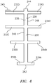
- the spacer shown in pre-installation planform in FIG. 6 ) has a spine or trunk 230 and a plurality of arms or branches 232, 234 extending from the spine. Inboard surface/face 236 and outboard surface/face 238 are shown.
- the spine is positioned between the leading edge 162 of leading portion 160 and the channel base 148.
- the exemplary arms 232 and 234 respectively extend downstream along the pressure side and suction side of the leading portion. End portions 240 of the arms (ultimately cut off) extend during manufacture along the pressure side and suction side of the main body downstream from the respective shoulders.
- the spacer spine 230 (shown in pre-installation planform in FIG. 6 ) extends from an inboard end 242 to an outboard end 244 and has respective first and second edges 246 and 248 from which the arms extend.
- FIG. 6 subnumbers the arms 232 as 232A, 232B, 232C and 232D and the arms 234 as 234A, 234B, 234C and 234D from inboard to outboard.
- four arms per side are shown, there need not be the same arm count on each side and different numbers of arms may be used.
- Exemplary arm count is 2-10 per side, more narrowly 3-6.
- Exemplary spacer coverage is less than 50% of the planform of the joint.
- the spine may directly act as a shield/barrier to penetration by burrs or other defects in the metal of either the sheath or main body.
- the spacer may be formed of a denser, less open material than the scrim (e.g., a tightly woven fabric versus an open mesh scrim having a greater fraction of open area).
- the fabric of the spacer may have an open area fraction less than half the open area fraction of the mesh of the scrim, more narrowly less than 20% or even zero.
- the spacer may be thicker than the scrim, for example, the thickness of the spacer fabric may be at least 150% of the thickness of the mesh, more particularly 150% to 1000% or 150% to 400%.
- the spacing function alone helps provide isolation (e.g., allowing for a relatively thick epoxy layer in the gaps between arms).
- the skeletal structure offers ease of manufacture relative to a hypothetical variation having a dense spacer completely filling the joint planform (e.g., by reducing or eliminating any bunching, etc.).
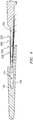
- FIG. 4 shows an exploded view reflecting a manufacturing process utilizing pre-formed adhesive films 280 and 282.
- Film 280 secures the scrim to the spacer and directly to the substrate in the gaps between spacer arms.
- Film 282 secures the sheath to the spacer.
- the adhesives e.g., the epoxy of the prepreg. spacer and the films 280, 282 may integrate and lose any distinctions. Other adhesive application techniques are possible.
- Exemplary spacer 220 material is a woven fiberglass fabric.
- Exemplary fabric is AMS 3824, style 7781 available from BGF Industries, Inc., Greensboro, North Carolina.
- the material may be preimpregnated with an epoxy resin to form a prepreg.
- Exemplary resin is CYCOMTM 306 of Cytec Industries Inc., Woodland Hills, New Jersey.
- the prepreg. may be cut to shape.
- Exemplary thickness of the spacer fabric prior to preimpregnation is 0.009 inch (0.23 mm).
- Exemplary thickness of the preimpregnated spacer is 0.013 inch (0.33 mm).
- a broader exemplary range of fabric thickness (approximating scrim thickness in the final composite) is 0.15 mm to 0.40 mm, more broadly 0.10 mm to 0.60 mm.
- Exemplary scrim 200 material is a woven fiberglass mesh.
- An exemplary mesh is prefinished with a coupling agent finish.
- Exemplary mesh is style 1659 with a 550 finish of BGF Industries, Inc., Greensboro, North Carolina.
- Exemplary thickness of the scrim with finish is 0.004 inch (0.1 mm).
- a broader exemplary range of mesh thickness (approximating its thickness in the final composite) is 0.05 mm to 0.15 mm, more broadly 0.03 mm to 0.20 mm.
- Exemplary adhesive film 280, 282 is an unsupported thermosetting, modified epoxy adhesive film such as 3MTM Scotch-WeldTM structural adhesive film AF 3109-2U of 3M, St. Paul, Minnesota. Exemplary initial film thickness is 0.005 inch (0.013mm).
- the first step is applying the precut spacer prepreg. 220 to the substrate.
- the end portions 240 may be taped to the substrate.
- the film 280 is applied.
- scrim 200 is applied without epoxy.
- film 282 is applied.
- the sheath is applied.
- the assembly is then shrink wrapped to compress.
- the wrapped assembly is then bagged and autoclaved to cure. After autoclaving the assembly is debagged/dewrapped and cleaned. Any flash may be removed and the protruding tabs 240 cut away.
- the additional use of the spacer may improve galvanic isolation while not substantially adversely affecting sheath adhesion, precision of sheath mounting, rigidity of sheath mounting, and the like.
- first, second, and the like in the following claims is for differentiation within the claim only and does not necessarily indicate relative or absolute importance or temporal order. Similarly, the identification in a claim of one element as “first” (or the like) does not preclude such "first” element from identifying an element that is referred to as “second” (or the like) in another claim or in the description.
Landscapes
- Engineering & Computer Science (AREA)
- Mechanical Engineering (AREA)
- General Engineering & Computer Science (AREA)
- Chemical & Material Sciences (AREA)
- Materials Engineering (AREA)
- Structures Of Non-Positive Displacement Pumps (AREA)
Description
- The disclosure relates to turbine engine. More particularly, the disclosure relates to bonding galvanically dissimilar sheaths and substrates.
- In a number of situations in gas turbine engine cold section components such as blades and vanes, a protective sheath is used to protect a substrate or main body of the component. Such sheaths may offer protection from foreign object damage or wear to leading edge and/or trailing edge portions of airfoils. In such situations, the sheath forms a limited portion of the airfoil contour with the main body providing the rest.
- In some examples, the sheath may be of a more expensive material than the main body (e.g., a titanium alloy sheath on an aluminum alloy body where the aluminum alloy is used for cost reasons). In others, the sheath may be of a less expensive material (e.g., when the body is of a very light material with little impact resistance (e.g., a carbon fiber composite)).
-
US patent application publications 20110211967 and20120301292 disclose a sheath bonded to blade substrate using a scrim and epoxy. The scrim and epoxy may galvanically isolate the sheath from the substrate to prevent corrosion. -
EP 2362067 A2 (the European equivalent toUS patent application publication 20110211967 ) andEP 2540978 A2 disclose airflow members having the features of the preamble of claim 1. - The present invention provides an airfoil member as set forth in claim 1.
- An embodiment may include the airfoil member being a blade.
- A further embodiment may additionally and/or alternatively include the spacer being between the scrim and the substrate.
- A further embodiment may additionally and/or alternatively include: the substrate being a first metallic material; and the sheath being a second metallic material different from the first metallic material.
- A further embodiment may additionally and/or alternatively include: the first metallic material being an aluminum alloy; and the second metallic material being a titanium alloy.
- A further embodiment may additionally and/or alternatively include the scrim comprising glass fiber mesh.
- A further embodiment may additionally and/or alternatively include the scrim has only a single mesh layer.
- A further embodiment may additionally and/or alternatively include the spacer comprising a fibrous sheet.
- A further embodiment may additionally and/or alternatively include the spacer comprising glass fiber.
- A further embodiment may additionally and/or alternatively include the glass fiber being formed as a woven sheet.
- A further embodiment may additionally and/or alternatively include the spacer comprising: a spine having a first edge and a second edge; a plurality of first arms extending from the first edge; and a plurality of second arms extending from the second edge.
- A further embodiment may additionally and/or alternatively include: the spine being between a base of the channel and an edge of the received portion of the substrate; the first arms extending downstream from the spine along a pressure side of the received portion; and the second arms extending downstream from the spine along a suction side of the received portion.
- A further embodiment may additionally and/or alternatively include the spacer having a characteristic thickness of 0.15mm to 0.40 mm; and the scrim having a characteristic thickness of 0.05 mm to 0.15 mm.
- A further embodiment may additionally and/or alternatively include the airfoil member being a fan blade.
- A further embodiment may additionally and/or alternatively include the sheath forming a leading edge of the airfoil.
- The invention also provides a method for manufacturing the blade, as set forth in claim 13.
- An embodiment may include the spacer being applied as a prepreg.
- A further embodiment may additionally and/or alternatively include the prepreg. being an epoxy prepreg.
- A further embodiment may additionally and/or alternatively include the applying of the sheath leaving end portions of the spaced-apart portions protruding along the substrate.
- A further embodiment may additionally and/or alternatively include cutting off the end portions.
- A further embodiment may additionally and/or alternatively include applying an adhesive to secure the scrim to the substrate and applying an adhesive to secure the sheath to the scrim.
- A further embodiment may additionally and/or alternatively include a turbine engine comprising the airfoil member as a fan blade.
- A further embodiment may additionally and/or alternatively include the sheath forming a leading edge of the airfoil.
- The details of one or more embodiments are set forth in the accompanying drawings and the description below. Other features, objects, and advantages will be apparent from the description and drawings, and from the claims.
-
-
FIG. 1 is a partially schematic half-sectional view of a turbofan engine. -
FIG. 2 is a view of a fan blade of the engine ofFIG. 1 . -
FIG. 3 is a partial sectional view of the blade ofFIG. 2 , taken along line 3-3. -
FIG. 4 is an exploded sectional view of the blade ofFIG. 3 showing manufacturing features. -
FIG. 5 is a cutaway view of the blade ofFIG. 2 . -
FIG. 6 is a plan view of a spacer before installation. - Like reference numbers and designations in the various drawings indicate like elements.
-
FIG. 1 shows agas turbine engine 20 having anengine case 22 surrounding a centerline or centrallongitudinal axis 500. An exemplary gas turbine engine is a turbofan engine having afan section 24 including afan 26 within afan case 28. The exemplary engine includes aninlet 30 at an upstream end of the fan case receiving an inlet flow along aninlet flowpath 520. Thefan 26 has one ormore stages 32 of fan blades. Downstream of the fan blades, theflowpath 520 splits into aninboard portion 522 being a core flowpath and passing through a core of the engine and anoutboard portion 524 being a bypass flowpath exiting anoutlet 34 of the fan case. - The
core flowpath 522 proceeds downstream to anengine outlet 36 through one or more compressor sections, a combustor, and one or more turbine sections. The exemplary engine has two axial compressor sections and two axial turbine sections, although other configurations are equally applicable. From upstream to downstream there is a low pressure compressor section (LPC) 40, a high pressure compressor section (HPC) 42, acombustor section 44, a high pressure turbine section (HPT) 46, and a low pressure turbine section (LPT) 48. Each of the LPC, HPC, HPT, and LPT comprises one or more stages of blades which may be interspersed with one or more stages of stator vanes. - In the exemplary engine, the blade stages of the LPC and LPT are part of a low pressure spool mounted for rotation about the
axis 500. The exemplary low pressure spool includes a shaft (low pressure shaft) 50 which couples the blade stages of the LPT to those of the LPC and allows the LPT to drive rotation of the LPC. In the exemplary engine, theshaft 50 also drives the fan. In the exemplary implementation, the fan is driven via a transmission (not shown, e.g., a fan gear drive system such as an epicyclic transmission) to allow the fan to rotate at a lower speed than the low pressure shaft. - The exemplary engine further includes a
high pressure shaft 52 mounted for rotation about theaxis 500 and coupling the blade stages of the HPT to those of the HPC to allow the HPT to drive rotation of the HPC. In thecombustor 44, fuel is introduced to compressed air from the HPC and combusted to produce a high pressure gas which, in turn, is expanded in the turbine sections to extract energy and drive rotation of the respective turbine sections and their associated compressor sections (to provide the compressed air to the combustor) and fan. -
FIG. 2 shows afan blade 100. The blade has anairfoil 102 extending spanwise outward from aninboard end 104 at aplatform 105 or anattachment root 106 to a tip 108 (e.g., an unshrouded or "free" tip). The airfoil has a leadingedge 110,trailing edge 112, pressure side 114 (FIG. 3 ) andsuction side 116. - In the exemplary blade, a metallic member forms a
main body 120 of the airfoil and overall blade to which aleading edge sheath 122 is secured. Exemplarymain bodies 120 are aluminum-based and exemplary leading edge sheathes are titanium-based. Such materials are disclosed inUS patent application publications 20110211967 and20120301292 . Alternative main body materials include carbon fiber composites. However, other configurations of blades and other articles are possible. Other airfoil articles include other cold section components of the engine including fan inlet guide vanes, fan exit guide vanes, compressor blades, and compressor vanes or other cold section vanes or struts. -
FIG. 3 is a sectional view of a leading portion of the airfoil of the blade ofFIG. 2 . Thesheath 122 is formed as a channelstructure having portions portions channel 144 formed by aninner surface 146 of the sheath and extending downstream from abase 148. Theportions downstream edges - The
sheath 122, in itschannel 144, receives a leadingportion 160 of themain body 120. The exemplary leadingportion 160 extends downstream from aleading edge 162 to respective pressure side and suction side shoulders 164 and 166. The shoulders separate the leading portion from respective portions of the airfoil pressure and suction side surfaces along themain body 120. - To galvanically isolate the
sheath 122 from themain body 120, a scrim 200 (FIGS. 4 and5 ) separates the leadingportion 160 from the sheathinner surface 146. An additional isolating member is formed by aspacer 220. Whereas the planform of the scrim covers essentially the entire planform of the joint along thesheath channel 144, the exemplary spacer has more limited planform. In the exemplary embodiment, the spacer (shown in pre-installation planform inFIG. 6 ) has a spine ortrunk 230 and a plurality of arms orbranches 232, 234 extending from the spine. Inboard surface/face 236 and outboard surface/face 238 are shown. The spine is positioned between theleading edge 162 of leadingportion 160 and thechannel base 148. Theexemplary arms 232 and 234 respectively extend downstream along the pressure side and suction side of the leading portion.End portions 240 of the arms (ultimately cut off) extend during manufacture along the pressure side and suction side of the main body downstream from the respective shoulders. - The spacer spine 230 (shown in pre-installation planform in
FIG. 6 ) extends from aninboard end 242 to anoutboard end 244 and has respective first andsecond edges FIG. 6 subnumbers thearms 232 as 232A, 232B, 232C and 232D and the arms 234 as 234A, 234B, 234C and 234D from inboard to outboard. Although four arms per side are shown, there need not be the same arm count on each side and different numbers of arms may be used. Exemplary arm count is 2-10 per side, more narrowly 3-6. Exemplary spacer coverage is less than 50% of the planform of the joint. Although each illustrated arm is aligned with an arm on the opposite side and parallel thereto, other arrangements including offsetting the arms and angling them are possible. - The spacer improves galvanic isolation in two ways. First, the spine may directly act as a shield/barrier to penetration by burrs or other defects in the metal of either the sheath or main body. For this function, the spacer may be formed of a denser, less open material than the scrim (e.g., a tightly woven fabric versus an open mesh scrim having a greater fraction of open area). For example, the fabric of the spacer may have an open area fraction less than half the open area fraction of the mesh of the scrim, more narrowly less than 20% or even zero.
- The spacer may be thicker than the scrim, for example, the thickness of the spacer fabric may be at least 150% of the thickness of the mesh, more particularly 150% to 1000% or 150% to 400%.
- Second, the spacing function alone helps provide isolation (e.g., allowing for a relatively thick epoxy layer in the gaps between arms). Particularly where a dense material is used for the spacer, the skeletal structure offers ease of manufacture relative to a hypothetical variation having a dense spacer completely filling the joint planform (e.g., by reducing or eliminating any bunching, etc.).
-
FIG. 4 shows an exploded view reflecting a manufacturing process utilizing pre-formedadhesive films Film 280 secures the scrim to the spacer and directly to the substrate in the gaps between spacer arms.Film 282 secures the sheath to the spacer. Upon curing, the adhesives (e.g., the epoxy of the prepreg. spacer and thefilms 280, 282) may integrate and lose any distinctions. Other adhesive application techniques are possible. -
Exemplary spacer 220 material is a woven fiberglass fabric. Exemplary fabric is AMS 3824, style 7781 available from BGF Industries, Inc., Greensboro, North Carolina. The material may be preimpregnated with an epoxy resin to form a prepreg. Exemplary resin is CYCOM™ 306 of Cytec Industries Inc., Woodland Hills, New Jersey. The prepreg. may be cut to shape. Exemplary thickness of the spacer fabric prior to preimpregnation is 0.009 inch (0.23 mm). Exemplary thickness of the preimpregnated spacer is 0.013 inch (0.33 mm). A broader exemplary range of fabric thickness (approximating scrim thickness in the final composite) is 0.15 mm to 0.40 mm, more broadly 0.10 mm to 0.60 mm. -
Exemplary scrim 200 material is a woven fiberglass mesh. An exemplary mesh is prefinished with a coupling agent finish. Exemplary mesh is style 1659 with a 550 finish of BGF Industries, Inc., Greensboro, North Carolina. Exemplary thickness of the scrim with finish is 0.004 inch (0.1 mm). A broader exemplary range of mesh thickness (approximating its thickness in the final composite) is 0.05 mm to 0.15 mm, more broadly 0.03 mm to 0.20 mm. - Exemplary
adhesive film - The first step is applying the precut spacer prepreg. 220 to the substrate. The end portions 240 (tabs) may be taped to the substrate. Then the
film 280 is applied. Then scrim 200 is applied without epoxy. Then film 282 is applied. Then the sheath is applied. - The assembly is then shrink wrapped to compress. The wrapped assembly is then bagged and autoclaved to cure. After autoclaving the assembly is debagged/dewrapped and cleaned. Any flash may be removed and the protruding
tabs 240 cut away. - Relative to a baseline scrim, the additional use of the spacer may improve galvanic isolation while not substantially adversely affecting sheath adhesion, precision of sheath mounting, rigidity of sheath mounting, and the like.
- The use of "first", "second", and the like in the following claims is for differentiation within the claim only and does not necessarily indicate relative or absolute importance or temporal order. Similarly, the identification in a claim of one element as "first" (or the like) does not preclude such "first" element from identifying an element that is referred to as "second" (or the like) in another claim or in the description.
- Where a measure is given in English units followed by a parenthetical containing SI or other units, the parenthetical's units are a conversion and should not imply a degree of precision not found in the English units.
- One or more embodiments have been described. Nevertheless, it will be understood that various modifications may be made within the scope of the following claims.
Claims (15)
- A airfoil member (100) comprising:a substrate (120) along at least a portion of an airfoil (102) of the airfoil member;a sheath (122) having a channel (144) receiving a portion (160) of the substrate (120); anda scrim (200) between the substrate (120) and the sheath (122); characterised by further comprising:
a spacer (220) between the sheath (122) and the substrate (120) and having a plurality of spaced-apart portions (232, 234) with gaps between the spaced-apart portions (232,234). - The airfoil member of claim 1 wherein:
the spacer (220) is between the scrim (200) and the substrate (120). - The airfoil member of claim 1 or 2 wherein:the substrate (120) is a first metallic material; andthe sheath (122) is a second metallic material different from the first metallic material, for example wherein:the first metallic material is an aluminum alloy; andthe second metallic material is a titanium alloy.
- The airfoil member of any preceding claim wherein:
the scrim (200) comprises glass fiber mesh. - The airfoil member of any preceding claim wherein:
the scrim (200) has only a single mesh layer. - The airfoil member of any preceding claim wherein:
the spacer (220) comprises a fibrous sheet. - The airfoil member of any preceding claim wherein:
the spacer (220) comprises glass fiber, for example wherein:
the glass fiber is formed as a woven sheet. - The airfoil member of any preceding claim wherein the spacer (220) comprises:a spine (230) having a first edge (246) and a second edge (248) ;a plurality of first arms (232A,232B,232C,232D) extending from the first edge (246); anda plurality of second arms (234A,234B,234C,234D) extending from the second edge (248); wherein, optionally:the spine (230) is between a base of the channel (144) and an edge of the received portion of the substrate (120);the first arms (232A,232B,232C,232D) extend downstream from the spine (230) along a pressure side of the received portion; andthe second arms (234A,234B,234C,234D) extend downstream from the spine (230) along a suction side of the received portion.
- The airfoil member of any preceding claim wherein:the spacer (220) has a characteristic thickness of 0.15mm to 0.40 mm; andthe scrim (200) has a characteristic thickness of 0.05 mm to 0.15 mm.
- The airfoil member of any preceding claim wherein:
the sheath (122) forms a leading edge (110) of the airfoil (100) . - The airfoil member of any preceding claim being a fan blade.
- A turbine engine comprising the airfoil member of claim 11.
- A method for manufacturing the airfoil member of any preceding claim, the method comprising:applying the spacer (220) to the substrate (120);applying the scrim (200) to the spacer (220) and substrate (120); andapplying the sheath (122) to the scrim (200);the method optionally further comprising:applying an adhesive (280) to secure the scrim (200) to the substrate (120); andapplying an adhesive (282) to secure the sheath (122) to the scrim (200).
- The method of claim 13 wherein:
the spacer is applied as a prepreg, for example an epoxy prepreg. - The method of claim 13 or 14 wherein:
the applying of the sheath (122) leaves end portions (240) of the spaced-apart portions protruding along the substrate (120), the method optionally further comprising:
cutting off the end portions (240).
Applications Claiming Priority (2)
| Application Number | Priority Date | Filing Date | Title |
|---|---|---|---|
| US201361875622P | 2013-09-09 | 2013-09-09 | |
| PCT/US2014/049576 WO2015069335A2 (en) | 2013-09-09 | 2014-08-04 | Fan blades and manufacture methods |
Publications (3)
| Publication Number | Publication Date |
|---|---|
| EP3044417A2 EP3044417A2 (en) | 2016-07-20 |
| EP3044417A4 EP3044417A4 (en) | 2016-12-14 |
| EP3044417B1 true EP3044417B1 (en) | 2019-10-02 |
Family
ID=53042286
Family Applications (1)
| Application Number | Title | Priority Date | Filing Date |
|---|---|---|---|
| EP14860986.0A Active EP3044417B1 (en) | 2013-09-09 | 2014-08-04 | Fan blades and manufacture methods |
Country Status (3)
| Country | Link |
|---|---|
| US (1) | US10487843B2 (en) |
| EP (1) | EP3044417B1 (en) |
| WO (1) | WO2015069335A2 (en) |
Families Citing this family (8)
| Publication number | Priority date | Publication date | Assignee | Title |
|---|---|---|---|---|
| WO2015047754A1 (en) * | 2013-09-27 | 2015-04-02 | United Technologies Corporation | Fan blade assembly |
| US20180202299A1 (en) * | 2017-01-18 | 2018-07-19 | United Technologies Corporation | Fan blade with anode and method for galvanic corrosion mitigation |
| US10822969B2 (en) | 2018-10-18 | 2020-11-03 | Raytheon Technologies Corporation | Hybrid airfoil for gas turbine engines |
| US10774653B2 (en) | 2018-12-11 | 2020-09-15 | Raytheon Technologies Corporation | Composite gas turbine engine component with lattice structure |
| FR3102086B1 (en) * | 2019-10-17 | 2022-02-18 | Safran Aircraft Engines | BLADE OF COMPOSITE MATERIAL COMPRISING A METALLIC REINFORCEMENT, AND METHODS OF MANUFACTURING AND REPAIRING SUCH A BLADE |
| US11073030B1 (en) | 2020-05-21 | 2021-07-27 | Raytheon Technologies Corporation | Airfoil attachment for gas turbine engines |
| FR3124217B1 (en) * | 2021-06-21 | 2023-06-30 | Safran Aircraft Engines | METHOD FOR MANUFACTURING A COMPOSITE TURBOMACHINE BLADE WITH MOMENT WEIGHT CONTROL |
| US12196107B2 (en) | 2023-02-22 | 2025-01-14 | General Electric Company | Turbine engine with a blade having woven core and toughened region |
Family Cites Families (53)
| Publication number | Priority date | Publication date | Assignee | Title |
|---|---|---|---|---|
| BE755608A (en) * | 1969-09-04 | 1971-02-15 | Gen Electric | COMPRESSOR BLADES |
| US3762835A (en) * | 1971-07-02 | 1973-10-02 | Gen Electric | Foreign object damage protection for compressor blades and other structures and related methods |
| US3892612A (en) * | 1971-07-02 | 1975-07-01 | Gen Electric | Method for fabricating foreign object damage protection for rotar blades |
| US4006999A (en) * | 1975-07-17 | 1977-02-08 | The United States Of America As Represented By The Administrator Of The National Aeronautics And Space Administration | Leading edge protection for composite blades |
| US4856162A (en) * | 1985-12-30 | 1989-08-15 | United Technologies Corporation | Fabrication of bonded structures |
| US5174024A (en) | 1990-09-17 | 1992-12-29 | Sterrett Terry L | Tail rotor abrasive strip |
| US5375978A (en) * | 1992-05-01 | 1994-12-27 | General Electric Company | Foreign object damage resistant composite blade and manufacture |
| US5279892A (en) * | 1992-06-26 | 1994-01-18 | General Electric Company | Composite airfoil with woven insert |
| US5486096A (en) * | 1994-06-30 | 1996-01-23 | United Technologies Corporation | Erosion resistant surface protection |
| FR2745589B1 (en) * | 1996-02-29 | 1998-04-30 | Snecma | HIGH STRENGTH-TO-MASS HYBRID PART AND METHOD FOR PRODUCING THE SAME |
| US5725354A (en) * | 1996-11-22 | 1998-03-10 | General Electric Company | Forward swept fan blade |
| US5881972A (en) * | 1997-03-05 | 1999-03-16 | United Technologies Corporation | Electroformed sheath and airfoiled component construction |
| US6280550B1 (en) * | 1998-12-15 | 2001-08-28 | General Electric Company | Fabrication of composite articles having an infiltrated matrix |
| US6843928B2 (en) * | 2001-10-12 | 2005-01-18 | General Electric Company | Method for removing metal cladding from airfoil substrate |
| DE10343761A1 (en) * | 2003-09-22 | 2005-04-14 | Mtu Aero Engines Gmbh | Wear protection layer, component with such a wear protection layer and manufacturing process |
| EP1645653A1 (en) * | 2004-10-07 | 2006-04-12 | Siemens Aktiengesellschaft | Coating system |
| FR2884550B1 (en) * | 2005-04-15 | 2010-09-17 | Snecma Moteurs | PIECE FOR PROTECTING THE EDGE OF A BLADE |
| FR2892339B1 (en) * | 2005-10-21 | 2009-08-21 | Snecma Sa | PROCESS FOR MANUFACTURING A COMPOSITE TURBOMACHINE BLADE, AND BLADE OBTAINED BY THIS PROCESS |
| BRPI0520633A2 (en) | 2005-11-03 | 2009-05-19 | Vestas Wind Sys As | wind turbine blade, wind turbine, oscillation damping means for damping oscillation or vibrations between edges of a wind turbine blade, method of damping damping of a wind turbine blade, and use of oscillation damping means at a wind turbine blade |
| US20120156049A1 (en) | 2005-12-14 | 2012-06-21 | Hong Shek C | Method and coating for protecting and repairing an airfoil surface |
| FR2906320B1 (en) * | 2006-09-26 | 2008-12-26 | Snecma Sa | AUBE COMPOSITE TURBOMACHINE WITH METAL REINFORCEMENT |
| US9581033B2 (en) * | 2007-02-06 | 2017-02-28 | United Technologies Corp0Ration | Surface mounted flexible heater for gas turbine engine application |
| ES2329324B1 (en) * | 2007-03-30 | 2010-09-06 | Airbus España, S.L. | REINFORCED COMPOSITE MATERIAL AIRCRAFT ATTACK EDGE. |
| US7736130B2 (en) * | 2007-07-23 | 2010-06-15 | General Electric Company | Airfoil and method for protecting airfoil leading edge |
| US20100008788A1 (en) * | 2008-07-14 | 2010-01-14 | Barbee Brent W | Protector for a leading edge of an airfoil |
| US8105042B2 (en) * | 2009-04-06 | 2012-01-31 | United Technologies Corporation | Intermediate-manufactured composite airfoil and methods for manufacturing |
| US8233481B2 (en) * | 2009-07-27 | 2012-07-31 | Cisco Technology, Inc. | Access class based picocell policy enforcement |
| US8814527B2 (en) | 2009-08-07 | 2014-08-26 | Hamilton Sundstrand Corporation | Titanium sheath and airfoil assembly |
| US8419374B2 (en) * | 2009-08-14 | 2013-04-16 | Hamilton Sundstrand Corporation | Gas turbine engine composite blade |
| GB0915087D0 (en) * | 2009-09-01 | 2009-09-30 | Rolls Royce Plc | Aerofoil with erosion resistant leading edge |
| US8376712B2 (en) * | 2010-01-26 | 2013-02-19 | United Technologies Corporation | Fan airfoil sheath |
| US20110194941A1 (en) * | 2010-02-05 | 2011-08-11 | United Technologies Corporation | Co-cured sheath for composite blade |
| US9650897B2 (en) | 2010-02-26 | 2017-05-16 | United Technologies Corporation | Hybrid metal fan blade |
| US9157327B2 (en) | 2010-02-26 | 2015-10-13 | United Technologies Corporation | Hybrid metal fan blade |
| US20110229334A1 (en) | 2010-03-16 | 2011-09-22 | United Technologies Corporation | Composite leading edge sheath and dovetail root undercut |
| US8721294B2 (en) * | 2010-05-20 | 2014-05-13 | United Technologies Corporation | Airfoil with galvanically isolated metal coating |
| FR2961866B1 (en) | 2010-06-24 | 2014-09-26 | Snecma | PROCESS FOR MAKING A TURBOMACHINE METAL TURBINE REINFORCEMENT |
| FR2965498B1 (en) * | 2010-10-05 | 2012-09-28 | Snecma | PROCESS FOR MAKING A METAL REINFORCEMENT WITH TURBOMACHINE. |
| FR2965497B1 (en) * | 2010-10-05 | 2013-07-12 | Snecma | PROCESS FOR PRODUCING A METAL PIECE |
| FR2965824B1 (en) * | 2010-10-11 | 2013-11-15 | Snecma | PROCESS FOR PRODUCING A METAL FIBROUS STRUCTURE BY WEAVING |
| US9556742B2 (en) | 2010-11-29 | 2017-01-31 | United Technologies Corporation | Composite airfoil and turbine engine |
| FR2970891B1 (en) * | 2011-02-01 | 2013-02-15 | Snecma | PROCESS FOR PRODUCING A REINFORCED METAL PIECE, SUCH AS A TURBOMACHINE BLADE REINFORCEMENT |
| FR2972124B1 (en) * | 2011-03-01 | 2014-05-16 | Snecma | METHOD FOR PRODUCING A METAL PIECE SUCH AS A TURBOMACHINE BLADE REINFORCEMENT |
| WO2012117201A1 (en) * | 2011-03-01 | 2012-09-07 | Snecma | Method for producing a metal component such as a turbomachine blade reinforcement |
| GB201106276D0 (en) * | 2011-04-14 | 2011-05-25 | Rolls Royce Plc | Annulus filler system |
| US8834126B2 (en) | 2011-06-30 | 2014-09-16 | United Technologies Corporation | Fan blade protection system |
| EP2543499A1 (en) * | 2011-07-06 | 2013-01-09 | LM Wind Power A/S | Wind turbine blade comprising metal filaments and carbon fibres and a method of manufacturing thereof |
| FR2978931B1 (en) * | 2011-08-10 | 2014-05-09 | Snecma | METHOD FOR PRODUCING A PROTECTIVE REINFORCEMENT ON THE EDGE OF A BLADE |
| US9376924B2 (en) | 2011-12-14 | 2016-06-28 | United Technologies Corporation | Electrical grounding for fan blades |
| US9771811B2 (en) * | 2012-01-11 | 2017-09-26 | General Electric Company | Continuous fiber reinforced mesh bond coat for environmental barrier coating system |
| US8840750B2 (en) * | 2012-02-29 | 2014-09-23 | United Technologies Corporation | Method of bonding a leading edge sheath to a blade body of a fan blade |
| US8845945B2 (en) * | 2012-02-29 | 2014-09-30 | United Technologies Corporation | Method of securing low density filler in cavities of a blade body of a fan blade |
| FR2993942B1 (en) * | 2012-07-24 | 2017-03-24 | Snecma | AUBE TURBOMACHINE COMPOSITE WITH STRUCTURAL REINFORCEMENT |
-
2014
- 2014-08-04 US US14/917,485 patent/US10487843B2/en active Active
- 2014-08-04 WO PCT/US2014/049576 patent/WO2015069335A2/en not_active Ceased
- 2014-08-04 EP EP14860986.0A patent/EP3044417B1/en active Active
Non-Patent Citations (1)
| Title |
|---|
| None * |
Also Published As
| Publication number | Publication date |
|---|---|
| WO2015069335A3 (en) | 2015-07-23 |
| US20160215784A1 (en) | 2016-07-28 |
| WO2015069335A2 (en) | 2015-05-14 |
| US10487843B2 (en) | 2019-11-26 |
| EP3044417A2 (en) | 2016-07-20 |
| EP3044417A4 (en) | 2016-12-14 |
Similar Documents
| Publication | Publication Date | Title |
|---|---|---|
| US10487843B2 (en) | Fan blades and manufacture methods | |
| US10458428B2 (en) | Fan blades and manufacture methods | |
| US9169731B2 (en) | Airfoil cover system | |
| EP3044415B1 (en) | Airfoil with an integrally stiffened composite cover | |
| US7736130B2 (en) | Airfoil and method for protecting airfoil leading edge | |
| CN101387205B (en) | Damping device for a composite blade | |
| EP2348192B1 (en) | Fan airfoil sheath | |
| EP2811143B1 (en) | Fan rotor blade of aircraft jet engine | |
| US11092021B2 (en) | Fan platform with core and skin | |
| US11725524B2 (en) | Engine airfoil metal edge | |
| US10883374B2 (en) | Blade comprising a folded leading edge shield and method of manufacturing the blade | |
| EP3049635B1 (en) | Aluminum airfoil with titanium coating | |
| US9482102B2 (en) | Method of reinforcing a mechanical part | |
| EP2900922B1 (en) | Airfoil with galvanic corrosion preventive shims | |
| US20160003062A1 (en) | Fan Blades with Protective Sheaths and Galvanic Shields | |
| EP4663955A1 (en) | In-situ electroplated sheath for composite fan blade |
Legal Events
| Date | Code | Title | Description |
|---|---|---|---|
| PUAI | Public reference made under article 153(3) epc to a published international application that has entered the european phase |
Free format text: ORIGINAL CODE: 0009012 |
|
| 17P | Request for examination filed |
Effective date: 20160408 |
|
| AK | Designated contracting states |
Kind code of ref document: A2 Designated state(s): AL AT BE BG CH CY CZ DE DK EE ES FI FR GB GR HR HU IE IS IT LI LT LU LV MC MK MT NL NO PL PT RO RS SE SI SK SM TR |
|
| AX | Request for extension of the european patent |
Extension state: BA ME |
|
| RAP1 | Party data changed (applicant data changed or rights of an application transferred) |
Owner name: UNITED TECHNOLOGIES CORPORATION |
|
| A4 | Supplementary search report drawn up and despatched |
Effective date: 20161116 |
|
| DAX | Request for extension of the european patent (deleted) | ||
| RIC1 | Information provided on ipc code assigned before grant |
Ipc: F04D 29/38 20060101ALI20161110BHEP Ipc: F02K 3/06 20060101ALI20161110BHEP Ipc: F01D 5/14 20060101AFI20161110BHEP |
|
| GRAP | Despatch of communication of intention to grant a patent |
Free format text: ORIGINAL CODE: EPIDOSNIGR1 |
|
| STAA | Information on the status of an ep patent application or granted ep patent |
Free format text: STATUS: GRANT OF PATENT IS INTENDED |
|
| INTG | Intention to grant announced |
Effective date: 20190306 |
|
| GRAS | Grant fee paid |
Free format text: ORIGINAL CODE: EPIDOSNIGR3 |
|
| GRAA | (expected) grant |
Free format text: ORIGINAL CODE: 0009210 |
|
| STAA | Information on the status of an ep patent application or granted ep patent |
Free format text: STATUS: THE PATENT HAS BEEN GRANTED |
|
| AK | Designated contracting states |
Kind code of ref document: B1 Designated state(s): AL AT BE BG CH CY CZ DE DK EE ES FI FR GB GR HR HU IE IS IT LI LT LU LV MC MK MT NL NO PL PT RO RS SE SI SK SM TR |
|
| REG | Reference to a national code |
Ref country code: GB Ref legal event code: FG4D |
|
| REG | Reference to a national code |
Ref country code: CH Ref legal event code: EP Ref country code: AT Ref legal event code: REF Ref document number: 1186375 Country of ref document: AT Kind code of ref document: T Effective date: 20191015 |
|
| REG | Reference to a national code |
Ref country code: IE Ref legal event code: FG4D |
|
| REG | Reference to a national code |
Ref country code: DE Ref legal event code: R096 Ref document number: 602014054736 Country of ref document: DE |
|
| REG | Reference to a national code |
Ref country code: NL Ref legal event code: MP Effective date: 20191002 |
|
| REG | Reference to a national code |
Ref country code: LT Ref legal event code: MG4D |
|
| REG | Reference to a national code |
Ref country code: AT Ref legal event code: MK05 Ref document number: 1186375 Country of ref document: AT Kind code of ref document: T Effective date: 20191002 |
|
| PG25 | Lapsed in a contracting state [announced via postgrant information from national office to epo] |
Ref country code: PT Free format text: LAPSE BECAUSE OF FAILURE TO SUBMIT A TRANSLATION OF THE DESCRIPTION OR TO PAY THE FEE WITHIN THE PRESCRIBED TIME-LIMIT Effective date: 20200203 Ref country code: LV Free format text: LAPSE BECAUSE OF FAILURE TO SUBMIT A TRANSLATION OF THE DESCRIPTION OR TO PAY THE FEE WITHIN THE PRESCRIBED TIME-LIMIT Effective date: 20191002 Ref country code: SE Free format text: LAPSE BECAUSE OF FAILURE TO SUBMIT A TRANSLATION OF THE DESCRIPTION OR TO PAY THE FEE WITHIN THE PRESCRIBED TIME-LIMIT Effective date: 20191002 Ref country code: BG Free format text: LAPSE BECAUSE OF FAILURE TO SUBMIT A TRANSLATION OF THE DESCRIPTION OR TO PAY THE FEE WITHIN THE PRESCRIBED TIME-LIMIT Effective date: 20200102 Ref country code: FI Free format text: LAPSE BECAUSE OF FAILURE TO SUBMIT A TRANSLATION OF THE DESCRIPTION OR TO PAY THE FEE WITHIN THE PRESCRIBED TIME-LIMIT Effective date: 20191002 Ref country code: LT Free format text: LAPSE BECAUSE OF FAILURE TO SUBMIT A TRANSLATION OF THE DESCRIPTION OR TO PAY THE FEE WITHIN THE PRESCRIBED TIME-LIMIT Effective date: 20191002 Ref country code: PL Free format text: LAPSE BECAUSE OF FAILURE TO SUBMIT A TRANSLATION OF THE DESCRIPTION OR TO PAY THE FEE WITHIN THE PRESCRIBED TIME-LIMIT Effective date: 20191002 Ref country code: AT Free format text: LAPSE BECAUSE OF FAILURE TO SUBMIT A TRANSLATION OF THE DESCRIPTION OR TO PAY THE FEE WITHIN THE PRESCRIBED TIME-LIMIT Effective date: 20191002 Ref country code: GR Free format text: LAPSE BECAUSE OF FAILURE TO SUBMIT A TRANSLATION OF THE DESCRIPTION OR TO PAY THE FEE WITHIN THE PRESCRIBED TIME-LIMIT Effective date: 20200103 Ref country code: NO Free format text: LAPSE BECAUSE OF FAILURE TO SUBMIT A TRANSLATION OF THE DESCRIPTION OR TO PAY THE FEE WITHIN THE PRESCRIBED TIME-LIMIT Effective date: 20200102 Ref country code: ES Free format text: LAPSE BECAUSE OF FAILURE TO SUBMIT A TRANSLATION OF THE DESCRIPTION OR TO PAY THE FEE WITHIN THE PRESCRIBED TIME-LIMIT Effective date: 20191002 Ref country code: NL Free format text: LAPSE BECAUSE OF FAILURE TO SUBMIT A TRANSLATION OF THE DESCRIPTION OR TO PAY THE FEE WITHIN THE PRESCRIBED TIME-LIMIT Effective date: 20191002 |
|
| PG25 | Lapsed in a contracting state [announced via postgrant information from national office to epo] |
Ref country code: CZ Free format text: LAPSE BECAUSE OF FAILURE TO SUBMIT A TRANSLATION OF THE DESCRIPTION OR TO PAY THE FEE WITHIN THE PRESCRIBED TIME-LIMIT Effective date: 20191002 Ref country code: HR Free format text: LAPSE BECAUSE OF FAILURE TO SUBMIT A TRANSLATION OF THE DESCRIPTION OR TO PAY THE FEE WITHIN THE PRESCRIBED TIME-LIMIT Effective date: 20191002 Ref country code: IS Free format text: LAPSE BECAUSE OF FAILURE TO SUBMIT A TRANSLATION OF THE DESCRIPTION OR TO PAY THE FEE WITHIN THE PRESCRIBED TIME-LIMIT Effective date: 20200224 Ref country code: RS Free format text: LAPSE BECAUSE OF FAILURE TO SUBMIT A TRANSLATION OF THE DESCRIPTION OR TO PAY THE FEE WITHIN THE PRESCRIBED TIME-LIMIT Effective date: 20191002 |
|
| PG25 | Lapsed in a contracting state [announced via postgrant information from national office to epo] |
Ref country code: AL Free format text: LAPSE BECAUSE OF FAILURE TO SUBMIT A TRANSLATION OF THE DESCRIPTION OR TO PAY THE FEE WITHIN THE PRESCRIBED TIME-LIMIT Effective date: 20191002 |
|
| REG | Reference to a national code |
Ref country code: DE Ref legal event code: R097 Ref document number: 602014054736 Country of ref document: DE |
|
| PG2D | Information on lapse in contracting state deleted |
Ref country code: IS |
|
| PG25 | Lapsed in a contracting state [announced via postgrant information from national office to epo] |
Ref country code: EE Free format text: LAPSE BECAUSE OF FAILURE TO SUBMIT A TRANSLATION OF THE DESCRIPTION OR TO PAY THE FEE WITHIN THE PRESCRIBED TIME-LIMIT Effective date: 20191002 Ref country code: DK Free format text: LAPSE BECAUSE OF FAILURE TO SUBMIT A TRANSLATION OF THE DESCRIPTION OR TO PAY THE FEE WITHIN THE PRESCRIBED TIME-LIMIT Effective date: 20191002 Ref country code: RO Free format text: LAPSE BECAUSE OF FAILURE TO SUBMIT A TRANSLATION OF THE DESCRIPTION OR TO PAY THE FEE WITHIN THE PRESCRIBED TIME-LIMIT Effective date: 20191002 Ref country code: IS Free format text: LAPSE BECAUSE OF FAILURE TO SUBMIT A TRANSLATION OF THE DESCRIPTION OR TO PAY THE FEE WITHIN THE PRESCRIBED TIME-LIMIT Effective date: 20200202 |
|
| PLBE | No opposition filed within time limit |
Free format text: ORIGINAL CODE: 0009261 |
|
| STAA | Information on the status of an ep patent application or granted ep patent |
Free format text: STATUS: NO OPPOSITION FILED WITHIN TIME LIMIT |
|
| PG25 | Lapsed in a contracting state [announced via postgrant information from national office to epo] |
Ref country code: SM Free format text: LAPSE BECAUSE OF FAILURE TO SUBMIT A TRANSLATION OF THE DESCRIPTION OR TO PAY THE FEE WITHIN THE PRESCRIBED TIME-LIMIT Effective date: 20191002 Ref country code: IT Free format text: LAPSE BECAUSE OF FAILURE TO SUBMIT A TRANSLATION OF THE DESCRIPTION OR TO PAY THE FEE WITHIN THE PRESCRIBED TIME-LIMIT Effective date: 20191002 Ref country code: SK Free format text: LAPSE BECAUSE OF FAILURE TO SUBMIT A TRANSLATION OF THE DESCRIPTION OR TO PAY THE FEE WITHIN THE PRESCRIBED TIME-LIMIT Effective date: 20191002 |
|
| 26N | No opposition filed |
Effective date: 20200703 |
|
| PG25 | Lapsed in a contracting state [announced via postgrant information from national office to epo] |
Ref country code: SI Free format text: LAPSE BECAUSE OF FAILURE TO SUBMIT A TRANSLATION OF THE DESCRIPTION OR TO PAY THE FEE WITHIN THE PRESCRIBED TIME-LIMIT Effective date: 20191002 |
|
| PG25 | Lapsed in a contracting state [announced via postgrant information from national office to epo] |
Ref country code: MC Free format text: LAPSE BECAUSE OF FAILURE TO SUBMIT A TRANSLATION OF THE DESCRIPTION OR TO PAY THE FEE WITHIN THE PRESCRIBED TIME-LIMIT Effective date: 20191002 |
|
| REG | Reference to a national code |
Ref country code: CH Ref legal event code: PL |
|
| PG25 | Lapsed in a contracting state [announced via postgrant information from national office to epo] |
Ref country code: LU Free format text: LAPSE BECAUSE OF NON-PAYMENT OF DUE FEES Effective date: 20200804 Ref country code: LI Free format text: LAPSE BECAUSE OF NON-PAYMENT OF DUE FEES Effective date: 20200831 Ref country code: CH Free format text: LAPSE BECAUSE OF NON-PAYMENT OF DUE FEES Effective date: 20200831 |
|
| REG | Reference to a national code |
Ref country code: BE Ref legal event code: MM Effective date: 20200831 |
|
| PG25 | Lapsed in a contracting state [announced via postgrant information from national office to epo] |
Ref country code: BE Free format text: LAPSE BECAUSE OF NON-PAYMENT OF DUE FEES Effective date: 20200831 Ref country code: IE Free format text: LAPSE BECAUSE OF NON-PAYMENT OF DUE FEES Effective date: 20200804 |
|
| PG25 | Lapsed in a contracting state [announced via postgrant information from national office to epo] |
Ref country code: TR Free format text: LAPSE BECAUSE OF FAILURE TO SUBMIT A TRANSLATION OF THE DESCRIPTION OR TO PAY THE FEE WITHIN THE PRESCRIBED TIME-LIMIT Effective date: 20191002 Ref country code: MT Free format text: LAPSE BECAUSE OF FAILURE TO SUBMIT A TRANSLATION OF THE DESCRIPTION OR TO PAY THE FEE WITHIN THE PRESCRIBED TIME-LIMIT Effective date: 20191002 Ref country code: CY Free format text: LAPSE BECAUSE OF FAILURE TO SUBMIT A TRANSLATION OF THE DESCRIPTION OR TO PAY THE FEE WITHIN THE PRESCRIBED TIME-LIMIT Effective date: 20191002 |
|
| PG25 | Lapsed in a contracting state [announced via postgrant information from national office to epo] |
Ref country code: MK Free format text: LAPSE BECAUSE OF FAILURE TO SUBMIT A TRANSLATION OF THE DESCRIPTION OR TO PAY THE FEE WITHIN THE PRESCRIBED TIME-LIMIT Effective date: 20191002 |
|
| REG | Reference to a national code |
Ref country code: DE Ref legal event code: R081 Ref document number: 602014054736 Country of ref document: DE Owner name: RAYTHEON TECHNOLOGIES CORPORATION (N.D.GES.D.S, US Free format text: FORMER OWNER: UNITED TECHNOLOGIES CORPORATION, FARMINGTON, CONN., US Ref country code: DE Ref legal event code: R081 Ref document number: 602014054736 Country of ref document: DE Owner name: RTX CORPORATION (N.D.GES.D. STAATES DELAWARE),, US Free format text: FORMER OWNER: UNITED TECHNOLOGIES CORPORATION, FARMINGTON, CONN., US |
|
| P01 | Opt-out of the competence of the unified patent court (upc) registered |
Effective date: 20230520 |
|
| PGFP | Annual fee paid to national office [announced via postgrant information from national office to epo] |
Ref country code: DE Payment date: 20250724 Year of fee payment: 12 |
|
| PGFP | Annual fee paid to national office [announced via postgrant information from national office to epo] |
Ref country code: GB Payment date: 20250725 Year of fee payment: 12 |
|
| PGFP | Annual fee paid to national office [announced via postgrant information from national office to epo] |
Ref country code: FR Payment date: 20250723 Year of fee payment: 12 |
|
| REG | Reference to a national code |
Ref country code: DE Ref legal event code: R081 Ref document number: 602014054736 Country of ref document: DE Owner name: RTX CORPORATION (N.D.GES.D. STAATES DELAWARE),, US Free format text: FORMER OWNER: RAYTHEON TECHNOLOGIES CORPORATION (N.D.GES.D.STAATES DELAWARE), ARLINGTON, VA, US |