EP3044127B1 - Automated storage and retrieval system - Google Patents
Automated storage and retrieval system Download PDFInfo
- Publication number
- EP3044127B1 EP3044127B1 EP14843969.8A EP14843969A EP3044127B1 EP 3044127 B1 EP3044127 B1 EP 3044127B1 EP 14843969 A EP14843969 A EP 14843969A EP 3044127 B1 EP3044127 B1 EP 3044127B1
- Authority
- EP
- European Patent Office
- Prior art keywords
- pickface
- telescoping
- arms
- transport vehicle
- autonomous transport
- Prior art date
- Legal status (The legal status is an assumption and is not a legal conclusion. Google has not performed a legal analysis and makes no representation as to the accuracy of the status listed.)
- Active
Links
Images














Classifications
-
- B—PERFORMING OPERATIONS; TRANSPORTING
- B65—CONVEYING; PACKING; STORING; HANDLING THIN OR FILAMENTARY MATERIAL
- B65G—TRANSPORT OR STORAGE DEVICES, e.g. CONVEYORS FOR LOADING OR TIPPING, SHOP CONVEYOR SYSTEMS OR PNEUMATIC TUBE CONVEYORS
- B65G1/00—Storing articles, individually or in orderly arrangement, in warehouses or magazines
- B65G1/02—Storage devices
- B65G1/04—Storage devices mechanical
- B65G1/0492—Storage devices mechanical with cars adapted to travel in storage aisles
Definitions
- the exemplary embodiments generally relate to material handling systems and, more particularly, to transport and storage of items within the material handling systems.
- EP 0 647 575 A1 discloses an autonomous transport vehicle for a storage and retrieval system according to the preamble of claim 1 and a method for transferring pickfaces within a storage and retrieval system that includes at least one autonomous transport vehicle.
- Figure 1 schematically illustrates a storage and retrieval system in accordance with an aspect of the disclosed embodiment.
- the storage and retrieval system 100 operates in, for example, a retail distribution center or warehouse to, for example, fulfill orders received from retail stores for case units such as those described in United States Patent Application number 13/326,674 filed on December 15, 2011 and PCT patent application PCT/US10/30669 filed on April 12, 2010 entitled “Storage and Retrieval System” ( WO Pub. 2010/118412 ).
- the storage and retrieval system 100 may include infeed and out-feed transfer stations 170, 160, input and output vertical lifts 150A, 150B (generally referred to as lifts 150), a storage structure 130, and a number of autonomous rovers or autonomous transport vehicle 110 (which may also be referred to as bots).
- the storage structure 130 include, for example, multiple levels of storage rack modules where each level includes respective storage or picking aisles 130A, and transfer decks 130B for transferring case units between any of the storage areas of the storage structure 130 and any shelf of the lifts 150.
- the storage aisles 130A, and transfer decks 130B are also configured to allow the rovers 110 to traverse the storage aisles 130A and transfer decks 130B for placing case units into picking stock and to retrieve ordered case units.
- the rovers 110 are any suitable autonomous vehicles capable of, for example, carrying and transferring case units throughout the storage and retrieval system 100.
- the rovers 110 are configured to place case units, such as the above described retail merchandise, into picking stock in the one or more levels of the storage structure 130 and then selectively retrieve ordered case units for shipping the ordered case units to, for example, a store or other suitable location.
- the rovers 110 and other suitable features of the storage and retrieval system 100 are controlled by, for example, one or more central system control computers (e.g. control server) 120 through, for example, any suitable network 180.
- the network 180 is a wired network, a wireless network or a combination of a wireless and wired network using any suitable type and/or number of communication protocols.
- the control server 120 includes a collection of substantially concurrently running programs that are configured to manage the storage and retrieval system 100 including, for exemplary purposes only, controlling, scheduling, and monitoring the activities of all active system components, managing inventory and pickfaces, and interfacing with the warehouse management system 2500.
- the rover 110 includes a frame 110F having a first end 110E1 and a second end 110E2 longitudinally spaced from the first end 110E1.
- the frame 110F forms a payload bed 200 configured to support a pickface 210 within the payload bed 200 in any suitable manner.
- laterally arranged rollers (not shown) support the pickface and allow the pickface 210 to move in the longitudinal direction within the payload bed, while in other aspects, the payload bed has any suitable support surface(s) for supporting the pickface 210 within the payload bed such as those described herein.
- the end effector 200E supports the pickface 210 within the payload bed 200.
- the rover 110 includes any suitable controller 110C ( Fig.
- a "pickface” as used herein is, for example, one or more merchandise case units placed one behind the other, side by side, or a combination thereof.
- Suitable examples of rovers 110 that may incorporate aspects of the disclosed embodiment are those described in United States patent numbers 8,425,173 ; and United States patent application numbers 14/215,310 filed on March 17, 2014 entitled “Automated Storage and Retrieval System”; 13/236,423 filed on December 12, 2011 ( PG Pub. No.
- the rover 110 includes any suitable end effector 200E movably connected to the frame 110F for transferring the pickface 210 to and from the payload bed 200.
- the end effector includes telescopic arms 220A, 220B that are configured to straddle opposing sides of pickfaces 210 and handle the pickfaces 210 by lifting and supporting each pickface by, for example, its base (e.g. from underneath) with any suitable number of fingers or pickface support members 250.
- the fingers 250 are static (e.g.
- Each arm has any suitable number of telescoping members to provide any suitable extension or reach of the end effector 200E into a storage space of the storage shelves.
- at least telescoping member 300 is slidably coupled to another telescoping member 301 along an axis of extension 299 of the end effector for telescopic extension and retraction of each arm 220A, 220B of the end effector.
- Each arm is suitably mounted to the frame 110F in any suitable manner.
- any suitable number of guides 310 are mounted to the frame 110F in any suitable manner.
- the rails are mounted to or adjacent to each longitudinal side of the payload bed 200 so that each guide 310 extends laterally relative to the frame 110F.
- One or more telescoping members 300, 301 are slidably mounted to the guide 310 so that the one or more telescoping members 300, 301 extends laterally in the direction of arrow 299 for transferring pickfaces 210 to and from the payload bed 200.
- the end effector 200E is illustrated as extended only from one lateral side of the rover 110 in other aspects the end effector 200E is configured to extend from either lateral side 110S1, 110S2 ( Fig.
- a first telescoping member 300 is slidably mounted to the guide 310 in any suitable manner such as, for example, with guide rollers or sliders that engage suitable tracks on the guide 310.
- the first telescoping member 300 of the arms 220A, 220B includes a guide 311 for movably mounting a second telescoping member 301 to the first telescoping member 300 in a manner substantially similar to that described above with respect to guide 310.
- two telescoping members are illustrated in the figures it should be understood that in other aspects any suitable number of telescoping members are, for example, serially mounted to each other for extension and retraction in a manner substantially similar to that described above.
- each arm 220A, 220B includes the fingers 250, while in other aspects any suitable telescoping member of the arm includes fingers 250.
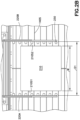
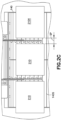
- Each of the telescoping members 300, 301 has any suitable cross section so that at least one of the telescoping members 300, 301 is capable of extending in the space SP ( Fig. 2C ) between adjacent pickfaces 210 arranged on a storage shelf 240.
- a height H of each telescoping member 300, 301 may be substantially larger than a width W of the telescoping member to stiffen the arm 220A, 220B (e.g. to minimize sagging of the arms when extended and to allow greater payload capacity of the arms) which, for example, also facilitates deep storage (e.g. where one or more merchandise case units placed one behind the other).
- Dual-sided picking is also possible, since the arms 220A, 220B are located at the front 200F and rear 200R of the payload bed 200 (it is noted that front and rear are used here for exemplary purposes only and that in other aspects any suitable spatial identifiers may be used to reference the longitudinal sides of the payload bed 200) so as to straddle opposing sides of the pickfaces.
- each arm 220A, 220B which in this aspect is the second telescoping member 301, includes surface 301S such that the fingers 250 extend from the surface 301S towards a centerline CL of the payload bed 200.
- the fingers 250 of each arm oppose one another for extending underneath a pickface.
- the fingers 250 have any suitable length L such that at least one of the telescoping members 300, 301 and the fingers 250 are able to be extended in the space SP ( Fig. 2C ) between pickfaces 210.
- the fingers 250 are fixed relative to the distal most telescoping member (e.g.
- the fingers 250', 250" are, for example, movable relative to the distal most telescoping member 301'.
- fingers 250' are rotatably mounted to the distal most telescoping member 301' such that they are movable between retracted and extended positions. In the retracted position the fingers 250' are, for example, substantially parallel with the surface 310S while in the extended position the fingers 250' are, for example, substantially perpendicular to (or arranged at any other suitable angle relative to) the surface 301S for extending underneath one or more pickfaces 210.
- the fingers 250' are each be rotatable about a respective axis of rotation 363 that extends substantially perpendicular to a direction of extension and retraction 299 ( Fig. 2A ) of the end effector 200E.
- the fingers 250" are, for example, rotatable about an axis of rotation 364 that is substantially parallel with the direction of extension and retraction 299 of the end effector 200E.
- the fingers 250" are movable between retracted and extended positions. In the retracted position the fingers 250" are folded into or adjacent the surface 301S so as to be substantially parallel with the surface 301S.
- the fingers 250" are unfolded so as to be substantially perpendicular to the surface 301S for extending underneath one or more pickfaces 210.
- the fingers are movable relative to the distal most telescoping member in any suitable manner so as to move between a retracted and extended position.
- the opposing arrangement of the fingers 250 is, for example, such that when the arms 220A, 220B are extended into the storage shelf 140 the fingers are located between support surfaces 140S of the storage shelf 140.
- the storage shelf 140 includes spaced apart support surfaces 140S that extend in a direction 297 ( Fig. 2A ) that is substantially perpendicular to (e.g. transverse) the direction of extension and retraction 299 of the end effector 200E.
- a pitch P1 ( Fig. 2A ) between support surfaces 140S is, for example, substantially similar to a pitch P2 ( Fig.
- the spacing between the fingers is any suitable spacing that allows the fingers to pass through the openings between the support surfaces.
- the rover 110 has a drive section 260 that includes any suitable number of drives.
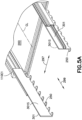
- the drive section 260 includes one or more end effector drives 260A, 260B, 260C configured to move the end effector in extension/retraction along axis 299, move one or more of the arms 220A, 220B so that the arms are moved together and apart in the direction of arrow 297 towards and away from the payload bed centerline CL (see also Fig.5A ), move the arms so that the arms 220A, 220B are moved together as a unit in the direction of arrow 297 relative to the payload bed centerline CL (e.g.
- each transfer arm 220A, 220B is in a plane substantially parallel with a pickface support plane of the payload bed/area to effect a full payload area justification (e.g. a justification of the payload anywhere in within the payload bed and anywhere within a storage shelf area that is accessible by the arms 220A, 220B) of the at least one pickface independent of a size of the at least one pickface.
- a full payload area justification e.g. a justification of the payload anywhere in within the payload bed and anywhere within a storage shelf area that is accessible by the arms 220A, 220B
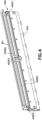
- an end effector extension/retraction drive 260A (e.g. that moves the arms 220A, 220B in the direction of arrow 299) includes any suitable belt transmission 400 for extending and retracting each arm 220A, 220B of the rover 110.
- Each telescoping member 300, 301 (see also Fig. 3A ) includes any suitable belt and pulley arrangement 400P1, 400P2, 400P3, 400B1, 400B2 configured to extend a respective telescoping member 300, 301 in series (e.g.
- the belt and pulley arrangement 400P1, 400P2, 400P3, 400B1, 400B2 are, for example, configured to extend their respective telescoping members 300, 301 substantially simultaneously (e.g.
- telescoping member 300 extends a predetermined distance/reach the telescoping member 301 also extends a corresponding predetermined distance/reach so that telescoping member 300 moves relative to the payload bed 200 and the telescoping member 301 moves relative to both the telescoping member 300 and the payload bed 200).
- retraction of the arms 220A, 220B occurs in a substantially reverse manner to that described above.
- any suitable drive linkage is used to extend and retract the arms 220A, 220B such as, for example, a ball and screw arrangement, chains, hydraulic or pneumatic actuators, electric actuators, magnetic drives, etc.
- an arm gripping drive 260B e.g.
- the arm gripping drive 260B includes one or more drives 260B1, 260B2 for moving one or more of the arms 220A, 220B as described herein.
- the gripping drive 260B includes a single drive motor 260B1 coupled to one or both of the arms 220A, 220B so as to move one arm 220A, 220B relative to the other arm 220A, 220B (e.g.
- the gripping drive 260B includes at least two drives 260B1, 260B2 where each arm 220A, 220B is driven by a respective drive motor 260B1, 260B1 so as to move independently of the other arm 220A, 220B.
- each arm allows not only for the gripping of pickfaces 210 but also for the movement of the pickface 210 in the direction of arrow 297 to effect justification of the pickface 210 in the direction of arrow 297 relative to, for example, a storage space or other pickface holding location.
- the arms 220A, 220B are movable in the direction of arrow 297 in any suitable manner by any suitable number of drive motors.
- the storage shelves 140 are, for example, configured to allow the fingers 250 of the arms 220A, 220B to pass through the shelves 140 so that the fingers 250 are positioned bellow the support surfaces 140S of the shelves 140.
- the storage shelf 140 is a wire shelf such that the support surfaces 140S are formed by the wires of the shelf.
- the wire shelves 140 have any suitable configuration such as a wire mesh configuration where the upper members of the wire shelves form the support surfaces 140S and are oriented and aligned with a direction 297 substantially transverse to a direction 299 in which the pickfaces are transferred to and from the shelves 140.
- the wire shelves 140 are secured to the storage rack structure (e.g. such as horizontal supports 282) and/or the picking aisle deck / rails in any suitable manner.
- the wire shelves 140 wrap around the storage rack structure and/or the picking aisle deck / rails so that the wire shelves 140 are removably fixed to the storage rack structure and/or the picking aisle deck / rails substantially without fasteners or other fixing methods (e.g. adhesives, welding, etc.). In other aspects the wire shelves 140 are removably fixed to the storage rack structure and/or the picking aisle deck / rails with any removable fasteners. In other aspects the shelves 140 may not be removable.
- each storage shelf 140' is substantially similar to that described in United States patent application 12/757,381 filed on April 9, 2010 .
- each storage shelf 140' includes one or more support legs 280L1, 280L2 extending from, for example, horizontal supports 282 of the storage shelf 140'.
- the support legs 280L1, 820L2 have any suitable configuration and may be part of, for example, a substantially U-shaped channel 280 such that the legs are connected to each other through channel portion 280B.
- the channel portion 280B provides an attachment point between the channel 280 and one or more horizontal supports 282.
- each support leg 280L1, 280L2 is configured to individually mount to the horizontal supports 282.
- each support leg 280L1, 280L2 includes a bent portion 280H1, 280H2 having a suitable support surface 140S area configured to support pickfaces stored on the shelf 140'.
- the bent portions 280H1, 280H2 is, for example, configured to substantially prevent deformation of the pickfaces stored on the shelf.
- the leg portions 280H1, 280H2 have a suitable thickness or have any other suitable shape and/or configuration for supporting case units stored on the shelves. As can be seen in Fig.
- the support legs 280L1, 280L2 or channels 280 may form a slatted or corrugated shelf structure where spaces SP2 between, for example, the support legs 280L1, 280L2 allow for fingers 250 of the end effector 200E to reach into the shelving for transferring pickfaces to and from the shelf as will be described below.
- the storage shelves described herein are in one aspect, substantially flat allowing for an increased storage density of the storage and retrieval system 100 while reducing structural costs of the storage and retrieval system 100.
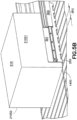
- the storage shelves 140A, 140B, 140C may be stacked one above the other as shown in Figs. 7A-7C so that multiple storage shelves are accessible from a single picking aisle deck 130AD.
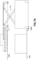
- the end effector lift drive 260C is configured to provide travel of the end effector between multiple storage levels of the storage and retrieval system. For example, referring to Figs.
- the storage shelves 140 allow for a reduction in the number of picking aisles 130A ( Fig. 1 ) which will allow for a reduced transfer deck 130B ( Fig. 1 ) size, and a reduced deck (e.g. both the transfer deck 130B and the picking aisle deck 130AD) by providing multi-level storage per picking aisle deck 130AD.
- the configuration of the shelves 140 also allows for an increase in horizontal and vertical case density while positioning/registering the case units or pickfaces with the arms 220A, 220B may allow for moving the pickfaces closer together (e.g. reducing pickface spacing as described above).
- the spacing between the case units or pickfaces allows space for the arms 220A, 220B to be inserted between adjacent case units or pickfaces to transfer the case unit(s) or pickface to and from the storage shelf 140.
- the rover 110A may be configured to access stacked storage shelves 140A, 140B from a single picking aisle deck 130AD.
- each picking aisle deck 130AD provides access to two levels of storage 140A, 140B but in other aspects each picking aisle may provide access to more than two levels of storage.
- the level of storage accessed by each picking aisle may vary from one picking aisle deck to another picking aisle deck (e.g. one deck may provide access to a first number of storage levels while another deck may provide access to a second number storage levels where the second number is different than the first number).
- the rover 110 may include end effector lift drive 260C ( Fig.
- the end effector lift drive 260C is any suitable drive section configured to raise and lower the arms 220A, 220B such as, for example, a linear actuator, a screw drive, scissor lift 777 ( Fig. 7A ), a magnetic drive, etc.
- the rover 110 receives a command from, for example, any suitable controller such as control server 120 ( Fig. 1 ) to transfer a pickface.
- the rover travels along the transfer deck 130B to a predetermined picking aisle 130A.
- the rover 110 enters the picking aisle 130A and stops at a predetermined storage location. ( Fig. 5D , Block 500) .
- the rover 110 includes end effector 200E having arms 220A, 220B that are configured to straddle and interface with opposing sides 210S1, 210S2 of the pickface 210 and to transfer the pickface 210 to and from the payload bed 200.
- the arms 220A, 220B are retracted within the payload bed 200 and the rover 110 is not carrying a pickface, the arms 220A, 220B are separated by a distance D1 that is substantially larger than a width W of the widest pickface the rover is capable of carrying and/or that is stored in the storage and retrieval system 100.
- the rover controller 110C operates the end effector drive section 260 to longitudinally move one or more of the arms 220A, 220B to align the arms 220A, 220B with the storage location according to, for example, the width W of the pickface 210 ( Fig. 2B ).
- the rover 110 includes any suitable sensors (as will be described below) configured to detect the sides 210S1, 210S2 of the pickface (s) located on the storage shelves 140 as the rover moves along the picking aisle(s) 130A ( Fig. 1 ).
- the pickfaces 210 are positioned on the storage shelves 140 relative to predetermined features of the storage shelves such that the sensors may detect the predetermined features of the storage shelves to determine the locations of the pickface (and the pickface sides).
- the case sensors are substantially similar to those described in United States patent applications 13/327,035 filed on December 15, 2011 ( PG Pub. 2012/0189410 ) and 13/608,877 filed on September 10, 2012 entitled "Storage and Retrieval System Case Unit Detection,"
- the rover 110 moves one or more of the arms 220A, 220B to adjust the distance D1 between the arms 220A, 220B so that when extended the arms 220A, 220B are positioned within the spaces SP ( Fig.
- the rover 110 includes justification in the direction of arrow 297, the telescoping arms of the rover are moved as a unit in the direction of arrow 297 to further align the arms with the pickface upon picking the pickface from a holding location (or to align the pickface with a holding location upon placement of the pickface at a holding location), e.g. fine positioning of the telescoping arms relative to a pickface holding location ( Fig. 5D , Block 501A).
- the rover 110 controller 110C ( Fig.
- the arms 220A, 220B are moved in direction 298 independent of a support surface of the payload bed 200 while in other aspects the support surface of the payload bed also are configured move (either by the drive 260C or with a payload bed lift drive) in direction 298 so that the payload bed support surface is adjacent the support surface 140S from which the pickface is to be transferred from/to in a manner substantially similar to that described in United States provisional patent application 61/790, 801 .
- any suitable sensor 257 provides feedback to the controller 110C for determining how deep the arms 220A, 220B are extended into the storage location and to determine the leading and trailing edge boundaries (with respect to the direction of extension of the arms 220A, 220B) of the pickface (as will be described below with respect to the justification of the pickface).
- the arms 220A, 220B are lowered with drive 260C so that the fingers are positioned a predetermined distance D2 below the shelf support surface 140S ( Fig. 5D , Block 503).
- One or more of the arms 220A, 220B are moved in the direction of arrow 297 with drive 260B towards the sides 210S1, 210S2 of the pickface 210 so that the surface 301S of, for example, telescoping member 301 lightly grips the pickface (e.g. where lightly grip means touching the pickface for alignment of the pickface such that the touching does not provide enough grip to hold the pickface for lifting the pickface off the storage shelf) and the fingers 250 are located beneath the pickface 210 ( Fig. 5D , Block 504).
- the surfaces 301S may provide sufficient grip for lifting the pickface.
- the pickface 210 may be lifted in the direction of arrow 298 any suitable distance D3 from the storage shelf 140 by lifting the arms 220A, 220B using drive 260C so that the fingers 250 are raised to contact bottom 210B ( Fig. 2A ) of the pickface (e.g. the pickface may slide along the surface 301S to allow contact between the fingers 250 and the bottom 210B of the pickface) ( Fig. 5D , Block 505) for supporting the weight of the pickface.
- the arms 220A, 220B may be retracted in the direction of arrow 299 so that the pickface is located above the payload bed 200 ( Fig.
- the pickface 210 When located within the payload bed the pickface 210 is, in one aspect, supported by the fingers and/or by any suitable support surface of the payload bed 200. As may be realized, the surfaces 301S are, in one aspect, employed to justify the pickface ( Fig. 5D , Block 508) within the payload bed (e.g. locate the pickface at a predetermined position relative to one or more reference datums of the payload bed) in any suitable manner such as that described below where one or more of the arms 220A, 220B are moved in the direction of arrow 297 for justification of the pickface.
- the pickface is, in one aspect, held or clamped by the surfaces 301S of the arms 220A, 220B or any other suitable alignment / gripping surfaces of the rover.
- the rover 110 may be positioned at a predetermined location relative to the pickface holding location. In one aspect, where the pickface 210 is justified, the pickface 210 is moved by the arms 220A, 220B in the direction of arrow 297 within the payload bed 200 to align the pickface 210 with the pickface holding location. In other aspects the positioning of the rover 110 effects alignment of the pickface 210 with the pickface holding location.
- the arms 220A, 220B raise the pickface to a level substantially equal to or above the support surface 140S of the pickface holding location and the arms transfer the pickface 210 onto the support surface 140S of the pickface holding location in a manner substantially opposite to that described above for transferring the pickface onto the payload bed 200.
- transfer of payload to and from the rover 110 is described with respect to pickface 210 it should be understood that the above-description also applies to transfer of individual case units to and from the rover 110.
- the rover may transfer a case unit and/or a pickface formed of case units to any suitable pickface holding location such as the storage shelves 140, 140', 140A, 140B, a shelf of a lift 150A, 150B or any other suitable location.
- the rover 110 is positioned to transfer one or more first pickfaces 210 from a shelf to the rover 110 in a manner substantially similar to that described above ( Fig. 17 , Block 8000).
- a spacing D1 between the arms 220A, 220B is adjusted in the direction of arrow 297 to align the arms 220A, 220B with the one or more first pickfaces 210 (so as to fit in the space SP between adjacent case units/pickfaces) as illustrated in Fig. 2C ( Fig. 17 , Block 8001).
- the rover 110 includes justification in the direction of arrow 297, the telescoping arms of the rover are moved as a unit in the direction of arrow 297 to further align the telescoping arms 220A, 220B with the one or more first pickfaces 210, e.g. fine positioning of the telescoping arms relative to a pickface holding location ( Fig. 17 , Block 8001A).
- the telescopic arms 220A, 220B are extended and retracted in the direction of arrows 299A, 299B to transfer the one or more first pickfaces 210 to the payload bay ( Fig. 17 , Block 8003) in the manner described above with respect to Blocks 502-508 of Fig.
- the rover 110 traverses the picking structure and is positioned relative to another pickface holding location ( Fig. 17 , Block 8000) for the transfer of one or more second pickfaces 210X ( Fig. 2C ) to the payload bay 200.
- the one or more first pickfaces 210 within the payload bay are unclamped and the spacing between the telescoping arms 220A, 220B are adjusted ( Fig. 17 , Block 8001) and/or justified ( Fig. 17 , Block 8001A) so as to align the telescoping arms 220A, 220B with the one or more second pickfaces 210X in the other pickface holding location.
- the one or more first pickfaces 210 already held on the payload bed 200 are moved with the telescoping arms 220A, 220B in the direction of arrow 297 as the telescoping arms are justified.
- the telescopic arms 220A, 220B are extended and retracted in the direction of arrows 299A, 299B to transfer the one or more second pickfaces 210X to the payload bay ( Fig. 17 , Block 8003) in the manner described above with respect to Blocks 502-508 of Fig. 5D .
- the telescoping arms 220A, 220B may be spaced from the sides of the one or more first pickfaces 210 so that the fingers 250 do not contact the one or more first pickfaces in the payload bay 200 (and/or referring Figs. 3B and 3C one or more of the fingers 250', 250" are positioned, e.g. retracted, so as to not contact the pickface 210 in the payload bay 200).
- the fingers 250 furthest from the free ends FE ( Fig.
- the arms 220A, 220B are longer than the fingers 250 adjacent the free ends FE so that the one or more first pickfaces 210 are held by the arms 220A, 220B during picking of the one or more second pickfaces 210X while still allowing the arms 220A, 220B to be spaced apart so as to straddle the one or more second pickfaces 210X without contact as the arms 220A, 220B are extended into the holding location.
- the one or more first and second pickfaces 210, 210X are transferred as a unit by the rover 110 and placed at a pickface holding location as a unit (or at more than one pickface holding location separately) in a manner substantially opposite to that described above with respect to transfer of the pickfaces 210, 210X into the payload bed 200.
- the rover 110 include justification features such as those described in United States provisional patent application number 14/215,310 filed on March 17, 2014 entitled "Automated Storage and Retrieval System".
- the rover 110 includes active side justification (where, as noted above, one arm 220A, 220B is fixed and the other arm 220A, 220B is movable in direction 297 or where both arms 220A, 220B are movable in direction 297).
- Suitable sensors 257 for physical confirmation of case boundaries may also be located adjacent to or within the payload bed 200 and/or on one or more of the arms 220A, 220B.
- the sensors 257 are beam line or curtain sensors disposed on the arms 220A, 220B of the rover.
- the sensors 257 allow the rover to, on placing pickfaces, confirm empty and adequate space exists on any suitable pickface holding location, such as for example a storage shelf 140, 140', 140A, 140B for a pickface and to confirm that the pickface is placed with the correct setback (e.g. the distance the pickface is located from a picking aisle edge of the pickface holding location or any other suitable reference datum).
- the sensors 257 allow for case targeting and confirmation of the depth to which the arms 220A, 220B are extended into the storage location.
- the arms 220A, 220B also, in one aspect, provide guidance for pickfaces being placed in deep storage locations (e.g. at storage locations that are distant from an edge of, e.g., the storage shelf 140).
- the payload bed 200 of the rover 110 is, in one aspect, configured to allow multi-degree of freedom sliding movement of the pickface 210 (and the case units forming the pickface) along the surface of the payload bed 200.
- the payload bed is a substantially flat surface constructed of any suitable material having a low coefficient of friction, while in other aspects the payload bed include a plurality of ball bearings on which the pickface rides, while in still other aspects the payload bed 200 has any suitable construction, such as that describe above, that allows for the multi-degree of freedom sliding movement of the pickface 210 (and the case units forming the pickface) along the surface of the payload bed 200.
- the pickface is justified while being held above the payload bed surface by the fingers 250.
- the rover 110 includes any suitable sensors for detecting the position of the pickface(s) 210 located on the storage shelves 140.
- the rover includes one or more beam sensors 600, 601 and/or proximity sensors 602, 603 that may be positioned on the frame 110F of the rover 110 below the payload bed 200 to sense predetermined features or targets 611, 612, 613 (e.g. slots, protrusions, etc.) disposed on or in horizontal supports 282 of the storage shelf 140.
- the sensors 600, 601, 602, 603 are positioned, for example, to sense the targets 611, 612, 613 on the horizontal supports 282 so that as each target 611, 612, 613 is sensed by a respective sensor 600, 601, 602, 603 that sensor produces an on/off signal for determining a position of the rover in a manner substantially similar to that described in United States provisional patent application number 61/790,801 .
- the rover has sensors 700, 701 on both lateral sides of the rover 110S1, 110S2 so that the sensors 600, 601, 602, 603 may detect the targets 611, 612, 613 regardless of the travel orientation of the rover where the targets 611, 612, 613 are located on but one horizontal support 282 in the picking aisle 130A.
- the sensors are to detect the pickfaces 210 located on the storage shelf 140 rather than the targets the sensors are located on the rover at any suitable height for detecting the pickfaces 210.
- the beam sensors 600, 601 and one or more proximity sensors 602, 603 are used in conjunction with each other for determining a position of the rover within the storage structure.
- the proximity sensors 602, 603 is used to determine a location of the rover within the picking aisle 130A while the beam sensors 600, 601 is used to determine a location of the rover in an area between the targets 611, 612, 613 for aligning the arms 220A, 220B of the rover 110 with the spaces SP between the pickfaces 210 for transferring pickfaces 210 between the rover 110 and the storage shelf 140, while in other aspects the beam sensors 600, 601 and proximity sensors 602, 603 are used in any suitable manner for determining a location of the rover within the storage structure and for transferring pickfaces between the rover 110 and the storage shelves 140.
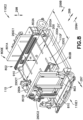
- a rover 110 is illustrated in accordance with an aspect of the disclosed embodiment.
- the rover 110 is substantially similar to that described above except where noted.
- the rover 110 includes a frame 110F having a first end 110E1 and a second end 110E2 longitudinally spaced from the first end 110E1.
- the frame 110F forms a payload area 200A in which a Cartesian telescopic manipulator 800E is mounted.
- the manipulator 800E as will be described below, is configured to handle pickfaces 210 ( Fig. 2A ) of variable length and width by, for example pushing or pulling the pickfaces 210 between any suitable storage shelf and a payload bay of the rover 110.
- the storage shelf may be substantially similar to storage shelf 140 ( Fig. 2A ) described above while in other aspects the storage shelf may include a substantially flat pickface support surface or a slatted pickface support surface rather than a wire rack pickface support surface.
- the manipulator 800E includes a drive section having at least a three degree of freedom drive (as will be described below), one or more telescoping arms 802A, 802B (e.g. generally end effector 802), a payload bay 200 and at least one mast assembly or member 801A, 801B.
- the payload bay 200 is suspended between two mast assemblies or members 801A, 801B which are mounted to the payload area 200A of the frame 110F while in other aspects the payload bay 200 may be cantilevered from a single mast member (such as one of mast members 801A, 801B).
- the mast members 801A, 801B include guides for effecting movement of the payload bay 200 in the direction of arrow 298 (e.g. vertically relative to a surface on which the rover travels).
- the end effector 802 is mounted at least partly within the payload bay 200 so as to extend and retract in the direction of arrow 299 so as to reach/extend outside of the payload bay 200 for transferring pickfaces 210 between the payload bay 200 and a shelf 140.
- the end effector 802 includes two telescoping arms 802A, 802B disposed substantially at opposite sides (e.g. in the direction of arrow 297) of the payload bay 200.
- the telescoping arms 802A, 802B are mounted at least partly within the payload bay 200 so as to be movable towards and away from each other within the payload bay in the direction of arrow 297.
- the payload pay 200 is configured to support a pickface 210 within the payload bed 200 in any suitable manner such as on a substantially flat surface or plate 200S.
- each mast member 801 includes a frame 801F, a carriage 803 and a drive 810 (e.g. a vertical drive).
- the frame 801F forms two opposing channels 801C disposed on opposite vertical sides of the frame 801F.
- the carriage 803 extends between and is mounted within the channels 801C so as to move vertically in the direction of arrow 298.
- the carriage 803 includes guide wheel members or assemblies 803G mounted at opposite ends 803E1, 803E2 of the carriage 803.
- Each guide wheel member includes one or more guide wheels 803R1A, 803R1B, 803R2 that engage one or more sides of a respective channel 801C.
- each guide member 803G includes guide wheels 803R1A, 803R1B, 803R2 that stabilize the carriage in one or more of directions 297, 299.
- each guide member 803G includes one or more guide wheels 803R1A, 803R1B that engage opposite sides 801CS1, 803CS2 of a common channel 801C (e.g.
- wheel 803R1A engages side 803CS2 while wheel 803R1B engages side 803CS1 or vice versa) so as to stabilize movement of the carriage 803 in the direction of arrow 297 and one or more guide wheels 803R2 that engages the other side of the channel 801C (spanning between the opposite sides) for stabilizing movement of the carriage 803 in the direction of arrow 299.
- the guide wheel members 803G are mirror images of one another so that the uppermost (e.g.
- Torsional movement TM2 of the carriage 803 about an axis extending in the direction of arrow 297 is substantially eliminated with a wire rope reeving that includes wires 803W1, 803W2 and pulleys 803P1, 803P2, where the pulleys 803Pa, 803P2 are mounted to the carriage 803 and ends 803WE of wires 803W1, 803W2 are anchored to, for example a respective mast member 801.
- the wire rope reeving is arranged so that the wire ropes 802W1, 803W2 pass through the pulleys so as to cross and exit the reeving at an opposite side and/or end of the frame 803F.
- wire rope 803W1 enters the frame at end 803E2, engages pulley 803P1, travels along a length of the frame, engages pulley 803P2 and then exits the frame from the opposite side at opposite end 803E1.
- wire rope 803W2 enters the frame at end 803E1, engages pulley 803P2, travels along a length of the frame while crossing wire rope 803W1, engages pulley 803P1 and then exits the frame from the opposite side at opposite end 803E2.
- This crossed reeving arrangement constrains the carriage in a predetermined orientation (e.g. horizontally) for travel along the mast 801.
- the carriage 803 is driven in the direction of arrow 298 in any suitable manner such as by drive 810 (e.g. vertical drive) which includes a belt and pulley drive system but in other aspects a lead screw drive or other linear actuator drives the carriage in the direction of arrow 298.
- the drive 810 includes a frame 810F that is mounted to the mast 801.
- a drive motor 260C is mounted to the frame 810F so as to drive belt 810B with a pulley 810P2 mounted to an output shaft of the drive motor 260C.
- the belt 810B is wound around and guided by one or more pulleys 801P1, 801P3, 801P2, which are mounted to the frame 810F.
- the belt 810B is fixed to the carriage via mount 803B of the carriage 803 so that as the belt 810B moves the carriage 803 moves with the belt 810B in the direction of arrow 298.
- the drives 810 are driven by a Master-Slave control system, such as controller 110C ( Fig. 1 ) so the payload bay 200 suspended between the mast members 801A, 801B is kept level.
- controller 110C Fig. 1
- the vertical positioning of the payload bay 200 within limits of travel defined by, for example, at least the mast members 801 is infinite.
- a height of the channels 801C and/or width of the frame 801F e.g.
- each mast member 801 includes channels 801A so that the carriage 803 and the payload bay 200 can be coupled to each other so that the carriage(s) 803 support or otherwise carry the payload bay 200 (e.g. the payload bay depends from the carriage(s) 803).
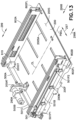
- the payload bay 200 includes a frame 200F and a pickface support surface 200S (not shown in Fig. 11 ) mounted to the frame 200F.
- the frame 200F defines opposing channels 200C1, 200C2 in which two effector carriages 200G1, 200G2 are mounted so as to travel in the direction of arrow 297.
- each effector carriage (generally effector carriage 200G) includes a frame 200GF having guide wheel carriages 200RC disposed at opposite ends 200GE1, 200GE2.
- Each guide wheel carriage 200RC includes one or more guide wheels 200GP1A-200GP1D configured to engage one or more walls of the channel 200C to stabilize movement of the effector carriage 200G from movement in the directions of arrows 298, 299.
- guide wheels 200GP1A-200GP1D configured to engage one or more walls of the channel 200C to stabilize movement of the effector carriage 200G from movement in the directions of arrows 298, 299.
- each guide wheel carriage 200RC includes one or more guide wheels that engages the opposing sides 200CS1, 200CS2 of a respective channel 200C so as to stabilize movement of the effector carriage 200G in the direction of arrow 298 (as well as substantially eliminate torsional movement TM3 of the effector carriage 200G about an axis substantially parallel with the direction 299) and one or more guide wheels that engage the other wall 200CS3 of the respective channel 200C so as to stabilize movement of the effector carriage 200G in the direction of arrow 299.
- Torsional movement TM4 of the effector carriage 200G about an axis substantially parallel with the direction of arrow 298 is substantially eliminated by a wire rope reeving (which is similar to that described above) in a manner substantially similar to that described above with respect to carriage 803 where the wire rope reeving includes wires 200W1, 200W2 and pulleys 200P1-200P4 mounted to the frame 200GF where the ends 200WE of the wires 200W1, 200W2 are secured or otherwise fixed to, for example, the frame 200F of the payload bed or any other suitable portion of the rover 110.
- Each effector carriage also includes a drive belt coupling member 200GBA for fixing the respective effector carriage 200G to the drive belt 260DB.
- a motor 260D mounted to the frame 200F, drives the drive belt 260DB (which is mounted to the frame 200F with pulleys 260DP1, 260DP2) to move the effector carriages 200G1, 200G2 towards and away from each other where one effector carriage 200G1 is attached to a top 260DBT of the drive belt 260DB (which loops around the pulleys 260DP1, 260DP2) and other effector carriage 200G2 is attached to a bottom 260DBB of the drive belt 260DP loop.
- the effector carriage 200G1, 200G2 positions are infinite between their limits of travel.
- the length and width of the payload bay 200 can be sized to support a pickface having any suitable length and width as the effector carriages 200G1, 200G2 are adjusted to accommodate various size pickfaces.
- one or more arm mounts 200M are affixed to each effector carriage 200G1, 200G2 so that the telescoping arms 802A, 802B are mounted to a respective one of the carriages 200G1, 200G2.
- the arm mounts 200M extend through the pickface support surface 200S of the payload bay 200 so as to travel within slots or apertures 200SA formed in the pickface support surface 200S.
- each effector carriage 200G1, 200G1 is movable independent of the other effector carriage in a manner similar to that described above so that a pickface(s) is justified in the direction of arrow 297 relative to the frame 110F and/or a pickface holding location.
- one of the effector carriages 200G1, 200G2 is coupled to the drive belt 260DB for movement in the direction of arrow 297 by motor 260D.
- the other effector carriage 200G1, 200G2 is coupled to a second drive belt 260DB2 (in a manner substantially similar to that described above) for movement in the direction of arrow 297 by a second motor 260D2 (substantially similar to motor 260D).
- each effector carriage, and hence each telescoping arm 802A, 802B, is independently movable and movable together so that a pickface can be justified in the direction of arrow 297 by moving one or more of the telescoping arms 802A, 802B.
- each of the telescoping arms 802A, 802B includes three links 802FL, 802CL, 802IL but in other aspects each telescoping arm 802A, 802B includes any suitable number of links, such as more or less than two links.
- each telescoping arm includes a fixed link 802FL mounted to the arm mounts 200M, a center link 802CL, and inner link 802IL.
- the center link 802CL is mounted to the fixed link 802FL through any suitable linear slide 802CR or other linearly movable joint so as to be movable relative to the fixed link 802FL in the direction of arrow 299.
- the inner link 802IL is mounted to the center link 802CL through any suitable linear slide 802IR or other linearly movable joint so as to be movable relative to the center link 802CL in the direction of arrow 299.
- a drive belt 501B is mounted on the fixed link 802FL through pulleys 501P1, 501P2 where pulley 501P1 is driven a driven pulley having a drive coupling 501.
- a drive motor 260A is mounted to the frame 200F and is operatively coupled to one or more drive shafts 500A, 500B (two drive shafts are shown in the drawings while in other aspects more or less than two drive shafts are employed) through any suitable transmission 260AT such as, for example, a belt and pulley transmission, a gear drive transmission, a chain drive transmission or any other drive coupling.
- the one or more drive shafts 500A, 500B connect the motor to the drive coupling 501 so as to drive the pulley 501P1 and hence, the belt 501B.
- the center link 8012CL is coupled to the belt 501B with coupling 501C so that as the belt 501B moves the center link 802CL moves with the belt 501B in the direction of arrow 299.
- Another drive belt 501B2 is mounted on the center link 802CL with pulleys in a manner similar to that described above with respect to belt 501B.
- the belt 501B2 is fixed to both the fixed link 802FL and the inner link 802IL so that as the center link 802CL is driven in the direction of arrow 299, the slaved nature of the belt 501B2 causes relative movement between the inner link 802IL and the center link 802CL so that the inner link 802IL also moves in the direction of arrow 299 and the links 802FL, 802CL, 802IL extend in a telescoping manner.
- a pickface engagement or pusher member 900T is mounted to the inner link 802IL so as to be movable in the direction of arrow 299.
- Another pickface engagement or finger member 900F is also mounted on inner link 802IL so as to be rotatable about an axis FAX, which is substantially parallel with the direction of arrow 299, so as to be rotated between a deployed position (see Fig. 14B ) and a retracted position (see Fig. 14A ).
- the pusher member 900T is driven by a linear drive or actuator 900TM so as to reciprocate in the direction of arrow 299 within aperture 900TA of the inner link 802IL.
- the pusher member 900T includes a pickface engagement surface 900TS that extends in the direction of arrow 297 towards a centerline PBCL of the payload bay 200 so as to, when moved in the direction of arrow 299A, push a pickface onto a predetermined shelf 140.
- the pusher member 900T effects a justification of a pickface(s), when being placed into a pickface holding location, in the direction of arrow 299 independent of, for example, one or more of pickface size, the storage rack structure (e.g. the pickface holding location) and extension/retraction of the telescoping arms 802A, 802B.
- the movement of the pusher member in the direction of arrow 299 effects an independently variable justification of a pickface along a direction of extension and retraction across the storage rack (pickface holding location) and independent of the extension/retraction of the telescoping arms 802A, 802B.
- the movement of one or more of the pusher member 900T in the direction of arrow 299 along with the movement of the arms 802A, 802B in the direction of one o more of arrows 299, 297 is in a plane substantially parallel with a pickface support plane of the payload bed/area to effect the full payload area justification (e.g., as noted above, a justification of the payload anywhere in within the payload bed and anywhere within a storage shelf area that is accessible by the arms 220A, 220B) of the at least one pickface independent of a size of the at least one pickface.
- the finger member 900F is rotatably mounted on the inner link 802IL through any suitable drive such as rotary motor 900FM. Also referring to Fig. 13A , the finger member 900F is disposed in the retracted position to allow the pickface 210 to travel past the free end FE when being pushed onto a shelf 140 or during extension of the end effector 802 into a pickface storage location on a shelf 140, e.g. so that each telescoping arm is extended between adjacent pickfaces so as to straddle a pickface being picked without interfering with the pickfaces located on the shelf 140.
- the finger member 900F includes a pickface engagement surface 900FS that engages a predetermined pickface to pull the pickface off the shelf 140 as the telescoping arms 802A, 802B move out of the shelves and transport the pickface into the payload bay 200.
- the finger member 900F is located at the free end FE of the inner link 802IL and rotates about axis FAX. In operation, when the telescoping arms 802A, 802B (e.g.
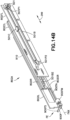
- the end effector 802 are extended into a shelf 140 for picking a pickface 210 the finger member 900F is positioned past the end 210E of the pickface 210 and then rotated to the deployed position so that the pickface engagement surface 900FS is disposed behind the pickface 210.
- the pickface engagement surfaces 900FS of the fingers 900F engage the pickface 210 and pull the pickface 210 into the payload bay 200.
- the pusher member 900T is movable in the direction of arrow 299 towards or away from the finger member 900F.
- This reciprocating movement of the pusher member 900T relative to the finger member 900F effects the gripping (e.g. capture) and releasing of pickfaces (e.g. pickfaces having varying depths/sizes DP) between the finger members 900F and the pusher members 900T.
- Relative movement between the pusher members 900T and the finger members 900F also effects a justification of a pickface at the free end FE of the telescoping arms 802A, 802B (e.g. the end effector 802) so that the pickface is be pushed onto a shelf at an infinite number of predetermined positions dependent on, for example, an extension length of the end effector 802.
- one or more of the telescoping arms 802A, 802B includes a wireless control module 910 for controlling the pusher member motor 900TM and finger motor 900FM of a respective one of the arms or both arms 802A, 802B.
- each telescoping arm 802A, 802B includes a respective wireless control module 910 for controlling the respective motors 900TM, 900FM while in other aspects a common wireless control module 910 can control the motors 900TM, 900FM on both telescoping arms 802A, 802B.
- the wireless control module(s) 910 is mounted to the inner link 802IL of a respective telescoping arm 802A, 802B while in other aspects the wireless control module 910 is mounted at any suitable location of the respective telescoping arm 802A, 802B.
- the wireless control module 910 is configured for wireless communication with, for example, the rover controller 110C ( Fig. 1 ) in any suitable manner such as, for example, Bluetooth, infrared, radio frequency or any other form of wireless communication.
- the wireless control module 910 includes a battery 910B to provide power to the motors 900TM, 900FM and contacts 910C for charging the battery 910B.
- the contacts 910C engage contacts 200CT of the payload bay 200 so that the batteries are recharged.
- the contacts are illustrated as mechanical contacts but in other aspects the recharging of the battery 910B may be effective through contactless charging such as by induction.
- wireless control of the pusher member motor 900TM and the finger motor 900FM substantially eliminates flexing wires between, for example, the payload bay 200 and each link of the telescoping arms 802A, 802B which can occupy a lot of space and can be a reliability problem.
- a single motor such as motor 260A drives both telescopic arms as best illustrated in Fig 13 .
- the motor 260A is mounted to the frame 200F of the payload bay 200 at, for example, in the middle rear of the payload bay 200 but in other aspects the motor 260A may be mounted at any suitable location relative to the payload bay 200.
- the motor 260A is coupled to any suitable transmission such as belt and pulley transmission 260AT, a chain drive transmission, a gear drive transmission or any other transmission.
- the transmission 260AT couples an output shaft of the motor 260A with, for example, drive shafts 500A, 500B which are oriented substantially perpendicular to the telescoping arm 802A, 802B so as to extend in either direction from, for example, the transmission 260AT. While two drive shafts 500A, 500B are illustrated, in other aspects a single drive is used.
- the drive shafts 500A, 500B may be any suitable shafts that include any suitable drive engagement or coupling such as, for example, spline couplings, hex couplings, flange couplings, beam couplings, rigid couplings or any other coupling for coupling the shafts 500A, 500B to the transmission 260AT and pulleys 501P1 as will be described below.
- pulley 501P1 includes a drive coupling 501 that mates with the drive coupling of a respective one of the drive shafts 500A, 500B.
- the coupling between the shafts 500A, 500B and the pulley 501P1 is a floating coupling so that the drive shafts 500A, 500B are supported by the drive coupling 501 of the pulleys 501PS disposed on in the fixed arms links 802FL in order to avoid binding from, for example, misalignment.
- each pulley 501P1 As each pulley 501P1 is driven by a respective drive shaft 500A, 500B, each pulley 501P1 in turn drives the belt 501B on the fixed arm link 802FL of each arm 802A, 802B so as to power or otherwise drive the telescopic motion of the arms 802A, 802B.
- the drive shafts 500A, 500B are configured so the drive coupling extends along the length of the drive shaft 500A, 500B so that the pulley 501P1 is able to slide along the length of the respective drive shaft 500A, 500B while maintaining a driving engagement with the drive shaft 500A, 500B.
- each pulley 501P1 slides along the drive shaft 500A, 500B allowing the arms to be extended and retracted in an infinite number of positions within the limits of travel along the direction of arrow 297.
- the structure of the manipulator 800E (as described herein) can be extremely light weight.
- the masts 801A, 802B, payload bay 200 and the components thereon e.g. for driving the telescoping arms 802A, 802B in the directions of arrows 298, 297 employ standard aluminum channel and aluminum skins held together with high strength adhesive.
- This type of construction allows the individual frames 200F, 200GF, 801F, 803F to be configured for large or small payloads depending on the variation of pickfaces to be handled.
- the telescopic arms 802A, 802B are also easily configured for varied depths of travel.
- the rover 110 is positioned to transfer a pickface from a shelf to the rover 110 in a manner substantially similar to that described above ( Fig. 15 , Block 5000).
- a spacing between D1' between the arms 802A, 802B is adjusted in the direction of arrow 297 to align the arms 802A, 802B with a pickface (so as to fit in the space SP between adjacent pickfaces) as illustrated in Fig. 13A ( Fig. 15 , Block 5001).
- the rover 110 includes justification in the direction of arrow 297, the telescoping arms of the rover are moved as a unit in the direction of arrow 297 to further align the pickface with a holding location (or to align the arms with the pickface), e.g. fine positioning of the telescoping arms relative to a pickface holding location ( Fig. 15 , Block 5001A).
- the payload bay 200 is moved in the direction of arrow 298 to substantially align the pickface support surface 200S of the payload bay 200 with a support surface (or plane) 140SPL of the shelf 140 as illustrated in Fig. 13B ( Fig. 15 , Block 5002).
- the telescopic arms 802A, 802B are extended in the direction of arrow 299A (e.g. with the fingers 900F in the retracted position) so that the fingers 900F are placed behind (relative to the rover 110) or past an end 210E of the pickface 210 as illustrated in Fig. 13A ) ( Fig. 15 , Block 5003).
- the fingers 900F are rotated to a deployed position (as illustrated in Figs. 13A and 14B ) ( Fig. 15 , Block 5004) and the telescoping arms 802A, 802B are retracted in the direction of arrow 299B so that the fingers 900F engage the pickface 210 and pull (e.g.
- the pickface is slide) the pickface from the shelf 140 to the pickface support surface 200S of the payload bay 200 ( Fig. 15 , Block 5005).
- suitable clearance is provided between the inner arm links 802IL and the pickface 210 to allow the pickface to move between the inner arm links 802IL, however it should be understood that in one aspect the clearance is minimal so that the inner arm links 802IL guide movement of and justify (in the direction of arrow 297) the pickface within the payload bay. In other aspects the pickface is justified in the direction of arrow 297 in the payload bay 200, e.g. along a centerline CL ( Fig.
- the pusher members 900T are actuated in the direction of arrow 299A so as to move the pickface 210 against the fingers 900F so as to capture or clamp the pickface 210 between the pusher member(s) 900T and the finger(s) 900F ( Fig. 15 , Block 5007) to allow, for example, transport of the pickface.
- the clamping of the pickface 210 between the pusher member(s) 900T and the fingers 900F also justifies the pickface 210 in the direction of arrow 299 so that the pickface can be placed at any suitable depth on a predetermined shelf 140 or other holding location ( Fig. 15 , Block 5008).
- the fingers 900F are disengaged from the pickface and the movement of the pusher members(s) 900T alone, in the direction of arrow 299, effects the justification of the pickface 210 in the direction of arrow 299 so that the pickface can be placed at any suitable depth on a predetermined shelf 140 or other holding location.
- the picking process described above may be repeated so that multiple pickfaces are arranged along the direction of arrow 299 within the payload bay 200.
- the rover 110 is positioned to transfer a pickface from a shelf to the rover 110 in a manner substantially similar to that described above ( Fig. 16 , Block 6001).
- the rover 110 includes justification in the direction of arrow 297, the telescoping arms of the rover are moved as a unit in the direction of arrow 297 to further align the pickface with a holding location (or to align the arms with the pickface), e.g. fine positioning of the telescoping arms relative to a pickface holding location ( Fig. 16 , Block 6001A).
- the payload bay 200 is moved in the direction of arrow 298 to substantially align the pickface support surface 200S of the payload bay 200 with a support surface (or plane) 140SPL of the shelf 140 as illustrated in Fig. 13B ( Fig. 16 , Block 6002).
- the fingers 900F are rotated to the retracted position shown in, e.g., Fig. 14A (as may be realized the gripping of the pickface between the pusher member(s) 900T and the finger(s) 900F may be sufficiently released to allow movement of the finger(s) 900F) ( Fig. 16 , Block 6003).
- the telescoping arms 802A, 802B are extended in the direction of arrow 299A so that the pusher members 900T push or slide the pickface 210 from the pickface support surface 200S of the payload bay to a support surface 140SPL of the shelf 140 or other pickface holding location ( Fig. 16 , Block 6004).
- the pusher members 900T are moved in the direction of arrow 299A during and/or after the extension of the telescoping arms 802A, 802B to further position the pickface in the direction of arrow 299A.
- Fig. 8 an exemplary pickface building operation of the rover 110 will be described.
- the rover 110 is positioned to transfer one or more first pickfaces 210 ( Fig.
- a spacing D1' between the arms 802A, 802B is adjusted in the direction of arrow 297 to align the arms 802A, 802B with the one or more first pickfaces 210 (so as to fit in the space SP between adjacent case units/pickfaces) as illustrated in Fig. 13A ( Fig. 18 , Block 7001).
- the rover 110 includes justification in the direction of arrow 297, the telescoping arms of the rover are moved as a unit in the direction of arrow 297 to further align the telescoping arms 802A, 802B with the one or more first pickfaces 210, e.g. fine positioning of the telescoping arms relative to a pickface holding location ( Fig. 18 , Block 7001A).
- the payload bay 200 is moved in the direction of arrow 298 to substantially align the pickface support surface 200S of the payload bay 200 with a support surface (or plane) 140SPL of the shelf 140 as illustrated in Fig. 13B ( Fig. 18 , Block 7002).
- the telescopic arms 802A, 802B are extended and retracted in the direction of arrows 299A, 299B to transfer the one or more first pickfaces 210 to the payload bay ( Fig. 18 , Block 7003) in the manner described above with respect to Blocks 5003-5007 of Fig. 15 .
- the rover 110 traverses the picking structure and is positioned relative to another pickface holding location ( Fig. 18 , Block 7000) for the transfer of one or more second pickfaces 210X ( Fig. 2C ) to the payload bay 200.
- the one or more first pickfaces 210 within the payload bay are unclamped and the spacing between the telescoping arms 802A, 802B are adjusted ( Fig. 18 , Block 7001) and/or justified ( Fig. 18 , Block 7001A) so as to align the telescoping arms 801A, 802B with the one or more second pickfaces 210X in the other pickface holding location.
- the one or more first pickfaces 210 already held on the payload bed 200 are moved with the telescoping arms in the direction of arrow 297 as the telescoping arms are justified.
- the payload bay 200 is moved in the direction of arrow 298 to substantially align the pickface support surface 200S of the payload bay 200 with a support surface (or plane) 140SPL of the shelf 140 as illustrated in Fig. 13B ( Fig. 18 , Block 7002).
- the telescopic arms 802A, 802B are extended and retracted in the direction of arrows 299A, 299B to transfer the one or more second pickfaces 210X to the payload bay ( Fig. 18 , Block 7003) in the manner described above with respect to Blocks 5003-5007 of Fig. 15 .
- the telescoping arms 802A, 802B may be spaced from the sides of the one or more first pickfaces so that the pusher members 900T not contact the one or more first pickfaces 210 in the payload bay 200 (and/or the pusher members 900T are positioned so as to not contact the pickface in the payload bay 200).
- the pusher members 900T and/or fingers 900F are used to snug the one or more first and second pickfaces together in the direction of arrows 299A, 299B.
- the one or more first and second pickfaces 210, 210X are transferred as a unit by the rover and placed at a pickface holding location as a unit (or at more than one pickface holding location separately) in a manner substantially opposite to that described above with respect to the transfer of the pickfaces 210, 210X into the payload bed.
- an autonomous transport vehicle including a payload bed and an end effector disposed in the payload bed and configured to extend along a first axis to transfer a pickface to and from the payload bed, the end effector including at least one transfer arm and fingers that extend from the at least one transfer arm along a second axis substantially perpendicular to the first axis, the fingers being configured to support the pickface from underneath the pickface.
- the at least one transfer arm comprises two transfer arms configured to straddle opposing sides of the pickface.
- the at least one transfer arm is a telescoping transfer arm.
- each of the at least one transfer arm includes a belt drive configured to effect extension and retraction of the at least one transfer arm.
- the fingers are spaced apart by a predetermined pitch that corresponds to a pitch between support surfaces of a pickface support shelf so that the fingers pass through spaces located between the support surfaces.
- the autonomous transport vehicle includes a drive section configured to move the at least one transfer arm along a longitudinal axis of the autonomous transport vehicle.
- the autonomous transport vehicle includes a drive section configured to move each of the at least one transfer arm along a longitudinal axis of the autonomous transport vehicle independent of other ones of the at least one transfer arm.
- the autonomous transport vehicle includes a drive section configured to move the end effector in a direction substantially perpendicular to the first axis.
- the drive section is configured to move the end effector in a direction substantially perpendicular to the first axis to allow the autonomous transport vehicle to access multiple levels of stacked storage shelves.
- the fingers are fixedly mounted to the at least one transport arm.
- the fingers are movably mounted to the at least one transfer arm for movement between extended and retracted positions, where when in the extended position the fingers extend from the at least one transfer arm along the second axis.
- the storage and retrieval system includes at least one autonomous transport vehicle including a payload bed and an end effector disposed in the payload bed and configured to extend along a first axis to transfer a pickface to and from the payload bed, at least one picking aisle configure to allow travel of the at least one autonomous transport vehicle through the picking aisle, and at least one storage shelf located adjacent the at least one picking aisle, the at least one storage shelf having spaced apart pickface support surfaces that extend along a second axis where the second axis is substantially perpendicular to the first axis and the end effector includes fingers that extend along the second axis and being configured to allow interleaving of the fingers with the pickface support surfaces.
- the end effector includes at least one transfer arm and the fingers extend from the at least one transfer arm.
- the at least one transfer arm comprises two transfer arms configured to straddle opposing sides of the pickface.
- the at least one autonomous transport vehicle includes a drive section configured to move the at least one transfer arm along a longitudinal axis of the autonomous transport vehicle.
- the at least one autonomous transport vehicle includes a drive section configured to move each of the at least one transfer arm along a longitudinal axis of the autonomous transport vehicle independent of other ones of the at least one transfer arm.
- the end effector is a telescoping end effector.
- the end effector includes at least one transfer arm and each of the at least one transfer arm includes a belt drive configured to effect extension and retraction of the end effector.
- the fingers are spaced apart by a predetermined pitch that corresponds to a pitch between the pickface support surfaces so that the fingers pass through spaces located between the support surfaces.
- the at least one autonomous transport vehicle includes a drive section configured to move the end effector in a direction substantially perpendicular to the first axis.
- the drive section is configured to move the end effector in a direction substantially perpendicular to the first axis to allow the at least one autonomous transport vehicle to access multiple levels of stacked storage shelves.
- the fingers are fixedly mounted to the end effector.
- the fingers are movably mounted to the end effector for movement between extended and retracted positions, where when in the extended position the fingers extend from the end effector along the second axis.
- a method for transferring pickfaces within a storage and retrieval system includes at least autonomous transport vehicle, at least one picking aisle having a picking aisle deck configured to allow the at least one autonomous transport vehicle to travel along the at least one picking aisle and at least one storage shelf disposed adjacent the at least one picking aisle.
- the method includes extending an end effector of the at least one autonomous transport vehicle into the at least one storage shelf a predetermined distance so that arms of the end effector straddle opposing sides of a pickface, lowering the end effector so that fingers of the end effector are interleaved with and below pickface support surfaces of the at least storage shelf in a direction substantially perpendicular to an axis of extension of the end effector, positioning the fingers beneath the pickface, and lifting the pickface from the at least one storage shelf where the fingers support the weight of the pickface.
- positioning the fingers beneath the pickface comprises moving one or more arms of the end effector towards a respective side of the pickface.
- the method further includes adjusting a spacing between the arms so that the arms are contactlessly inserted into shelf spaces disposed along the opposing sides of the pickface.
- the at least one storage shelf includes stacked storage shelves and the method further includes raising or lowering the end effector to a level of one of the stacked storage shelves.
- multiple stacked storage shelves are accessible by the at least one autonomous transport vehicle from a common picking aisle deck.
- an autonomous transport vehicle includes a frame forming a payload area; telescoping arms movably mounted to the frame, each telescoping arm being configured for extension and retraction relative to the frame along an extension axis to effect transfer of at least one pickface to and from the payload area, and traversal, relative to the frame, in at least one direction that is angled to the extension axis; and at least one tab extending from each telescoping arm where the at least one tab extends in a direction transverse to the direction of extension and retraction, and the at least one tab on one of the telescoping arms opposes the at least one tab on another of the telescoping arms.
- the at least one direction is one or more of a vertical and horizontal direction.
- the autonomous transport vehicle further includes a three degree of freedom drive connected to the telescoping arms to effect the traversal of the telescoping arms and the extension and retraction of the telescoping arms.
- a distance between telescoping arms is a variable distance such that each telescoping arm has a variable location of extension and retraction.
- each telescoping arm includes a free end and a rotatable finger mounted to the free end, the rotatable finger being movable between a retracted position so as not to contact the at least one pickface and a deployed position so at to engage a vertical side of the at least one pickface and effect at least transfer of the at least one pickface into the payload area.
- each telescoping arm includes a wireless control module to effect actuation of at least a respective finger.
- each telescoping arm includes a movable pusher member that opposes the finger, the pusher member being configured to linearly move towards and away from the finger to at least clamp and release the pickface between the movable pusher member and finger.
- each telescoping arm includes a wireless control module to effect actuation of at least a movable pusher member.
- traversal of each transfer arm is in a plane substantially parallel with a pickface support plane of the payload area to effect a full payload area justification of the at least one pickface independent of a size of the at least one pickface.
- each telescoping arm includes fingers that extend from the telescoping arm along a second axis substantially perpendicular to the extension axis where the fingers are configured to support the at least one pickface from underneath the at least one pickface.
- the fingers are spaced apart by a predetermined pitch that corresponds to a pitch between support surfaces of a pickface support shelf so that the fingers pass through spaces located between the support surfaces.
- the fingers are fixedly mounted to the at least one transport arm.
- the fingers are movably mounted to the at least one transfer arm for movement between extended and retracted positions, where when in the extended position the fingers extend from the at least one transfer arm along the second axis.
- the at least one tab engages a pickface through vertical movement of the telescoping arms.
- a storage and retrieval system includes at least one autonomous transport vehicle including a frame forming a payload area, and telescoping arms movably mounted to the frame, each telescoping arm being configured for extension and retraction relative to the frame along an extension axis, and traversal, relative to the frame, in at least one direction that is angled to the extension axis; at least one picking aisle configured to allow travel of the at least one autonomous transport vehicle through the picking aisle; and at least one storage shelf located adjacent the at least one picking aisle, where extension and retraction of the telescoping arms to effects transfer of at least one pickface between the at least one storage shelf and the payload area.
- the at least one storage shelf includes more than one stacked storage shelf accessible from a common travel surface of the at least one picking aisle.
- the at least one direction is one or more of a vertical and horizontal direction.
- the at least one autonomous transport vehicle includes a three degree of freedom drive connected to the telescoping arms to effect the traversal of the telescoping arms and the extension and retraction of the telescoping arms.
- a distance between telescoping arms is a variable distance such that each telescoping arm has a variable location of extension and retraction.
- each telescoping arm includes fingers that extend from the telescoping arm along a second axis substantially perpendicular to the extension axis where the fingers are configured to support the at least one pickface from underneath the at least one pickface.
- a method for transferring pickfaces within a storage and retrieval system that includes at least one autonomous transport vehicle, at least one picking aisle having a picking aisle deck configured to allow the at least one autonomous transport vehicle to travel along the at least one picking aisle and at least one storage shelf disposed adjacent the at least one picking aisle, the method includes positioning telescoping arms of the at least one autonomous transport vehicle along at least one axis relative to a frame of the at least one autonomous transport vehicle so that the telescoping arms are disposed at a position corresponding to a predetermined location of the at least one storage shelf; extending the telescoping arms along a another axis relative to the frame so that the telescoping arms straddle opposing sides of a pickface where the at least one axis is angled relative to the other axis; and transferring the pickface into a payload area of the at least one autonomous transport vehicle through a retraction of the telescoping arms along the other axis.
- the method comprises transferring the pickface into the payload area includes pulling the pickface into the payload area with rotatable fingers mounted to the telescoping arms;
- the method further includes clamping the pickface against the fingers with movable pusher members disposed on the telescoping arms.
- the method further includes wirelessly effecting actuation of at least the rotatable fingers.
- positioning the telescoping arms includes positioning the telescoping arms along two axes, where the two axes are substantially orthogonal to one another.
- an autonomous transport vehicle includes a frame forming a payload area; telescoping arms movably mounted to the frame, each telescoping arm being configured for extension and retraction relative to the frame along an extension axis to effect transfer of at least one pickface to and from the payload area, and traversal, relative to the frame, in at least one direction that is angled to the extension axis; and at least one tab extending from each telescoping arm, the at least one tab being mounted to a respective telescoping arm so as to be movable in a direction of extension and retraction of the telescoping arms to effect justification of the at least one pickface in the direction of extension and retraction independent of extension and retraction of the telescoping arms.
- the at least one tab extends in a direction transverse to the direction of extension and retraction, and the at least one tab on one of the telescoping arms opposes the at least one tab on another of the telescoping arms.
Landscapes
- Engineering & Computer Science (AREA)
- Mechanical Engineering (AREA)
- Warehouses Or Storage Devices (AREA)
Description
- This application is a non-provisional of and claims the benefit of
United States provisional patent application number 61/877,614 filed on September 13, 2013 - The exemplary embodiments generally relate to material handling systems and, more particularly, to transport and storage of items within the material handling systems.
- Generally the storage of items within, for example, a warehouse requires a large building or storage structure space with an associated footprint. Automated vehicles or robots may be used in these warehouses to place items in storage and remove items from storage.
EP 0 647 575 A1 discloses an autonomous transport vehicle for a storage and retrieval system according to the preamble ofclaim 1 and a method for transferring pickfaces within a storage and retrieval system that includes at least one autonomous transport vehicle. - It would be advantageous to have an automated vehicle that can efficiently pick items for removal from the storage structure. It would also be advantageous to have an automated vehicle that can access multiple storage levels so that a storage density of the storage structure may be increased.
- The foregoing aspects and other features of the disclosed embodiments are explained in the following description, taken in connection with the accompanying drawings, wherein:
-
Fig. 1 is a schematic illustration of an automated storage and retrieval system in accordance with aspects of the disclosed embodiment; -
Figs. 2A-2E are schematic illustrations of a portion of the automated storage and retrieval system ofFig. 1 in accordance with aspects of the disclosed embodiment; -
Figs. 3A-3C are schematic illustrations of portions of an autonomous transport vehicle in accordance with aspects of the disclosed embodiment; -
Fig. 4 is a schematic illustration of a portion of an autonomous transport vehicle in accordance with aspects of the disclosed embodiment; -
Figs. 5A-5C are schematic illustrations of portions of an autonomous transport vehicle in accordance with aspects of the disclosed embodiment; -
Fig. 5D is a flow chart of a pickface transfer operation in accordance with aspects of the disclosed embodiment; -
Fig. 6 is a schematic illustration of an autonomous transport vehicle in accordance with aspects of the disclosed embodiment; -
Figs. 7A-7C are schematic illustrations of a portion of the automated storage and retrieval system ofFig. 1 in accordance with aspects of the disclosed embodiment; -
Fig. 8 is a schematic illustration of an autonomous transport vehicle in accordance with aspects of the disclosed embodiment; -
Figs. 9-11 ,11A ,12A ,12B ,13 ,13A ,13B and14B are schematic illustrations of portions of an autonomous transport vehicle in accordance with aspects of the disclosed embodiment;Fig. 14A is a schematic illustration of an embodiment according to the invention; -
Figs. 15 and16 are flow charts of a pickface transfer operation in accordance with aspects of the disclosed embodiment; and -
Figs. 17 and18 are flow charts of a pickface building operation in accordance with aspects of the disclosed embodiment. -
Figure 1 schematically illustrates a storage and retrieval system in accordance with an aspect of the disclosed embodiment. Although the aspects of the disclosed embodiment will be described with reference to the drawings, it should be understood that the aspects of the disclosed embodiment can be embodied in many alternate forms. In addition, any suitable size, shape or type of elements or materials could be used. - In accordance with aspects of the disclosed embodiment the storage and
retrieval system 100 operates in, for example, a retail distribution center or warehouse to, for example, fulfill orders received from retail stores for case units such as those described inUnited States Patent Application number 13/326,674 filed on December 15, 2011 PCT patent application PCT/US10/30669 filed on April 12, 2010 entitled "Storage and Retrieval System" (WO Pub. 2010/118412 ). - The storage and
retrieval system 100 may include infeed and out-feed transfer stations vertical lifts storage structure 130, and a number of autonomous rovers or autonomous transport vehicle 110 (which may also be referred to as bots). Thestorage structure 130 include, for example, multiple levels of storage rack modules where each level includes respective storage or pickingaisles 130A, andtransfer decks 130B for transferring case units between any of the storage areas of thestorage structure 130 and any shelf of the lifts 150. Thestorage aisles 130A, andtransfer decks 130B are also configured to allow therovers 110 to traverse thestorage aisles 130A andtransfer decks 130B for placing case units into picking stock and to retrieve ordered case units. - The
rovers 110 are any suitable autonomous vehicles capable of, for example, carrying and transferring case units throughout the storage and retrievalsystem 100. Therovers 110 are configured to place case units, such as the above described retail merchandise, into picking stock in the one or more levels of thestorage structure 130 and then selectively retrieve ordered case units for shipping the ordered case units to, for example, a store or other suitable location. - The
rovers 110 and other suitable features of the storage andretrieval system 100 are controlled by, for example, one or more central system control computers (e.g. control server) 120 through, for example, anysuitable network 180. In one aspect, thenetwork 180 is a wired network, a wireless network or a combination of a wireless and wired network using any suitable type and/or number of communication protocols. In one aspect, thecontrol server 120 includes a collection of substantially concurrently running programs that are configured to manage the storage and retrievalsystem 100 including, for exemplary purposes only, controlling, scheduling, and monitoring the activities of all active system components, managing inventory and pickfaces, and interfacing with thewarehouse management system 2500. - Referring now to
Fig. 2 therover 110 includes aframe 110F having a first end 110E1 and a second end 110E2 longitudinally spaced from the first end 110E1. Theframe 110F forms apayload bed 200 configured to support apickface 210 within thepayload bed 200 in any suitable manner. In one aspect laterally arranged rollers (not shown) support the pickface and allow thepickface 210 to move in the longitudinal direction within the payload bed, while in other aspects, the payload bed has any suitable support surface(s) for supporting thepickface 210 within the payload bed such as those described herein. In still other aspects theend effector 200E supports thepickface 210 within thepayload bed 200. Therover 110 includes anysuitable controller 110C (Fig. 1 ) that is connected to one or more drive sections of therover 110 for controlling movement of therover 110 through the storage and retrieval system, theend effector 200E and any other suitable movable components of the rover. It is noted that a "pickface" as used herein is, for example, one or more merchandise case units placed one behind the other, side by side, or a combination thereof. Suitable examples ofrovers 110 that may incorporate aspects of the disclosed embodiment are those described inUnited States patent numbers 8,425,173 ; andUnited States patent application numbers 14/215,310 filed on March 17, 2014 13/236,423 filed on December 12, 2011 PG Pub. No. 2012/0189409 13/327,040 filed on December 15, 2011 PG Pub. No. 2012/0197431 13/326,952 filed on December 15, 2011 PG Pub. No. 2012/0189416 13/326,993 filed on December 15, 2011 PG Pub. No. 2012/0185082 13/326,447 filed on December 15, 2011 PG Pub. No. 2012/0185122 13/326,505 filed December 15, 2011 PG Pub. No. 2012/0195724 - Still referring to
Figs. 2A ,2B and also toFig. 3A , therover 110 includes anysuitable end effector 200E movably connected to theframe 110F for transferring thepickface 210 to and from thepayload bed 200. In one aspect the end effector includestelescopic arms pickfaces 210 and handle thepickfaces 210 by lifting and supporting each pickface by, for example, its base (e.g. from underneath) with any suitable number of fingers orpickface support members 250. As will be described below, in one aspect thefingers 250 are static (e.g. fixed) relative to theirrespective arms fingers 250 are actuated (e.g. movable) relative to theirrespective arms end effector 200E into a storage space of the storage shelves. For example, at least telescopingmember 300 is slidably coupled to anothertelescoping member 301 along an axis ofextension 299 of the end effector for telescopic extension and retraction of eacharm frame 110F in any suitable manner. For example, in one aspect any suitable number ofguides 310, such as rails or tracks, are mounted to theframe 110F in any suitable manner. The rails are mounted to or adjacent to each longitudinal side of thepayload bed 200 so that eachguide 310 extends laterally relative to theframe 110F. One ormore telescoping members guide 310 so that the one ormore telescoping members arrow 299 for transferringpickfaces 210 to and from thepayload bed 200. It is noted that while theend effector 200E is illustrated as extended only from one lateral side of therover 110 in other aspects theend effector 200E is configured to extend from either lateral side 110S1, 110S2 (Fig. 6 ) of the rover. In one aspect afirst telescoping member 300 is slidably mounted to theguide 310 in any suitable manner such as, for example, with guide rollers or sliders that engage suitable tracks on theguide 310. Thefirst telescoping member 300 of thearms guide 311 for movably mounting asecond telescoping member 301 to thefirst telescoping member 300 in a manner substantially similar to that described above with respect to guide 310. Although two telescoping members are illustrated in the figures it should be understood that in other aspects any suitable number of telescoping members are, for example, serially mounted to each other for extension and retraction in a manner substantially similar to that described above. As may be realized the distal most serially mounted telescoping member of eacharm arm frame 110F and a distal end furthest from theframe 110F), which in this case is thesecond telescoping member 301, includes thefingers 250, while in other aspects any suitable telescoping member of the arm includesfingers 250. - Each of the
telescoping members telescoping members Fig. 2C ) betweenadjacent pickfaces 210 arranged on a storage shelf 240. In one aspect a height H of each telescopingmember arm arms - Referring now to
Fig. 3A the distal most telescoping member of eacharm second telescoping member 301, includessurface 301S such that thefingers 250 extend from thesurface 301S towards a centerline CL of thepayload bed 200. As may be realized, thefingers 250 of each arm oppose one another for extending underneath a pickface. As may also be realized, thefingers 250 have any suitable length L such that at least one of thetelescoping members fingers 250 are able to be extended in the space SP (Fig. 2C ) betweenpickfaces 210. In this aspect thefingers 250 are fixed relative to the distal most telescoping member (e.g. the fingers are incapable of movement relative to the second telescoping member). However, in other aspects, as can be seen inFigs. 3B and 3C thefingers 250', 250" are, for example, movable relative to the distal most telescoping member 301'. For example, in one aspect fingers 250' are rotatably mounted to the distal most telescoping member 301' such that they are movable between retracted and extended positions. In the retracted position the fingers 250' are, for example, substantially parallel with the surface 310S while in the extended position the fingers 250' are, for example, substantially perpendicular to (or arranged at any other suitable angle relative to) thesurface 301S for extending underneath one or more pickfaces 210. In this aspect the fingers 250' are each be rotatable about a respective axis ofrotation 363 that extends substantially perpendicular to a direction of extension and retraction 299 (Fig. 2A ) of theend effector 200E. In another aspect, thefingers 250" are, for example, rotatable about an axis ofrotation 364 that is substantially parallel with the direction of extension andretraction 299 of theend effector 200E. For example, as can be seen inFig. 3B thefingers 250" are movable between retracted and extended positions. In the retracted position thefingers 250" are folded into or adjacent thesurface 301S so as to be substantially parallel with thesurface 301S. In the extended position thefingers 250" are unfolded so as to be substantially perpendicular to thesurface 301S for extending underneath one or more pickfaces 210. In still other aspects the fingers are movable relative to the distal most telescoping member in any suitable manner so as to move between a retracted and extended position. - Referring now to
Figs. 2C and2D , the opposing arrangement of thefingers 250 is, for example, such that when thearms storage shelf 140 the fingers are located between support surfaces 140S of thestorage shelf 140. For example, in one aspect thestorage shelf 140 includes spaced apart support surfaces 140S that extend in a direction 297 (Fig. 2A ) that is substantially perpendicular to (e.g. transverse) the direction of extension andretraction 299 of theend effector 200E. For example, a pitch P1 (Fig. 2A ) betweensupport surfaces 140S is, for example, substantially similar to a pitch P2 (Fig. 3A ) between thefingers 250 so that when inserted into thestorage shelf 140 thefingers 250 are interleaved with the shelf structure (e.g. the support surfaces 140S) in a direction transverse to theextension axis 299 of theend effector 200E, while in other aspects the spacing between the fingers is any suitable spacing that allows the fingers to pass through the openings between the support surfaces. - Referring again to
Fig. 2A therover 110 has adrive section 260 that includes any suitable number of drives. For example, thedrive section 260 includes one or more end effector drives 260A, 260B, 260C configured to move the end effector in extension/retraction alongaxis 299, move one or more of thearms arrow 297 towards and away from the payload bed centerline CL (see alsoFig.5A ), move the arms so that thearms arrow 297 relative to the payload bed centerline CL (e.g. for a justification ofpickfaces 210 relative to thepayload bed 200 and/or a storage area) and lift/lower the arms in adirection 298 substantially perpendicular to the axis of extension and retraction (e.g. direction) 299 of theend effector 200E. In one aspect, traversal of eachtransfer arm arms Fig. 4 , in one aspect an end effector extension/retraction drive 260A (e.g. that moves thearms suitable belt transmission 400 for extending and retracting eacharm rover 110. Each telescopingmember 300, 301 (see alsoFig. 3A ) includes any suitable belt and pulley arrangement 400P1, 400P2, 400P3, 400B1, 400B2 configured to extend arespective telescoping member telescoping members telescoping members telescoping members respective telescoping members member 300 extends a predetermined distance/reach thetelescoping member 301 also extends a corresponding predetermined distance/reach so that telescopingmember 300 moves relative to thepayload bed 200 and thetelescoping member 301 moves relative to both thetelescoping member 300 and the payload bed 200). As may be realized retraction of thearms arms arm gripping drive 260B (e.g. that moves one or more of the arms in the direction of 297) and an endeffector lift drive 260C (e.g. that moves thearms arm gripping drive 260B includes one or more drives 260B1, 260B2 for moving one or more of thearms gripping drive 260B includes a single drive motor 260B1 coupled to one or both of thearms arm other arm arms other arm drive 260B includes at least two drives 260B1, 260B2 where eacharm other arm pickfaces 210 but also for the movement of thepickface 210 in the direction ofarrow 297 to effect justification of thepickface 210 in the direction ofarrow 297 relative to, for example, a storage space or other pickface holding location. In still other aspects thearms arrow 297 in any suitable manner by any suitable number of drive motors. - As noted above, the
storage shelves 140 are, for example, configured to allow thefingers 250 of thearms shelves 140 so that thefingers 250 are positioned bellow the support surfaces 140S of theshelves 140. In one aspect thestorage shelf 140 is a wire shelf such that the support surfaces 140S are formed by the wires of the shelf. Thewire shelves 140 have any suitable configuration such as a wire mesh configuration where the upper members of the wire shelves form the support surfaces 140S and are oriented and aligned with adirection 297 substantially transverse to adirection 299 in which the pickfaces are transferred to and from theshelves 140. Thewire shelves 140 are secured to the storage rack structure (e.g. such as horizontal supports 282) and/or the picking aisle deck / rails in any suitable manner. In one aspect thewire shelves 140 wrap around the storage rack structure and/or the picking aisle deck / rails so that thewire shelves 140 are removably fixed to the storage rack structure and/or the picking aisle deck / rails substantially without fasteners or other fixing methods (e.g. adhesives, welding, etc.). In other aspects thewire shelves 140 are removably fixed to the storage rack structure and/or the picking aisle deck / rails with any removable fasteners. In other aspects theshelves 140 may not be removable. - In other aspects the storage shelf 140' is substantially similar to that described in
United States patent application 12/757,381 filed on April 9, 2010 Fig. 2E each storage shelf 140' includes one or more support legs 280L1, 280L2 extending from, for example,horizontal supports 282 of the storage shelf 140'. The support legs 280L1, 820L2 have any suitable configuration and may be part of, for example, a substantiallyU-shaped channel 280 such that the legs are connected to each other throughchannel portion 280B. Thechannel portion 280B provides an attachment point between thechannel 280 and one or more horizontal supports 282. In other aspects, each support leg 280L1, 280L2 is configured to individually mount to the horizontal supports 282. In this aspect, each support leg 280L1, 280L2 includes a bent portion 280H1, 280H2 having asuitable support surface 140S area configured to support pickfaces stored on the shelf 140'. The bent portions 280H1, 280H2 is, for example, configured to substantially prevent deformation of the pickfaces stored on the shelf. In other aspects the leg portions 280H1, 280H2 have a suitable thickness or have any other suitable shape and/or configuration for supporting case units stored on the shelves. As can be seen inFig. 2E , the support legs 280L1, 280L2 orchannels 280 may form a slatted or corrugated shelf structure where spaces SP2 between, for example, the support legs 280L1, 280L2 allow forfingers 250 of theend effector 200E to reach into the shelving for transferring pickfaces to and from the shelf as will be described below. - As may be realized the storage shelves described herein, are in one aspect, substantially flat allowing for an increased storage density of the storage and
retrieval system 100 while reducing structural costs of the storage andretrieval system 100. - As described above, the
storage shelves storage shelves 140, 140') may be stacked one above the other as shown inFigs. 7A-7C so that multiple storage shelves are accessible from a single picking aisle deck 130AD. Here there are twostorage shelves effector lift drive 260C is configured to provide travel of the end effector between multiple storage levels of the storage and retrieval system. For example, referring toFigs. 7A ,7C and 7C thestorage shelves 140 allow for a reduction in the number of pickingaisles 130A (Fig. 1 ) which will allow for a reducedtransfer deck 130B (Fig. 1 ) size, and a reduced deck (e.g. both thetransfer deck 130B and the picking aisle deck 130AD) by providing multi-level storage per picking aisle deck 130AD. The configuration of theshelves 140 also allows for an increase in horizontal and vertical case density while positioning/registering the case units or pickfaces with thearms arms storage shelf 140. - Still referring to
Figs. 7A-7C , and as noted above, the rover 110A may be configured to access stackedstorage shelves storage rover 110 may include endeffector lift drive 260C (Fig. 2A ) that lifts or lower thearms effector lift drive 260C is any suitable drive section configured to raise and lower thearms Fig. 7A ), a magnetic drive, etc. - Referring now to
Figs. 2B ,2D and5A-5D apickface 210 picking operation will be described. Therover 110 receives a command from, for example, any suitable controller such as control server 120 (Fig. 1 ) to transfer a pickface. The rover travels along thetransfer deck 130B to apredetermined picking aisle 130A. Therover 110 enters the pickingaisle 130A and stops at a predetermined storage location. (Fig. 5D , Block 500) . As noted above, therover 110 includesend effector 200E having arms pickface 210 and to transfer thepickface 210 to and from thepayload bed 200. As may be realized, when thearms payload bed 200 and therover 110 is not carrying a pickface, thearms retrieval system 100. Therover controller 110C operates the endeffector drive section 260 to longitudinally move one or more of thearms arms Fig. 2B ). In one aspect, therover 110 includes any suitable sensors (as will be described below) configured to detect the sides 210S1, 210S2 of the pickface (s) located on thestorage shelves 140 as the rover moves along the picking aisle(s) 130A (Fig. 1 ). In other aspects thepickfaces 210 are positioned on thestorage shelves 140 relative to predetermined features of the storage shelves such that the sensors may detect the predetermined features of the storage shelves to determine the locations of the pickface (and the pickface sides). In one aspect, the case sensors are substantially similar to those described inUnited States patent applications 13/327,035 filed on December 15, 2011 PG Pub. 2012/0189410 13/608,877 filed on September 10, 2012 rover 110 moves one or more of thearms arms arms Fig. 2C ) on either side of thepickface 210 to be transferred to thepayload bed 200. As described above, in one aspect therover 110 includes justification in the direction ofarrow 297, the telescoping arms of the rover are moved as a unit in the direction ofarrow 297 to further align the arms with the pickface upon picking the pickface from a holding location (or to align the pickface with a holding location upon placement of the pickface at a holding location), e.g. fine positioning of the telescoping arms relative to a pickface holding location (Fig. 5D , Block 501A). Therover 110controller 110C (Fig. 1 ) commands thedrives arms support surface 140S of the pickface holding location and extend thearms storage shelf 140 so that thefingers 250 are substantially aligned with the pickface(s) 210 and so that the fingers are positioned in the spaces SP2 between the shelf support surfaces 140S (Fig. 5D , Block 502). In one aspect thearms direction 298 independent of a support surface of thepayload bed 200 while in other aspects the support surface of the payload bed also are configured move (either by thedrive 260C or with a payload bed lift drive) indirection 298 so that the payload bed support surface is adjacent thesupport surface 140S from which the pickface is to be transferred from/to in a manner substantially similar to that described inUnited States provisional patent application 61/790, 801 suitable sensor 257 provides feedback to thecontroller 110C for determining how deep thearms arms arms drive 260C so that the fingers are positioned a predetermined distance D2 below theshelf support surface 140S (Fig. 5D , Block 503). One or more of thearms arrow 297 withdrive 260B towards the sides 210S1, 210S2 of thepickface 210 so that thesurface 301S of, for example,telescoping member 301 lightly grips the pickface (e.g. where lightly grip means touching the pickface for alignment of the pickface such that the touching does not provide enough grip to hold the pickface for lifting the pickface off the storage shelf) and thefingers 250 are located beneath the pickface 210 (Fig. 5D , Block 504). In other aspects thesurfaces 301S may provide sufficient grip for lifting the pickface. Thepickface 210 may be lifted in the direction ofarrow 298 any suitable distance D3 from thestorage shelf 140 by lifting thearms 220B using drive 260C so that thefingers 250 are raised to contact bottom 210B (Fig. 2A ) of the pickface (e.g. the pickface may slide along thesurface 301S to allow contact between thefingers 250 and the bottom 210B of the pickface) (Fig. 5D , Block 505) for supporting the weight of the pickface. Thearms arrow 299 so that the pickface is located above the payload bed 200 (Fig. 5D , Block 506) and thepickface 210 may be lowered in the direction ofarrow 298 into the payload bed 200 (Fig. 5D , Block 507). When located within the payload bed thepickface 210 is, in one aspect, supported by the fingers and/or by any suitable support surface of thepayload bed 200. As may be realized, thesurfaces 301S are, in one aspect, employed to justify the pickface (Fig. 5D , Block 508) within the payload bed (e.g. locate the pickface at a predetermined position relative to one or more reference datums of the payload bed) in any suitable manner such as that described below where one or more of thearms arrow 297 for justification of the pickface. - During transport of the
pickface 210, the pickface is, in one aspect, held or clamped by thesurfaces 301S of thearms pickface 210 into any suitable pickface holding location therover 110 may be positioned at a predetermined location relative to the pickface holding location. In one aspect, where thepickface 210 is justified, thepickface 210 is moved by thearms arrow 297 within thepayload bed 200 to align thepickface 210 with the pickface holding location. In other aspects the positioning of therover 110 effects alignment of thepickface 210 with the pickface holding location. Thearms support surface 140S of the pickface holding location and the arms transfer thepickface 210 onto thesupport surface 140S of the pickface holding location in a manner substantially opposite to that described above for transferring the pickface onto thepayload bed 200. As may be realized, while transfer of payload to and from therover 110 is described with respect topickface 210 it should be understood that the above-description also applies to transfer of individual case units to and from therover 110. In addition, while reference is made to thestorage shelf storage shelves lift - Referring again to
Figs. 2B ,2D and5A-5D an exemplary pickface building operation of therover 110 will be described. Therover 110 is positioned to transfer one or morefirst pickfaces 210 from a shelf to therover 110 in a manner substantially similar to that described above (Fig. 17 , Block 8000). A spacing D1 between thearms arrow 297 to align thearms Fig. 2C (Fig. 17 , Block 8001). As described above, in one aspect therover 110 includes justification in the direction ofarrow 297, the telescoping arms of the rover are moved as a unit in the direction ofarrow 297 to further align thetelescoping arms first pickfaces 210, e.g. fine positioning of the telescoping arms relative to a pickface holding location (Fig. 17 , Block 8001A). Thetelescopic arms arrows first pickfaces 210 to the payload bay (Fig. 17 , Block 8003) in the manner described above with respect to Blocks 502-508 ofFig. 5D . Once the one or morefirst pickfaces 210 are positioned within thepayload bed 200 therover 110 traverses the picking structure and is positioned relative to another pickface holding location (Fig. 17 , Block 8000) for the transfer of one or more second pickfaces 210X (Fig. 2C ) to thepayload bay 200. The one or morefirst pickfaces 210 within the payload bay are unclamped and the spacing between thetelescoping arms Fig. 17 , Block 8001) and/or justified (Fig. 17 , Block 8001A) so as to align thetelescoping arms second pickfaces 210X in the other pickface holding location. As may be realized, the one or morefirst pickfaces 210 already held on thepayload bed 200 are moved with thetelescoping arms arrow 297 as the telescoping arms are justified. Thetelescopic arms arrows second pickfaces 210X to the payload bay (Fig. 17 , Block 8003) in the manner described above with respect to Blocks 502-508 ofFig. 5D . As may be realized, during the transfer of the one or more second pickfaces into thepayload bay 200 thetelescoping arms first pickfaces 210 so that thefingers 250 do not contact the one or more first pickfaces in the payload bay 200 (and/or referringFigs. 3B and 3C one or more of thefingers 250', 250" are positioned, e.g. retracted, so as to not contact thepickface 210 in the payload bay 200). In other aspects thefingers 250 furthest from the free ends FE (Fig. 2D ) of thearms fingers 250 adjacent the free ends FE so that the one or morefirst pickfaces 210 are held by thearms second pickfaces 210X while still allowing thearms second pickfaces 210X without contact as thearms second pickfaces rover 110 and placed at a pickface holding location as a unit (or at more than one pickface holding location separately) in a manner substantially opposite to that described above with respect to transfer of thepickfaces payload bed 200. - In one aspect, as noted above, the
rover 110 include justification features such as those described inUnited States provisional patent application number 14/215,310 filed on March 17, 2014 rover 110 includes active side justification (where, as noted above, onearm other arm direction 297 or where botharms Suitable sensors 257 for physical confirmation of case boundaries (Fig. 2A ) may also be located adjacent to or within thepayload bed 200 and/or on one or more of thearms sensors 257 are beam line or curtain sensors disposed on thearms sensors 257 allow the rover to, on placing pickfaces, confirm empty and adequate space exists on any suitable pickface holding location, such as for example astorage shelf pickfaces 210 from a storage location thesensors 257 allow for case targeting and confirmation of the depth to which thearms arms - Where justification of the pickfaces is provided, the
payload bed 200 of therover 110 is, in one aspect, configured to allow multi-degree of freedom sliding movement of the pickface 210 (and the case units forming the pickface) along the surface of thepayload bed 200. In one aspect the payload bed is a substantially flat surface constructed of any suitable material having a low coefficient of friction, while in other aspects the payload bed include a plurality of ball bearings on which the pickface rides, while in still other aspects thepayload bed 200 has any suitable construction, such as that describe above, that allows for the multi-degree of freedom sliding movement of the pickface 210 (and the case units forming the pickface) along the surface of thepayload bed 200. In other aspects the pickface is justified while being held above the payload bed surface by thefingers 250. - As noted above, referring to
Fig. 6 , in one aspect, therover 110 includes any suitable sensors for detecting the position of the pickface(s) 210 located on thestorage shelves 140. In one aspect of the disclosed embodiment, the rover includes one ormore beam sensors proximity sensors frame 110F of therover 110 below thepayload bed 200 to sense predetermined features ortargets horizontal supports 282 of thestorage shelf 140. For example, thesensors targets horizontal supports 282 so that as eachtarget respective sensor United States provisional patent application number 61/790,801 sensors targets targets horizontal support 282 in the pickingaisle 130A. As may be realized, where the sensors are to detect thepickfaces 210 located on thestorage shelf 140 rather than the targets the sensors are located on the rover at any suitable height for detecting thepickfaces 210. In one aspect thebeam sensors more proximity sensors proximity sensors aisle 130A while thebeam sensors targets arms rover 110 with the spaces SP between thepickfaces 210 for transferringpickfaces 210 between therover 110 and thestorage shelf 140, while in other aspects thebeam sensors proximity sensors rover 110 and thestorage shelves 140. - Referring now to
Fig. 8 arover 110 is illustrated in accordance with an aspect of the disclosed embodiment. Therover 110 is substantially similar to that described above except where noted. Here therover 110 includes aframe 110F having a first end 110E1 and a second end 110E2 longitudinally spaced from the first end 110E1. Theframe 110F forms apayload area 200A in which a Cartesiantelescopic manipulator 800E is mounted. Themanipulator 800E, as will be described below, is configured to handle pickfaces 210 (Fig. 2A ) of variable length and width by, for example pushing or pulling thepickfaces 210 between any suitable storage shelf and a payload bay of therover 110. In one aspect the storage shelf may be substantially similar to storage shelf 140 (Fig. 2A ) described above while in other aspects the storage shelf may include a substantially flat pickface support surface or a slatted pickface support surface rather than a wire rack pickface support surface. - In this aspect the
manipulator 800E includes a drive section having at least a three degree of freedom drive (as will be described below), one ormore telescoping arms payload bay 200 and at least one mast assembly ormember payload bay 200 is suspended between two mast assemblies ormembers payload area 200A of theframe 110F while in other aspects thepayload bay 200 may be cantilevered from a single mast member (such as one ofmast members mast members payload bay 200 in the direction of arrow 298 (e.g. vertically relative to a surface on which the rover travels). Theend effector 802 is mounted at least partly within thepayload bay 200 so as to extend and retract in the direction ofarrow 299 so as to reach/extend outside of thepayload bay 200 for transferringpickfaces 210 between thepayload bay 200 and ashelf 140. Here theend effector 802 includes twotelescoping arms payload bay 200. Thetelescoping arms payload bay 200 so as to be movable towards and away from each other within the payload bay in the direction ofarrow 297. As may be realized, the payload pay 200 is configured to support apickface 210 within thepayload bed 200 in any suitable manner such as on a substantially flat surface orplate 200S. - Referring now to
Fig. 9 , in one aspect themast members mast members mast member 801 includes aframe 801F, acarriage 803 and a drive 810 (e.g. a vertical drive). Theframe 801F forms two opposingchannels 801C disposed on opposite vertical sides of theframe 801F. Thecarriage 803 extends between and is mounted within thechannels 801C so as to move vertically in the direction ofarrow 298. For example, referring also toFig. 10 , thecarriage 803 includes guide wheel members orassemblies 803G mounted at opposite ends 803E1, 803E2 of thecarriage 803. Each guide wheel member includes one or more guide wheels 803R1A, 803R1B, 803R2 that engage one or more sides of arespective channel 801C. For example, eachguide member 803G includes guide wheels 803R1A, 803R1B, 803R2 that stabilize the carriage in one or more ofdirections Fig. 9A , eachguide member 803G includes one or more guide wheels 803R1A, 803R1B that engage opposite sides 801CS1, 803CS2 of acommon channel 801C (e.g. wheel 803R1A engages side 803CS2 while wheel 803R1B engages side 803CS1 or vice versa) so as to stabilize movement of thecarriage 803 in the direction ofarrow 297 and one or more guide wheels 803R2 that engages the other side of thechannel 801C (spanning between the opposite sides) for stabilizing movement of thecarriage 803 in the direction ofarrow 299. As may be realized, theguide wheel members 803G are mirror images of one another so that the uppermost (e.g. in the vertical direction of arrow 298) wheels 803R1A (at end 803E2), 803R1B (at end 803E1) engage opposite sides of the respective channels and the lowermost wheels 803R1B (at end 803E2), 803R1A (at end 803E1) engage opposite sides of the respective channels so as to substantially eliminate torsional movement TM1 of the carriage within thechannels 801C about an axis extending in the direction ofarrow 299. Torsional movement TM2 of thecarriage 803 about an axis extending in the direction ofarrow 297 is substantially eliminated with a wire rope reeving that includes wires 803W1, 803W2 and pulleys 803P1, 803P2, where the pulleys 803Pa, 803P2 are mounted to thecarriage 803 and ends 803WE of wires 803W1, 803W2 are anchored to, for example arespective mast member 801. As can be seen inFig. 10 , the wire rope reeving is arranged so that the wire ropes 802W1, 803W2 pass through the pulleys so as to cross and exit the reeving at an opposite side and/or end of theframe 803F. For example, wire rope 803W1 enters the frame at end 803E2, engages pulley 803P1, travels along a length of the frame, engages pulley 803P2 and then exits the frame from the opposite side at opposite end 803E1. Similarly, wire rope 803W2 enters the frame at end 803E1, engages pulley 803P2, travels along a length of the frame while crossing wire rope 803W1, engages pulley 803P1 and then exits the frame from the opposite side at opposite end 803E2. This crossed reeving arrangement constrains the carriage in a predetermined orientation (e.g. horizontally) for travel along themast 801. - The
carriage 803 is driven in the direction ofarrow 298 in any suitable manner such as by drive 810 (e.g. vertical drive) which includes a belt and pulley drive system but in other aspects a lead screw drive or other linear actuator drives the carriage in the direction ofarrow 298. Thedrive 810 includes aframe 810F that is mounted to themast 801. Adrive motor 260C is mounted to theframe 810F so as to drivebelt 810B with a pulley 810P2 mounted to an output shaft of thedrive motor 260C. Thebelt 810B is wound around and guided by one or more pulleys 801P1, 801P3, 801P2, which are mounted to theframe 810F. Thebelt 810B is fixed to the carriage viamount 803B of thecarriage 803 so that as thebelt 810B moves thecarriage 803 moves with thebelt 810B in the direction ofarrow 298. As may be realized, as eachmast member drives 810 are driven by a Master-Slave control system, such ascontroller 110C (Fig. 1 ) so thepayload bay 200 suspended between themast members payload bay 200 within limits of travel defined by, for example, at least themast members 801 is infinite. As may be realized, a height of thechannels 801C and/or width of theframe 801F (e.g. a distance between the opposingchannels 801C) are/is suitably sized depending on a travel height H and/or depth D of thepayload bay 200. As can be seen inFig. 9 , eachmast member 801 includeschannels 801A so that thecarriage 803 and thepayload bay 200 can be coupled to each other so that the carriage(s) 803 support or otherwise carry the payload bay 200 (e.g. the payload bay depends from the carriage(s) 803). - Referring now to
Figs. 8 and11 , thepayload bay 200 includes aframe 200F and apickface support surface 200S (not shown inFig. 11 ) mounted to theframe 200F. Theframe 200F defines opposing channels 200C1, 200C2 in which two effector carriages 200G1, 200G2 are mounted so as to travel in the direction ofarrow 297. Referring also toFigs. 12A and12B each effector carriage (generally effectorcarriage 200G) includes a frame 200GF having guide wheel carriages 200RC disposed at opposite ends 200GE1, 200GE2. Each guide wheel carriage 200RC includes one or more guide wheels 200GP1A-200GP1D configured to engage one or more walls of thechannel 200C to stabilize movement of theeffector carriage 200G from movement in the directions ofarrows Fig. 11A , each guide wheel carriage 200RC includes one or more guide wheels that engages the opposing sides 200CS1, 200CS2 of arespective channel 200C so as to stabilize movement of theeffector carriage 200G in the direction of arrow 298 (as well as substantially eliminate torsional movement TM3 of theeffector carriage 200G about an axis substantially parallel with the direction 299) and one or more guide wheels that engage the other wall 200CS3 of therespective channel 200C so as to stabilize movement of theeffector carriage 200G in the direction ofarrow 299. Torsional movement TM4 of theeffector carriage 200G about an axis substantially parallel with the direction ofarrow 298 is substantially eliminated by a wire rope reeving (which is similar to that described above) in a manner substantially similar to that described above with respect tocarriage 803 where the wire rope reeving includes wires 200W1, 200W2 and pulleys 200P1-200P4 mounted to the frame 200GF where the ends 200WE of the wires 200W1, 200W2 are secured or otherwise fixed to, for example, theframe 200F of the payload bed or any other suitable portion of therover 110. Each effector carriage also includes a drive belt coupling member 200GBA for fixing therespective effector carriage 200G to the drive belt 260DB. Amotor 260D, mounted to theframe 200F, drives the drive belt 260DB (which is mounted to theframe 200F with pulleys 260DP1, 260DP2) to move the effector carriages 200G1, 200G2 towards and away from each other where one effector carriage 200G1 is attached to a top 260DBT of the drive belt 260DB (which loops around the pulleys 260DP1, 260DP2) and other effector carriage 200G2 is attached to a bottom 260DBB of the drive belt 260DP loop. The effector carriage 200G1, 200G2 positions are infinite between their limits of travel. The length and width of thepayload bay 200 can be sized to support a pickface having any suitable length and width as the effector carriages 200G1, 200G2 are adjusted to accommodate various size pickfaces. As may be realized, one or more arm mounts 200M are affixed to each effector carriage 200G1, 200G2 so that thetelescoping arms pickface support surface 200S of thepayload bay 200 so as to travel within slots or apertures 200SA formed in thepickface support surface 200S. In another aspect, each effector carriage 200G1, 200G1 is movable independent of the other effector carriage in a manner similar to that described above so that a pickface(s) is justified in the direction ofarrow 297 relative to theframe 110F and/or a pickface holding location. For example, in this aspect one of the effector carriages 200G1, 200G2 is coupled to the drive belt 260DB for movement in the direction ofarrow 297 bymotor 260D. The other effector carriage 200G1, 200G2 is coupled to a second drive belt 260DB2 (in a manner substantially similar to that described above) for movement in the direction ofarrow 297 by a second motor 260D2 (substantially similar tomotor 260D). Here each effector carriage, and hence eachtelescoping arm arrow 297 by moving one or more of thetelescoping arms - Referring now to
Figs. 13 ,14A and14B , each of thetelescoping arms telescoping arm arrow 299. The inner link 802IL is mounted to the center link 802CL through any suitable linear slide 802IR or other linearly movable joint so as to be movable relative to the center link 802CL in the direction ofarrow 299. Adrive belt 501B is mounted on the fixed link 802FL through pulleys 501P1, 501P2 where pulley 501P1 is driven a driven pulley having adrive coupling 501. Adrive motor 260A is mounted to theframe 200F and is operatively coupled to one ormore drive shafts more drive shafts drive coupling 501 so as to drive the pulley 501P1 and hence, thebelt 501B. The center link 8012CL is coupled to thebelt 501B withcoupling 501C so that as thebelt 501B moves the center link 802CL moves with thebelt 501B in the direction ofarrow 299. Another drive belt 501B2 is mounted on the center link 802CL with pulleys in a manner similar to that described above with respect to belt 501B. The belt 501B2 is fixed to both the fixed link 802FL and the inner link 802IL so that as the center link 802CL is driven in the direction ofarrow 299, the slaved nature of the belt 501B2 causes relative movement between the inner link 802IL and the center link 802CL so that the inner link 802IL also moves in the direction ofarrow 299 and the links 802FL, 802CL, 802IL extend in a telescoping manner. - According to the invention a pickface engagement or
pusher member 900T is mounted to the inner link 802IL so as to be movable in the direction ofarrow 299. Another pickface engagement orfinger member 900F is also mounted on inner link 802IL so as to be rotatable about an axis FAX, which is substantially parallel with the direction ofarrow 299, so as to be rotated between a deployed position (seeFig. 14B ) and a retracted position (seeFig. 14A ). Thepusher member 900T is driven by a linear drive or actuator 900TM so as to reciprocate in the direction ofarrow 299 within aperture 900TA of the inner link 802IL. Thepusher member 900T includes a pickface engagement surface 900TS that extends in the direction ofarrow 297 towards a centerline PBCL of thepayload bay 200 so as to, when moved in the direction ofarrow 299A, push a pickface onto apredetermined shelf 140. In one aspect thepusher member 900T effects a justification of a pickface(s), when being placed into a pickface holding location, in the direction ofarrow 299 independent of, for example, one or more of pickface size, the storage rack structure (e.g. the pickface holding location) and extension/retraction of thetelescoping arms arrow 299 effects an independently variable justification of a pickface along a direction of extension and retraction across the storage rack (pickface holding location) and independent of the extension/retraction of thetelescoping arms pusher member 900T in the direction ofarrow 299 along with the movement of thearms arrows arms - The
finger member 900F is rotatably mounted on the inner link 802IL through any suitable drive such as rotary motor 900FM. Also referring toFig. 13A , thefinger member 900F is disposed in the retracted position to allow thepickface 210 to travel past the free end FE when being pushed onto ashelf 140 or during extension of theend effector 802 into a pickface storage location on ashelf 140, e.g. so that each telescoping arm is extended between adjacent pickfaces so as to straddle a pickface being picked without interfering with the pickfaces located on theshelf 140. Thefinger member 900F includes a pickface engagement surface 900FS that engages a predetermined pickface to pull the pickface off theshelf 140 as thetelescoping arms payload bay 200. As can be seen inFigs. 13 ,14A ,14B thefinger member 900F is located at the free end FE of the inner link 802IL and rotates about axis FAX. In operation, when thetelescoping arms shelf 140 for picking apickface 210 thefinger member 900F is positioned past theend 210E of thepickface 210 and then rotated to the deployed position so that the pickface engagement surface 900FS is disposed behind thepickface 210. As theend effector 802 is retracted in the direction ofarrow 299B the pickface engagement surfaces 900FS of thefingers 900F engage thepickface 210 and pull thepickface 210 into thepayload bay 200. - As may be realized, the
pusher member 900T is movable in the direction ofarrow 299 towards or away from thefinger member 900F. This reciprocating movement of thepusher member 900T relative to thefinger member 900F effects the gripping (e.g. capture) and releasing of pickfaces (e.g. pickfaces having varying depths/sizes DP) between thefinger members 900F and thepusher members 900T. Relative movement between thepusher members 900T and thefinger members 900F also effects a justification of a pickface at the free end FE of thetelescoping arms end effector 802. - In one aspect, one or more of the
telescoping arms wireless control module 910 for controlling the pusher member motor 900TM and finger motor 900FM of a respective one of the arms or botharms telescoping arm wireless control module 910 for controlling the respective motors 900TM, 900FM while in other aspects a commonwireless control module 910 can control the motors 900TM, 900FM on bothtelescoping arms respective telescoping arm wireless control module 910 is mounted at any suitable location of therespective telescoping arm wireless control module 910 is configured for wireless communication with, for example, therover controller 110C (Fig. 1 ) in any suitable manner such as, for example, Bluetooth, infrared, radio frequency or any other form of wireless communication. Thewireless control module 910 includes abattery 910B to provide power to the motors 900TM, 900FM andcontacts 910C for charging thebattery 910B. For example, when thetelescoping arms Figs. 8 and13 , thecontacts 910C engage contacts 200CT of thepayload bay 200 so that the batteries are recharged. Here the contacts are illustrated as mechanical contacts but in other aspects the recharging of thebattery 910B may be effective through contactless charging such as by induction. As may be realized, wireless control of the pusher member motor 900TM and the finger motor 900FM substantially eliminates flexing wires between, for example, thepayload bay 200 and each link of thetelescoping arms - In one aspect a single motor, such as
motor 260A, drives both telescopic arms as best illustrated inFig 13 . As described above, themotor 260A is mounted to theframe 200F of thepayload bay 200 at, for example, in the middle rear of thepayload bay 200 but in other aspects themotor 260A may be mounted at any suitable location relative to thepayload bay 200. Themotor 260A is coupled to any suitable transmission such as belt and pulley transmission 260AT, a chain drive transmission, a gear drive transmission or any other transmission. The transmission 260AT couples an output shaft of themotor 260A with, for example,drive shafts telescoping arm drive shafts drive shafts shafts drive coupling 501 that mates with the drive coupling of a respective one of thedrive shafts shafts drive shafts drive coupling 501 of the pulleys 501PS disposed on in the fixed arms links 802FL in order to avoid binding from, for example, misalignment. As each pulley 501P1 is driven by arespective drive shaft belt 501B on the fixed arm link 802FL of eacharm arms drive shafts drive shaft respective drive shaft drive shaft arms arrow 297 thecoupling 501 of each pulley 501P1 slides along thedrive shaft arrow 297. - As may be realized, because of the way loads are distributed in the
manipulator 800E, the structure of themanipulator 800E (as described herein) can be extremely light weight. For example, themasts payload bay 200 and the components thereon (e.g. for driving thetelescoping arms arrows individual frames 200F, 200GF, 801F, 803F to be configured for large or small payloads depending on the variation of pickfaces to be handled. Thetelescopic arms - Referring again to
Fig. 8 an exemplary operation of themanipulator 800E will be described. Therover 110 is positioned to transfer a pickface from a shelf to therover 110 in a manner substantially similar to that described above (Fig. 15 , Block 5000). A spacing between D1' between thearms arrow 297 to align thearms Fig. 13A (Fig. 15 , Block 5001). As described above, in one aspect therover 110 includes justification in the direction ofarrow 297, the telescoping arms of the rover are moved as a unit in the direction ofarrow 297 to further align the pickface with a holding location (or to align the arms with the pickface), e.g. fine positioning of the telescoping arms relative to a pickface holding location (Fig. 15 , Block 5001A). Thepayload bay 200 is moved in the direction ofarrow 298 to substantially align thepickface support surface 200S of thepayload bay 200 with a support surface (or plane) 140SPL of theshelf 140 as illustrated inFig. 13B (Fig. 15 , Block 5002). Thetelescopic arms arrow 299A (e.g. with thefingers 900F in the retracted position) so that thefingers 900F are placed behind (relative to the rover 110) or past anend 210E of thepickface 210 as illustrated inFig. 13A ) (Fig. 15 , Block 5003). Thefingers 900F are rotated to a deployed position (as illustrated inFigs. 13A and14B ) (Fig. 15 , Block 5004) and thetelescoping arms arrow 299B so that thefingers 900F engage thepickface 210 and pull (e.g. slide) the pickface from theshelf 140 to thepickface support surface 200S of the payload bay 200 (Fig. 15 , Block 5005). As may be realized, suitable clearance is provided between the inner arm links 802IL and thepickface 210 to allow the pickface to move between the inner arm links 802IL, however it should be understood that in one aspect the clearance is minimal so that the inner arm links 802IL guide movement of and justify (in the direction of arrow 297) the pickface within the payload bay. In other aspects the pickface is justified in the direction ofarrow 297 in thepayload bay 200, e.g. along a centerline CL (Fig. 13 ) of thepayload bay 200 where thetelescoping arms arrow 297 for positioning a centerline of thepickface 210 along the centerline CL of the payload bay 200 (Fig. 15 , Block 5006). Thepusher members 900T are actuated in the direction ofarrow 299A so as to move thepickface 210 against thefingers 900F so as to capture or clamp thepickface 210 between the pusher member(s) 900T and the finger(s) 900F (Fig. 15 , Block 5007) to allow, for example, transport of the pickface. As may be realized the clamping of thepickface 210 between the pusher member(s) 900T and thefingers 900F also justifies thepickface 210 in the direction ofarrow 299 so that the pickface can be placed at any suitable depth on apredetermined shelf 140 or other holding location (Fig. 15 , Block 5008). In other aspects, thefingers 900F are disengaged from the pickface and the movement of the pusher members(s) 900T alone, in the direction ofarrow 299, effects the justification of thepickface 210 in the direction ofarrow 299 so that the pickface can be placed at any suitable depth on apredetermined shelf 140 or other holding location. As may be realized, the picking process described above may be repeated so that multiple pickfaces are arranged along the direction ofarrow 299 within thepayload bay 200. - To place the
pickface 210 therover 110 is positioned to transfer a pickface from a shelf to therover 110 in a manner substantially similar to that described above (Fig. 16 , Block 6001). As described above, in one aspect therover 110 includes justification in the direction ofarrow 297, the telescoping arms of the rover are moved as a unit in the direction ofarrow 297 to further align the pickface with a holding location (or to align the arms with the pickface), e.g. fine positioning of the telescoping arms relative to a pickface holding location (Fig. 16 , Block 6001A). Thepayload bay 200 is moved in the direction ofarrow 298 to substantially align thepickface support surface 200S of thepayload bay 200 with a support surface (or plane) 140SPL of theshelf 140 as illustrated inFig. 13B (Fig. 16 , Block 6002). Thefingers 900F are rotated to the retracted position shown in, e.g.,Fig. 14A (as may be realized the gripping of the pickface between the pusher member(s) 900T and the finger(s) 900F may be sufficiently released to allow movement of the finger(s) 900F) (Fig. 16 , Block 6003). Thetelescoping arms arrow 299A so that thepusher members 900T push or slide thepickface 210 from thepickface support surface 200S of the payload bay to a support surface 140SPL of theshelf 140 or other pickface holding location (Fig. 16 , Block 6004). In one aspect thepusher members 900T are moved in the direction ofarrow 299A during and/or after the extension of thetelescoping arms Fig. 8 an exemplary pickface building operation of therover 110 will be described. Therover 110 is positioned to transfer one or more first pickfaces 210 (Fig. 2C ) from a shelf to therover 110 in a manner substantially similar to that described above (Fig. 18 , Block 7000). A spacing D1' between thearms arrow 297 to align thearms Fig. 13A (Fig. 18 , Block 7001). As described above, in one aspect therover 110 includes justification in the direction ofarrow 297, the telescoping arms of the rover are moved as a unit in the direction ofarrow 297 to further align thetelescoping arms first pickfaces 210, e.g. fine positioning of the telescoping arms relative to a pickface holding location (Fig. 18 , Block 7001A). Thepayload bay 200 is moved in the direction ofarrow 298 to substantially align thepickface support surface 200S of thepayload bay 200 with a support surface (or plane) 140SPL of theshelf 140 as illustrated inFig. 13B (Fig. 18 , Block 7002). Thetelescopic arms arrows first pickfaces 210 to the payload bay (Fig. 18 , Block 7003) in the manner described above with respect to Blocks 5003-5007 ofFig. 15 . Once the one or morefirst pickfaces 210 are positioned within thepayload bed 200 therover 110 traverses the picking structure and is positioned relative to another pickface holding location (Fig. 18 , Block 7000) for the transfer of one or more second pickfaces 210X (Fig. 2C ) to thepayload bay 200. The one or morefirst pickfaces 210 within the payload bay are unclamped and the spacing between thetelescoping arms Fig. 18 , Block 7001) and/or justified (Fig. 18 , Block 7001A) so as to align thetelescoping arms second pickfaces 210X in the other pickface holding location. As may be realized, the one or morefirst pickfaces 210 already held on thepayload bed 200 are moved with the telescoping arms in the direction ofarrow 297 as the telescoping arms are justified. Thepayload bay 200 is moved in the direction ofarrow 298 to substantially align thepickface support surface 200S of thepayload bay 200 with a support surface (or plane) 140SPL of theshelf 140 as illustrated inFig. 13B (Fig. 18 , Block 7002). Thetelescopic arms arrows second pickfaces 210X to the payload bay (Fig. 18 , Block 7003) in the manner described above with respect to Blocks 5003-5007 ofFig. 15 . As may be realized, during the transfer of the one or moresecond pickfaces 210X into thepayload bay 200 thetelescoping arms pusher members 900T not contact the one or morefirst pickfaces 210 in the payload bay 200 (and/or thepusher members 900T are positioned so as to not contact the pickface in the payload bay 200). When the one or moresecond pickfaces 210X are located within thepayload bed 200 thepusher members 900T and/orfingers 900F are used to snug the one or more first and second pickfaces together in the direction ofarrows second pickfaces pickfaces - In accordance with one or more aspects of the disclosed embodiment an autonomous transport vehicle is provided. The autonomous transport vehicle including a payload bed and an end effector disposed in the payload bed and configured to extend along a first axis to transfer a pickface to and from the payload bed, the end effector including at least one transfer arm and fingers that extend from the at least one transfer arm along a second axis substantially perpendicular to the first axis, the fingers being configured to support the pickface from underneath the pickface.
- In accordance with one or more aspects of the disclosed embodiment the at least one transfer arm comprises two transfer arms configured to straddle opposing sides of the pickface.
- In accordance with one or more aspects of the disclosed embodiment the at least one transfer arm is a telescoping transfer arm.
- In accordance with one or more aspects of the disclosed embodiment each of the at least one transfer arm includes a belt drive configured to effect extension and retraction of the at least one transfer arm.
- In accordance with one or more aspects of the disclosed embodiment the fingers are spaced apart by a predetermined pitch that corresponds to a pitch between support surfaces of a pickface support shelf so that the fingers pass through spaces located between the support surfaces.
- In accordance with one or more aspects of the disclosed embodiment the autonomous transport vehicle includes a drive section configured to move the at least one transfer arm along a longitudinal axis of the autonomous transport vehicle.
- In accordance with one or more aspects of the disclosed embodiment the autonomous transport vehicle includes a drive section configured to move each of the at least one transfer arm along a longitudinal axis of the autonomous transport vehicle independent of other ones of the at least one transfer arm.
- In accordance with one or more aspects of the disclosed embodiment the autonomous transport vehicle includes a drive section configured to move the end effector in a direction substantially perpendicular to the first axis.
- In accordance with one or more aspects of the disclosed embodiment the drive section is configured to move the end effector in a direction substantially perpendicular to the first axis to allow the autonomous transport vehicle to access multiple levels of stacked storage shelves.
- In accordance with one or more aspects of the disclosed embodiment the fingers are fixedly mounted to the at least one transport arm.
- In accordance with one or more aspects of the disclosed embodiment the fingers are movably mounted to the at least one transfer arm for movement between extended and retracted positions, where when in the extended position the fingers extend from the at least one transfer arm along the second axis.
- In accordance with one or more aspects of the disclosed embodiment a storage and retrieval system is provided. The storage and retrieval system includes at least one autonomous transport vehicle including a payload bed and an end effector disposed in the payload bed and configured to extend along a first axis to transfer a pickface to and from the payload bed, at least one picking aisle configure to allow travel of the at least one autonomous transport vehicle through the picking aisle, and at least one storage shelf located adjacent the at least one picking aisle, the at least one storage shelf having spaced apart pickface support surfaces that extend along a second axis where the second axis is substantially perpendicular to the first axis and the end effector includes fingers that extend along the second axis and being configured to allow interleaving of the fingers with the pickface support surfaces.
- In accordance with one or more aspects of the disclosed embodiment the end effector includes at least one transfer arm and the fingers extend from the at least one transfer arm.
- In accordance with one or more aspects of the disclosed embodiment the at least one transfer arm comprises two transfer arms configured to straddle opposing sides of the pickface.
- In accordance with one or more aspects of the disclosed embodiment the at least one autonomous transport vehicle includes a drive section configured to move the at least one transfer arm along a longitudinal axis of the autonomous transport vehicle.
- In accordance with one or more aspects of the disclosed embodiment the at least one autonomous transport vehicle includes a drive section configured to move each of the at least one transfer arm along a longitudinal axis of the autonomous transport vehicle independent of other ones of the at least one transfer arm.
- In accordance with one or more aspects of the disclosed embodiment the end effector is a telescoping end effector.
- In accordance with one or more aspects of the disclosed embodiment the end effector includes at least one transfer arm and each of the at least one transfer arm includes a belt drive configured to effect extension and retraction of the end effector.
- In accordance with one or more aspects of the disclosed embodiment the fingers are spaced apart by a predetermined pitch that corresponds to a pitch between the pickface support surfaces so that the fingers pass through spaces located between the support surfaces.
- In accordance with one or more aspects of the disclosed embodiment the at least one autonomous transport vehicle includes a drive section configured to move the end effector in a direction substantially perpendicular to the first axis.
- In accordance with one or more aspects of the disclosed embodiment the drive section is configured to move the end effector in a direction substantially perpendicular to the first axis to allow the at least one autonomous transport vehicle to access multiple levels of stacked storage shelves.
- In accordance with one or more aspects of the disclosed embodiment the fingers are fixedly mounted to the end effector.
- In accordance with one or more aspects of the disclosed embodiment the fingers are movably mounted to the end effector for movement between extended and retracted positions, where when in the extended position the fingers extend from the end effector along the second axis.
- In accordance with one or more aspects of the disclosed embodiment a method for transferring pickfaces within a storage and retrieval system is provided where the storage and retrieval system includes at least autonomous transport vehicle, at least one picking aisle having a picking aisle deck configured to allow the at least one autonomous transport vehicle to travel along the at least one picking aisle and at least one storage shelf disposed adjacent the at least one picking aisle. The method includes extending an end effector of the at least one autonomous transport vehicle into the at least one storage shelf a predetermined distance so that arms of the end effector straddle opposing sides of a pickface, lowering the end effector so that fingers of the end effector are interleaved with and below pickface support surfaces of the at least storage shelf in a direction substantially perpendicular to an axis of extension of the end effector, positioning the fingers beneath the pickface, and lifting the pickface from the at least one storage shelf where the fingers support the weight of the pickface.
- In accordance with one or more aspects of the disclosed embodiment positioning the fingers beneath the pickface comprises moving one or more arms of the end effector towards a respective side of the pickface.
- In accordance with one or more aspects of the disclosed embodiment where the end effector includes arms and the method further includes adjusting a spacing between the arms so that the arms are contactlessly inserted into shelf spaces disposed along the opposing sides of the pickface.
- In accordance with one or more aspects the at least one storage shelf includes stacked storage shelves and the method further includes raising or lowering the end effector to a level of one of the stacked storage shelves.
- In accordance with one or more aspects of the disclosed embodiment multiple stacked storage shelves are accessible by the at least one autonomous transport vehicle from a common picking aisle deck.
- According to the invention an autonomous transport vehicle includes a frame forming a payload area; telescoping arms movably mounted to the frame, each telescoping arm being configured for extension and retraction relative to the frame along an extension axis to effect transfer of at least one pickface to and from the payload area, and traversal, relative to the frame, in at least one direction that is angled to the extension axis; and at least one tab extending from each telescoping arm where the at least one tab extends in a direction transverse to the direction of extension and retraction, and the at least one tab on one of the telescoping arms opposes the at least one tab on another of the telescoping arms.
- In accordance with one or more aspects of the disclosed embodiment the at least one direction is one or more of a vertical and horizontal direction.
- In accordance with one or more aspects of the disclosed embodiment the autonomous transport vehicle further includes a three degree of freedom drive connected to the telescoping arms to effect the traversal of the telescoping arms and the extension and retraction of the telescoping arms.
- In accordance with one or more aspects of the disclosed embodiment a distance between telescoping arms is a variable distance such that each telescoping arm has a variable location of extension and retraction.
- According to the invention each telescoping arm includes a free end and a rotatable finger mounted to the free end, the rotatable finger being movable between a retracted position so as not to contact the at least one pickface and a deployed position so at to engage a vertical side of the at least one pickface and effect at least transfer of the at least one pickface into the payload area.
- In accordance with one or more aspects of the disclosed embodiment each telescoping arm includes a wireless control module to effect actuation of at least a respective finger.
- According to the invention each telescoping arm includes a movable pusher member that opposes the finger, the pusher member being configured to linearly move towards and away from the finger to at least clamp and release the pickface between the movable pusher member and finger.
- In accordance with one or more aspects of the disclosed embodiment each telescoping arm includes a wireless control module to effect actuation of at least a movable pusher member.
- In accordance with one or more aspects of the disclosed embodiment traversal of each transfer arm is in a plane substantially parallel with a pickface support plane of the payload area to effect a full payload area justification of the at least one pickface independent of a size of the at least one pickface.
- In accordance with one or more aspects of the disclosed embodiment each telescoping arm includes fingers that extend from the telescoping arm along a second axis substantially perpendicular to the extension axis where the fingers are configured to support the at least one pickface from underneath the at least one pickface.
- In accordance with one or more aspects of the disclosed embodiment the fingers are spaced apart by a predetermined pitch that corresponds to a pitch between support surfaces of a pickface support shelf so that the fingers pass through spaces located between the support surfaces.
- In accordance with one or more aspects of the disclosed embodiment the fingers are fixedly mounted to the at least one transport arm.
- In accordance with one or more aspects of the disclosed embodiment the fingers are movably mounted to the at least one transfer arm for movement between extended and retracted positions, where when in the extended position the fingers extend from the at least one transfer arm along the second axis.
- In accordance with one or more aspects of the disclosed embodiment the at least one tab engages a pickface through vertical movement of the telescoping arms.
- In accordance with one or more aspects of the disclosed embodiment a storage and retrieval system includes at least one autonomous transport vehicle including a frame forming a payload area, and telescoping arms movably mounted to the frame, each telescoping arm being configured for extension and retraction relative to the frame along an extension axis, and traversal, relative to the frame, in at least one direction that is angled to the extension axis; at least one picking aisle configured to allow travel of the at least one autonomous transport vehicle through the picking aisle; and at least one storage shelf located adjacent the at least one picking aisle, where extension and retraction of the telescoping arms to effects transfer of at least one pickface between the at least one storage shelf and the payload area.
- In accordance with one or more aspects of the disclosed embodiment the at least one storage shelf includes more than one stacked storage shelf accessible from a common travel surface of the at least one picking aisle.
- In accordance with one or more aspects of the disclosed embodiment the at least one direction is one or more of a vertical and horizontal direction.
- In accordance with one or more aspects of the disclosed embodiment the at least one autonomous transport vehicle includes a three degree of freedom drive connected to the telescoping arms to effect the traversal of the telescoping arms and the extension and retraction of the telescoping arms.
- In accordance with one or more aspects of the disclosed embodiment a distance between telescoping arms is a variable distance such that each telescoping arm has a variable location of extension and retraction.
- In accordance with one or more aspects of the disclosed embodiment each telescoping arm includes fingers that extend from the telescoping arm along a second axis substantially perpendicular to the extension axis where the fingers are configured to support the at least one pickface from underneath the at least one pickface.
- According to the invention, it is provided a method for transferring pickfaces within a storage and retrieval system that includes at least one autonomous transport vehicle, at least one picking aisle having a picking aisle deck configured to allow the at least one autonomous transport vehicle to travel along the at least one picking aisle and at least one storage shelf disposed adjacent the at least one picking aisle, the method includes positioning telescoping arms of the at least one autonomous transport vehicle along at least one axis relative to a frame of the at least one autonomous transport vehicle so that the telescoping arms are disposed at a position corresponding to a predetermined location of the at least one storage shelf; extending the telescoping arms along a another axis relative to the frame so that the telescoping arms straddle opposing sides of a pickface where the at least one axis is angled relative to the other axis; and transferring the pickface into a payload area of the at least one autonomous transport vehicle through a retraction of the telescoping arms along the other axis.
- According to the invention, the method comprises transferring the pickface into the payload area includes pulling the pickface into the payload area with rotatable fingers mounted to the telescoping arms;
- According to the invention the method further includes clamping the pickface against the fingers with movable pusher members disposed on the telescoping arms.
- In accordance with one or more aspects of the disclosed embodiment the method further includes wirelessly effecting actuation of at least the rotatable fingers.
- In accordance with one or more aspects of the disclosed embodiment positioning the telescoping arms includes positioning the telescoping arms along two axes, where the two axes are substantially orthogonal to one another.
- In accordance with one or more aspects of the disclosed embodiment an autonomous transport vehicle includes a frame forming a payload area; telescoping arms movably mounted to the frame, each telescoping arm being configured for extension and retraction relative to the frame along an extension axis to effect transfer of at least one pickface to and from the payload area, and traversal, relative to the frame, in at least one direction that is angled to the extension axis; and at least one tab extending from each telescoping arm, the at least one tab being mounted to a respective telescoping arm so as to be movable in a direction of extension and retraction of the telescoping arms to effect justification of the at least one pickface in the direction of extension and retraction independent of extension and retraction of the telescoping arms.
- In accordance with one or more aspects of the disclosed embodiment the at least one tab extends in a direction transverse to the direction of extension and retraction, and the at least one tab on one of the telescoping arms opposes the at least one tab on another of the telescoping arms.
Claims (11)
- An autonomous transport vehicle (110) for a storage and retrieval system, the autonomous transport vehicle comprising:a frame (110F) forming a payload area (200A);telescoping arms (802A, 802B) movably mounted to the frame, each telescoping arm (802A, 802B) being configured forextension and retraction relative to the frame along an extension axis (299) to effect transfer of at least one pickface (210) to and from the payload area (200A), andtraversal, relative to the frame (110F) in at least one direction (297, 298) that is angled to the extension axis (299); andat least one tab (250) extending from each telescoping arm (802A, 802B) where the at least one tab (250) extends in a direction (297) transverse to the direction of extension and retraction, and the at least one tab (250) on one of the telescoping arms (802A, 802B) opposes the at least one tab on the other one of the telescoping arms (802A, 802B);wherein each telescoping arm includes a free end and a rotatable finger (900F) mounted to the free end, the rotatable finger (900F) being movable between a retracted position so as not to contact the at least one pickface and a deployed position so at to engage a vertical side of the at least one pickface and effect at least transfer of the at least one pickface into the payload area (200A), characterized in thateach telescoping arm includes a movable pusher member (900T) that opposes the rotatable finger (900F), the movable pusher member (900T) being configured to linearly move towards and away from the rotatable finger (900F) to at least clamp and release the pickface between the movable pusher member (900T), and rotatable finger (900F).
- The autonomous transport vehicle of claim 1, wherein the at least one direction (297, 298) that is angled to the extension axis (299) is one or more of a vertical direction (298) and horizontal direction (297).
- The autonomous transport vehicle of claim 1, further comprising a three degree of freedom drive connected to the telescoping arms to effect the traversal of the telescoping arms and the extension and retraction of the telescoping arms.
- The autonomous transport vehicle of claim 1, wherein a distance (D1, D1') between telescoping arms is a variable distance such that each telescoping arm has a variable location of extension and retraction.
- The autonomous transport vehicle of claim 1, wherein each telescoping arm includes a wireless control module (910) to effect actuation of at least a respective finger.
- The autonomous transport vehicle of claim 1, wherein each telescoping arm includes a wireless control module (910) to effect actuation of the at least movable pusher member (900T).
- The autonomous transport vehicle of claim 1, wherein traversal of each telescoping arm is in a plane substantially parallel with a pickface support plane of the payload area to effect a full payload area justification of the at least one pickface independent of a size of the at least one pickface.
- The autonomous transport vehicle of claim 1, wherein the at least one tab (250) of each telescoping arm forms fingers that extend from the telescoping arm along a second axis (297) substantially perpendicular to the extension axis (299) where the fingers are configured to support the at least one pickface from underneath the at least one pickface.
- A method for transferring pickfaces within a storage and retrieval system that includes at least one autonomous transport vehicle (110) according to claim 1, at least one picking aisle (130A) having a picking aisle deck configured to allow the at least one autonomous transport vehicle to travel along the at least one picking aisle and at least one storage shelf (140) disposed adjacent the at least one picking aisle, the method comprising:positioning telescoping arms (802A, 802B) of the at least one autonomous transport vehicle along at least one axis (297, 298), that is angled relative to another axis (299), relative to a payload area (200A) of a frame (110F) of the at least one autonomous transport vehicle so that
the telescoping arms are disposed at a position corresponding to a predetermined location of the at least one storage shelf; andextending the telescoping arms along the other axis (299) relative to the payload area of the frame so that the telescoping arms straddle opposing sides of a pickface (210) where the at least one axis (297, 298) is angled relative to the other axis (299); andtransferring the pickface into the payload area of the at least one autonomous transport vehicle through a retraction of the telescoping arms along the other axis (299), wherein transferring the pickface into the payload area includes pulling the pickface into the payload area with the rotatable fingers (900F) mounted to the telescoping arms, characterized in thatthe method further comprises at least clamping the pickface against the rotatable fingers (900F) with the respective movable pusher member (900T) disposed on the telescoping arms. - The method of claim 9, further comprising wirelessly effecting actuation of at least the rotatable fingers (900F).
- The method of claim 9, wherein positioning the telescoping arms includes positioning the telescoping arms (802A, 802B) along two axes, where the two axes are substantially orthogonal to one another.
Applications Claiming Priority (2)
| Application Number | Priority Date | Filing Date | Title |
|---|---|---|---|
| US201361877614P | 2013-09-13 | 2013-09-13 | |
| PCT/US2014/055563 WO2015038999A2 (en) | 2013-09-13 | 2014-09-15 | Automated storage and retrieval system |
Publications (3)
| Publication Number | Publication Date |
|---|---|
| EP3044127A2 EP3044127A2 (en) | 2016-07-20 |
| EP3044127A4 EP3044127A4 (en) | 2017-05-10 |
| EP3044127B1 true EP3044127B1 (en) | 2024-12-25 |
Family
ID=54694615
Family Applications (1)
| Application Number | Title | Priority Date | Filing Date |
|---|---|---|---|
| EP14843969.8A Active EP3044127B1 (en) | 2013-09-13 | 2014-09-15 | Automated storage and retrieval system |
Country Status (2)
| Country | Link |
|---|---|
| EP (1) | EP3044127B1 (en) |
| TW (1) | TW201532918A (en) |
Families Citing this family (2)
| Publication number | Priority date | Publication date | Assignee | Title |
|---|---|---|---|---|
| CN109292340A (en) * | 2018-10-29 | 2019-02-01 | 太原市奥特莱物流科技有限公司 | A kind of push-and-pull picking auxiliary device for shuttle |
| TWI861567B (en) * | 2022-10-05 | 2024-11-11 | 張榮傑 | Automatic storage trolley handling device |
Citations (1)
| Publication number | Priority date | Publication date | Assignee | Title |
|---|---|---|---|---|
| US5927926A (en) * | 1996-10-21 | 1999-07-27 | Itoki Crebio Corporation | Carriage for storage-retrieval system with locking-engaging members |
Family Cites Families (6)
| Publication number | Priority date | Publication date | Assignee | Title |
|---|---|---|---|---|
| KR0183454B1 (en) * | 1993-10-07 | 1999-04-15 | 마스다 쇼오이치로오 | Conveying equipment |
| EP0733563A1 (en) * | 1995-03-22 | 1996-09-25 | Toyokanetsu Kabushiki Kaisha | Merchandise handling equipment and merchandise storage equipment |
| JP3887904B2 (en) * | 1997-09-10 | 2007-02-28 | 株式会社豊田自動織機 | Control device for transfer device for stacker crane |
| EP1772400A1 (en) * | 2005-10-06 | 2007-04-11 | Stöcklin Logistik AG | Load carrying device having telescopic booms and adjustable pushers |
| ITMO20080036A1 (en) * | 2008-02-04 | 2009-08-05 | S I T I Di Basso S R L | LOADING AND UNLOADING DEVICE FOR A TRASLOELEVATORE APPARATUS |
| US9522781B2 (en) * | 2010-09-30 | 2016-12-20 | Dematic Systems Gmbh | Shuttle for automated warehouse |
-
2014
- 2014-09-15 EP EP14843969.8A patent/EP3044127B1/en active Active
- 2014-09-15 TW TW103131742A patent/TW201532918A/en unknown
Patent Citations (1)
| Publication number | Priority date | Publication date | Assignee | Title |
|---|---|---|---|---|
| US5927926A (en) * | 1996-10-21 | 1999-07-27 | Itoki Crebio Corporation | Carriage for storage-retrieval system with locking-engaging members |
Also Published As
| Publication number | Publication date |
|---|---|
| TW201532918A (en) | 2015-09-01 |
| EP3044127A2 (en) | 2016-07-20 |
| EP3044127A4 (en) | 2017-05-10 |
Similar Documents
| Publication | Publication Date | Title |
|---|---|---|
| US20230399174A1 (en) | Automated storage and retrieval system | |
| US11939161B2 (en) | Automated storage and retrieval system | |
| AU2021231547B2 (en) | Automated storage systems and devices | |
| JP7125616B2 (en) | Order preparation system | |
| EP4114760B1 (en) | Automated storage systems and devices | |
| CN103442997A (en) | Robot Payload Adjustment and Sensing | |
| CN117642343A (en) | Automated warehousing system | |
| EP3044127A2 (en) | Automated storage and retrieval system |
Legal Events
| Date | Code | Title | Description |
|---|---|---|---|
| PUAI | Public reference made under article 153(3) epc to a published international application that has entered the european phase |
Free format text: ORIGINAL CODE: 0009012 |
|
| 17P | Request for examination filed |
Effective date: 20160411 |
|
| AK | Designated contracting states |
Kind code of ref document: A2 Designated state(s): AL AT BE BG CH CY CZ DE DK EE ES FI FR GB GR HR HU IE IS IT LI LT LU LV MC MK MT NL NO PL PT RO RS SE SI SK SM TR |
|
| AX | Request for extension of the european patent |
Extension state: BA ME |
|
| DAX | Request for extension of the european patent (deleted) | ||
| A4 | Supplementary search report drawn up and despatched |
Effective date: 20170407 |
|
| RIC1 | Information provided on ipc code assigned before grant |
Ipc: B65G 1/04 20060101ALI20170403BHEP Ipc: B65G 1/00 20060101AFI20170403BHEP |
|
| STAA | Information on the status of an ep patent application or granted ep patent |
Free format text: STATUS: EXAMINATION IS IN PROGRESS |
|
| 17Q | First examination report despatched |
Effective date: 20180316 |
|
| GRAP | Despatch of communication of intention to grant a patent |
Free format text: ORIGINAL CODE: EPIDOSNIGR1 |
|
| STAA | Information on the status of an ep patent application or granted ep patent |
Free format text: STATUS: GRANT OF PATENT IS INTENDED |
|
| INTG | Intention to grant announced |
Effective date: 20240716 |
|
| GRAS | Grant fee paid |
Free format text: ORIGINAL CODE: EPIDOSNIGR3 |
|
| GRAA | (expected) grant |
Free format text: ORIGINAL CODE: 0009210 |
|
| STAA | Information on the status of an ep patent application or granted ep patent |
Free format text: STATUS: THE PATENT HAS BEEN GRANTED |
|
| AK | Designated contracting states |
Kind code of ref document: B1 Designated state(s): AL AT BE BG CH CY CZ DE DK EE ES FI FR GB GR HR HU IE IS IT LI LT LU LV MC MK MT NL NO PL PT RO RS SE SI SK SM TR |
|
| REG | Reference to a national code |
Ref country code: GB Ref legal event code: FG4D |
|
| REG | Reference to a national code |
Ref country code: CH Ref legal event code: EP |
|
| REG | Reference to a national code |
Ref country code: DE Ref legal event code: R096 Ref document number: 602014091382 Country of ref document: DE |
|
| REG | Reference to a national code |
Ref country code: IE Ref legal event code: FG4D |
|
| REG | Reference to a national code |
Ref country code: LT Ref legal event code: MG9D |
|
| PG25 | Lapsed in a contracting state [announced via postgrant information from national office to epo] |
Ref country code: FI Free format text: LAPSE BECAUSE OF FAILURE TO SUBMIT A TRANSLATION OF THE DESCRIPTION OR TO PAY THE FEE WITHIN THE PRESCRIBED TIME-LIMIT Effective date: 20241225 |
|
| PG25 | Lapsed in a contracting state [announced via postgrant information from national office to epo] |
Ref country code: BG Free format text: LAPSE BECAUSE OF FAILURE TO SUBMIT A TRANSLATION OF THE DESCRIPTION OR TO PAY THE FEE WITHIN THE PRESCRIBED TIME-LIMIT Effective date: 20241225 |
|
| PG25 | Lapsed in a contracting state [announced via postgrant information from national office to epo] |
Ref country code: NO Free format text: LAPSE BECAUSE OF FAILURE TO SUBMIT A TRANSLATION OF THE DESCRIPTION OR TO PAY THE FEE WITHIN THE PRESCRIBED TIME-LIMIT Effective date: 20250325 |
|
| PG25 | Lapsed in a contracting state [announced via postgrant information from national office to epo] |
Ref country code: GR Free format text: LAPSE BECAUSE OF FAILURE TO SUBMIT A TRANSLATION OF THE DESCRIPTION OR TO PAY THE FEE WITHIN THE PRESCRIBED TIME-LIMIT Effective date: 20250326 Ref country code: LV Free format text: LAPSE BECAUSE OF FAILURE TO SUBMIT A TRANSLATION OF THE DESCRIPTION OR TO PAY THE FEE WITHIN THE PRESCRIBED TIME-LIMIT Effective date: 20241225 |
|
| PG25 | Lapsed in a contracting state [announced via postgrant information from national office to epo] |
Ref country code: RS Free format text: LAPSE BECAUSE OF FAILURE TO SUBMIT A TRANSLATION OF THE DESCRIPTION OR TO PAY THE FEE WITHIN THE PRESCRIBED TIME-LIMIT Effective date: 20250325 |
|
| REG | Reference to a national code |
Ref country code: NL Ref legal event code: MP Effective date: 20241225 |
|
| PG25 | Lapsed in a contracting state [announced via postgrant information from national office to epo] |
Ref country code: NL Free format text: LAPSE BECAUSE OF FAILURE TO SUBMIT A TRANSLATION OF THE DESCRIPTION OR TO PAY THE FEE WITHIN THE PRESCRIBED TIME-LIMIT Effective date: 20241225 |
|
| REG | Reference to a national code |
Ref country code: AT Ref legal event code: MK05 Ref document number: 1754012 Country of ref document: AT Kind code of ref document: T Effective date: 20241225 |
|
| PG25 | Lapsed in a contracting state [announced via postgrant information from national office to epo] |
Ref country code: SM Free format text: LAPSE BECAUSE OF FAILURE TO SUBMIT A TRANSLATION OF THE DESCRIPTION OR TO PAY THE FEE WITHIN THE PRESCRIBED TIME-LIMIT Effective date: 20241225 |
|
| PG25 | Lapsed in a contracting state [announced via postgrant information from national office to epo] |
Ref country code: PL Free format text: LAPSE BECAUSE OF FAILURE TO SUBMIT A TRANSLATION OF THE DESCRIPTION OR TO PAY THE FEE WITHIN THE PRESCRIBED TIME-LIMIT Effective date: 20241225 |
|
| PG25 | Lapsed in a contracting state [announced via postgrant information from national office to epo] |
Ref country code: ES Free format text: LAPSE BECAUSE OF FAILURE TO SUBMIT A TRANSLATION OF THE DESCRIPTION OR TO PAY THE FEE WITHIN THE PRESCRIBED TIME-LIMIT Effective date: 20241225 |
|
| PG25 | Lapsed in a contracting state [announced via postgrant information from national office to epo] |
Ref country code: IS Free format text: LAPSE BECAUSE OF FAILURE TO SUBMIT A TRANSLATION OF THE DESCRIPTION OR TO PAY THE FEE WITHIN THE PRESCRIBED TIME-LIMIT Effective date: 20250425 |
|
| PG25 | Lapsed in a contracting state [announced via postgrant information from national office to epo] |
Ref country code: PT Free format text: LAPSE BECAUSE OF FAILURE TO SUBMIT A TRANSLATION OF THE DESCRIPTION OR TO PAY THE FEE WITHIN THE PRESCRIBED TIME-LIMIT Effective date: 20250428 |
|
| PG25 | Lapsed in a contracting state [announced via postgrant information from national office to epo] |
Ref country code: EE Free format text: LAPSE BECAUSE OF FAILURE TO SUBMIT A TRANSLATION OF THE DESCRIPTION OR TO PAY THE FEE WITHIN THE PRESCRIBED TIME-LIMIT Effective date: 20241225 |
|
| PG25 | Lapsed in a contracting state [announced via postgrant information from national office to epo] |
Ref country code: RO Free format text: LAPSE BECAUSE OF FAILURE TO SUBMIT A TRANSLATION OF THE DESCRIPTION OR TO PAY THE FEE WITHIN THE PRESCRIBED TIME-LIMIT Effective date: 20241225 Ref country code: AT Free format text: LAPSE BECAUSE OF FAILURE TO SUBMIT A TRANSLATION OF THE DESCRIPTION OR TO PAY THE FEE WITHIN THE PRESCRIBED TIME-LIMIT Effective date: 20241225 |
|
| PG25 | Lapsed in a contracting state [announced via postgrant information from national office to epo] |
Ref country code: SK Free format text: LAPSE BECAUSE OF FAILURE TO SUBMIT A TRANSLATION OF THE DESCRIPTION OR TO PAY THE FEE WITHIN THE PRESCRIBED TIME-LIMIT Effective date: 20241225 |
|
| PG25 | Lapsed in a contracting state [announced via postgrant information from national office to epo] |
Ref country code: CZ Free format text: LAPSE BECAUSE OF FAILURE TO SUBMIT A TRANSLATION OF THE DESCRIPTION OR TO PAY THE FEE WITHIN THE PRESCRIBED TIME-LIMIT Effective date: 20241225 |
|
| PG25 | Lapsed in a contracting state [announced via postgrant information from national office to epo] |
Ref country code: IT Free format text: LAPSE BECAUSE OF FAILURE TO SUBMIT A TRANSLATION OF THE DESCRIPTION OR TO PAY THE FEE WITHIN THE PRESCRIBED TIME-LIMIT Effective date: 20241225 |
|
| PG25 | Lapsed in a contracting state [announced via postgrant information from national office to epo] |
Ref country code: SE Free format text: LAPSE BECAUSE OF FAILURE TO SUBMIT A TRANSLATION OF THE DESCRIPTION OR TO PAY THE FEE WITHIN THE PRESCRIBED TIME-LIMIT Effective date: 20241225 |
|
| REG | Reference to a national code |
Ref country code: DE Ref legal event code: R097 Ref document number: 602014091382 Country of ref document: DE |
|
| PG25 | Lapsed in a contracting state [announced via postgrant information from national office to epo] |
Ref country code: DK Free format text: LAPSE BECAUSE OF FAILURE TO SUBMIT A TRANSLATION OF THE DESCRIPTION OR TO PAY THE FEE WITHIN THE PRESCRIBED TIME-LIMIT Effective date: 20241225 |
|
| PLBE | No opposition filed within time limit |
Free format text: ORIGINAL CODE: 0009261 |
|
| STAA | Information on the status of an ep patent application or granted ep patent |
Free format text: STATUS: NO OPPOSITION FILED WITHIN TIME LIMIT |
|
| REG | Reference to a national code |
Ref country code: CH Ref legal event code: L10 Free format text: ST27 STATUS EVENT CODE: U-0-0-L10-L00 (AS PROVIDED BY THE NATIONAL OFFICE) Effective date: 20251105 |
|
| REG | Reference to a national code |
Ref country code: CH Ref legal event code: U11 Free format text: ST27 STATUS EVENT CODE: U-0-0-U10-U11 (AS PROVIDED BY THE NATIONAL OFFICE) Effective date: 20251127 |
|
| 26N | No opposition filed |
Effective date: 20250926 |
|
| PGFP | Annual fee paid to national office [announced via postgrant information from national office to epo] |
Ref country code: DE Payment date: 20251128 Year of fee payment: 12 |
|
| PGFP | Annual fee paid to national office [announced via postgrant information from national office to epo] |
Ref country code: GB Payment date: 20251127 Year of fee payment: 12 |
|
| PGFP | Annual fee paid to national office [announced via postgrant information from national office to epo] |
Ref country code: FR Payment date: 20251125 Year of fee payment: 12 |
|
| PGFP | Annual fee paid to national office [announced via postgrant information from national office to epo] |
Ref country code: CH Payment date: 20251127 Year of fee payment: 12 |
|
| PG25 | Lapsed in a contracting state [announced via postgrant information from national office to epo] |
Ref country code: HR Free format text: LAPSE BECAUSE OF FAILURE TO SUBMIT A TRANSLATION OF THE DESCRIPTION OR TO PAY THE FEE WITHIN THE PRESCRIBED TIME-LIMIT Effective date: 20241225 |