EP3043485A1 - Information processing apparatus and peripheral device used by the same - Google Patents
Information processing apparatus and peripheral device used by the same Download PDFInfo
- Publication number
- EP3043485A1 EP3043485A1 EP15202751.2A EP15202751A EP3043485A1 EP 3043485 A1 EP3043485 A1 EP 3043485A1 EP 15202751 A EP15202751 A EP 15202751A EP 3043485 A1 EP3043485 A1 EP 3043485A1
- Authority
- EP
- European Patent Office
- Prior art keywords
- peripheral device
- processing apparatus
- contact
- information
- power supply
- Prior art date
- Legal status (The legal status is an assumption and is not a legal conclusion. Google has not performed a legal analysis and makes no representation as to the accuracy of the status listed.)
- Withdrawn
Links
Images



Classifications
-
- H—ELECTRICITY
- H04—ELECTRIC COMMUNICATION TECHNIQUE
- H04B—TRANSMISSION
- H04B5/00—Near-field transmission systems, e.g. inductive or capacitive transmission systems
- H04B5/70—Near-field transmission systems, e.g. inductive or capacitive transmission systems specially adapted for specific purposes
- H04B5/79—Near-field transmission systems, e.g. inductive or capacitive transmission systems specially adapted for specific purposes for data transfer in combination with power transfer
-
- G—PHYSICS
- G07—CHECKING-DEVICES
- G07G—REGISTERING THE RECEIPT OF CASH, VALUABLES, OR TOKENS
- G07G1/00—Cash registers
- G07G1/0036—Checkout procedures
- G07G1/0045—Checkout procedures with a code reader for reading of an identifying code of the article to be registered, e.g. barcode reader or radio-frequency identity [RFID] reader
- G07G1/0081—Checkout procedures with a code reader for reading of an identifying code of the article to be registered, e.g. barcode reader or radio-frequency identity [RFID] reader the reader being a portable scanner or data reader
-
- G—PHYSICS
- G06—COMPUTING OR CALCULATING; COUNTING
- G06F—ELECTRIC DIGITAL DATA PROCESSING
- G06F1/00—Details not covered by groups G06F3/00 - G06F13/00 and G06F21/00
- G06F1/26—Power supply means, e.g. regulation thereof
- G06F1/32—Means for saving power
- G06F1/3203—Power management, i.e. event-based initiation of a power-saving mode
- G06F1/3206—Monitoring of events, devices or parameters that trigger a change in power modality
- G06F1/3212—Monitoring battery levels, e.g. power saving mode being initiated when battery voltage goes below a certain level
-
- G—PHYSICS
- G06—COMPUTING OR CALCULATING; COUNTING
- G06F—ELECTRIC DIGITAL DATA PROCESSING
- G06F1/00—Details not covered by groups G06F3/00 - G06F13/00 and G06F21/00
- G06F1/26—Power supply means, e.g. regulation thereof
- G06F1/32—Means for saving power
- G06F1/3203—Power management, i.e. event-based initiation of a power-saving mode
- G06F1/3206—Monitoring of events, devices or parameters that trigger a change in power modality
- G06F1/3215—Monitoring of peripheral devices
- G06F1/3218—Monitoring of peripheral devices of display devices
-
- G—PHYSICS
- G06—COMPUTING OR CALCULATING; COUNTING
- G06F—ELECTRIC DIGITAL DATA PROCESSING
- G06F1/00—Details not covered by groups G06F3/00 - G06F13/00 and G06F21/00
- G06F1/26—Power supply means, e.g. regulation thereof
- G06F1/32—Means for saving power
- G06F1/3203—Power management, i.e. event-based initiation of a power-saving mode
- G06F1/3234—Power saving characterised by the action undertaken
- G06F1/325—Power saving in peripheral device
- G06F1/3265—Power saving in display device
-
- G—PHYSICS
- G07—CHECKING-DEVICES
- G07F—COIN-FREED OR LIKE APPARATUS
- G07F15/00—Coin-freed apparatus with meter-controlled dispensing of liquid, gas or electricity
- G07F15/003—Coin-freed apparatus with meter-controlled dispensing of liquid, gas or electricity for electricity
-
- G—PHYSICS
- G07—CHECKING-DEVICES
- G07G—REGISTERING THE RECEIPT OF CASH, VALUABLES, OR TOKENS
- G07G1/00—Cash registers
- G07G1/01—Details for indicating
-
- H—ELECTRICITY
- H02—GENERATION; CONVERSION OR DISTRIBUTION OF ELECTRIC POWER
- H02J—ELECTRIC POWER NETWORKS; CIRCUIT ARRANGEMENTS OR SYSTEMS FOR SUPPLYING OR DISTRIBUTING ELECTRIC POWER; SYSTEMS FOR STORING ELECTRIC ENERGY
- H02J50/00—Circuit arrangements or systems for wireless supply or distribution of electric power
- H02J50/10—Circuit arrangements or systems for wireless supply or distribution of electric power using inductive coupling
-
- H—ELECTRICITY
- H02—GENERATION; CONVERSION OR DISTRIBUTION OF ELECTRIC POWER
- H02J—ELECTRIC POWER NETWORKS; CIRCUIT ARRANGEMENTS OR SYSTEMS FOR SUPPLYING OR DISTRIBUTING ELECTRIC POWER; SYSTEMS FOR STORING ELECTRIC ENERGY
- H02J50/00—Circuit arrangements or systems for wireless supply or distribution of electric power
- H02J50/90—Circuit arrangements or systems for wireless supply or distribution of electric power involving detection or optimisation of position, e.g. alignment
-
- H—ELECTRICITY
- H02—GENERATION; CONVERSION OR DISTRIBUTION OF ELECTRIC POWER
- H02J—ELECTRIC POWER NETWORKS; CIRCUIT ARRANGEMENTS OR SYSTEMS FOR SUPPLYING OR DISTRIBUTING ELECTRIC POWER; SYSTEMS FOR STORING ELECTRIC ENERGY
- H02J7/00—Circuit arrangements for charging or discharging batteries or for supplying loads from batteries
- H02J7/40—Circuit arrangements for charging or discharging batteries or for supplying loads from batteries characterised by the exchange of charge or discharge related data
- H02J7/42—Circuit arrangements for charging or discharging batteries or for supplying loads from batteries characterised by the exchange of charge or discharge related data with electronic devices having internal batteries, e.g. mobile phones
-
- H—ELECTRICITY
- H04—ELECTRIC COMMUNICATION TECHNIQUE
- H04B—TRANSMISSION
- H04B5/00—Near-field transmission systems, e.g. inductive or capacitive transmission systems
- H04B5/20—Near-field transmission systems, e.g. inductive or capacitive transmission systems characterised by the transmission technique; characterised by the transmission medium
- H04B5/24—Inductive coupling
- H04B5/26—Inductive coupling using coils
- H04B5/266—One coil at each side, e.g. with primary and secondary coils
Definitions
- Embodiments described herein relate generally to an information processing apparatus and a peripheral device which is used by the information processing apparatus.
- a non-contact power supply system which transfers power without using a power cable has been used in recent years.
- the non-contact power supply system is capable of supplying electric power to a secondary battery carried on a personal computer, an AV (Audio Visual) device and the like with the use of the resonance phenomenon of an electromagnetic field.
- POS Point Of Sale
- the peripheral device cannot be charged if a non-contact charger is not placed at a chargeable position.
- an operator of the POS system neglects or unintentionally forgets to place the peripheral device at a chargeable position because he/she always gives priority to sales-register the commodities.
- an information processing apparatus comprises a communication control module, an input module and a notification module.
- the communication control module controls the communication with a peripheral device which is associated with the information processing apparatus.
- the input module receives the input of the charging state information output from the peripheral device, which indicates the state of non-contact power supply to the peripheral device with a non-contact manner in which no mechanical connection is taken with the peripheral device.
- the notification module notifies, if the input module receives the input of the charging state information, the state of the non-contact power supply for the peripheral device.
- the information processing apparatus further comprises a display section, wherein the notification module displays, on the display section, a screen showing that the quantity of the electric power received by the peripheral device with the non-contact power supply is below a threshold value.
- the communication control module outputs monitoring request information for requesting the monitoring on the non-contact power supply for the peripheral device if the information processing apparatus becomes a state in which it does not use the peripheral device.
- the communication control device outputs monitoring request information for requesting the monitoring on the non-contact power supply for the peripheral device if the information processing apparatus becomes a state in which it does not use the peripheral device.
- the input module receives the input of the charging state information indicating the quantity of the electric power received in each unit time, and the notification module changes content of the notification according to the quantity of the electric power received.
- the input module receives the input of the charging state information including identification information capable of identifying the peripheral device which outputs the charging state information and the notification module notifies the identification information.
- the present invention also relates to a peripheral device which is used by an information processing apparatus.
- This peripheral device comprises: a power reception section configured to receive electric power transmitted in non-contact manner in which no mechanical connection is taken; a monitoring module configured to monitor the electric power received via the power reception section; and an output module configured to output charging state information which indicates the state of the non-contact power supply containing information indicating the quantity of the electric power monitored by the monitoring module to the information processing apparatus.
- the present invention provides a stable power supply system to peripheral devices especially for peripheral devices used in a dynamic place where a user must pay attention at once to a lot of things.
- the present embodiment is an example of applying a non-contact power supply system to a POS system which is introduced into a store such as a supermarket to carry out the sales registration and settlement of the commodities according to one transaction.
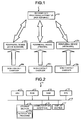
- Fig. 1 is a diagram illustrating the structure of a POS system 1 according to a present embodiment.
- the POS system 1 comprises a POS terminal 10, a first peripheral device 20a, a second peripheral device 20b, a third peripheral device 20c, a first non-contact charger 30a, a second non-contact charger 30b and a third non-contact charger 30c.
- the POS terminal 10 is an information processing apparatus for carrying out a commodity sales data processing.
- the first peripheral device 20a is, for example, a code scanner which optically reads a commodity code barcoded.
- the first non-contact charger 30a supplies electric power (hereinafter referred to as a power transmission) to the first peripheral device 20a in a non-contact manner.
- the first peripheral device 20a receives the electric power (hereinafter referred to as a power reception) supplied from the first non-contact charger 30a in a non-contact manner.
- the first peripheral device 20a is charged with the received electric power.
- the 'non-contact' refers to the absence of a mechanical connection.
- the 'non-contact' refers to that the non-contact charger 30a is not connected with the peripheral device 20a with a wire or a connector.
- the second peripheral device 20b is, for example, a printer which prints the content of a transaction on a sheet such as a receipt paper to issue a receipt.
- the second non-contact charger 30b transmits electric power to the second peripheral device 20b in a non-contact manner.
- the second peripheral device 20b receives the electric power supplied from the second non-contact charger 30b in a non-contact manner.
- the second peripheral device 20b is charged with the received electric power.
- the third peripheral device 20c is, for example, a keyboard including various operation keys for the user to execute an input operation.
- the third non-contact charger 30c transmits electric power to the third peripheral device 20c in a non-contact manner.
- the third peripheral device 20c receives the electric power supplied from the third non-contact charger 30c in a non-contact manner.
- the third peripheral device 20c is charged with the received electric power.
- the peripheral devices 20a, 20b and 20c are commonly described hereinafter as a peripheral device 20 in a case in which they are not distinguished with each other.
- the non-contact chargers 30a, 30b and 30c are commonly described hereinafter as a non-contact charger 30 in a case in which they are not distinguished with one another.
- the peripheral device 20 is not limited to those described above.
- the POS system 1 may further comprise other devices.
- the POS system 1 may be provided with more than one peripheral device 20 and more than one non-contact charger 30. Further, a plurality of peripheral devices 20 may share one non-contact charger 30.
- Fig. 2 is a block diagram exemplifying the hardware structure of the POS terminal 10.
- the POS terminal 10 comprises a CPU (Central Processing Unit) 11, a ROM (Read Only Memory) 12, a RAM (Random Access Memory) 13 and an RTC (Real Time Clock) 14.
- the CPU 11 collectively controls various operations or each section of the POS terminal 10.
- the ROM 12 stores various programs and data.
- the RAM 13 stores various programs temporarily and various data in a rewritable manner.
- the RTC 14 counts the current date and time
- the CPU 11 is connected with a storage section 15, a communication interface 16 and a display section 17 via a bus line 18.
- the storage section 15 is an auxiliary storage device such as an HDD (Hard Disk Drive) or an SSD (Solid State Drive) .
- the storage section 15 stores various programs executed by the CPU 11. Specifically, the storage section 15 stores, for example, a notification program PR1 which is a program for notifying the charging state of the peripheral device 20.
- the communication interface 16 is wirelessly connected with the peripheral device 20. Specifically, the communication interface 16 communicates according to a standard such as a Bluetooth (Registered Trademark) . Further, the communication interface 16 may adopt another standard other than Bluetooth. For example, the communication interface 16 may communicate according to a standard such as a Wireless Fidelity (Registered Trademark).
- a standard such as a Bluetooth (Registered Trademark)
- a Wireless Fidelity (Registered Trademark).
- the display section 17 is, for example, a liquid crystal display.
- the display section 17 displays various kinds of information such as the commodity name and the price of a commodity the sales of which is registered and a total amount and a change amount of one transaction the settlement of which is declared.
- the display section 17 may be provided with a touch panel.
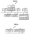
- Fig. 3 is a block diagram exemplifying the hardware structure of the peripheral device 20.
- the peripheral device 20 comprises a CPU 21, a ROM 22, a RAM 23 and an RTC 24.
- the CPU 21 collectively controls various operations and each section of the peripheral device 20.
- the ROM 22 stores various data and programs such as a firmware for controlling the peripheral device 20.
- the ROM 22 stores, for example, a charge-monitoring program PR2 which is a program for monitoring the charging state of the peripheral device 20.
- the RAM 23 stores various programs temporarily and various data in a rewritable manner.
- the RTC 24 counts the current date and time.
- the CPU 21 is connected with a communication interface 25, a secondary battery 26 and a non-contact power reception section 27 via a bus line 28.
- the communication interface 25 is wirelessly connected with the POS terminal 10. Specifically, the communication interface 25 communicates according to a standard such as Bluetooth. Further, the communication interface 25 may adopt another standard other than Bluetooth, for example, the communication interface 25 may communicate according to a standard such as Wireless Fidelity. In the present embodiment, the communication interface 25 adopts the same standard as the communication interface 16 of the POS terminal 10.
- the secondary battery 26 is capable to be charged to store electricity.
- the secondary battery 26 supplies electric power to each section of the peripheral device 20.
- the secondary battery 26 is, for example, a lithium ion battery. Further, the secondary battery 26 may be another kind of battery other than lithium ion battery.
- the non-contact power reception section 27 serving as a power reception section receives the electric power transmitted from the non-contact charger 30 in a non-contact manner.
- the non-contact power reception section 27 rectifies the received electric power.
- the non-contact power reception section 27 charges the secondary battery 26 with the rectified electric power.
- the non-contact power supply system uses a well-known technology.
- the non-contact power supply system may be an electromagnetic induction system, a magnetic resonance system or another system.
- the electromagnetic induction system refers to a system in which electric power is supplied in a non-contact manner with the use of the electromagnetic induction.
- coils are arranged at both a power transmission side from which electric power is supplied and a power reception side which receives the supplied electric power.
- the coils at the power transmission side and those at the power reception side are arranged in side by side manner. If being supplied with electric power, the coils at the power transmission side generate magnetic flux in the inside of the coils. Since the coils at the power reception side are arranged at an adjacent position facing the coils at the power transmission side, magnetic flux also goes through the inside of the coils at the power reception side to generate an induced current.
- the coils at the power transmission side can supply electric power to the coils at the power reception side in a non-contact manner.
- the power supply efficiency is reduced if a positional deviation between the coils at the power transmission side and the power reception side occurs. This is because that the electromagnetic induction system generates the induced current in the coils at the power reception side, using the magnetic flux generated in the coils at the power transmission side.
- the non-contact power reception section 27 comprises a received power detection circuit 271 for detecting the receiving condition of the electric power transmitted in a non-contact manner from the non-contact charger 30. Specifically, the received power detection circuit 271 detects the quantity of the electric power received in a non-contact manner from the non-contact charger 30 in each unit time.
- the received power detection circuit 271 determines the state of non-contact power supply according to the detected quantity of the electric power received in each unit time. If the detected quantity of the electric power received in each unit time is greater than a first threshold value, the received power detection circuit 271 determines that the state of non-contact power supply is good. If the detected quantity of the electric power received in each unit time is smaller than the first threshold value but greater than a second threshold value, the received power detection circuit 271 determines that the state of non-contact power supply is poor. If the detected quantity of the electric power received in each unit time is smaller than the second threshold value, the received power detection circuit 271 determines that the state of non-contact power supply is bad.
- Fig. 4 is a block diagram exemplifying the hardware structure of the non-contact charger 30. As shown in Fig. 4 , in the non-contact charger 30, a power source section 31 is connected with a non-contact power transmission section 32 through a wire 33.
- the power source section 31 receives electric power supplied via a power cable (not shown).
- the power source section 31 rectifies the supplied electric power.
- the power source section 31 supplies the rectified electric power to the non-contact power transmission section 32.
- the non-contact power transmission section 32 transmits the electric power supplied from the power source section 31 to the peripheral device 20 in a non-contact manner.
- the non-contact system is the same as that in the peripheral device 20.
- Fig. 5 is a diagram exemplifying the arrangement of the peripheral device 20 at a proper position.
- Fig. 6 is a diagram exemplifying the arrangement of the peripheral device 20 at an improper position.
- a concentric circle 301 is drawn on the front or upper surface of the non-contact charger 30 shown in Fig. 5 and Fig. 6 . As shown in Fig. 5 , if being placed at the center of the concentric circle 301, the peripheral device 20 can receive the electric power transmitted from the non-contact power transmission section 32. As shown in Fig.
- the peripheral device 20 if the peripheral device 20 is arranged at a position away from the center of the concentric circle 301, then the electric power transmitted to the peripheral device 20 is decreased according to the distance. Consequentially, the non-contact power reception section 27 of the peripheral device 20 cannot receive all or part of the electric power transmitted from the non-contact power transmission section 32 of the non-contact charger 30. Thus, it is important to arrange the peripheral device 20 at a proper position of the non-contact charger 30.
- the proper position refers to a position where the magnetic flux generated by the non-contact charger 30 causes the non-contact power reception section 27 to generate an induced current. That is, the proper position refers to a position where the non-contact power reception section 27 of the peripheral device 20 is adjacent to the center of the concentric circle 301.
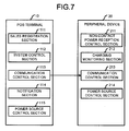
- Fig. 7 is a diagram illustrating the functional component of the POS system 1.
- the POS terminal 10 comprises, as functional sections, a sales registration section 111, a system control section 112, a communication control section 113, a notification section 114 and a power source control section 115.
- each functional section is generated on the RAM 13 through executing the notification program PR1 stored in the storage section 15 by the CPU 11 of the POS terminal 10.
- the sales registration section 111 carries out a sales registration processing for a commodity (sales object) relating to one transaction. Specifically, the sales registration section 111 carries out the sales registration processing by recording the commodity codes, the prices and the sales quantities input through the peripheral device 20a serving as a code scanner and the peripheral device 20c serving as a keyboard in a sales master file. Moreover, the sales registration section 111 causes the peripheral device 20b serving as a printer to print the content of the sales registration.
- the system control section 112 controls the non-contact power supply system relating to the POS system 1.
- the system control section 112 generates monitoring request information and monitoring stop information to monitor the state of the non-contact power supply for the peripheral device 20.
- the monitoring request information refers to a request for monitoring the quantity of the electric power received in a non-contact manner in each unit time.
- the monitoring stop information refers to a request for stopping monitoring the quantity of the electric power received in a non-contact manner in each unit time.
- the POS terminal 10 becomes a state in which the peripheral device 20 is not used if the sales registration processing is ended.
- the communication control section 113 outputs the monitoring request information to the peripheral device 20 when the sales registration processing is ended.
- the peripheral device 20a serving as a code scanner reads a commodity code attached to a commodity in a sales registration processing
- the peripheral device 20a serving as the code scanner cannot receive the electric power transmitted from the non-contact charger 30 in the sales registration processing. Therefore, the POS terminal 10 gives an error notice in which the monitoring to the non-contact power supply is not stopped in the sales registration processing.
- the communication control section 113 outputs the monitoring request information to the peripheral device 20 if the sales registration processing is ended. Moreover, the communication control section 113 outputs the monitoring stop information to the peripheral device 20 if a sales registration processing is started.
- the communication control section 113 controls, via the communication interface 16, the communication with the peripheral device 20 wirelessly connected with the POS terminal 10.
- the communication control section 113 controls the communication with a peripheral device 20 which is paired with the POS terminal 10.
- the 'pairing' refers to a processing in which a peripheral device 20 and the POS terminal 10 are associated with each other so that it is ensured that the POS terminal 10 does not communicate in error with an irrelevant device nearby the POS terminal 10.
- the communication control section 113 sends the monitoring request information or the monitoring stop information to the one or more peripheral devices 20 of the POS system 1.
- the communication control section 113 outputs the monitoring request information or the monitoring stop information to the peripheral devices 20a, 20b and 20c.
- the communication control section 113 receives charging state information from the peripheral device 20.
- the communication control section 113 (input module) receives the input of the charging state information output from the peripheral device 20.
- the charging state information conveys the state of the non-contact power supply for the peripheral device 20 which outputs the charging state information.
- the charging state information includes the state of non-contact power supply, the residual amount of charge and a peripheral device code.
- the state of non-contact power supply indicates the quantity of the electric power received by the peripheral device 20 from the non-contact charger 30 in a non-contact manner in each unit time.
- the residual amount of charge indicates the residual amount of charge which can be supplied to the secondary battery 26 of the peripheral device 20.
- the peripheral device code is identification information capable of identifying the peripheral device 20 which outputs the charging state information.
- the notification section 114 notifies the state of the non-contact power supply for the peripheral device 20.
- the notification section 114 (notification module) notifies the state of the non-contact power supply for the peripheral device 20 if the communication control section 113 receives the input of the charging state information. Specifically, the notification section 114 generates a notification screen if the input of the charging state information is received. The notification section 114 displays the notification screen on the display section 17.
- Fig. 8 is a diagram exemplifying a notification screen G1.
- the notification screen G1 notifies that the quantity of the electric power received by the peripheral device 20 in a non-contact power supply manner is smaller than a threshold value.
- the notification screen G1 shown in Fig. 8 exemplifies, if the input of charging state information is received, that 'the state of non-contact power supply: bad, the residual amount of charge: 60% and peripheral device code: code scanner' .
- the notification screen G1 shown in Fig. 8 displays a message 'charging may not be established' to give a notice.
- the notification screen G1 includes a correction request screen G11.
- the correction request screen G11 is used to request the correction of the arrangement position of the peripheral device 20.
- the correction request screen G11 shown in Fig. 8 displays a message 'move to the center of the circle please' and an image thereof.
- the notification section 114 may change the notification content depending on the quantity of the electric power received in each unit time indicated by the state of non-contact power supply. For example, the notification section 114 changes the message or image displayed on the notification screen G1 according to the poor or bad state of non-contact power supply. Alternatively, the notification section 114 displays the notification screen G1 on the whole screen of the display section 17 if the state of non-contact power supply is bad. If the state of non-contact power supply is poor, the notification section 114 may display a mark, an icon or characters representing the poor state of non-contact power supply on a part of the display section 17.
- the notification section 114 may notify the state of non-contact power supply regardless of the quantity of the electric power received in each unit time indicated by the non-contact power supply state. Specifically, the notification section 114 displays the notification screen G1 on the whole or a part of the display section 17 if the charging state information is input. Alternatively, the notification section 114 may continuously display a mark, an icon or characters representing the content of the charging state information on a part of the display section 17. In this way, the operator can confirm whether the peripheral device 20 is arranged at a proper position.
- the power source control section 115 controls the shutdown processing of the POS terminal 10.
- the power source control section 115 stops the POS terminal 10 through a shutdown processing if a request for a shutdown processing is input.
- the peripheral device 20 comprises, as functional sections, a non-contact power reception control section 211, a charging monitoring section 212, a communication control section 213 and a power source control section 214.
- the CPU 21 of the peripheral device 20 generates each functional section on the RAM 23 by executing a charging monitoring program PR2 stored in the ROM 22.
- the non-contact power reception control section 211 controls the non-contact power supply for the peripheral device 20.
- the non-contact power reception control section 211 receives the electric power transmitted from non-contact charger 30 through the non-contact power reception section 27. Moreover, the non-contact power reception control section 211 charges the secondary battery 26 with the received electric power.
- the charging monitoring section 212 (monitoring module) monitors the electric power received from the non-contact charger 30 through the non-contact power reception section 27. Moreover, the charging monitoring section 212 generates charging state information.
- the charging monitoring section 212 monitors the quantity of the electric power received in a non-contact manner if the input of the monitoring request information output from the POS terminal 10 is received. Moreover, if the input of the monitoring stop information output from the POS terminal 10 is received, the charging monitoring section 212 stops monitoring the electric power received in a non-contact manner. In this way, by using the charging monitoring section 212, the information processing apparatus prevents the giving of an error notice in a case where non-contact power supply is not established.
- the charging monitoring section 212 generates charging state information if the poor or bad state of non-contact power supply is not eliminated until a setting time elapses.
- the charging monitoring section 212 sets initial value for a timer if the input of the monitoring request information is received. Moreover, the charging monitoring section 212 starts the timer. If the state of non-contact power supply is good, the charging monitoring section 212 sets initial value for the timer again. On the other hand, if the state of non-contact power supply is poor or bad, the charging monitoring section 212 keeps the timer counting. The charging monitoring section 212 generates charging state information if the timer value counts the initial value.
- the charging monitoring section 212 measures the residual amount of charge which is being supplied to the secondary battery 26. Moreover, the charging monitoring section 212 generates charging state information including the state of non-contact power supply, the residual amount of charge and a peripheral device code representing a peripheral device.
- the communication control section 213 controls the communication with the POS terminal 10 via the communication interface 25. Specifically, the communication control section 213 sends the charging monitoring information to the POS terminal 10. If the quantity of the electric power received is below a first threshold value, the communication control section 213 serving as an output module outputs the charging state information generated by the charging monitoring section 212. Further, the communication control section 213 receives the monitoring request information or monitoring stop information from the POS terminal 10. The communication control section 213 serving as an input module receives the input of the monitoring request information representing a request for the monitoring on non-contact power supply.
- the power source control section 214 controls the shutdown processing of the peripheral device 20.
- the power source control section 214 stops the peripheral device 20 through the shutdown processing if a request for a shutdown processing is input.
- a notification processing is described which is carried out by the CPU 11 of the POS terminal 10 according to the foregoing embodiment according to the notification program PR1.
- the notification processing is carried out to notify the state of the charging of the peripheral device 20.
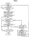
- Fig. 9 is a flowchart illustrating the procedure of a notification processing carried out by the CPU 11 of the POS terminal 10 according to the notification program PR1.
- the sales registration section 111 of the POS terminal 10 determines whether or not the sales registration processing according to one transaction is ended (Act S11) . If the sales registration processing is not ended (No in Act S11), the sales registration section 111 of the POS terminal 10 waits for a notification processing.
- the system control section 112 of the POS terminal 10 generates monitoring request information (Act S12). Then, the communication control section 113 of the POS terminal 10 outputs the monitoring request information to the peripheral device 20 (Act S13) .
- the communication control section 113 of the POS terminal 10 determines whether or not the input of charging state information is received (Act S14). If the input of charging state information is received (Yes in Act S14), the notification section 114 of the POS terminal 10 displays the notification screen G1 (Act S15). Moreover, the CPU 11 of the POS terminal 10 proceeds to the processing in Act S14.
- the sales registration section 111 of the POS terminal 10 determines whether or not a sales registration processing is started (Act S16).
- the system control section 112 of the POS terminal 10 If a sales registration processing is started (Yes in Act S16), the system control section 112 of the POS terminal 10 generates monitoring stop information (Act S17). The communication control section 113 of the POS terminal 10 outputs the monitoring stop information to the peripheral device 20 (Act S18). Moreover, the CPU 11 of the POS terminal 10 proceeds to the processing in Act S11.
- the power source control section 115 of the POS terminal 10 determines whether or not the POS terminal 10 is shut down (Act S19). If the POS terminal 10 is not shut down (No in Act S19), the CPU 11 of the POS terminal 10 proceeds to the processing in Act S14.
- the charging monitoring processing refers to a processing of monitoring the state of the charging of the peripheral device 20.
- Fig. 10 is a flowchart illustrating the procedure of a charging monitoring processing carried out by the CPU 21 of the peripheral device 20 according to the charging monitoring program PR2.
- the communication control section 213 of the peripheral device 20 determines whether or not the input of monitoring request information is received (Act S21) . If the input of monitoring request information is not received (No in Act S21), the CPU 21 of the peripheral device 20 waits for a charging monitoring processing.
- the charging monitoring section 212 of the peripheral device 20 sets initial value for the timer (Act S22). Then, the charging monitoring section 212 of the peripheral device 20 determines whether or not the state of non-contact power supply is good (Act S23).
- the charging monitoring section 212 of the peripheral device 20 determines whether or not a setting time elapses (Act S24). If the setting time dose not elapse (No in Act S24), the CPU 21 of the peripheral device 20 proceeds to the processing in Act S23.
- the charging monitoring section 212 of the peripheral device 20 measures the residual amount of charge which is being supplied to the secondary battery 26 (Act S25). Sequentially, the charging monitoring section 212 of the peripheral device 20 generates charging state information including the state of non-contact power supply, the residual amount of charge and a peripheral device code representing the peripheral device 20 (Act S26).
- the communication control section 213 of the peripheral device 20 outputs the charging state information to the POS terminal 10 (Act S27). Moreover, the CPU 21 of the peripheral device 20 proceeds to the processing in Act S28.
- the communication control section 213 of the peripheral device 20 determines whether or not the input of monitoring stop information is received (Act S28). If the input of monitoring stop information is not received (No in Act S28), the CPU 21 of the peripheral device 20 proceeds to the processing in Act S22.
- the power source control section 214 of the peripheral device 20 determines whether or not the peripheral device 20 is shut down (Act S29). If the peripheral device 20 is not shut down (No in Act S29), the CPU 21 of the peripheral device 20 proceeds to the processing in Act S21.
- the POS terminal 10 can receive, from the peripheral device 20 corresponding to the POS terminal 10, charging state information representing the state of non-contact power supply for the peripheral device 20. Moreover, if receiving the charging state information, the POS terminal 10 notifies the non-contact power supply information of the peripheral device 20. In this way, the POS terminal 10 can notify the state of the non-contact power supply for the peripheral device 20.
- the notification section 114 of the POS terminal 10 notifies the state of the non-contact power supply for the peripheral device 20 by displaying the notification screen G1 on the display section 17.
- the notification section 114 may notify the state of the non-contact power supply for the peripheral device 20 in another way different from displaying the notification screen G1.
- the notification section 114 may notify that the state of non-contact power supply is poor or bad with voice.
- the state of non-contact power supply contained in the charging state information is determined by the received power detection circuit 271.
- the state of non-contact power supply contained in the charging state information may also be determined by the CPU 21 of the peripheral device 20.
- the received power detection circuit 271 notifies the CPU 21 of the quantity of the electric power received in each unit time. Then, the CPU 21 determines the state of non-contact power supply according to the received electric power quantity.
- a threshold value relating to the determination on the state of non-contact power supply state can be set to any value.
- the programs executed by each device according to the foregoing embodiments or variations of the foregoing embodiments are pre-compiled in the storage medium (e.g. a ROM or a storage section) of the device; however, the present invention is not limited to this.
- the programs may be recorded in a computer-readable recording medium such as a CD-ROM, a FD (Floppy Disk), a CD-R, and a DVD (Digital Versatile Disk) as installable or executable files.
- the storage medium which is not limited to a medium independent from a computer or assembled in a system, further includes a storage medium for storing or temporarily storing a program transferred via and downloaded through an LAN or Internet.
- the programs executed by each device according to the foregoing embodiments or variations of the foregoing embodiments are stored in a computer connected with a network such as the Internet and downloaded in the apparatus, or are provided or issued by a network such as the Internet.
Landscapes
- Engineering & Computer Science (AREA)
- Theoretical Computer Science (AREA)
- Physics & Mathematics (AREA)
- General Physics & Mathematics (AREA)
- Computer Networks & Wireless Communication (AREA)
- Power Engineering (AREA)
- General Engineering & Computer Science (AREA)
- Signal Processing (AREA)
- Charge And Discharge Circuits For Batteries Or The Like (AREA)
- Cash Registers Or Receiving Machines (AREA)
Abstract
Description
- Embodiments described herein relate generally to an information processing apparatus and a peripheral device which is used by the information processing apparatus.
- A non-contact power supply system which transfers power without using a power cable has been used in recent years. The non-contact power supply system is capable of supplying electric power to a secondary battery carried on a personal computer, an AV (Audio Visual) device and the like with the use of the resonance phenomenon of an electromagnetic field.
- Further, it is researched to introduce such a non-contact power supply system into a peripheral device of a POS (Point Of Sale) system. In a case in which a non-contact power supply system is introduced into a POS system, the peripheral device cannot be charged if a non-contact charger is not placed at a chargeable position. However, there is a case in which an operator of the POS system neglects or unintentionally forgets to place the peripheral device at a chargeable position because he/she always gives priority to sales-register the commodities.
-
-
Fig. 1 is a diagram illustrating the structure of a POS system according to an embodiment; -
Fig. 2 is a block diagram exemplifying the hardware structure of a POS terminal; -
Fig. 3 is a block diagram exemplifying the hardware structure of a peripheral device; -
Fig. 4 is a block diagram exemplifying the hardware structure of a non-contact charger; -
Fig. 5 is an illustration diagram exemplifying the arrangement of the peripheral device at a proper position; -
Fig. 6 is an illustration diagram exemplifying the arrangement of the peripheral device at an improper position; -
Fig. 7 is a diagram illustrating the functional component of a POS system; -
Fig. 8 is a diagram exemplifying a notification screen; -
Fig. 9 is a flowchart illustrating the procedure of a notification processing; and -
Fig. 10 is a flowchart illustrating the procedure of a charge-monitoring processing. - In accordance with an embodiment, an information processing apparatus comprises a communication control module, an input module and a notification module. The communication control module controls the communication with a peripheral device which is associated with the information processing apparatus. The input module receives the input of the charging state information output from the peripheral device, which indicates the state of non-contact power supply to the peripheral device with a non-contact manner in which no mechanical connection is taken with the peripheral device. The notification module notifies, if the input module receives the input of the charging state information, the state of the non-contact power supply for the peripheral device.
- Preferably, the information processing apparatus further comprises a display section, wherein the notification module displays, on the display section, a screen showing that the quantity of the electric power received by the peripheral device with the non-contact power supply is below a threshold value.
- Preferably, the communication control module outputs monitoring request information for requesting the monitoring on the non-contact power supply for the peripheral device if the information processing apparatus becomes a state in which it does not use the peripheral device.
- Preferably, the communication control device outputs monitoring request information for requesting the monitoring on the non-contact power supply for the peripheral device if the information processing apparatus becomes a state in which it does not use the peripheral device.
- Preferably, the input module receives the input of the charging state information indicating the quantity of the electric power received in each unit time, and the notification module changes content of the notification according to the quantity of the electric power received.
- Preferably, the input module receives the input of the charging state information including identification information capable of identifying the peripheral device which outputs the charging state information and the notification module notifies the identification information.
- The present invention also relates to a peripheral device which is used by an information processing apparatus. This peripheral device comprises: a power reception section configured to receive electric power transmitted in non-contact manner in which no mechanical connection is taken; a monitoring module configured to monitor the electric power received via the power reception section; and an output module configured to output charging state information which indicates the state of the non-contact power supply containing information indicating the quantity of the electric power monitored by the monitoring module to the information processing apparatus.
- Accordingly, the present invention provides a stable power supply system to peripheral devices especially for peripheral devices used in a dynamic place where a user must pay attention at once to a lot of things.
- Hereinafter, the information processing apparatus and the peripheral device according to the present embodiment are described below in detail with reference to the accompanying drawings. Descriptions hereafter are embodiments of the information processing apparatus and the peripheral device, and thus the structures and specifications thereof are not limited. The present embodiment is an example of applying a non-contact power supply system to a POS system which is introduced into a store such as a supermarket to carry out the sales registration and settlement of the commodities according to one transaction.
-
Fig. 1 is a diagram illustrating the structure of a POS system 1 according to a present embodiment. The POS system 1 comprises aPOS terminal 10, a firstperipheral device 20a, a secondperipheral device 20b, a thirdperipheral device 20c, a first non-contactcharger 30a, a second non-contactcharger 30b and a thirdnon-contact charger 30c. - The
POS terminal 10 is an information processing apparatus for carrying out a commodity sales data processing. The firstperipheral device 20a is, for example, a code scanner which optically reads a commodity code barcoded. The firstnon-contact charger 30a supplies electric power (hereinafter referred to as a power transmission) to the firstperipheral device 20a in a non-contact manner. The firstperipheral device 20a receives the electric power (hereinafter referred to as a power reception) supplied from the firstnon-contact charger 30a in a non-contact manner. The firstperipheral device 20a is charged with the received electric power. The 'non-contact' refers to the absence of a mechanical connection. For example, the 'non-contact' refers to that thenon-contact charger 30a is not connected with theperipheral device 20a with a wire or a connector. - The second
peripheral device 20b is, for example, a printer which prints the content of a transaction on a sheet such as a receipt paper to issue a receipt. The secondnon-contact charger 30b transmits electric power to the secondperipheral device 20b in a non-contact manner. The secondperipheral device 20b receives the electric power supplied from the secondnon-contact charger 30b in a non-contact manner. Moreover, the secondperipheral device 20b is charged with the received electric power. - The third
peripheral device 20c is, for example, a keyboard including various operation keys for the user to execute an input operation. The thirdnon-contact charger 30c transmits electric power to the thirdperipheral device 20c in a non-contact manner. The thirdperipheral device 20c receives the electric power supplied from the thirdnon-contact charger 30c in a non-contact manner. Moreover, the thirdperipheral device 20c is charged with the received electric power. - The
peripheral devices peripheral device 20 in a case in which they are not distinguished with each other. Thenon-contact chargers non-contact charger 30 in a case in which they are not distinguished with one another. Further, theperipheral device 20 is not limited to those described above. The POS system 1 may further comprise other devices. The POS system 1 may be provided with more than oneperipheral device 20 and more than onenon-contact charger 30. Further, a plurality ofperipheral devices 20 may share onenon-contact charger 30. - Sequentially, the hardware structure of each foregoing device is described.
- The
POS terminal 10 is described first.Fig. 2 is a block diagram exemplifying the hardware structure of thePOS terminal 10. As shown inFig. 2 , thePOS terminal 10 comprises a CPU (Central Processing Unit) 11, a ROM (Read Only Memory) 12, a RAM (Random Access Memory) 13 and an RTC (Real Time Clock) 14. TheCPU 11 collectively controls various operations or each section of thePOS terminal 10. TheROM 12 stores various programs and data. TheRAM 13 stores various programs temporarily and various data in a rewritable manner. TheRTC 14 counts the current date and time - The
CPU 11 is connected with astorage section 15, acommunication interface 16 and adisplay section 17 via abus line 18. - The
storage section 15 is an auxiliary storage device such as an HDD (Hard Disk Drive) or an SSD (Solid State Drive) . Thestorage section 15 stores various programs executed by theCPU 11. Specifically, thestorage section 15 stores, for example, a notification program PR1 which is a program for notifying the charging state of theperipheral device 20. - The
communication interface 16 is wirelessly connected with theperipheral device 20. Specifically, thecommunication interface 16 communicates according to a standard such as a Bluetooth (Registered Trademark) . Further, thecommunication interface 16 may adopt another standard other than Bluetooth. For example, thecommunication interface 16 may communicate according to a standard such as a Wireless Fidelity (Registered Trademark). - The
display section 17 is, for example, a liquid crystal display. Thedisplay section 17 displays various kinds of information such as the commodity name and the price of a commodity the sales of which is registered and a total amount and a change amount of one transaction the settlement of which is declared. Thedisplay section 17 may be provided with a touch panel. - Next, the
peripheral device 20 is described.Fig. 3 is a block diagram exemplifying the hardware structure of theperipheral device 20. As shown inFig. 3 , theperipheral device 20 comprises aCPU 21, aROM 22, aRAM 23 and anRTC 24. TheCPU 21 collectively controls various operations and each section of theperipheral device 20. TheROM 22 stores various data and programs such as a firmware for controlling theperipheral device 20. Specifically, theROM 22 stores, for example, a charge-monitoring program PR2 which is a program for monitoring the charging state of theperipheral device 20. TheRAM 23 stores various programs temporarily and various data in a rewritable manner. TheRTC 24 counts the current date and time. - The
CPU 21 is connected with acommunication interface 25, asecondary battery 26 and a non-contactpower reception section 27 via abus line 28. - The
communication interface 25 is wirelessly connected with thePOS terminal 10. Specifically, thecommunication interface 25 communicates according to a standard such as Bluetooth. Further, thecommunication interface 25 may adopt another standard other than Bluetooth, for example, thecommunication interface 25 may communicate according to a standard such as Wireless Fidelity. In the present embodiment, thecommunication interface 25 adopts the same standard as thecommunication interface 16 of thePOS terminal 10. - The
secondary battery 26 is capable to be charged to store electricity. Thesecondary battery 26 supplies electric power to each section of theperipheral device 20. Thesecondary battery 26 is, for example, a lithium ion battery. Further, thesecondary battery 26 may be another kind of battery other than lithium ion battery. - The non-contact
power reception section 27 serving as a power reception section receives the electric power transmitted from thenon-contact charger 30 in a non-contact manner. The non-contactpower reception section 27 rectifies the received electric power. Moreover, the non-contactpower reception section 27 charges thesecondary battery 26 with the rectified electric power. The non-contact power supply system uses a well-known technology. The non-contact power supply system may be an electromagnetic induction system, a magnetic resonance system or another system. - The electromagnetic induction system refers to a system in which electric power is supplied in a non-contact manner with the use of the electromagnetic induction. In the electromagnetic induction system, coils are arranged at both a power transmission side from which electric power is supplied and a power reception side which receives the supplied electric power. Moreover, in the electromagnetic induction system, the coils at the power transmission side and those at the power reception side are arranged in side by side manner. If being supplied with electric power, the coils at the power transmission side generate magnetic flux in the inside of the coils. Since the coils at the power reception side are arranged at an adjacent position facing the coils at the power transmission side, magnetic flux also goes through the inside of the coils at the power reception side to generate an induced current. Consequentially, the coils at the power transmission side can supply electric power to the coils at the power reception side in a non-contact manner. There is a case in which the power supply efficiency is reduced if a positional deviation between the coils at the power transmission side and the power reception side occurs. This is because that the electromagnetic induction system generates the induced current in the coils at the power reception side, using the magnetic flux generated in the coils at the power transmission side.
- The non-contact
power reception section 27 comprises a receivedpower detection circuit 271 for detecting the receiving condition of the electric power transmitted in a non-contact manner from thenon-contact charger 30. Specifically, the receivedpower detection circuit 271 detects the quantity of the electric power received in a non-contact manner from thenon-contact charger 30 in each unit time. - The received
power detection circuit 271 determines the state of non-contact power supply according to the detected quantity of the electric power received in each unit time. If the detected quantity of the electric power received in each unit time is greater than a first threshold value, the receivedpower detection circuit 271 determines that the state of non-contact power supply is good. If the detected quantity of the electric power received in each unit time is smaller than the first threshold value but greater than a second threshold value, the receivedpower detection circuit 271 determines that the state of non-contact power supply is poor. If the detected quantity of the electric power received in each unit time is smaller than the second threshold value, the receivedpower detection circuit 271 determines that the state of non-contact power supply is bad. - Next, the
non-contact charger 30 is described.Fig. 4 is a block diagram exemplifying the hardware structure of thenon-contact charger 30. As shown inFig. 4 , in thenon-contact charger 30, apower source section 31 is connected with a non-contactpower transmission section 32 through awire 33. - The
power source section 31 receives electric power supplied via a power cable (not shown). Thepower source section 31 rectifies the supplied electric power. Moreover, thepower source section 31 supplies the rectified electric power to the non-contactpower transmission section 32. - The non-contact
power transmission section 32 transmits the electric power supplied from thepower source section 31 to theperipheral device 20 in a non-contact manner. In the present embodiment, the non-contact system is the same as that in theperipheral device 20. - In a case in which the
peripheral device 20 is arranged at a proper position, thenon-contact charger 30 transmits electric power to the non-contactpower reception section 27 of theperipheral device 20 through the non-contactpower transmission section 32.Fig. 5 is a diagram exemplifying the arrangement of theperipheral device 20 at a proper position.Fig. 6 is a diagram exemplifying the arrangement of theperipheral device 20 at an improper position. Aconcentric circle 301 is drawn on the front or upper surface of thenon-contact charger 30 shown inFig. 5 and Fig. 6 . As shown inFig. 5 , if being placed at the center of theconcentric circle 301, theperipheral device 20 can receive the electric power transmitted from the non-contactpower transmission section 32. As shown inFig. 6 , if theperipheral device 20 is arranged at a position away from the center of theconcentric circle 301, then the electric power transmitted to theperipheral device 20 is decreased according to the distance. Consequentially, the non-contactpower reception section 27 of theperipheral device 20 cannot receive all or part of the electric power transmitted from the non-contactpower transmission section 32 of thenon-contact charger 30. Thus, it is important to arrange theperipheral device 20 at a proper position of thenon-contact charger 30. The proper position refers to a position where the magnetic flux generated by thenon-contact charger 30 causes the non-contactpower reception section 27 to generate an induced current. That is, the proper position refers to a position where the non-contactpower reception section 27 of theperipheral device 20 is adjacent to the center of theconcentric circle 301. - Sequentially, the functional component of the POS system 1 is described.
Fig. 7 is a diagram illustrating the functional component of the POS system 1. - The functional component of the
POS terminal 10 is described. As shown inFig. 7 , thePOS terminal 10 comprises, as functional sections, asales registration section 111, asystem control section 112, acommunication control section 113, anotification section 114 and a powersource control section 115. Specifically, each functional section is generated on theRAM 13 through executing the notification program PR1 stored in thestorage section 15 by theCPU 11 of thePOS terminal 10. - The
sales registration section 111 carries out a sales registration processing for a commodity (sales object) relating to one transaction. Specifically, thesales registration section 111 carries out the sales registration processing by recording the commodity codes, the prices and the sales quantities input through theperipheral device 20a serving as a code scanner and theperipheral device 20c serving as a keyboard in a sales master file. Moreover, thesales registration section 111 causes theperipheral device 20b serving as a printer to print the content of the sales registration. - The
system control section 112 controls the non-contact power supply system relating to the POS system 1. Thesystem control section 112 generates monitoring request information and monitoring stop information to monitor the state of the non-contact power supply for theperipheral device 20. The monitoring request information refers to a request for monitoring the quantity of the electric power received in a non-contact manner in each unit time. The monitoring stop information refers to a request for stopping monitoring the quantity of the electric power received in a non-contact manner in each unit time. ThePOS terminal 10 becomes a state in which theperipheral device 20 is not used if the sales registration processing is ended. Thus thecommunication control section 113 outputs the monitoring request information to theperipheral device 20 when the sales registration processing is ended. - For example, as the
peripheral device 20a serving as a code scanner reads a commodity code attached to a commodity in a sales registration processing, theperipheral device 20a serving as the code scanner cannot receive the electric power transmitted from thenon-contact charger 30 in the sales registration processing. Therefore, thePOS terminal 10 gives an error notice in which the monitoring to the non-contact power supply is not stopped in the sales registration processing. To avoid the error notice, thecommunication control section 113 outputs the monitoring request information to theperipheral device 20 if the sales registration processing is ended. Moreover, thecommunication control section 113 outputs the monitoring stop information to theperipheral device 20 if a sales registration processing is started. - The communication control section 113 (communication control module) controls, via the
communication interface 16, the communication with theperipheral device 20 wirelessly connected with thePOS terminal 10. In a case in which thecommunication interface 16 communicates according to a standard such as Bluetooth, thecommunication control section 113 controls the communication with aperipheral device 20 which is paired with thePOS terminal 10. The 'pairing' refers to a processing in which aperipheral device 20 and thePOS terminal 10 are associated with each other so that it is ensured that thePOS terminal 10 does not communicate in error with an irrelevant device nearby thePOS terminal 10. - Moreover, the
communication control section 113 sends the monitoring request information or the monitoring stop information to the one or moreperipheral devices 20 of the POS system 1. In the present embodiment, thecommunication control section 113 outputs the monitoring request information or the monitoring stop information to theperipheral devices - Further, the
communication control section 113 receives charging state information from theperipheral device 20. The communication control section 113 (input module) receives the input of the charging state information output from theperipheral device 20. The charging state information conveys the state of the non-contact power supply for theperipheral device 20 which outputs the charging state information. The charging state information includes the state of non-contact power supply, the residual amount of charge and a peripheral device code. The state of non-contact power supply indicates the quantity of the electric power received by theperipheral device 20 from thenon-contact charger 30 in a non-contact manner in each unit time. The residual amount of charge indicates the residual amount of charge which can be supplied to thesecondary battery 26 of theperipheral device 20. The peripheral device code is identification information capable of identifying theperipheral device 20 which outputs the charging state information. - The
notification section 114 notifies the state of the non-contact power supply for theperipheral device 20. The notification section 114 (notification module) notifies the state of the non-contact power supply for theperipheral device 20 if thecommunication control section 113 receives the input of the charging state information. Specifically, thenotification section 114 generates a notification screen if the input of the charging state information is received. Thenotification section 114 displays the notification screen on thedisplay section 17. -
Fig. 8 is a diagram exemplifying a notification screen G1. The notification screen G1 notifies that the quantity of the electric power received by theperipheral device 20 in a non-contact power supply manner is smaller than a threshold value. The notification screen G1 shown inFig. 8 exemplifies, if the input of charging state information is received, that 'the state of non-contact power supply: bad, the residual amount of charge: 60% and peripheral device code: code scanner' . The notification screen G1 shown inFig. 8 displays a message 'charging may not be established' to give a notice. Further, the notification screen G1 includes a correction request screen G11. The correction request screen G11 is used to request the correction of the arrangement position of theperipheral device 20. The correction request screen G11 shown inFig. 8 displays a message 'move to the center of the circle please' and an image thereof. - The
notification section 114 may change the notification content depending on the quantity of the electric power received in each unit time indicated by the state of non-contact power supply. For example, thenotification section 114 changes the message or image displayed on the notification screen G1 according to the poor or bad state of non-contact power supply. Alternatively, thenotification section 114 displays the notification screen G1 on the whole screen of thedisplay section 17 if the state of non-contact power supply is bad. If the state of non-contact power supply is poor, thenotification section 114 may display a mark, an icon or characters representing the poor state of non-contact power supply on a part of thedisplay section 17. - Further, the
notification section 114 may notify the state of non-contact power supply regardless of the quantity of the electric power received in each unit time indicated by the non-contact power supply state. Specifically, thenotification section 114 displays the notification screen G1 on the whole or a part of thedisplay section 17 if the charging state information is input. Alternatively, thenotification section 114 may continuously display a mark, an icon or characters representing the content of the charging state information on a part of thedisplay section 17. In this way, the operator can confirm whether theperipheral device 20 is arranged at a proper position. - The power
source control section 115 controls the shutdown processing of thePOS terminal 10. The powersource control section 115 stops thePOS terminal 10 through a shutdown processing if a request for a shutdown processing is input. - Sequentially, the functional component of the
peripheral device 20 is described. As shown inFig. 7 , theperipheral device 20 comprises, as functional sections, a non-contact powerreception control section 211, a chargingmonitoring section 212, acommunication control section 213 and a powersource control section 214. Specifically, theCPU 21 of theperipheral device 20 generates each functional section on theRAM 23 by executing a charging monitoring program PR2 stored in theROM 22. - The non-contact power
reception control section 211 controls the non-contact power supply for theperipheral device 20. The non-contact powerreception control section 211 receives the electric power transmitted fromnon-contact charger 30 through the non-contactpower reception section 27. Moreover, the non-contact powerreception control section 211 charges thesecondary battery 26 with the received electric power. - The charging monitoring section 212 (monitoring module) monitors the electric power received from the
non-contact charger 30 through the non-contactpower reception section 27. Moreover, the chargingmonitoring section 212 generates charging state information. - The charging
monitoring section 212 monitors the quantity of the electric power received in a non-contact manner if the input of the monitoring request information output from thePOS terminal 10 is received. Moreover, if the input of the monitoring stop information output from thePOS terminal 10 is received, the chargingmonitoring section 212 stops monitoring the electric power received in a non-contact manner. In this way, by using the chargingmonitoring section 212, the information processing apparatus prevents the giving of an error notice in a case where non-contact power supply is not established. - Further, there is a case in which the operator electrically disconnects the
peripheral device 20 from thenon-contact charger 30 temporarily even if the sales registration processing is completed or intentionally takes theperipheral device 20 off thenon-contact charger 30 once the sales registration processing is completed. If such a situation is notified immediately as poor or bad non-contact power supply, then the operator must deal with the troublesome notification. Thus, the chargingmonitoring section 212 generates charging state information if the poor or bad state of non-contact power supply is not eliminated until a setting time elapses. - Specifically, the charging
monitoring section 212 sets initial value for a timer if the input of the monitoring request information is received. Moreover, the chargingmonitoring section 212 starts the timer. If the state of non-contact power supply is good, the chargingmonitoring section 212 sets initial value for the timer again. On the other hand, if the state of non-contact power supply is poor or bad, the chargingmonitoring section 212 keeps the timer counting. The chargingmonitoring section 212 generates charging state information if the timer value counts the initial value. - In this case, the charging
monitoring section 212 measures the residual amount of charge which is being supplied to thesecondary battery 26. Moreover, the chargingmonitoring section 212 generates charging state information including the state of non-contact power supply, the residual amount of charge and a peripheral device code representing a peripheral device. - The
communication control section 213 controls the communication with thePOS terminal 10 via thecommunication interface 25. Specifically, thecommunication control section 213 sends the charging monitoring information to thePOS terminal 10. If the quantity of the electric power received is below a first threshold value, thecommunication control section 213 serving as an output module outputs the charging state information generated by the chargingmonitoring section 212. Further, thecommunication control section 213 receives the monitoring request information or monitoring stop information from thePOS terminal 10. Thecommunication control section 213 serving as an input module receives the input of the monitoring request information representing a request for the monitoring on non-contact power supply. - The power
source control section 214 controls the shutdown processing of theperipheral device 20. The powersource control section 214 stops theperipheral device 20 through the shutdown processing if a request for a shutdown processing is input. - Sequentially, a notification processing is described which is carried out by the
CPU 11 of thePOS terminal 10 according to the foregoing embodiment according to the notification program PR1. The notification processing is carried out to notify the state of the charging of theperipheral device 20. -
Fig. 9 is a flowchart illustrating the procedure of a notification processing carried out by theCPU 11 of thePOS terminal 10 according to the notification program PR1. - First, the
sales registration section 111 of thePOS terminal 10 determines whether or not the sales registration processing according to one transaction is ended (Act S11) . If the sales registration processing is not ended (No in Act S11), thesales registration section 111 of thePOS terminal 10 waits for a notification processing. - On the other hand, if the sales registration processing is ended (Yes in Act S11), the
system control section 112 of thePOS terminal 10 generates monitoring request information (Act S12). Then, thecommunication control section 113 of thePOS terminal 10 outputs the monitoring request information to the peripheral device 20 (Act S13) . - Sequentially, the
communication control section 113 of thePOS terminal 10 determines whether or not the input of charging state information is received (Act S14). If the input of charging state information is received (Yes in Act S14), thenotification section 114 of thePOS terminal 10 displays the notification screen G1 (Act S15). Moreover, theCPU 11 of thePOS terminal 10 proceeds to the processing in Act S14. - On the other hand, if the input of charging state information is not received (No in Act S14), the
sales registration section 111 of thePOS terminal 10 determines whether or not a sales registration processing is started (Act S16). - If a sales registration processing is started (Yes in Act S16), the
system control section 112 of thePOS terminal 10 generates monitoring stop information (Act S17). Thecommunication control section 113 of thePOS terminal 10 outputs the monitoring stop information to the peripheral device 20 (Act S18). Moreover, theCPU 11 of thePOS terminal 10 proceeds to the processing in Act S11. - If a sales registration processing is not started (Act S16: No), the power
source control section 115 of thePOS terminal 10 determines whether or not thePOS terminal 10 is shut down (Act S19). If thePOS terminal 10 is not shut down (No in Act S19), theCPU 11 of thePOS terminal 10 proceeds to the processing in Act S14. - On the other hand, if the
POS terminal 10 is shut down (Yes in Act S19), theCPU 11 of thePOS terminal 10 ends the notification processing. - Next, a charging monitoring processing is described which is carried out by the
CPU 21 of theperipheral device 20 relating to the foregoing embodiment according to the charging monitoring program PR2. The charging monitoring processing refers to a processing of monitoring the state of the charging of theperipheral device 20. -
Fig. 10 is a flowchart illustrating the procedure of a charging monitoring processing carried out by theCPU 21 of theperipheral device 20 according to the charging monitoring program PR2. - First, the
communication control section 213 of theperipheral device 20 determines whether or not the input of monitoring request information is received (Act S21) . If the input of monitoring request information is not received (No in Act S21), theCPU 21 of theperipheral device 20 waits for a charging monitoring processing. - On the other hand, if the input of monitoring request information is received, (Yes in Act S21), then the charging
monitoring section 212 of theperipheral device 20 sets initial value for the timer (Act S22). Then, the chargingmonitoring section 212 of theperipheral device 20 determines whether or not the state of non-contact power supply is good (Act S23). - If the state of non-contact power supply is poor (No in Act S23), then the charging
monitoring section 212 of theperipheral device 20 determines whether or not a setting time elapses (Act S24). If the setting time dose not elapse (No in Act S24), theCPU 21 of theperipheral device 20 proceeds to the processing in Act S23. - On the other hand, if the setting time elapses (Yes in Act S24), the charging
monitoring section 212 of theperipheral device 20 measures the residual amount of charge which is being supplied to the secondary battery 26 (Act S25). Sequentially, the chargingmonitoring section 212 of theperipheral device 20 generates charging state information including the state of non-contact power supply, the residual amount of charge and a peripheral device code representing the peripheral device 20 (Act S26). - Sequentially, the
communication control section 213 of theperipheral device 20 outputs the charging state information to the POS terminal 10 (Act S27). Moreover, theCPU 21 of theperipheral device 20 proceeds to the processing in Act S28. - If the state of non-contact power supply is good (Yes in Act 23), the
communication control section 213 of theperipheral device 20 determines whether or not the input of monitoring stop information is received (Act S28). If the input of monitoring stop information is not received (No in Act S28), theCPU 21 of theperipheral device 20 proceeds to the processing in Act S22. - On the other hand, if the input of monitoring stop information is received (Yes in Act S28), then the power
source control section 214 of theperipheral device 20 determines whether or not theperipheral device 20 is shut down (Act S29). If theperipheral device 20 is not shut down (No in Act S29), theCPU 21 of theperipheral device 20 proceeds to the processing in Act S21. - On the other hand, if the
peripheral device 20 is shut down (Yes in Act S29), theCPU 21 of theperipheral device 20 ends the charging monitoring processing. - As stated above, according to the POS system 1 of the present embodiment, the
POS terminal 10 can receive, from theperipheral device 20 corresponding to thePOS terminal 10, charging state information representing the state of non-contact power supply for theperipheral device 20. Moreover, if receiving the charging state information, thePOS terminal 10 notifies the non-contact power supply information of theperipheral device 20. In this way, thePOS terminal 10 can notify the state of the non-contact power supply for theperipheral device 20. - While certain embodiments have been described, these embodiments have been presented by way of example only, and are not intended to limit the scope of the invention. Indeed, the novel embodiments described herein may be embodied in a variety of other forms; furthermore, various omissions, substitutions and changes in the form of the embodiments described herein may be made without departing from the frameworkof the invention. The accompanying claims and their equivalents are intended to cover such forms or modifications as would fall within the scope of the invention.
- Further, in the foregoing embodiment, the
notification section 114 of thePOS terminal 10 notifies the state of the non-contact power supply for theperipheral device 20 by displaying the notification screen G1 on thedisplay section 17. However, thenotification section 114 may notify the state of the non-contact power supply for theperipheral device 20 in another way different from displaying the notification screen G1. For example, thenotification section 114 may notify that the state of non-contact power supply is poor or bad with voice. - Further, it is described in the foregoing embodiment that the state of non-contact power supply contained in the charging state information is determined by the received
power detection circuit 271. However, the state of non-contact power supply contained in the charging state information may also be determined by theCPU 21 of theperipheral device 20. In such a case, the receivedpower detection circuit 271 notifies theCPU 21 of the quantity of the electric power received in each unit time. Then, theCPU 21 determines the state of non-contact power supply according to the received electric power quantity. Moreover, as theCPU 21 uses software for the determination, a threshold value relating to the determination on the state of non-contact power supply state can be set to any value. - The programs executed by each device according to the foregoing embodiments or variations of the foregoing embodiments are pre-compiled in the storage medium (e.g. a ROM or a storage section) of the device; however, the present invention is not limited to this. The programs may be recorded in a computer-readable recording medium such as a CD-ROM, a FD (Floppy Disk), a CD-R, and a DVD (Digital Versatile Disk) as installable or executable files. Further, the storage medium, which is not limited to a medium independent from a computer or assembled in a system, further includes a storage medium for storing or temporarily storing a program transferred via and downloaded through an LAN or Internet.
- Further, the programs executed by each device according to the foregoing embodiments or variations of the foregoing embodiments are stored in a computer connected with a network such as the Internet and downloaded in the apparatus, or are provided or issued by a network such as the Internet.
Claims (7)
- An information processing apparatus, comprising:a communication control module configured to control the communication with a peripheral device which is associated with the information processing apparatus;an input module configured to receive the input of the charging state information, output from the peripheral device, which indicates the state of non-contact power supply to the peripheral device with a non-contact manner in which no mechanical connection is taken with the peripheral device; anda notification module configured to notify, if the input module receives the input of the charging state information, the state of the non-contact power supply for the peripheral device.
- The information processing apparatus according to claim 1, further comprising a display section, wherein the notification module displays, on the display section, a screen showing that the quantity of the electric power received by the peripheral device with the non-contact power supply is below a threshold value.
- The information processing apparatus according to claim 1 or 2, wherein the communication control module outputs monitoring request information for requesting the monitoring on the non-contact power supply for the peripheral device if the information processing apparatus becomes a state in which it does not use the peripheral device.
- The information processing apparatus according to claim 2 or 3, wherein the communication control device outputs monitoring request information for requesting the monitoring on the non-contact power supply for the peripheral device if the information processing apparatus becomes a state in which it does not use the peripheral device.
- The information processing apparatus according to any one of claims 1 to 4, wherein the input module receives the input of the charging state information indicating the quantity of the electric power received in each unit time, and the notification module changes content of the notification according to the quantity of the electric power received.
- The information processing apparatus according to any one of claims 1 to 5, wherein the input module receives the input of the charging state information including identification information capable of identifying the peripheral device which outputs the charging state information and the notification module notifies the identification information.
- A peripheral device which is used by an information processing apparatus according to any one of claims 1 to 6, comprising:a power reception section configured to receive electric power transmitted in non-contact manner in which no mechanical connection is taken;a monitoring module configured to monitor the electric power received via the power reception section; andan output module configured to output charging state information which indicates the state of the non-contact power supply containing information indicating the quantity of the electric power monitored by the monitoring module to the information processing apparatus.
Applications Claiming Priority (1)
| Application Number | Priority Date | Filing Date | Title |
|---|---|---|---|
| JP2015001061A JP2016127740A (en) | 2015-01-06 | 2015-01-06 | Information processing apparatus and peripheral equipment |
Publications (1)
| Publication Number | Publication Date |
|---|---|
| EP3043485A1 true EP3043485A1 (en) | 2016-07-13 |
Family
ID=54979609
Family Applications (1)
| Application Number | Title | Priority Date | Filing Date |
|---|---|---|---|
| EP15202751.2A Withdrawn EP3043485A1 (en) | 2015-01-06 | 2015-12-24 | Information processing apparatus and peripheral device used by the same |
Country Status (4)
| Country | Link |
|---|---|
| US (1) | US10061372B2 (en) |
| EP (1) | EP3043485A1 (en) |
| JP (1) | JP2016127740A (en) |
| CN (1) | CN105761387B (en) |
Cited By (2)
| Publication number | Priority date | Publication date | Assignee | Title |
|---|---|---|---|---|
| EP3287995A1 (en) * | 2016-08-25 | 2018-02-28 | Toshiba TEC Kabushiki Kaisha | Information processing device that includes peripheral device |
| US11075538B2 (en) | 2018-05-07 | 2021-07-27 | Oura Health Oy | System and a method for indicating information representing battery status of an electronic device |
Families Citing this family (3)
| Publication number | Priority date | Publication date | Assignee | Title |
|---|---|---|---|---|
| JP2018045314A (en) * | 2016-09-12 | 2018-03-22 | 東芝テック株式会社 | Wireless communication system, information output device, and commodity sales information processor |
| JP6617686B2 (en) * | 2016-11-25 | 2019-12-11 | 株式会社デンソー | Wireless power feeding system and power transmission / reception monitoring program |
| JP2021092861A (en) * | 2019-12-06 | 2021-06-17 | 東芝テック株式会社 | Electronic device |
Citations (4)
| Publication number | Priority date | Publication date | Assignee | Title |
|---|---|---|---|---|
| WO2012169861A2 (en) * | 2011-06-10 | 2012-12-13 | Lg Electronics Inc. | Apparatus for handling change in orientation of terminal during wireless power transfer and method thereof |
| WO2014088164A1 (en) * | 2012-12-07 | 2014-06-12 | 주식회사 에스엔파워콤 | Method and device for displaying transmitting and receiving alignment in wireless charging system |
| US20140219512A1 (en) * | 2013-02-07 | 2014-08-07 | Toshiba Tec Kabushiki Kaisha | Information processing apparatus and information processing method |
| US20140361735A1 (en) * | 2013-06-10 | 2014-12-11 | Cellco Partnership (D/B/A Verizon Wireless) | Self optimizing antenna for nfc and wireless charging |
Family Cites Families (35)
| Publication number | Priority date | Publication date | Assignee | Title |
|---|---|---|---|---|
| JPH04243408A (en) * | 1991-01-18 | 1992-08-31 | Seiko Epson Corp | Wireless keyboard and information processing system utilizing wireless keyboard |
| US5963012A (en) * | 1998-07-13 | 1999-10-05 | Motorola, Inc. | Wireless battery charging system having adaptive parameter sensing |
| JP2003153457A (en) * | 2001-11-09 | 2003-05-23 | Denso Corp | Contactless charging device |
| JP2003264934A (en) * | 2002-03-08 | 2003-09-19 | Denso Wave Inc | Non-contact charging system, charging device and equipment to be charged |
| JP2006141170A (en) * | 2004-11-15 | 2006-06-01 | Sharp Corp | Power supply system, power transmission device and power reception device used therefor |
| JP2006203989A (en) * | 2005-01-19 | 2006-08-03 | Fuji Photo Film Co Ltd | Battery level warning control device and battery level warning control method |
| JP2006238548A (en) * | 2005-02-23 | 2006-09-07 | Matsushita Electric Ind Co Ltd | Wireless power supply device |
| KR100554889B1 (en) * | 2005-03-21 | 2006-03-03 | 주식회사 한림포스텍 | Contactless charging system |
| US7715884B2 (en) * | 2005-10-14 | 2010-05-11 | Research In Motion Limited | Mobile device with a smart battery having a battery information profile corresponding to a communication standard |
| KR100736053B1 (en) * | 2005-10-24 | 2007-07-06 | 삼성전자주식회사 | Apparatus and method for sharing power wirelessly by induction |
| US7989986B2 (en) * | 2006-03-23 | 2011-08-02 | Access Business Group International Llc | Inductive power supply with device identification |
| US7793121B2 (en) * | 2007-03-01 | 2010-09-07 | Eastman Kodak Company | Charging display system |
| WO2009041058A1 (en) * | 2007-09-27 | 2009-04-02 | Panasonic Corporation | Electronic device, recharger and recharging system |
| JP2009253762A (en) * | 2008-04-08 | 2009-10-29 | Sony Corp | Radio communication device, wireless communication system, radio communication method and program |
| US8111042B2 (en) * | 2008-08-05 | 2012-02-07 | Broadcom Corporation | Integrated wireless resonant power charging and communication channel |
| JP5258521B2 (en) * | 2008-11-14 | 2013-08-07 | トヨタ自動車株式会社 | Power supply system |
| JP2010206866A (en) | 2009-02-27 | 2010-09-16 | Panasonic Corp | Electronic equipment and charger |
| US8390249B2 (en) * | 2009-11-30 | 2013-03-05 | Broadcom Corporation | Battery with integrated wireless power receiver and/or RFID |
| KR20110103295A (en) * | 2010-03-12 | 2011-09-20 | 삼성전자주식회사 | Wireless charging method using communication network |
| KR20120020661A (en) * | 2010-08-30 | 2012-03-08 | 엘지전자 주식회사 | Mobile terminal and method for wireless charging |
| WO2012068159A1 (en) * | 2010-11-16 | 2012-05-24 | Savi Technology, Inc. | Rfid applications |
| US8665214B2 (en) * | 2010-12-29 | 2014-03-04 | Qualcomm Incorporated | Extending battery life of a portable electronic device |
| US8946939B2 (en) * | 2011-03-31 | 2015-02-03 | Qualcomm Incorporated | Systems and methods for detecting and protecting a wireless power communication device in a wireless power system |
| US8898489B2 (en) * | 2011-07-25 | 2014-11-25 | Dell Products L.P. | Information handling system wireless power docking station module with shared power source and wireless peripheral support |
| JP2013085363A (en) * | 2011-10-07 | 2013-05-09 | Hitachi Vehicle Energy Ltd | Battery state management device, battery state management method |
| DE202012000291U1 (en) * | 2012-01-13 | 2012-02-15 | Cei Conrad Electronic International (Hk) Ltd. | loader |
| JP5199495B1 (en) * | 2012-03-29 | 2013-05-15 | パナソニック株式会社 | Vehicle guidance device, vehicle guidance information providing device, and vehicle guidance method |
| JP6045810B2 (en) * | 2012-04-11 | 2016-12-14 | サトーホールディングス株式会社 | Printer |
| JP2014017989A (en) * | 2012-07-10 | 2014-01-30 | Nec Casio Mobile Communications Ltd | Mobile terminal, contactless charging system, and management method of contactless charging |
| JP6315483B2 (en) * | 2012-08-06 | 2018-04-25 | ジーイー・ハイブリッド・テクノロジーズ・エルエルシー | Apparatus and method for providing compatibility in wireless power transmission system |
| US20140059360A1 (en) * | 2012-08-23 | 2014-02-27 | Lifescan Scotland Limited | Power supplies management in an analyte device having primary and secondary batteries |
| KR102049075B1 (en) * | 2013-01-08 | 2019-11-26 | 삼성전자주식회사 | Method and apparatus for displaying information on wireless charging pad in electronic device |
| JP6120576B2 (en) * | 2013-01-11 | 2017-04-26 | キヤノン株式会社 | Power supply apparatus and power supply method |
| US9559544B2 (en) * | 2013-03-15 | 2017-01-31 | Jay Marketing Associates, Inc. | Wireless interrogation and wireless charging of electronic devices |
| US9792622B2 (en) * | 2013-09-05 | 2017-10-17 | Avago Technologies General Ip (Singapore) Pte. Ltd. | Communicating device data prior to establishing wireless power connection |
-
2015
- 2015-01-06 JP JP2015001061A patent/JP2016127740A/en active Pending
- 2015-11-03 US US14/930,700 patent/US10061372B2/en active Active
- 2015-12-24 EP EP15202751.2A patent/EP3043485A1/en not_active Withdrawn
- 2015-12-28 CN CN201511001076.7A patent/CN105761387B/en not_active Expired - Fee Related
Patent Citations (4)
| Publication number | Priority date | Publication date | Assignee | Title |
|---|---|---|---|---|
| WO2012169861A2 (en) * | 2011-06-10 | 2012-12-13 | Lg Electronics Inc. | Apparatus for handling change in orientation of terminal during wireless power transfer and method thereof |
| WO2014088164A1 (en) * | 2012-12-07 | 2014-06-12 | 주식회사 에스엔파워콤 | Method and device for displaying transmitting and receiving alignment in wireless charging system |
| US20140219512A1 (en) * | 2013-02-07 | 2014-08-07 | Toshiba Tec Kabushiki Kaisha | Information processing apparatus and information processing method |
| US20140361735A1 (en) * | 2013-06-10 | 2014-12-11 | Cellco Partnership (D/B/A Verizon Wireless) | Self optimizing antenna for nfc and wireless charging |
Cited By (3)
| Publication number | Priority date | Publication date | Assignee | Title |
|---|---|---|---|---|
| EP3287995A1 (en) * | 2016-08-25 | 2018-02-28 | Toshiba TEC Kabushiki Kaisha | Information processing device that includes peripheral device |
| US11075538B2 (en) | 2018-05-07 | 2021-07-27 | Oura Health Oy | System and a method for indicating information representing battery status of an electronic device |
| US11742678B2 (en) | 2018-05-07 | 2023-08-29 | Oura Health Oy | System and a method for indicating information representing battery status of an electronic device |
Also Published As
| Publication number | Publication date |
|---|---|
| CN105761387B (en) | 2019-07-30 |
| JP2016127740A (en) | 2016-07-11 |
| CN105761387A (en) | 2016-07-13 |
| US10061372B2 (en) | 2018-08-28 |
| US20160195915A1 (en) | 2016-07-07 |
Similar Documents
| Publication | Publication Date | Title |
|---|---|---|
| US10061372B2 (en) | Information processing apparatus and peripheral device used by the same | |
| US11539400B2 (en) | Power supply apparatus and electronic apparatus configured to carry out wireless power supply | |
| EP3040805B1 (en) | Information processing apparatus, peripheral device and non-contact power supply system | |
| US11329695B2 (en) | Power supply apparatus, power supply method, and recording medium | |
| JP5645438B2 (en) | Power supply apparatus and power supply method | |
| US9482723B2 (en) | Wireless power supply system, power transmission device, and power receiving device | |
| CN104093593B (en) | Power supply device and power receiving device having billing processing unit | |
| EP3051477A1 (en) | Point-of-sale system that enables or disables processing based on proper placement of devices thereof | |
| US9344590B2 (en) | Network system, mobile terminal, information processing apparatus, and control method | |
| CN105305527B (en) | Electronic equipment, for electric installation and its control method | |
| US20150303700A1 (en) | Power supply apparatus, control method, program, and storage medium | |
| JP2009219177A (en) | Feeder system | |
| US10404105B2 (en) | Power storage adapter for wireless power transmission | |
| EP3376586A1 (en) | Feed system, feed unit, and electronic unit | |
| JP2014017989A (en) | Mobile terminal, contactless charging system, and management method of contactless charging | |
| US20140292094A1 (en) | Power supply apparatus, power supply method, and recording medium | |
| US20140084854A1 (en) | Portable terminal device, charging method, and program | |
| WO2015041308A1 (en) | Wireless power feeding system, method of controlling the same, program, and storage medium | |
| JP2008234882A (en) | Charging quantity accounting system, power feed device and the like | |
| EP3312972B1 (en) | Power feeding device and power feeding method | |
| JP2008236888A (en) | Charger for portable device, table for passenger seat, settlement processing method and program for charger for portable device | |
| JP7105585B2 (en) | Payment terminal and program | |
| JP2018029476A (en) | Information processing device | |
| JP2017060301A (en) | Charge/discharge control device | |
| JP2015006106A (en) | Electric apparatus, charge control method, and program |
Legal Events
| Date | Code | Title | Description |
|---|---|---|---|
| PUAI | Public reference made under article 153(3) epc to a published international application that has entered the european phase |
Free format text: ORIGINAL CODE: 0009012 |
|
| AK | Designated contracting states |
Kind code of ref document: A1 Designated state(s): AL AT BE BG CH CY CZ DE DK EE ES FI FR GB GR HR HU IE IS IT LI LT LU LV MC MK MT NL NO PL PT RO RS SE SI SK SM TR |
|
| AX | Request for extension of the european patent |
Extension state: BA ME |
|
| STAA | Information on the status of an ep patent application or granted ep patent |
Free format text: STATUS: REQUEST FOR EXAMINATION WAS MADE |
|
| 17P | Request for examination filed |
Effective date: 20161207 |
|
| RBV | Designated contracting states (corrected) |
Designated state(s): AL AT BE BG CH CY CZ DE DK EE ES FI FR GB GR HR HU IE IS IT LI LT LU LV MC MK MT NL NO PL PT RO RS SE SI SK SM TR |
|
| STAA | Information on the status of an ep patent application or granted ep patent |
Free format text: STATUS: EXAMINATION IS IN PROGRESS |
|
| 17Q | First examination report despatched |
Effective date: 20190114 |
|
| STAA | Information on the status of an ep patent application or granted ep patent |
Free format text: STATUS: THE APPLICATION IS DEEMED TO BE WITHDRAWN |
|
| 18D | Application deemed to be withdrawn |
Effective date: 20210302 |