EP3043263A1 - Service diagnostic trouble code sequencing method - Google Patents
Service diagnostic trouble code sequencing method Download PDFInfo
- Publication number
- EP3043263A1 EP3043263A1 EP15200084.0A EP15200084A EP3043263A1 EP 3043263 A1 EP3043263 A1 EP 3043263A1 EP 15200084 A EP15200084 A EP 15200084A EP 3043263 A1 EP3043263 A1 EP 3043263A1
- Authority
- EP
- European Patent Office
- Prior art keywords
- diagnostic trouble
- service
- dtcs
- dtc
- trouble codes
- Prior art date
- Legal status (The legal status is an assumption and is not a legal conclusion. Google has not performed a legal analysis and makes no representation as to the accuracy of the status listed.)
- Withdrawn
Links
Images

Classifications
-
- G—PHYSICS
- G06—COMPUTING OR CALCULATING; COUNTING
- G06F—ELECTRIC DIGITAL DATA PROCESSING
- G06F11/00—Error detection; Error correction; Monitoring
- G06F11/07—Responding to the occurrence of a fault, e.g. fault tolerance
- G06F11/0703—Error or fault processing not based on redundancy, i.e. by taking additional measures to deal with the error or fault not making use of redundancy in operation, in hardware, or in data representation
- G06F11/0706—Error or fault processing not based on redundancy, i.e. by taking additional measures to deal with the error or fault not making use of redundancy in operation, in hardware, or in data representation the processing taking place on a specific hardware platform or in a specific software environment
- G06F11/0736—Error or fault processing not based on redundancy, i.e. by taking additional measures to deal with the error or fault not making use of redundancy in operation, in hardware, or in data representation the processing taking place on a specific hardware platform or in a specific software environment in functional embedded systems, i.e. in a data processing system designed as a combination of hardware and software dedicated to performing a certain function
- G06F11/0739—Error or fault processing not based on redundancy, i.e. by taking additional measures to deal with the error or fault not making use of redundancy in operation, in hardware, or in data representation the processing taking place on a specific hardware platform or in a specific software environment in functional embedded systems, i.e. in a data processing system designed as a combination of hardware and software dedicated to performing a certain function in a data processing system embedded in automotive or aircraft systems
-
- G—PHYSICS
- G06—COMPUTING OR CALCULATING; COUNTING
- G06Q—INFORMATION AND COMMUNICATION TECHNOLOGY [ICT] SPECIALLY ADAPTED FOR ADMINISTRATIVE, COMMERCIAL, FINANCIAL, MANAGERIAL OR SUPERVISORY PURPOSES; SYSTEMS OR METHODS SPECIALLY ADAPTED FOR ADMINISTRATIVE, COMMERCIAL, FINANCIAL, MANAGERIAL OR SUPERVISORY PURPOSES, NOT OTHERWISE PROVIDED FOR
- G06Q10/00—Administration; Management
- G06Q10/20—Administration of product repair or maintenance
-
- G—PHYSICS
- G05—CONTROLLING; REGULATING
- G05B—CONTROL OR REGULATING SYSTEMS IN GENERAL; FUNCTIONAL ELEMENTS OF SUCH SYSTEMS; MONITORING OR TESTING ARRANGEMENTS FOR SUCH SYSTEMS OR ELEMENTS
- G05B23/00—Testing or monitoring of control systems or parts thereof
- G05B23/02—Electric testing or monitoring
- G05B23/0205—Electric testing or monitoring by means of a monitoring system capable of detecting and responding to faults
- G05B23/0218—Electric testing or monitoring by means of a monitoring system capable of detecting and responding to faults characterised by the fault detection method dealing with either existing or incipient faults
-
- G—PHYSICS
- G05—CONTROLLING; REGULATING
- G05B—CONTROL OR REGULATING SYSTEMS IN GENERAL; FUNCTIONAL ELEMENTS OF SUCH SYSTEMS; MONITORING OR TESTING ARRANGEMENTS FOR SUCH SYSTEMS OR ELEMENTS
- G05B23/00—Testing or monitoring of control systems or parts thereof
- G05B23/02—Electric testing or monitoring
- G05B23/0205—Electric testing or monitoring by means of a monitoring system capable of detecting and responding to faults
- G05B23/0259—Electric testing or monitoring by means of a monitoring system capable of detecting and responding to faults characterized by the response to fault detection
- G05B23/0267—Fault communication, e.g. human machine interface [HMI]
- G05B23/0272—Presentation of monitored results, e.g. selection of status reports to be displayed; Filtering information to the user
-
- G—PHYSICS
- G06—COMPUTING OR CALCULATING; COUNTING
- G06F—ELECTRIC DIGITAL DATA PROCESSING
- G06F11/00—Error detection; Error correction; Monitoring
- G06F11/07—Responding to the occurrence of a fault, e.g. fault tolerance
- G06F11/0703—Error or fault processing not based on redundancy, i.e. by taking additional measures to deal with the error or fault not making use of redundancy in operation, in hardware, or in data representation
- G06F11/079—Root cause analysis, i.e. error or fault diagnosis
-
- G—PHYSICS
- G06—COMPUTING OR CALCULATING; COUNTING
- G06F—ELECTRIC DIGITAL DATA PROCESSING
- G06F16/00—Information retrieval; Database structures therefor; File system structures therefor
- G06F16/90—Details of database functions independent of the retrieved data types
- G06F16/903—Querying
-
- G—PHYSICS
- G07—CHECKING-DEVICES
- G07C—TIME OR ATTENDANCE REGISTERS; REGISTERING OR INDICATING THE WORKING OF MACHINES; GENERATING RANDOM NUMBERS; VOTING OR LOTTERY APPARATUS; ARRANGEMENTS, SYSTEMS OR APPARATUS FOR CHECKING NOT PROVIDED FOR ELSEWHERE
- G07C5/00—Registering or indicating the working of vehicles
- G07C5/08—Registering or indicating performance data other than driving, working, idle, or waiting time, with or without registering driving, working, idle or waiting time
- G07C5/0808—Diagnosing performance data
Definitions
- the present invention relates to a service diagnostic trouble code sequencing method.
- DTCs diagnostic trouble codes
- FMIs failure mode indicators
- SPNs suspect parameter numbers
- DTCs will be used generally to encompass these various notifications, including for example failure, fault and/or error codes.
- One failure mode will often result in multiple DTCs. For example, a problem with a regulated sensor voltage supply shared by several sensors may result in a voltage out of range DTC for each sensor as well as a DTC indicating a problem with the regulated voltage supply.
- the sensor voltage out of range DTCs are symptoms of the root cause which is a problem with the regulated voltage supply.
- the service technician makes the decision on which DTC to diagnose first when there are multiple DTCs present. If the technician begins diagnosing the system by troubleshooting one of the symptom DTCs instead of the root cause DTC, the time and effort, and possibly cost, required to diagnose the system will be increased.
- modeled or virtual sensors typically use information from physical or real sensors to calculate virtual sensor data.
- a problem with a physical sensor which is used in the calculation of a virtual sensor can result in a DTC for the virtual sensor along with a DTC for the physical sensor.
- the technician may start diagnosing the DTC for the virtual sensor before diagnosing the root cause which is the DTC for the physical sensor.
- DTCs In addition to electrical issues, mechanical problems can result in multiple DTCs.
- diesel engine fuel system pressure sensors are typically located in the low-pressure fuel supply system and the high-pressure (i.e., common rail) system.
- a re-stricted fuel filter can cause DTCs for both the low-pressure and high-pressure fuel systems.
- a DTC for the low-pressure fuel system could become active indicating a problem has been detected, and then at a later time the DTC for the high-pressure fuel system could become active.
- both DTCs for the low-pressure and high- pressure fuel systems could be active when the technician begins diagnosing the problems.
- An inexperienced technician may begin the diagnosis by troubleshooting the active high-pressure fuel system DTC and ignore the previously active low-pressure fuel system DTC, leading to needless replacement of expensive components.
- Some system manuals provide service diagnostic procedures with troubleshooting sequence lists for each DTC diagnostic procedure. This static list requires a technician to compare the list of DTCs to be diagnosed first with the current list of active or previously active DTCs on the machine. There is no recommendation in the service information providing the technician information on where to start when there are several DTCs present on the same machine.
- Some manufacturers have on-line tools that provide a technician with a recommendation for a multiple DTC diagnostic sequence. However, these tools require the technician to manually enter each DTC present on the machine into the on-line tool and do not appear to be application specific.
- Other systems provide a process of generating test sequences to diagnose a problem, but not a means of prioritizing which DTC to diagnose first.
- the service diagnostic trouble code sequencing method includes the steps of receiving a plurality of diagnostic trouble codes (DTCs); determining which of the plurality of DTCs to diagnose first; and recommending one or more of the plurality of DTCs to diagnose first.
- DTCs diagnostic trouble codes
- the determining step can include determining a first category of DTCs to diagnose, where the first category of DTCs to diagnose includes one or more DTCs; and the recommending step can include outputting the one or more DTCs in the first category of DTCs to diagnose.
- the determining step can also include prioritizing the one or more DTCs in the first category of DTCs to diagnose; and the recommending step can also include outputting a prioritized list of the one or more DTCs in the first category of DTCs to diagnose.
- the determining step can include prioritizing the multiple DTCs from upstream failure DTCs to downstream failure DTCs.
- the determining step can include separating the plurality of DTCs into multiple categories of DTCs, and prioritizing the multiple categories of DTCs; and the recommending step can include outputting a prioritized list of the multiple categories of DTCs.
- the determining step can also include prioritizing the DTCs in an ordered category of the multiple categories of DTCs; and for the ordered category, the recommending step can include outputting the prioritized list of DTCs in the ordered category.
- the service diagnostic trouble code sequencing method can include the step of receiving the plurality of DTCs locally or remotely over a network.
- the service diagnostic trouble code sequencing method can include the step of outputting the one or more DTCs to diagnose first locally or remotely over a network.
- the service diagnostic trouble code sequencing method can include the steps of receiving the plurality of DTCs locally, and sending the one or more DTCs to diagnose first remotely over a network.
- DTCs diagnostic trouble codes
- a service technician has to decide which DTC to diagnose first when there are multiple DTCs present. If the technician begins the diagnosis of the system by troubleshooting one of the symptom DTCs instead of the root cause DTC, the time and effort required to diagnose the system will be increased.
- a service DTC sequencer can help the service technician to determine which DTC to diagnose first when there are multiple DTCs present.
- the service DTC sequencer is an interactive service tool and/or process that provides a recommendation to a service technician regarding which DTC to diagnose first when multiple active or previously active DTCs have been logged by an electronic control unit (ECU) or other system.
- the recommendation can be based on an algorithm that uses a set of fundamental rules; but the logic can be tailored to a specific application to obtain more accurate results.
- the invention can obtain current DTC status using industry standard methods (e.g., SAE J1939-73, ISO 15765-3) and use this information to return the recommended DTC troubleshooting sequence to reduce diagnostic time and effort.
- SAE Society of Automotive Engineers
- FMI failure mode indicator
- the service DTC sequencer can use the SAE J1939 defined FMI as a means of prioritization, or the equivalent for other applications.
- the SAE J1939 SPN can also be used to prioritize specific systems such as primary battery voltage or those SPNs describing a sensor regulated voltage supply.
- the system can query the ECU regarding DTC active and previously active fault status which can include, for example, SAE J1939-73 DM1, DM2, DM4 or ISO 15765 equivalents.
- DTC active and previously active fault status can include, for example, SAE J1939-73 DM1, DM2, DM4 or ISO 15765 equivalents.
- the system can pass the DTC information through a series of steps designed to determine which DTC(s) is likely indicating the root cause of the problem.
- the system can then provide a recommendation to the technician on which DTC(s) to diagnose first.
- the system can be customized or tailored for a specific application.
- a first engine type may use a common return (ground) circuit for a number of sensors.
- a failure in the common return circuit may result in voltage out of range DTCs for all applicable sensors.
- the sensors which use a common return circuit may be different.
- An external information file unique to the application can be utilized at run time based on specific application identification (e.g. engine model number) to provide the technician with a recommendation specific to that application. Additionally, this external file can be updated to permit known issues which are found to result in a combination of seemingly unrelated DTCs to be prioritized according to the learning update.
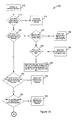
- Figs. 1A and 1B illustrate a control flow for an exemplary service diagnostic trouble code sequencing method implemented into an exemplary service DTC sequencer 100.
- the service DTC sequencer 100 starts by retrieving the active and previously active DTCs from the ECU or other memory device holding the DTCs.
- the service DTC sequencer 100 checks whether any of the active DTCs indicate abnormal battery voltage. If any of the active DTCs indicate abnormal battery voltage then at block 112, the service DTC sequencer 100 recommends diagnosing these abnormal battery voltage DTCs first. Otherwise, the service DTC sequencer 100 proceeds to block 120.
- the service DTC sequencer 100 checks whether any of the active DTCs indicate detection of an out-of-range condition. If none of the active DTCs indicate detection of an out-of-range condition, the service DTC sequencer 100 proceeds to block 140. If any of the active DTCs indicate detection of an out-of-range condition, then at block 122 the service DTC sequencer 100 checks if any of these out-of-range condition DTCs are for a sensor voltage supply. If any of these out-of-range condition DTCs are for a sensor voltage supply then at block 124, the service DTC sequencer 100 recommends diagnosing the out-of-range condition DTCs for the sensor supply voltage first.
- the service DTC sequencer 100 checks if there is more than one DTC fitting this criteria. If there is more than one DTC then at block 128, the service DTC sequencer 100 recommends diagnosing these out-of-range DTCs first and if the applicable affected components have a common circuit then inspecting that common circuit first. If there is only one DTC, then at block 130, the service DTC sequencer 100 recommends diagnosing this out-of-range DTC first.
- the technician can use schematics, manuals or other source to determine if multiple affected components have a common circuit.
- the service DTC sequencer 100 could include a database indicating component relationships and flow, and it could use this database to provide a recommendation to the technician on where to start diagnosis when there are more than one out-of-range DTCs.
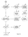
- the service DTC sequencer 100 checks whether any of the previously active DTCs indicate abnormal battery voltage or out-of-range conditions. If any of the previously active DTCs indicate abnormal battery voltage or out-of-range conditions then at block 142, the service DTC sequencer 100 recommends diagnosing these previously active DTCs first. Otherwise, the service DTC sequencer 100 proceeds to block 150.
- the service DTC sequencer 100 checks whether any of the active DTCs indicate an engine position measurement problem. If any of the active DTCs indicate an engine position measurement problem then at block 152, the service DTC sequencer 100 recommends diagnosing these engine position DTCs first. Otherwise, the service DTC sequencer 100 proceeds to block 160.
- the service DTC sequencer 100 checks whether any DTCs indicate an in-range failure for a system measured by a real (physical) sensor. If none of the DTCs indicate an in-range failure for a system measured by a physical sensor, the service DTC sequencer 100 proceeds to block 170. If any of the DTCs indicate an in-range failure for a system measured by a physical sensor then at block 162, the service DTC sequencer 100 checks whether any of these physical sensor DTCs indicate abnormal engine coolant temperature. If any of these physical sensor DTCs indicate abnormal engine coolant temperature then at block 164, the service DTC sequencer 100 recommends diagnosing these DTCs first.
- the service DTC sequencer 100 prioritizes upstream failures before downstream failures and at block 168, the service DTC sequencer 100 recommends diagnosing upstream DTCs first.
- the low pressure fuel system supplies the high pressure fuel system, so block 166 would prioritize the upstream low pressure fuel system and block 168 would recommend diagnosing the upstream low pressure fuel system DTCs before any downstream high pressure fuel system DTCs.
- the service DTC sequencer can use a common or application specific database to determine upstream versus downstream relationships for system components.
- the service DTC sequencer 100 checks whether any DTCs indicate an in-range failure for a system measured by a virtual sensor.
- Virtual sensors are modeled values based upon a variety of real sensors, thus the virtual sensor DTCs are checked after it is confirmed that there are no real sensor DTCs. If any of these virtual sensor DTCs indicate an in-range failure for a system measured by a virtual sensor then at block 172, the service DTC sequencer 100 prioritizes upstream failures before downstream failures and at block 174, the service DTC sequencer 100 recommends diagnosing upstream virtual sensor DTCs first.
- the service DTC sequencer 100 checks whether there are any active DTCs remaining. If there are any active DTCs remaining then at block 182, the service DTC sequencer 100 recommends diagnosing the remaining active DTCs first. Otherwise at block 184, where there are no active DTCs remaining, the service DTC sequencer 100 makes no recommendation.
- the service DTC sequencer 100 returns a category with one or more DTCs to diagnose first based on the ending block of the branch where processing ends.
- the ending blocks include block 112 which returns a category of abnormal battery voltage DTCs, block 124 which returns a category of active out-of-range DTCs for the sensor supply voltage, blocks 128 and 130 which return a category of other active out-of-range DTCs, block 142 which returns a category of previously active abnormal battery voltage or out-of-range DTCs, block 152 which returns a category of engine position DTCs, block 164 which returns a category of abnormal engine coolant temperature DTCs, block 168 which returns a category of other real sensor DTCs, block 174 which returns a category of virtual sensor DTCs, and block 182 which returns a category of remaining active DTCs.
- some of the blocks for example blocks 128, 168 and 174, return a prioritized list of DTCs within the category.
- the service DTC sequencer 100 returns a prioritized list of the multiple input DTCs broken down into the above categories. This can be done by simply reconnecting each branch ending block back with the main control flow. For example, connecting control flow from block 112 to block 120; from blocks 124, 128 and 130 to block 140; from block 142 to block 150; from block 152 to block 160; from blocks 164 and 168 to block 170; and from block 174 to block 180.
- the recommendation would be to diagnose the DTCs starting in the first category and working down through the categories.
- FIG. 2 illustrates various alternative example environments in which a service DTC sequencer could operate.
- a machine 200 can be connected, wired or wirelessly, to an electronic device, for example a computer 210 or a tablet 230.
- the service DTC sequencer can run as part of an electronic service tool in the repair facility on the electronic device, computer 210 or tablet 230.
- a service technician in the field can connect a service tool, for example the tablet 230, to gather the current DTC information from the machine 200 and upload this information over a network 250 to a service DTC sequencer on a remotely connected computer 260.
- the service DTC sequencer can determine which DTC(s) to diagnose first and download the resulting recommendation from the computer 260 to the tablet 230 in the field through the network 250.
- the network 250 can be the Internet, a wide area network, local area network or any other type of network enabling electronic devices to exchange information.
- an on-board telematics device on the machine 200 can monitor DTC status, send the DTC information over the network 250 to a remote system 260 to process the DTC information and derive a diagnostic sequence.
- the remote system 260 can provide the diagnostic sequence recommendation to a service technician locally on an electronic device 270 or remotely to a remote electronic device 272.
- the system to process the DTC information and derive the diagnostic sequence could be on the machine 200 (for example, in the ECU) and the machine resident system could provide the diagnostic sequence recommendation to a local or remote service technician through, for example, the electronic device 210, 230 or 272.
- the service DTC sequencer could provide the service technician with a recommendation on which DTC to diagnose first prior to departing to the field, which would enable the technician to bring any parts along on the service call which are necessary to complete the repair, further decreasing diagnostic time and costs.
- Any application-specific or common databases used by the service DTC sequencer can be locally or remotely accessible by the service DTC sequencer.
- a service DTC sequencer can substantially reduce costs and increase customer machine uptime by quickly directing a service technician to the root cause of a problem.
- a service DTC sequencer is not limited to use with an engine but could be applied to other components or a system of components.
- a service DTC sequencer can be used with an entire vehicle where there are multiple electronic controllers for various subsystems (for example, engines, transmissions, etc.) which set independent DTCs.
- a root cause failure or DTC in one controller e.g., transmission controller
- the service DTC sequencer can provide recommendations on which DTC to diagnose first from a plurality of controllers which may each have multiple DTCs.
Landscapes
- Engineering & Computer Science (AREA)
- Theoretical Computer Science (AREA)
- General Physics & Mathematics (AREA)
- Physics & Mathematics (AREA)
- Quality & Reliability (AREA)
- General Engineering & Computer Science (AREA)
- Biomedical Technology (AREA)
- Health & Medical Sciences (AREA)
- Automation & Control Theory (AREA)
- Business, Economics & Management (AREA)
- Human Computer Interaction (AREA)
- Testing And Monitoring For Control Systems (AREA)
- Databases & Information Systems (AREA)
- Human Resources & Organizations (AREA)
- General Business, Economics & Management (AREA)
- Economics (AREA)
- Entrepreneurship & Innovation (AREA)
- Computational Linguistics (AREA)
- Operations Research (AREA)
- Data Mining & Analysis (AREA)
- Marketing (AREA)
- Tourism & Hospitality (AREA)
- Strategic Management (AREA)
Abstract
Description
- The present invention relates to a service diagnostic trouble code sequencing method.
- Complex systems such as an electronically controlled diesel engine typically utilize diagnostic trouble codes (DTCs), failure mode indicators (FMIs), suspect parameter numbers (SPNs), and/or other notifications to assist a service technician in diagnosing a problem with the system. DTCs will be used generally to encompass these various notifications, including for example failure, fault and/or error codes. One failure mode will often result in multiple DTCs. For example, a problem with a regulated sensor voltage supply shared by several sensors may result in a voltage out of range DTC for each sensor as well as a DTC indicating a problem with the regulated voltage supply. The sensor voltage out of range DTCs are symptoms of the root cause which is a problem with the regulated voltage supply. The service technician makes the decision on which DTC to diagnose first when there are multiple DTCs present. If the technician begins diagnosing the system by troubleshooting one of the symptom DTCs instead of the root cause DTC, the time and effort, and possibly cost, required to diagnose the system will be increased.
- In another example, modeled or virtual sensors typically use information from physical or real sensors to calculate virtual sensor data. A problem with a physical sensor which is used in the calculation of a virtual sensor can result in a DTC for the virtual sensor along with a DTC for the physical sensor. Without engineering-level information, the interaction between physical sensors and virtual sensors would likely not be evident to a service technician. Therefore, the technician may start diagnosing the DTC for the virtual sensor before diagnosing the root cause which is the DTC for the physical sensor.
- In addition to electrical issues, mechanical problems can result in multiple DTCs. For example, diesel engine fuel system pressure sensors are typically located in the low-pressure fuel supply system and the high-pressure (i.e., common rail) system. A re-stricted fuel filter can cause DTCs for both the low-pressure and high-pressure fuel systems. A DTC for the low-pressure fuel system could become active indicating a problem has been detected, and then at a later time the DTC for the high-pressure fuel system could become active. However, both DTCs for the low-pressure and high- pressure fuel systems could be active when the technician begins diagnosing the problems. An inexperienced technician may begin the diagnosis by troubleshooting the active high-pressure fuel system DTC and ignore the previously active low-pressure fuel system DTC, leading to needless replacement of expensive components.
- Some system manuals provide service diagnostic procedures with troubleshooting sequence lists for each DTC diagnostic procedure. This static list requires a technician to compare the list of DTCs to be diagnosed first with the current list of active or previously active DTCs on the machine. There is no recommendation in the service information providing the technician information on where to start when there are several DTCs present on the same machine.
- Some manufacturers have on-line tools that provide a technician with a recommendation for a multiple DTC diagnostic sequence. However, these tools require the technician to manually enter each DTC present on the machine into the on-line tool and do not appear to be application specific. Other systems provide a process of generating test sequences to diagnose a problem, but not a means of prioritizing which DTC to diagnose first.
- It would be desirable to have a method which processes multiple DTCs for an application and provides a prioritized and targeted list for a technician regarding which DTC is likely indicating the root cause problem for the application, thus reducing diagnostic time and cost.
- These and other objects are achieved by the present invention, wherein a service diagnostic trouble code sequencing method is disclosed. The service diagnostic trouble code sequencing method includes the steps of receiving a plurality of diagnostic trouble codes (DTCs); determining which of the plurality of DTCs to diagnose first; and recommending one or more of the plurality of DTCs to diagnose first.
- The determining step can include determining a first category of DTCs to diagnose, where the first category of DTCs to diagnose includes one or more DTCs; and the recommending step can include outputting the one or more DTCs in the first category of DTCs to diagnose. The determining step can also include prioritizing the one or more DTCs in the first category of DTCs to diagnose; and the recommending step can also include outputting a prioritized list of the one or more DTCs in the first category of DTCs to diagnose. When multiple DTCs in the first category of DTCs to diagnose are for a common path with flow from upstream to downstream, the determining step can include prioritizing the multiple DTCs from upstream failure DTCs to downstream failure DTCs.
- The determining step can include separating the plurality of DTCs into multiple categories of DTCs, and prioritizing the multiple categories of DTCs; and the recommending step can include outputting a prioritized list of the multiple categories of DTCs. The determining step can also include prioritizing the DTCs in an ordered category of the multiple categories of DTCs; and for the ordered category, the recommending step can include outputting the prioritized list of DTCs in the ordered category.
- The service diagnostic trouble code sequencing method can include the step of receiving the plurality of DTCs locally or remotely over a network. The service diagnostic trouble code sequencing method can include the step of outputting the one or more DTCs to diagnose first locally or remotely over a network. The service diagnostic trouble code sequencing method can include the steps of receiving the plurality of DTCs locally, and sending the one or more DTCs to diagnose first remotely over a network.
- The above and other features will become apparent from the following description and the attached drawings.
- For a complete understanding of the objects, techniques, and structure of the invention reference should be made to the following detailed description and accompanying drawings:
- Fig. 1a
- illustrates a first portion of a control flow for an exemplary service diagnostic trouble code sequencing method embodying the invention,
- Fig. 1B
- illustrates a second portion of the control flow for the exemplary service diagnostic trouble code sequencing method of
Fig. 1A , and - Fig. 2
- illustrates various alternative example environments in which a service DTC sequencer could operate.
- Complex systems such as an electronically controlled diesel engine can utilize diagnostic trouble codes (DTCs) as a means of assisting a service technician in diagnosing a problem. DTCs may also be called fault codes, error codes or other names. It is not uncommon for one failure mode to result in multiple DTCs indicating a root cause problem and one or more symptoms of the root cause problem. A service technician has to decide which DTC to diagnose first when there are multiple DTCs present. If the technician begins the diagnosis of the system by troubleshooting one of the symptom DTCs instead of the root cause DTC, the time and effort required to diagnose the system will be increased.
- A service DTC sequencer can help the service technician to determine which DTC to diagnose first when there are multiple DTCs present. The service DTC sequencer is an interactive service tool and/or process that provides a recommendation to a service technician regarding which DTC to diagnose first when multiple active or previously active DTCs have been logged by an electronic control unit (ECU) or other system. The recommendation can be based on an algorithm that uses a set of fundamental rules; but the logic can be tailored to a specific application to obtain more accurate results. The invention can obtain current DTC status using industry standard methods (e.g., SAE J1939-73, ISO 15765-3) and use this information to return the recommended DTC troubleshooting sequence to reduce diagnostic time and effort. Society of Automotive Engineers (SAE) recommended practice J1939-73 defines a DTC as a suspect parameter number (SPN) and failure mode indicator (FMI). The service DTC sequencer can use the SAE J1939 defined FMI as a means of prioritization, or the equivalent for other applications. The SAE J1939 SPN can also be used to prioritize specific systems such as primary battery voltage or those SPNs describing a sensor regulated voltage supply.
- For example, at run time, the system can query the ECU regarding DTC active and previously active fault status which can include, for example, SAE J1939-73 DM1, DM2, DM4 or ISO 15765 equivalents. The system can pass the DTC information through a series of steps designed to determine which DTC(s) is likely indicating the root cause of the problem. The system can then provide a recommendation to the technician on which DTC(s) to diagnose first.
- The system can be customized or tailored for a specific application. For example, a first engine type may use a common return (ground) circuit for a number of sensors. A failure in the common return circuit may result in voltage out of range DTCs for all applicable sensors. In another engine type, the sensors which use a common return circuit may be different. An external information file unique to the application (engine type in this case) can be utilized at run time based on specific application identification (e.g. engine model number) to provide the technician with a recommendation specific to that application. Additionally, this external file can be updated to permit known issues which are found to result in a combination of seemingly unrelated DTCs to be prioritized according to the learning update.
-
Figs. 1A and1B illustrate a control flow for an exemplary service diagnostic trouble code sequencing method implemented into an exemplaryservice DTC sequencer 100. - At
block 102, theservice DTC sequencer 100 starts by retrieving the active and previously active DTCs from the ECU or other memory device holding the DTCs. - At
block 110, theservice DTC sequencer 100 checks whether any of the active DTCs indicate abnormal battery voltage. If any of the active DTCs indicate abnormal battery voltage then atblock 112, theservice DTC sequencer 100 recommends diagnosing these abnormal battery voltage DTCs first. Otherwise, theservice DTC sequencer 100 proceeds to block 120. - At
block 120, theservice DTC sequencer 100 checks whether any of the active DTCs indicate detection of an out-of-range condition. If none of the active DTCs indicate detection of an out-of-range condition, theservice DTC sequencer 100 proceeds to block 140. If any of the active DTCs indicate detection of an out-of-range condition, then atblock 122 theservice DTC sequencer 100 checks if any of these out-of-range condition DTCs are for a sensor voltage supply. If any of these out-of-range condition DTCs are for a sensor voltage supply then atblock 124, theservice DTC sequencer 100 recommends diagnosing the out-of-range condition DTCs for the sensor supply voltage first. Atblock 126, where at least one active DTC indicates detection of an out-of-range condition and no DTC is for a sensor voltage supply, theservice DTC sequencer 100 checks if there is more than one DTC fitting this criteria. If there is more than one DTC then atblock 128, theservice DTC sequencer 100 recommends diagnosing these out-of-range DTCs first and if the applicable affected components have a common circuit then inspecting that common circuit first. If there is only one DTC, then atblock 130, theservice DTC sequencer 100 recommends diagnosing this out-of-range DTC first. The technician can use schematics, manuals or other source to determine if multiple affected components have a common circuit. Alternatively, theservice DTC sequencer 100 could include a database indicating component relationships and flow, and it could use this database to provide a recommendation to the technician on where to start diagnosis when there are more than one out-of-range DTCs. - At
block 140, theservice DTC sequencer 100 checks whether any of the previously active DTCs indicate abnormal battery voltage or out-of-range conditions. If any of the previously active DTCs indicate abnormal battery voltage or out-of-range conditions then atblock 142, theservice DTC sequencer 100 recommends diagnosing these previously active DTCs first. Otherwise, theservice DTC sequencer 100 proceeds to block 150. - At
block 150, theservice DTC sequencer 100 checks whether any of the active DTCs indicate an engine position measurement problem. If any of the active DTCs indicate an engine position measurement problem then atblock 152, theservice DTC sequencer 100 recommends diagnosing these engine position DTCs first. Otherwise, theservice DTC sequencer 100 proceeds to block 160. - At
block 160, theservice DTC sequencer 100 checks whether any DTCs indicate an in-range failure for a system measured by a real (physical) sensor. If none of the DTCs indicate an in-range failure for a system measured by a physical sensor, theservice DTC sequencer 100 proceeds to block 170. If any of the DTCs indicate an in-range failure for a system measured by a physical sensor then atblock 162, theservice DTC sequencer 100 checks whether any of these physical sensor DTCs indicate abnormal engine coolant temperature. If any of these physical sensor DTCs indicate abnormal engine coolant temperature then atblock 164, theservice DTC sequencer 100 recommends diagnosing these DTCs first. If none of these physical sensor DTCs indicate abnormal engine coolant temperature then atblock 166, theservice DTC sequencer 100 prioritizes upstream failures before downstream failures and atblock 168, theservice DTC sequencer 100 recommends diagnosing upstream DTCs first. For example, the low pressure fuel system supplies the high pressure fuel system, so block 166 would prioritize the upstream low pressure fuel system and block 168 would recommend diagnosing the upstream low pressure fuel system DTCs before any downstream high pressure fuel system DTCs. The service DTC sequencer can use a common or application specific database to determine upstream versus downstream relationships for system components. - At
block 170, theservice DTC sequencer 100 checks whether any DTCs indicate an in-range failure for a system measured by a virtual sensor. Virtual sensors are modeled values based upon a variety of real sensors, thus the virtual sensor DTCs are checked after it is confirmed that there are no real sensor DTCs. If any of these virtual sensor DTCs indicate an in-range failure for a system measured by a virtual sensor then atblock 172, theservice DTC sequencer 100 prioritizes upstream failures before downstream failures and atblock 174, theservice DTC sequencer 100 recommends diagnosing upstream virtual sensor DTCs first. - At
block 180, theservice DTC sequencer 100 checks whether there are any active DTCs remaining. If there are any active DTCs remaining then atblock 182, theservice DTC sequencer 100 recommends diagnosing the remaining active DTCs first. Otherwise atblock 184, where there are no active DTCs remaining, theservice DTC sequencer 100 makes no recommendation. - In the embodiment illustrated in
Figs. 1A and1B , theservice DTC sequencer 100 returns a category with one or more DTCs to diagnose first based on the ending block of the branch where processing ends. The ending blocks include block 112 which returns a category of abnormal battery voltage DTCs, block 124 which returns a category of active out-of-range DTCs for the sensor supply voltage, blocks 128 and 130 which return a category of other active out-of-range DTCs, block 142 which returns a category of previously active abnormal battery voltage or out-of-range DTCs, block 152 which returns a category of engine position DTCs, block 164 which returns a category of abnormal engine coolant temperature DTCs, block 168 which returns a category of other real sensor DTCs, block 174 which returns a category of virtual sensor DTCs, and block 182 which returns a category of remaining active DTCs. In addition, some of the blocks, for example blocks 128, 168 and 174, return a prioritized list of DTCs within the category. - In an alternative embodiment, the
service DTC sequencer 100 returns a prioritized list of the multiple input DTCs broken down into the above categories. This can be done by simply reconnecting each branch ending block back with the main control flow. For example, connecting control flow fromblock 112 to block 120; fromblocks block 142 to block 150; fromblock 152 to block 160; fromblocks block 174 to block 180. The recommendation would be to diagnose the DTCs starting in the first category and working down through the categories. -
Fig. 2 illustrates various alternative example environments in which a service DTC sequencer could operate. Amachine 200 can be connected, wired or wirelessly, to an electronic device, for example acomputer 210 or atablet 230. The service DTC sequencer can run as part of an electronic service tool in the repair facility on the electronic device,computer 210 ortablet 230. - In an alternative embodiment, a service technician in the field can connect a service tool, for example the
tablet 230, to gather the current DTC information from themachine 200 and upload this information over anetwork 250 to a service DTC sequencer on a remotely connectedcomputer 260. The service DTC sequencer can determine which DTC(s) to diagnose first and download the resulting recommendation from thecomputer 260 to thetablet 230 in the field through thenetwork 250. Thenetwork 250 can be the Internet, a wide area network, local area network or any other type of network enabling electronic devices to exchange information. - In another embodiment, an on-board telematics device on the
machine 200 can monitor DTC status, send the DTC information over thenetwork 250 to aremote system 260 to process the DTC information and derive a diagnostic sequence. Theremote system 260 can provide the diagnostic sequence recommendation to a service technician locally on anelectronic device 270 or remotely to a remoteelectronic device 272. Alternatively, the system to process the DTC information and derive the diagnostic sequence could be on the machine 200 (for example, in the ECU) and the machine resident system could provide the diagnostic sequence recommendation to a local or remote service technician through, for example, theelectronic device - Any application-specific or common databases used by the service DTC sequencer can be locally or remotely accessible by the service DTC sequencer.
- A service DTC sequencer can substantially reduce costs and increase customer machine uptime by quickly directing a service technician to the root cause of a problem. A service DTC sequencer is not limited to use with an engine but could be applied to other components or a system of components. For example, a service DTC sequencer can be used with an entire vehicle where there are multiple electronic controllers for various subsystems (for example, engines, transmissions, etc.) which set independent DTCs. In some instances, a root cause failure or DTC in one controller (e.g., transmission controller) can cause one or more DTCs not only in that controller, but in other controllers which control other systems (e.g., engine controller). The service DTC sequencer can provide recommendations on which DTC to diagnose first from a plurality of controllers which may each have multiple DTCs.
Claims (10)
- A service diagnostic trouble code sequencing method, the method comprises the steps of receiving a plurality of diagnostic trouble codes; determining which of the plurality of diagnostic trouble codes to diagnose first; and recommending one or more of the plurality of diagnostic trouble codes to diagnose first.
- The service diagnostic trouble code sequencing method according to claim 1, characterized in that the determining step comprises determining a first category of diagnostic trouble codes to diagnose, the first category of diagnostic trouble codes to diagnose comprising one or more diagnostic trouble codes; and the recommending step comprises outputting the one or more diagnostic trouble codes in the first category of diagnostic trouble codes to diagnose.
- The service diagnostic trouble code sequencing method according to claim 2, characterized in that the determining step further comprises prioritizing the one or more diagnostic trouble codes in the first category of diagnostic trouble codes to diagnose; and the recommending step further comprises outputting a prioritized list of the one or more diagnostic trouble codes in the first category of diagnostic trouble codes to diagnose.
- The service diagnostic trouble code sequencing method according to claim 3, characterized in that, when multiple diagnostic trouble codes of the one or more diagnostic trouble codes in the first category of diagnostic trouble codes to diagnose are for a common path with flow from upstream to downstream, the determining step further comprises prioritizing the multiple diagnostic trouble codes from upstream failure diagnostic trouble codes to downstream failure diagnostic trouble codes.
- The service diagnostic trouble code sequencing method according to at least one of claims 1 to 4, characterized in that the determining step comprises separating the plurality of diagnostic trouble codes into multiple categories of diagnostic trouble codes, and prioritizing the multiple categories of diagnostic trouble codes; and the recommending step comprises outputting a prioritized list of the multiple categories of diagnostic trouble codes.
- The service diagnostic trouble code sequencing method of claim 5, characterized in that the determining step further comprises prioritizing the diagnostic trouble codes in an ordered category of the multiple categories of diagnostic trouble codes; and the recommending step further comprises, for the ordered category, outputting the prioritized list of diagnostic trouble codes in the ordered category.
- The service diagnostic trouble code sequencing method according to at least one of claims 1 to 6, characterized by further comprising the step of receiving the plurality of diagnostic trouble codes remotely over a network.
- The service diagnostic trouble code sequencing method according to at least one of claims 1 to 7, characterized by further comprising the step of outputting the one or more of the plurality of diagnostic trouble codes to diagnose first remotely over a network.
- The service diagnostic trouble code sequencing method according to at least one of claims 1 to 8, characterized by further comprising the step of receiving the plurality of diagnostic trouble codes locally, and sending the one or more of the plurality of diagnostic trouble codes to diagnose first remotely over a network.
- A service diagnostic code sequencer for performing the service diagnostic trouble code sequencing method according to at least one of claims 1 to 9.
Applications Claiming Priority (1)
| Application Number | Priority Date | Filing Date | Title |
|---|---|---|---|
| US14/593,400 US9563492B2 (en) | 2015-01-09 | 2015-01-09 | Service diagnostic trouble code sequencer and method |
Publications (1)
| Publication Number | Publication Date |
|---|---|
| EP3043263A1 true EP3043263A1 (en) | 2016-07-13 |
Family
ID=55077349
Family Applications (1)
| Application Number | Title | Priority Date | Filing Date |
|---|---|---|---|
| EP15200084.0A Withdrawn EP3043263A1 (en) | 2015-01-09 | 2015-12-15 | Service diagnostic trouble code sequencing method |
Country Status (3)
| Country | Link |
|---|---|
| US (1) | US9563492B2 (en) |
| EP (1) | EP3043263A1 (en) |
| CN (1) | CN105787565A (en) |
Cited By (2)
| Publication number | Priority date | Publication date | Assignee | Title |
|---|---|---|---|---|
| CN112596999A (en) * | 2020-12-08 | 2021-04-02 | 航天科技控股集团股份有限公司 | Diagnostic fault testing method for automobile instrument |
| EP3722901A4 (en) * | 2017-12-08 | 2021-09-01 | Autel Intelligent Technology Corp. Ltd. | VEHICLE FAULT DIAGNOSIS METHOD, VEHICLE FAULT DIAGNOSIS APPARATUS AND ELECTRONIC DEVICE |
Families Citing this family (70)
| Publication number | Priority date | Publication date | Assignee | Title |
|---|---|---|---|---|
| US20170024943A1 (en) | 2014-03-19 | 2017-01-26 | Cummins, Inc. | System and Method for Service Assessment |
| US10325037B2 (en) * | 2016-04-28 | 2019-06-18 | Caterpillar Inc. | System and method for analyzing operation of component of machine |
| US10943283B2 (en) | 2016-11-18 | 2021-03-09 | Cummins Inc. | Service location recommendation tailoring |
| US10217066B1 (en) | 2017-08-28 | 2019-02-26 | Deere & Company | Methods and apparatus to monitor work vehicles and to generate worklists to order the repair of such work vehicles should a machine failure be identified |
| CN107885191B (en) * | 2017-11-21 | 2020-10-20 | 山推工程机械股份有限公司 | Fault diagnosis method and device applied to engineering machinery vehicle body |
| US20200043249A1 (en) * | 2018-07-31 | 2020-02-06 | Robert Bosch Gmbh | System and Method for Incentivized Vehicle Diagnostics |
| US11653588B2 (en) | 2018-10-26 | 2023-05-23 | Deere & Company | Yield map generation and control system |
| US11240961B2 (en) | 2018-10-26 | 2022-02-08 | Deere & Company | Controlling a harvesting machine based on a geo-spatial representation indicating where the harvesting machine is likely to reach capacity |
| US11079725B2 (en) | 2019-04-10 | 2021-08-03 | Deere & Company | Machine control using real-time model |
| US11589509B2 (en) | 2018-10-26 | 2023-02-28 | Deere & Company | Predictive machine characteristic map generation and control system |
| US12069978B2 (en) | 2018-10-26 | 2024-08-27 | Deere & Company | Predictive environmental characteristic map generation and control system |
| US11672203B2 (en) | 2018-10-26 | 2023-06-13 | Deere & Company | Predictive map generation and control |
| US11178818B2 (en) | 2018-10-26 | 2021-11-23 | Deere & Company | Harvesting machine control system with fill level processing based on yield data |
| US11641800B2 (en) | 2020-02-06 | 2023-05-09 | Deere & Company | Agricultural harvesting machine with pre-emergence weed detection and mitigation system |
| US11467605B2 (en) | 2019-04-10 | 2022-10-11 | Deere & Company | Zonal machine control |
| US11957072B2 (en) | 2020-02-06 | 2024-04-16 | Deere & Company | Pre-emergence weed detection and mitigation system |
| US11234366B2 (en) | 2019-04-10 | 2022-02-01 | Deere & Company | Image selection for machine control |
| US11778945B2 (en) | 2019-04-10 | 2023-10-10 | Deere & Company | Machine control using real-time model |
| US12225846B2 (en) | 2020-02-06 | 2025-02-18 | Deere & Company | Machine control using a predictive map |
| US12035648B2 (en) | 2020-02-06 | 2024-07-16 | Deere & Company | Predictive weed map generation and control system |
| US12329148B2 (en) | 2020-02-06 | 2025-06-17 | Deere & Company | Predictive weed map and material application machine control |
| US12016257B2 (en) | 2020-02-19 | 2024-06-25 | Sabanto, Inc. | Methods for detecting and clearing debris from planter gauge wheels, closing wheels and seed tubes |
| US11477940B2 (en) | 2020-03-26 | 2022-10-25 | Deere & Company | Mobile work machine control based on zone parameter modification |
| US12461083B2 (en) | 2020-08-03 | 2025-11-04 | Sabanto, Inc. | Methods for improved agricultural procedures |
| US12422847B2 (en) | 2020-10-09 | 2025-09-23 | Deere & Company | Predictive agricultural model and map generation |
| US11871697B2 (en) | 2020-10-09 | 2024-01-16 | Deere & Company | Crop moisture map generation and control system |
| US12419220B2 (en) | 2020-10-09 | 2025-09-23 | Deere & Company | Predictive map generation and control system |
| US11635765B2 (en) | 2020-10-09 | 2023-04-25 | Deere & Company | Crop state map generation and control system |
| US11849672B2 (en) | 2020-10-09 | 2023-12-26 | Deere & Company | Machine control using a predictive map |
| US11592822B2 (en) | 2020-10-09 | 2023-02-28 | Deere & Company | Machine control using a predictive map |
| US11983009B2 (en) | 2020-10-09 | 2024-05-14 | Deere & Company | Map generation and control system |
| US11889788B2 (en) | 2020-10-09 | 2024-02-06 | Deere & Company | Predictive biomass map generation and control |
| US11849671B2 (en) | 2020-10-09 | 2023-12-26 | Deere & Company | Crop state map generation and control system |
| US12550802B2 (en) | 2020-10-08 | 2026-02-17 | Deere & Company | Predictive machine characteristic map generation and control system |
| US11844311B2 (en) | 2020-10-09 | 2023-12-19 | Deere & Company | Machine control using a predictive map |
| US11864483B2 (en) | 2020-10-09 | 2024-01-09 | Deere & Company | Predictive map generation and control system |
| US12013245B2 (en) | 2020-10-09 | 2024-06-18 | Deere & Company | Predictive map generation and control system |
| US11845449B2 (en) | 2020-10-09 | 2023-12-19 | Deere & Company | Map generation and control system |
| US12178158B2 (en) | 2020-10-09 | 2024-12-31 | Deere & Company | Predictive map generation and control system for an agricultural work machine |
| US11927459B2 (en) | 2020-10-09 | 2024-03-12 | Deere & Company | Machine control using a predictive map |
| US11711995B2 (en) | 2020-10-09 | 2023-08-01 | Deere & Company | Machine control using a predictive map |
| US11675354B2 (en) | 2020-10-09 | 2023-06-13 | Deere & Company | Machine control using a predictive map |
| US12386354B2 (en) | 2020-10-09 | 2025-08-12 | Deere & Company | Predictive power map generation and control system |
| US11946747B2 (en) | 2020-10-09 | 2024-04-02 | Deere & Company | Crop constituent map generation and control system |
| US11874669B2 (en) | 2020-10-09 | 2024-01-16 | Deere & Company | Map generation and control system |
| US11474523B2 (en) | 2020-10-09 | 2022-10-18 | Deere & Company | Machine control using a predictive speed map |
| US11650587B2 (en) | 2020-10-09 | 2023-05-16 | Deere & Company | Predictive power map generation and control system |
| US11727680B2 (en) | 2020-10-09 | 2023-08-15 | Deere & Company | Predictive map generation based on seeding characteristics and control |
| US11895948B2 (en) | 2020-10-09 | 2024-02-13 | Deere & Company | Predictive map generation and control based on soil properties |
| US12069986B2 (en) | 2020-10-09 | 2024-08-27 | Deere & Company | Map generation and control system |
| US11825768B2 (en) | 2020-10-09 | 2023-11-28 | Deere & Company | Machine control using a predictive map |
| US12250905B2 (en) | 2020-10-09 | 2025-03-18 | Deere & Company | Machine control using a predictive map |
| US11889787B2 (en) | 2020-10-09 | 2024-02-06 | Deere & Company | Predictive speed map generation and control system |
| US12127500B2 (en) | 2021-01-27 | 2024-10-29 | Deere & Company | Machine control using a map with regime zones |
| US12229886B2 (en) | 2021-10-01 | 2025-02-18 | Deere & Company | Historical crop state model, predictive crop state map generation and control system |
| US12310286B2 (en) | 2021-12-14 | 2025-05-27 | Deere & Company | Crop constituent sensing |
| US12302791B2 (en) | 2021-12-20 | 2025-05-20 | Deere & Company | Crop constituents, predictive mapping, and agricultural harvester control |
| US12245549B2 (en) | 2022-01-11 | 2025-03-11 | Deere & Company | Predictive response map generation and control system |
| US12143285B2 (en) | 2022-01-20 | 2024-11-12 | Deere & Company | Controller area network and connectivity health troubleshooting system |
| US12520759B2 (en) | 2022-01-26 | 2026-01-13 | Deere & Company | Systems and methods for predicting material dynamics |
| US12082531B2 (en) | 2022-01-26 | 2024-09-10 | Deere & Company | Systems and methods for predicting material dynamics |
| US12295288B2 (en) | 2022-04-05 | 2025-05-13 | Deere &Company | Predictive machine setting map generation and control system |
| US12358493B2 (en) | 2022-04-08 | 2025-07-15 | Deere & Company | Systems and methods for predictive power requirements and control |
| US12058951B2 (en) | 2022-04-08 | 2024-08-13 | Deere & Company | Predictive nutrient map and control |
| US12284934B2 (en) | 2022-04-08 | 2025-04-29 | Deere & Company | Systems and methods for predictive tractive characteristics and control |
| US12298767B2 (en) | 2022-04-08 | 2025-05-13 | Deere & Company | Predictive material consumption map and control |
| US12582035B2 (en) | 2022-04-08 | 2026-03-24 | Deere & Company | Systems and methods for predictive power requirements and control |
| US12192286B2 (en) | 2022-08-24 | 2025-01-07 | Deere & Company | Systems and methods for remote industrial machine communciation system diagnostics and solutions |
| CN119249133B (en) * | 2024-12-05 | 2025-03-14 | 武汉品致汽车技术有限公司 | Automobile DTC fault diagnosis flow development method |
| CN120560961B (en) * | 2025-07-31 | 2025-10-10 | 百思科新能源技术(青岛)有限公司 | Multi-fault parallel display method based on dynamic priority |
Citations (4)
| Publication number | Priority date | Publication date | Assignee | Title |
|---|---|---|---|---|
| US5491631A (en) * | 1991-12-25 | 1996-02-13 | Honda Giken Kogyo Kabushiki Kaisha | Fault diagnostic system for vehicles using identification and program codes |
| US20110224866A1 (en) * | 2010-03-10 | 2011-09-15 | Ieon Chen | Method and Apparatus for Indicating an Automotive Diagnostic Urgency |
| US20120259505A1 (en) * | 2011-04-06 | 2012-10-11 | Dassault Aviation | Method for analyzing faults present on a platform and associated system |
| US20140288761A1 (en) * | 2013-03-22 | 2014-09-25 | Bendix Commercial Vehicle Systems Llc | Enhanced display unit |
Family Cites Families (6)
| Publication number | Priority date | Publication date | Assignee | Title |
|---|---|---|---|---|
| US6574537B2 (en) | 2001-02-05 | 2003-06-03 | The Boeing Company | Diagnostic system and method |
| US7379846B1 (en) | 2004-06-29 | 2008-05-27 | Sun Microsystems, Inc. | System and method for automated problem diagnosis |
| US8428813B2 (en) | 2006-06-14 | 2013-04-23 | Service Solutions Us Llc | Dynamic decision sequencing method and apparatus for optimizing a diagnostic test plan |
| US9646432B2 (en) * | 2008-04-14 | 2017-05-09 | Innova Electronics Corporation | Hand held data retrieval device with fixed solution capability |
| US8498776B2 (en) | 2009-11-17 | 2013-07-30 | GM Global Technology Operations LLC | Fault diagnosis and prognosis using diagnostic trouble code markov chains |
| US20150073649A1 (en) * | 2013-09-11 | 2015-03-12 | General Motors Llc | Managing diagnostic trouble codes in a vehicle |
-
2015
- 2015-01-09 US US14/593,400 patent/US9563492B2/en active Active
- 2015-12-15 EP EP15200084.0A patent/EP3043263A1/en not_active Withdrawn
-
2016
- 2016-01-11 CN CN201610015156.6A patent/CN105787565A/en active Pending
Patent Citations (4)
| Publication number | Priority date | Publication date | Assignee | Title |
|---|---|---|---|---|
| US5491631A (en) * | 1991-12-25 | 1996-02-13 | Honda Giken Kogyo Kabushiki Kaisha | Fault diagnostic system for vehicles using identification and program codes |
| US20110224866A1 (en) * | 2010-03-10 | 2011-09-15 | Ieon Chen | Method and Apparatus for Indicating an Automotive Diagnostic Urgency |
| US20120259505A1 (en) * | 2011-04-06 | 2012-10-11 | Dassault Aviation | Method for analyzing faults present on a platform and associated system |
| US20140288761A1 (en) * | 2013-03-22 | 2014-09-25 | Bendix Commercial Vehicle Systems Llc | Enhanced display unit |
Cited By (2)
| Publication number | Priority date | Publication date | Assignee | Title |
|---|---|---|---|---|
| EP3722901A4 (en) * | 2017-12-08 | 2021-09-01 | Autel Intelligent Technology Corp. Ltd. | VEHICLE FAULT DIAGNOSIS METHOD, VEHICLE FAULT DIAGNOSIS APPARATUS AND ELECTRONIC DEVICE |
| CN112596999A (en) * | 2020-12-08 | 2021-04-02 | 航天科技控股集团股份有限公司 | Diagnostic fault testing method for automobile instrument |
Also Published As
| Publication number | Publication date |
|---|---|
| US9563492B2 (en) | 2017-02-07 |
| US20160203657A1 (en) | 2016-07-14 |
| CN105787565A (en) | 2016-07-20 |
Similar Documents
| Publication | Publication Date | Title |
|---|---|---|
| US9563492B2 (en) | Service diagnostic trouble code sequencer and method | |
| US8463485B2 (en) | Process for service diagnostic and service procedures enhancement | |
| EP2555114B1 (en) | Systems and methods for using a corrective action as diagnostic evidence | |
| US9836894B2 (en) | Distributed vehicle health management systems | |
| CN109001649B (en) | Intelligent power supply diagnosis system and protection method | |
| CN107918382B (en) | Automobile fault diagnosis method, automobile fault diagnosis device and electronic equipment | |
| JP4928532B2 (en) | Vehicle fault diagnosis device | |
| US10062219B2 (en) | Method for determining the cause of failure in a vehicle | |
| US5737215A (en) | Method and apparatus for comparing machines in fleet | |
| US8301333B2 (en) | Event-driven fault diagnosis framework for automotive systems | |
| EP2112492B1 (en) | Test requirement list for diagnostic tests | |
| JP4502037B2 (en) | Information generation apparatus and system for fault diagnosis | |
| EP2803048B1 (en) | System and method for providing diagnostic fault information | |
| US20190228322A1 (en) | Vehicle repair guidance system | |
| EP4167040A1 (en) | Fault model editor and diagnostic tool | |
| EP3523764A1 (en) | Methods and systems for updating diagnostic and repair information | |
| CN108563214A (en) | Vehicular diagnostic method, device and equipment | |
| CN112230621A (en) | Intelligent diagnosis system and method based on OBD | |
| CN108027611B (en) | Decision assistance system and method for machine maintenance utilizing decision-making pattern learning supervised by expert opinion | |
| US20180174373A1 (en) | Synthetic fault codes | |
| CN105469147B (en) | Method for diagnosing faults and/or diagnosing repair and/or maintenance needs | |
| US10102690B2 (en) | Non-starting engine remote diagnostic | |
| JP7026012B2 (en) | Equipment status monitoring system and equipment status monitoring method | |
| US20110144853A1 (en) | Mining methodology to eliminate inappropriate setting of error conditions using operating parameters | |
| CN116203916A (en) | Information processing apparatus and storage medium |
Legal Events
| Date | Code | Title | Description |
|---|---|---|---|
| PUAI | Public reference made under article 153(3) epc to a published international application that has entered the european phase |
Free format text: ORIGINAL CODE: 0009012 |
|
| AK | Designated contracting states |
Kind code of ref document: A1 Designated state(s): AL AT BE BG CH CY CZ DE DK EE ES FI FR GB GR HR HU IE IS IT LI LT LU LV MC MK MT NL NO PL PT RO RS SE SI SK SM TR |
|
| AX | Request for extension of the european patent |
Extension state: BA ME |
|
| 17P | Request for examination filed |
Effective date: 20170113 |
|
| RBV | Designated contracting states (corrected) |
Designated state(s): AL AT BE BG CH CY CZ DE DK EE ES FI FR GB GR HR HU IE IS IT LI LT LU LV MC MK MT NL NO PL PT RO RS SE SI SK SM TR |
|
| 17Q | First examination report despatched |
Effective date: 20190924 |
|
| STAA | Information on the status of an ep patent application or granted ep patent |
Free format text: STATUS: THE APPLICATION IS DEEMED TO BE WITHDRAWN |
|
| 18D | Application deemed to be withdrawn |
Effective date: 20200205 |