EP3043035A1 - A coupler for translating rotational forces - Google Patents
A coupler for translating rotational forces Download PDFInfo
- Publication number
- EP3043035A1 EP3043035A1 EP15199113.0A EP15199113A EP3043035A1 EP 3043035 A1 EP3043035 A1 EP 3043035A1 EP 15199113 A EP15199113 A EP 15199113A EP 3043035 A1 EP3043035 A1 EP 3043035A1
- Authority
- EP
- European Patent Office
- Prior art keywords
- rotational element
- plunger
- supply passage
- chamber
- Prior art date
- Legal status (The legal status is an assumption and is not a legal conclusion. Google has not performed a legal analysis and makes no representation as to the accuracy of the status listed.)
- Granted
Links
Images



Classifications
-
- F—MECHANICAL ENGINEERING; LIGHTING; HEATING; WEAPONS; BLASTING
- F16—ENGINEERING ELEMENTS AND UNITS; GENERAL MEASURES FOR PRODUCING AND MAINTAINING EFFECTIVE FUNCTIONING OF MACHINES OR INSTALLATIONS; THERMAL INSULATION IN GENERAL
- F16F—SPRINGS; SHOCK-ABSORBERS; MEANS FOR DAMPING VIBRATION
- F16F15/00—Suppression of vibrations in systems; Means or arrangements for avoiding or reducing out-of-balance forces, e.g. due to motion
- F16F15/10—Suppression of vibrations in rotating systems by making use of members moving with the system
- F16F15/16—Suppression of vibrations in rotating systems by making use of members moving with the system using a fluid or pasty material
- F16F15/161—Suppression of vibrations in rotating systems by making use of members moving with the system using a fluid or pasty material characterised by the fluid damping devices, e.g. passages, orifices
-
- F—MECHANICAL ENGINEERING; LIGHTING; HEATING; WEAPONS; BLASTING
- F01—MACHINES OR ENGINES IN GENERAL; ENGINE PLANTS IN GENERAL; STEAM ENGINES
- F01L—CYCLICALLY OPERATING VALVES FOR MACHINES OR ENGINES
- F01L1/00—Valve-gear or valve arrangements, e.g. lift-valve gear
- F01L1/02—Valve drive
- F01L1/026—Gear drive
-
- F—MECHANICAL ENGINEERING; LIGHTING; HEATING; WEAPONS; BLASTING
- F02—COMBUSTION ENGINES; HOT-GAS OR COMBUSTION-PRODUCT ENGINE PLANTS
- F02M—SUPPLYING COMBUSTION ENGINES IN GENERAL WITH COMBUSTIBLE MIXTURES OR CONSTITUENTS THEREOF
- F02M39/00—Arrangements of fuel-injection apparatus with respect to engines; Pump drives adapted to such arrangements
-
- F—MECHANICAL ENGINEERING; LIGHTING; HEATING; WEAPONS; BLASTING
- F16—ENGINEERING ELEMENTS AND UNITS; GENERAL MEASURES FOR PRODUCING AND MAINTAINING EFFECTIVE FUNCTIONING OF MACHINES OR INSTALLATIONS; THERMAL INSULATION IN GENERAL
- F16D—COUPLINGS FOR TRANSMITTING ROTATION; CLUTCHES; BRAKES
- F16D3/00—Yielding couplings, i.e. with means permitting movement between the connected parts during the drive
- F16D3/80—Yielding couplings, i.e. with means permitting movement between the connected parts during the drive in which a fluid is used
-
- F—MECHANICAL ENGINEERING; LIGHTING; HEATING; WEAPONS; BLASTING
- F16—ENGINEERING ELEMENTS AND UNITS; GENERAL MEASURES FOR PRODUCING AND MAINTAINING EFFECTIVE FUNCTIONING OF MACHINES OR INSTALLATIONS; THERMAL INSULATION IN GENERAL
- F16F—SPRINGS; SHOCK-ABSORBERS; MEANS FOR DAMPING VIBRATION
- F16F15/00—Suppression of vibrations in systems; Means or arrangements for avoiding or reducing out-of-balance forces, e.g. due to motion
- F16F15/10—Suppression of vibrations in rotating systems by making use of members moving with the system
- F16F15/12—Suppression of vibrations in rotating systems by making use of members moving with the system using elastic members or friction-damping members, e.g. between a rotating shaft and a gyratory mass mounted thereon
- F16F15/121—Suppression of vibrations in rotating systems by making use of members moving with the system using elastic members or friction-damping members, e.g. between a rotating shaft and a gyratory mass mounted thereon using springs as elastic members, e.g. metallic springs
-
- F—MECHANICAL ENGINEERING; LIGHTING; HEATING; WEAPONS; BLASTING
- F16—ENGINEERING ELEMENTS AND UNITS; GENERAL MEASURES FOR PRODUCING AND MAINTAINING EFFECTIVE FUNCTIONING OF MACHINES OR INSTALLATIONS; THERMAL INSULATION IN GENERAL
- F16F—SPRINGS; SHOCK-ABSORBERS; MEANS FOR DAMPING VIBRATION
- F16F15/00—Suppression of vibrations in systems; Means or arrangements for avoiding or reducing out-of-balance forces, e.g. due to motion
- F16F15/10—Suppression of vibrations in rotating systems by making use of members moving with the system
- F16F15/12—Suppression of vibrations in rotating systems by making use of members moving with the system using elastic members or friction-damping members, e.g. between a rotating shaft and a gyratory mass mounted thereon
- F16F15/121—Suppression of vibrations in rotating systems by making use of members moving with the system using elastic members or friction-damping members, e.g. between a rotating shaft and a gyratory mass mounted thereon using springs as elastic members, e.g. metallic springs
- F16F15/123—Wound springs
- F16F15/12353—Combinations of dampers, e.g. with multiple plates, multiple spring sets, i.e. complex configurations
-
- F—MECHANICAL ENGINEERING; LIGHTING; HEATING; WEAPONS; BLASTING
- F16—ENGINEERING ELEMENTS AND UNITS; GENERAL MEASURES FOR PRODUCING AND MAINTAINING EFFECTIVE FUNCTIONING OF MACHINES OR INSTALLATIONS; THERMAL INSULATION IN GENERAL
- F16H—GEARING
- F16H45/00—Combinations of fluid gearings for conveying rotary motion with couplings or clutches
- F16H45/02—Combinations of fluid gearings for conveying rotary motion with couplings or clutches with mechanical clutches for bridging a fluid gearing of the hydrokinetic type
-
- F—MECHANICAL ENGINEERING; LIGHTING; HEATING; WEAPONS; BLASTING
- F01—MACHINES OR ENGINES IN GENERAL; ENGINE PLANTS IN GENERAL; STEAM ENGINES
- F01L—CYCLICALLY OPERATING VALVES FOR MACHINES OR ENGINES
- F01L1/00—Valve-gear or valve arrangements, e.g. lift-valve gear
- F01L1/02—Valve drive
- F01L1/04—Valve drive by means of cams, camshafts, cam discs, eccentrics or the like
- F01L1/047—Camshafts
- F01L2001/054—Camshafts in cylinder block
-
- F—MECHANICAL ENGINEERING; LIGHTING; HEATING; WEAPONS; BLASTING
- F01—MACHINES OR ENGINES IN GENERAL; ENGINE PLANTS IN GENERAL; STEAM ENGINES
- F01L—CYCLICALLY OPERATING VALVES FOR MACHINES OR ENGINES
- F01L2810/00—Arrangements solving specific problems in relation with valve gears
- F01L2810/03—Reducing vibration
-
- F—MECHANICAL ENGINEERING; LIGHTING; HEATING; WEAPONS; BLASTING
- F02—COMBUSTION ENGINES; HOT-GAS OR COMBUSTION-PRODUCT ENGINE PLANTS
- F02B—INTERNAL-COMBUSTION PISTON ENGINES; COMBUSTION ENGINES IN GENERAL
- F02B75/00—Other engines
- F02B75/06—Engines with means for equalising torque
-
- F—MECHANICAL ENGINEERING; LIGHTING; HEATING; WEAPONS; BLASTING
- F02—COMBUSTION ENGINES; HOT-GAS OR COMBUSTION-PRODUCT ENGINE PLANTS
- F02M—SUPPLYING COMBUSTION ENGINES IN GENERAL WITH COMBUSTIBLE MIXTURES OR CONSTITUENTS THEREOF
- F02M2200/00—Details of fuel-injection apparatus, not otherwise provided for
- F02M2200/30—Fuel-injection apparatus having mechanical parts, the movement of which is damped
- F02M2200/306—Fuel-injection apparatus having mechanical parts, the movement of which is damped using mechanical means
Definitions
- the present disclosure relates to a coupler for rotating translating rotational forces.
- Tier 3 emissions regulations required an approximate 65 percent reduction in particulate matter ("PM") and a 60 percent reduction in nitrogen oxides ("NO x ”) from 1996 levels.
- Interim Tier 4 regulations required a 90 percent reduction in PM along with a 50 percent drop in NO x .
- Final Tier 4 regulations which will be fully implemented by 2015, will take PM and NO x emissions to near-zero levels.
- Manufacturers of maritime engines are also expected to meet emissions regulations though they vary from the nonroad emissions regulations (e.g., International Maritime Organization regulations).
- a coupler for translating a rotational force which includes a first rotational element and a second rotational element.
- the first element defines a first pocket.
- the second rotational element is in axial alignment therewith and defines a second pocket facing the first pocket.
- the first and second pockets define a dampening chamber therebetween that varies in volume based on an overlap thereof.
- a fluid is positioned in the dampening chamber, a portion of which is dispelled therefrom when the first rotational element rotates relative to the second rotational element and decreases the volume of the dampening chamber.
- the engine 106 may be an internal combustion engine, such as a gasoline engine, a diesel engine, a gaseous fuel burning engine (e.g., natural gas), or any other exhaust gas producing engine.
- a gasoline engine such as a gasoline engine, a diesel engine, a gaseous fuel burning engine (e.g., natural gas), or any other exhaust gas producing engine.
- a gaseous fuel burning engine e.g., natural gas
- the power system 100 comprises a coupler 119, and in the embodiment shown, the coupler 119 is mounted about a camshaft 114 and fixed for rotation therewith via a key 134 positioned in a key slot 135.
- the camshaft 114 may, for example, operate the valves through the mechanical linkage of pushrods and rocker arms.
- a timing gear cover 117 may be coupled to an end of the block 108, so as to surround the coupler 119 and keep it and the other components thereby clean and lubricated.
- the timing gear cover 117 may be two or more pieces.
- the timing gear cover 117 and the block 108 may sandwich a gasket 121.
- the coupler 119 includes a first rotational element 116 and a second rotational element 118 coupled to an in axial alignment with the first rotational element 116.
- the first rotational element 116 may include a hub 174, in which the second rotational element 118 is mounted about and rotatably coupled thereto.
- the second rotational element 118 is fully supported by the hub 174 and does not include its own bearing support (so as to reduce costs and complexity).
- Other embodiments, however, may include a bearing support between the first and second rotational elements 116, 118.
- the first and second rotational elements 116, 118 may be axially retained relative to one another via a snap ring 120 positioned in a snap ring groove 178. Further, an annular ring 122 may be sandwiched between a block 108 of the engine 106 and the snap ring 120.
- the block 108 is the main support for the other parts of the engine 106 and may be cast with end walls and center webs to support a crankshaft and the camshaft 114, and the block 108 may have enlargements in its walls for lubricant and coolant passages.
- the first rotational element 116 may be in mesh with and driven by a crankshaft gear 112.
- the second rotational element 118 may be in mesh with a fuel pump gear 126, which is used for driving a shaft 124 of a fuel pump 128.
- only one (or neither) of the rotational elements 116, 118 are gears.
- the fuel pump 128 may be a piston type high pressure pump and may provide fuel rail pressure of 250 MPa or more. Such pressures may impose a high cyclic torques on the engine drivetrain 107.
- the cyclic torque may be a result of a high torque value in one direction followed by a high torque in the opposite direction, even though the overall average torque is relatively low.
- This cyclic torque may be the result of the pistons injecting fluid into the cylinders of the engine 106.
- One potential technical effect of the coupler 119 is that it may dampen the high cycle torques, which may lower the noise levels and may prevent early failures of the engine drivetrain 107.
- the camshaft 114 may include a camshaft supply passage 158.
- the camshaft 114 may include an annular camshaft groove 157 positioned fluidly between the block supply passage 132 and the camshaft supply passage 158.
- Lubricant flowing through the block 108 may be supplied to the camshaft bearing 115 and flow into the camshaft supply passage 158 once per revolution of the camshaft 114, for instance when the camshaft supply passage 158 is in partial or full alignment with a block supply passage 132.
- the camshaft supply passage 158 may include a radial inlet passage 160, an offset axial passage 162, and a radial outlet passage 164.
- the offset axial passage 162 is positioned downstream of the radial inlet passage 160, and the radial outlet passage 164 is positioned downstream of the offset axial passage 162.
- An end of the offset axial passage 162 may be plugged with camshaft end plug 166.
- the camshaft end plug 166 may include a small aperture for providing fluid for lubricating the engine drivetrain 107.
- the coupler 119 translates a rotational force and comprises a first rotational element 116 and a second rotational element 118.
- the first rotational element 116 defines a first pocket 182, and the second rotational element 118-which is in rotational alignment therewith-defines a second pocket 184 facing the first pocket 182, both of which may be machined into place with a milling machine or cutter.
- the first and second pockets 182, 184 define a dampening chamber 186 therebetween that varies in volume based on the overlap thereof.
- a fluid is positioned in the dampening chamber 186. A portion of the fluid is dispelled therefrom when the first rotational element 116 rotates relative to the second rotational element 118, causing a decrease in the volume of the dampening chamber 186.
- the camshaft 114 may include a camshaft supply passage 158.
- the first rotational element 116 may include a first supply passage 179 positioned downstream of the camshaft supply passage 158, but upstream of the dampening chamber 186.
- An inlet 181 of the first supply passage 179 may be positioned at an inner circumferential surface 170 of the first rotational element 116, and an outlet 183 of the first supply passage 179 may be positioned at an outer circumferential surface 168 of the hub 174 of the first rotational element 116.
- the first rotational element 116 and the second rotational element 118 may cooperate, so as to define a second supply passage 185 positioned fluidly downstream of the first supply passage 179.
- An inlet 187 of the second supply passage 185 may be positioned at an inner circumferential surface 172 of the second rotational element 118, and an outlet 189 of the second supply passage 185 may open into the axial aperture 150.
- the second supply passage 185 is shown as having an L-shape, but could take various shapes and paths between the inlet 187 and the outlet 189.
- the coupler 119 may include a dampener 111 positioned in the dampening chamber 186, which may include a plunger receiver 131, a plunger 129 (positioned at least partially therein), and an elastic member 140.
- the dampener 111 is shown as being straight (about a single axis), but in other embodiments, the dampener 111 (and the components thereof) may be arced about an axis of the first and second rotational elements 116, 118.
- the first supply passage 179, the second supply passage 185, and the dampener 111 are shown in four locations spaced equidistantly about the axis of the first and second rotational elements 116, 118. The number and spacing of these components may vary, depending on coupler 119 and its application.
- the elastic member 140 may be positioned in the dampening chamber 186, so as to urge the pockets 182, 184 into rotational alignment with one another. But as the elastic member 140 is compressed a portion of the fluid is dispelled from the dampening chamber 186. The elastic member 140 and the dispelling of the fluid may absorb the fluctuating torque caused by the fuel pump 128 and dampen the torsional vibrations in the engine drivetrain 107.
- the first pocket 182 When the dampener 111 is in a fully extended position, the first pocket 182 may mirror and align with the second pocket 184. And when the dampener 111 is not in the fully extended position, the first pocket 182 may be offset from the second pocket 184.
- the plunger 129 may include a plunger cap 136 and a plunger cylinder 138 extending therefrom.
- An outer circumferential surface 141 of the plunger cap 136 may have a larger diameter than an outer circumferential surface 143 of the plunger cylinder 138.
- the outer circumferential surface 141 of the plunger cap 136 may contact and reciprocate on an inner circumferential surface 148 of the dampening chamber 186.
- the plunger receiver 131 may include a radially inward mating surface 154 that contacts the plunger cylinder 138, and the plunger 129 may reciprocate on the radially inward mating surface 154.
- the plunger cap 136 may include an axial aperture 150 that opens into the plunger cylinder 138, which may include a radial aperture 151 positioned fluidly between the axial aperture 150 and the dampening chamber 186. As illustrated, the radial aperture 151 may be one of a plurality of radial apertures 151.
- the plunger cap 136 and the plunger cylinder 138 may define a reversing flow chamber 161 positioned fluidly between the axial aperture 150 and the radial aperture 151.
- the plunger 129 may include a rapid flow base 146 on an opposite end of the plunger 129 relative to an end having the plunger cap 136.
- the plunger receiver 131 and the rapid flow base 146 define a plunging chamber 156 therebetween that varies in volume as the first rotational element 116 rotates relative to the second rotational element 118.
- An outer surface of the plunger 129 and an inner surface of the plunger receiver 131 may define an annular flow passage 190 positioned therebetween.
- the axial aperture 150 may be positioned fluidly between the second supply passage 185 and the reversing flow chamber 161.
- the reversing flow chamber 161 may be positioned fluidly between the axial aperture 150 and the radial aperture 151.
- the radial aperture 151 may be positioned fluidly between the reversing flow chamber 161 and the annular flow passage 190.
- the annular flow passage 190 may be positioned fluidly between the radial aperture 151 and the plunging chamber 156.
- the rapid flow base 146 may include a rapid flow check valve 159 positioned fluidly between the reversing flow chamber 161 and the plunging chamber 156.
- the rapid flow check valve 159 opens, in a first mode, so as to allow the fluid to flow from the reversing flow chamber 161 and quickly to the plunging chamber 156, but does not open so as to allow the fluid to flow from the plunging chamber 156 to the reversing flow chamber 161. Additionally, in the first mode, the fluid may enter the plunging chamber 156 by flowing through the axial aperture 150, the reversing chamber, the radial aperture 151, and then the annular flow passage 190.
- the rapid flow check valve 159 may include a flow controller 169, an elastic valve member 171, and a valve cage 173.
- the elastic valve member 171 may be sandwiched between the flow controller 169 and the valve cage 173.
- the valve cage 173 may be sandwiched between the flow controller 169 and the valve cage 173.
- the valve cage 173 may include an axial valve aperture 177 and a radial valve aperture 180.
- the radial valve aperture 180 may be one of a plurality of radial valve apertures 180.
- the valve cage 173 may be welded to the plunger cylinder 138 and is positioned fluidly between the reversing flow chamber 161 and the plunging chamber 156.
- the fluid may dispel from the plunging chamber 156 in a second mode by flowing through the annular flow passage 190, the radial aperture 151, the reversing chamber, and the axial aperture 150. This may occur when the first pocket 182 rotates relative to the second pocket 184, so as to decrease the volume of the dampening chamber 186 and the plunging chamber 156. Then, the fluid is dispelled from the axial aperture 150 through a radially outer annular passage 167, formed by an inner side 175 of the first rotational element 116 and an inner side 176 of the second rotational element 118. The fluid then may sling out onto other components of the engine drivetrain 107 and then recirculate back to the coupler 119 and other components of the engine 106.
Landscapes
- Engineering & Computer Science (AREA)
- General Engineering & Computer Science (AREA)
- Mechanical Engineering (AREA)
- Physics & Mathematics (AREA)
- Acoustics & Sound (AREA)
- Aviation & Aerospace Engineering (AREA)
- Chemical & Material Sciences (AREA)
- Combustion & Propulsion (AREA)
- Fuel-Injection Apparatus (AREA)
- Valve Device For Special Equipments (AREA)
- Rotary Pumps (AREA)
Abstract
Description
- The present disclosure relates to a coupler for rotating translating rotational forces.
- Manufacturers of nonroad diesel engines are expected to meet set emissions regulations. For example, Tier 3 emissions regulations required an approximate 65 percent reduction in particulate matter ("PM") and a 60 percent reduction in nitrogen oxides ("NOx") from 1996 levels. As a further example,
Interim Tier 4 regulations required a 90 percent reduction in PM along with a 50 percent drop in NOx. Still further,Final Tier 4 regulations, which will be fully implemented by 2015, will take PM and NOx emissions to near-zero levels. Manufacturers of maritime engines are also expected to meet emissions regulations though they vary from the nonroad emissions regulations (e.g., International Maritime Organization regulations). - One approach for potentially aiding in meeting emissions regulations is to increase the fuel rail pressure in the engine. Some pumps that operate at these increased pressures impose high cyclic torque loads on surrounding engine gear train components. High cyclic torque may cause an increase in gear noise and failures.
- Disclosed is a coupler for translating a rotational force, which includes a first rotational element and a second rotational element. The first element defines a first pocket. The second rotational element is in axial alignment therewith and defines a second pocket facing the first pocket. The first and second pockets define a dampening chamber therebetween that varies in volume based on an overlap thereof. A fluid is positioned in the dampening chamber, a portion of which is dispelled therefrom when the first rotational element rotates relative to the second rotational element and decreases the volume of the dampening chamber.
- The detailed description of the drawings refers to the accompanying figures in which:
-
FIG 1 . is a perspective view of an embodiment of a power system including a gear train, wherein the gear train includes a coupler; -
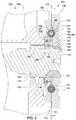
FIG. 2 is a sectional view taken along lines 2-2 ofFIG. 1 , showing a block of the power system and the coupler; -
FIG. 3 is an exploded perspective view of the coupler, illustrating a first rotational element and a second rotational element aligned axially therewith; -
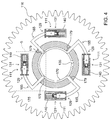
FIG. 4 is an elevational view taken along lines 4-4 ofFIG. 2 of the first rotational element, illustrating a plurality of dampeners; -
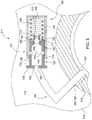
FIG. 5 is an enlarged elevational view ofportion 5 ofFIG. 4 , illustrating one of the plurality of the dampeners; -
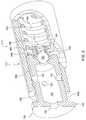
FIG. 6 is an enlarged perspective view of one of the plurality of dampeners, a portion of which is shown in cross section; and -
FIG. 7 is an elevational view of the second rotational element. - Like reference numerals in the various drawings indicate like elements.
- Referring to
FIGS. 1-2 , there is shown a schematic illustration of apower system 100 for providing power to a variety of machines, such as on-highway trucks, construction vehicles, marine vessels, stationary generators, automobiles, agricultural vehicles, and recreational vehicles. Theengine 106 may be an internal combustion engine, such as a gasoline engine, a diesel engine, a gaseous fuel burning engine (e.g., natural gas), or any other exhaust gas producing engine. - The
power system 100 comprises acoupler 119, and in the embodiment shown, thecoupler 119 is mounted about acamshaft 114 and fixed for rotation therewith via akey 134 positioned in akey slot 135. Thecamshaft 114 may, for example, operate the valves through the mechanical linkage of pushrods and rocker arms. - A
timing gear cover 117 may be coupled to an end of theblock 108, so as to surround thecoupler 119 and keep it and the other components thereby clean and lubricated. In some embodiments, thetiming gear cover 117 may be two or more pieces. Thetiming gear cover 117 and theblock 108 may sandwich agasket 121. - The
coupler 119 includes a firstrotational element 116 and a secondrotational element 118 coupled to an in axial alignment with the firstrotational element 116. As illustrated, the firstrotational element 116 may include ahub 174, in which the secondrotational element 118 is mounted about and rotatably coupled thereto. In the illustrated embodiment, the secondrotational element 118 is fully supported by thehub 174 and does not include its own bearing support (so as to reduce costs and complexity). Other embodiments, however, may include a bearing support between the first and secondrotational elements - The first and second
rotational elements snap ring 120 positioned in asnap ring groove 178. Further, anannular ring 122 may be sandwiched between ablock 108 of theengine 106 and thesnap ring 120. Theblock 108 is the main support for the other parts of theengine 106 and may be cast with end walls and center webs to support a crankshaft and thecamshaft 114, and theblock 108 may have enlargements in its walls for lubricant and coolant passages. - The first
rotational element 116 may be in mesh with and driven by acrankshaft gear 112. In contrast, the secondrotational element 118 may be in mesh with afuel pump gear 126, which is used for driving ashaft 124 of afuel pump 128. In other applications, only one (or neither) of therotational elements fuel pump 128 may be a piston type high pressure pump and may provide fuel rail pressure of 250 MPa or more. Such pressures may impose a high cyclic torques on theengine drivetrain 107. The cyclic torque may be a result of a high torque value in one direction followed by a high torque in the opposite direction, even though the overall average torque is relatively low. This cyclic torque may be the result of the pistons injecting fluid into the cylinders of theengine 106. One potential technical effect of thecoupler 119 is that it may dampen the high cycle torques, which may lower the noise levels and may prevent early failures of theengine drivetrain 107. - The camshaft 114 may include a
camshaft supply passage 158. Thecamshaft 114 may include anannular camshaft groove 157 positioned fluidly between theblock supply passage 132 and thecamshaft supply passage 158. Lubricant flowing through theblock 108 may be supplied to the camshaft bearing 115 and flow into thecamshaft supply passage 158 once per revolution of thecamshaft 114, for instance when thecamshaft supply passage 158 is in partial or full alignment with ablock supply passage 132. - The
camshaft supply passage 158 may include aradial inlet passage 160, an offsetaxial passage 162, and aradial outlet passage 164. The offsetaxial passage 162 is positioned downstream of theradial inlet passage 160, and theradial outlet passage 164 is positioned downstream of the offsetaxial passage 162. An end of the offsetaxial passage 162 may be plugged withcamshaft end plug 166. Thecamshaft end plug 166 may include a small aperture for providing fluid for lubricating theengine drivetrain 107. - Referring to
FIGS. 2-7 , thecoupler 119 translates a rotational force and comprises a firstrotational element 116 and a secondrotational element 118. The firstrotational element 116 defines afirst pocket 182, and the second rotational element 118-which is in rotational alignment therewith-defines asecond pocket 184 facing thefirst pocket 182, both of which may be machined into place with a milling machine or cutter. The first andsecond pockets dampening chamber 186 therebetween that varies in volume based on the overlap thereof. A fluid is positioned in thedampening chamber 186. A portion of the fluid is dispelled therefrom when the firstrotational element 116 rotates relative to the secondrotational element 118, causing a decrease in the volume of thedampening chamber 186. - The camshaft 114 may include a
camshaft supply passage 158. The firstrotational element 116 may include afirst supply passage 179 positioned downstream of thecamshaft supply passage 158, but upstream of thedampening chamber 186. Aninlet 181 of thefirst supply passage 179 may be positioned at an innercircumferential surface 170 of the firstrotational element 116, and an outlet 183 of thefirst supply passage 179 may be positioned at an outercircumferential surface 168 of thehub 174 of the firstrotational element 116. - The first
rotational element 116 and the secondrotational element 118 may cooperate, so as to define asecond supply passage 185 positioned fluidly downstream of thefirst supply passage 179. Aninlet 187 of thesecond supply passage 185 may be positioned at an innercircumferential surface 172 of the secondrotational element 118, and anoutlet 189 of thesecond supply passage 185 may open into theaxial aperture 150. Thesecond supply passage 185 is shown as having an L-shape, but could take various shapes and paths between theinlet 187 and theoutlet 189. - When the fluid dispels from the dampening
chamber 186, it flows through a radially outerannular passage 167 positioned between aninner side 175 of the firstrotational element 116 and aninner side 176 of the secondrotational element 118. - The
coupler 119 may include adampener 111 positioned in the dampeningchamber 186, which may include aplunger receiver 131, a plunger 129 (positioned at least partially therein), and anelastic member 140. In the illustrated embodiment, thedampener 111 is shown as being straight (about a single axis), but in other embodiments, the dampener 111 (and the components thereof) may be arced about an axis of the first and secondrotational elements first supply passage 179, thesecond supply passage 185, and thedampener 111 are shown in four locations spaced equidistantly about the axis of the first and secondrotational elements coupler 119 and its application. - As shown, the
elastic member 140 may be positioned in the dampeningchamber 186, so as to urge thepockets elastic member 140 is compressed a portion of the fluid is dispelled from the dampeningchamber 186. Theelastic member 140 and the dispelling of the fluid may absorb the fluctuating torque caused by thefuel pump 128 and dampen the torsional vibrations in theengine drivetrain 107. - When the
dampener 111 is in a fully extended position, thefirst pocket 182 may mirror and align with thesecond pocket 184. And when thedampener 111 is not in the fully extended position, thefirst pocket 182 may be offset from thesecond pocket 184. - The
plunger 129 may include aplunger cap 136 and aplunger cylinder 138 extending therefrom. An outer circumferential surface 141 of theplunger cap 136 may have a larger diameter than an outer circumferential surface 143 of theplunger cylinder 138. The outer circumferential surface 141 of theplunger cap 136 may contact and reciprocate on an innercircumferential surface 148 of the dampeningchamber 186. Theplunger receiver 131 may include a radiallyinward mating surface 154 that contacts theplunger cylinder 138, and theplunger 129 may reciprocate on the radiallyinward mating surface 154. Theplunger cap 136 may include anaxial aperture 150 that opens into theplunger cylinder 138, which may include aradial aperture 151 positioned fluidly between theaxial aperture 150 and the dampeningchamber 186. As illustrated, theradial aperture 151 may be one of a plurality ofradial apertures 151. Theplunger cap 136 and theplunger cylinder 138 may define a reversingflow chamber 161 positioned fluidly between theaxial aperture 150 and theradial aperture 151. - The
plunger 129 may include arapid flow base 146 on an opposite end of theplunger 129 relative to an end having theplunger cap 136. Theplunger receiver 131 and therapid flow base 146 define a plungingchamber 156 therebetween that varies in volume as the firstrotational element 116 rotates relative to the secondrotational element 118. - An outer surface of the
plunger 129 and an inner surface of theplunger receiver 131 may define anannular flow passage 190 positioned therebetween. Theaxial aperture 150 may be positioned fluidly between thesecond supply passage 185 and the reversingflow chamber 161. The reversingflow chamber 161 may be positioned fluidly between theaxial aperture 150 and theradial aperture 151. Theradial aperture 151 may be positioned fluidly between the reversingflow chamber 161 and theannular flow passage 190. Theannular flow passage 190 may be positioned fluidly between theradial aperture 151 and the plungingchamber 156. - The
rapid flow base 146 may include a rapidflow check valve 159 positioned fluidly between the reversingflow chamber 161 and the plungingchamber 156. The rapidflow check valve 159 opens, in a first mode, so as to allow the fluid to flow from the reversingflow chamber 161 and quickly to the plungingchamber 156, but does not open so as to allow the fluid to flow from the plungingchamber 156 to the reversingflow chamber 161. Additionally, in the first mode, the fluid may enter the plungingchamber 156 by flowing through theaxial aperture 150, the reversing chamber, theradial aperture 151, and then theannular flow passage 190. - The rapid
flow check valve 159 may include aflow controller 169, anelastic valve member 171, and avalve cage 173. Theelastic valve member 171 may be sandwiched between theflow controller 169 and thevalve cage 173. Thevalve cage 173 may be sandwiched between theflow controller 169 and thevalve cage 173. Further, thevalve cage 173 may include anaxial valve aperture 177 and aradial valve aperture 180. Theradial valve aperture 180 may be one of a plurality ofradial valve apertures 180. Thevalve cage 173 may be welded to theplunger cylinder 138 and is positioned fluidly between the reversingflow chamber 161 and the plungingchamber 156. - The fluid may dispel from the plunging
chamber 156 in a second mode by flowing through theannular flow passage 190, theradial aperture 151, the reversing chamber, and theaxial aperture 150. This may occur when thefirst pocket 182 rotates relative to thesecond pocket 184, so as to decrease the volume of the dampeningchamber 186 and the plungingchamber 156. Then, the fluid is dispelled from theaxial aperture 150 through a radially outerannular passage 167, formed by aninner side 175 of the firstrotational element 116 and aninner side 176 of the secondrotational element 118. The fluid then may sling out onto other components of theengine drivetrain 107 and then recirculate back to thecoupler 119 and other components of theengine 106. - While the disclosure has been illustrated and described in detail in the drawings and foregoing description, such illustration and description is to be considered as exemplary and not restrictive in character, it being understood that illustrative embodiments have been shown and described and that all changes and modifications that come within the spirit of the disclosure are desired to be protected. It will be noted that alternative embodiments of the present disclosure may not include all of the features described yet still benefit from at least some of the advantages of such features. Those of ordinary skill in the art may readily devise their own implementations that incorporate one or more of the features of the present disclosure and fall within the spirit and scope of the present invention as defined by the appended claims.
Claims (15)
- A coupler for translating a rotational force, comprising:a first rotational element defining a first pocket;a second rotational element in axial alignment with the first rotational element anddefining a second pocket facing the first pocket, the first pocket and the second pocket define a dampening chamber therebetween that varies in volume based on an overlap thereof; anda fluid positioned in the dampening chamber, a portion of the fluid being dispelled from the dampening chamber when the first rotational element rotates relative to the second rotational element and decreases the volume of the dampening chamber.
- The coupler according to claim 1, further comprising an elastic member positioned in the dampening chamber and configured to urge the first pocket and the second pocket to mirror and align with one another, the portion of the fluid being dispelled when the elastic member is compressed.
- The coupler according to claim 1 or 2, wherein the fluid dispels from the dampening chamber through an outer annular passage formed by an inner side of the first rotational element and an inner side of the second rotational element.
- The coupler according to any one of claims 1 to 3, wherein the first rotational element comprises a first supply passage positioned fluidly upstream of the dampening chamber, an inlet of the first supply passage is positioned at an inner circumferential surface of the first rotational element, and an outlet of the first supply passage is positioned at an outer circumferential surface of the first rotational element.
- The coupler according to any one of claims 1 to 4, further comprising a dampener positioned in the dampening chamber:a plunger receiver;a plunger positioned at least partially therein; andan elastic member, the plunger receiver being positioned in contact with an end of the elastic member, the portion of the fluid being dispelled when the elastic member is compressed.
- The coupler according to any one of claims 1 to 5, wherein the first pocket mirrors and aligns with the second pocket when the dampener is in a fully extended position, and the first pocket is offset from the second pocket when the dampener is not in the fully extended position.
- The couple according to any one of claims 5 to 6, wherein the plunger comprises a plunger cap and a plunger cylinder extending therefrom, an outer circumferential surface of the plunger cap has a larger diameter than an outer circumferential surface of the plunger cylinder, the outer circumferential surface of the plunger cap contacts and reciprocates on an inner circumferential surface of the dampening chamber.
- The coupler according to any one of claims 5 to 7, wherein the plunger receiver comprises a radially inward mating surface that contacts the plunger cylinder, and the plunger reciprocates on the radially inward mating surface.
- The coupler according to any one of claims 5 to 7, wherein the plunger comprises a plunger cap and a plunger cylinder extending therefrom, the plunger cap comprise an axial aperture that opens into the plunger cylinder, the plunger cylinder comprises a radial aperture positioned fluidly between the axial aperture and the dampening chamber.
- The coupler according to any one of claims 1 to 11, wherein:the first rotational element comprises a first supply passage positioned fluidly upstream of the dampening chamber, an inlet of the first supply passage is positioned at an inner circumferential surface of the first rotational element, and an outlet of the first supply passage is positioned at an outer circumferential surface of a hub of the first rotational element; andthe first rotational element and the second rotational element define a second supply passage positioned fluidly downstream of the first supply passage, an inlet of the second supply passage is positioned at an inner circumferential surface of the second rotational element, and an outlet of the second supply passage opens into the axial aperture.
- The coupler according to any one of claims 7 to 10, wherein the plunger cap and the plunger cylinder define a reversing flow chamber positioned fluidly between the axial aperture and the radial aperture.
- The coupler according to any one of claims 7 to 13, wherein the plunger comprises a rapid flow base on an opposite end of the plunger relative to an end having the plunger cap, the plunger receiver and the rapid flow base define a plunging chamber therebetween that varies in volume as the first rotational element rotates relative to the second rotational element.
- The coupler according to any one of claims 5 to 14, wherein an outer surface of the plunger and an inner surface of the plunger receiver define an annular flow passage positioned therebetween, the annular flow passage is positioned fluidly between the radial aperture and the plunging chamber, the fluid enters the plunging chamber in a first mode by flowing through the annular flow passage, and the fluid dispels from the plunging chamber in a second mode by flowing through the annular flow passage when the first pocket rotates relative to the second pocket and decreases the volume of the dampening chamber and the plunging chamber.
- An engine drivetrain, further comprising the coupler according to any one of claims 1 to 13, the engine drivetrain comprising a camshaft, the coupler mounted about the camshaft and fixed for rotation therewith, the first rotational element being in mesh with a crankshaft gear, and the second rotational element being in mesh with a fuel pump gear.
- The engine drivetrain of claim 14, wherein:the camshaft comprises a camshaft supply passage; andthe first rotational element comprises a first supply passage positioned downstream of the camshaft supply passage and positioned fluidly upstream of the dampening chamber, an inlet of the first supply passage is positioned at an inner circumferential surface of the first rotational element, and an outlet of the first supply passage is positioned at an outer circumferential surface of the first rotational element.
Applications Claiming Priority (1)
| Application Number | Priority Date | Filing Date | Title |
|---|---|---|---|
| US14/593,006 US9664251B2 (en) | 2015-01-09 | 2015-01-09 | Coupler for translating rotational forces |
Publications (2)
| Publication Number | Publication Date |
|---|---|
| EP3043035A1 true EP3043035A1 (en) | 2016-07-13 |
| EP3043035B1 EP3043035B1 (en) | 2018-06-06 |
Family
ID=55066298
Family Applications (1)
| Application Number | Title | Priority Date | Filing Date |
|---|---|---|---|
| EP15199113.0A Not-in-force EP3043035B1 (en) | 2015-01-09 | 2015-12-10 | A coupler for translating rotational forces |
Country Status (2)
| Country | Link |
|---|---|
| US (1) | US9664251B2 (en) |
| EP (1) | EP3043035B1 (en) |
Cited By (1)
| Publication number | Priority date | Publication date | Assignee | Title |
|---|---|---|---|---|
| WO2017137382A1 (en) * | 2016-02-12 | 2017-08-17 | Bayerische Motoren Werke Aktiengesellschaft | Device for reducing rotary vibrations in a drivetrain |
Families Citing this family (5)
| Publication number | Priority date | Publication date | Assignee | Title |
|---|---|---|---|---|
| KR101646120B1 (en) * | 2014-12-03 | 2016-08-05 | 현대자동차 주식회사 | Motor coupling device |
| US20190011013A1 (en) * | 2017-07-07 | 2019-01-10 | GM Global Technology Operations LLC | Active vibration damper for a vehicle driveline component |
| USD1076983S1 (en) * | 2020-06-29 | 2025-05-27 | Powerhouse Engine Solutions Switzerland IP Holding GmbH | Timing wheel |
| US11530733B2 (en) | 2020-11-03 | 2022-12-20 | Hamilton Sundstrand Corporation | Integrated hydraulic damper for torsional oscillation reduction |
| US12345309B1 (en) * | 2024-03-25 | 2025-07-01 | Ante Puljic | Gravitational torque amplifier apparatus and method |
Citations (4)
| Publication number | Priority date | Publication date | Assignee | Title |
|---|---|---|---|---|
| GB2170882A (en) * | 1985-01-23 | 1986-08-13 | Fichtel & Sachs Ag | Torsional vibration damper |
| DE19909914A1 (en) * | 1999-03-06 | 2000-09-28 | Mtu Friedrichshafen Gmbh | Hydraulic damper element esp. for engine bearing has spring columns formed by plate springs and spring bearings to form sealed volume within liquid-filled chamber |
| DE4345346C2 (en) * | 1992-10-30 | 2001-04-05 | Exedy Corp | Hydraulically damped clutch plate for vehicle |
| DE102012211526A1 (en) * | 2012-07-03 | 2014-01-09 | Schaeffler Technologies AG & Co. KG | Hydraulic camshaft adjusting device for internal combustion engine of motor vehicle e.g. passenger car, has wing arranged with hole or nozzle shaped co-ordinated attenuation throttle that is fluidly connected with pressure chambers parts |
Family Cites Families (8)
| Publication number | Priority date | Publication date | Assignee | Title |
|---|---|---|---|---|
| US1734043A (en) * | 1928-02-09 | 1929-11-05 | Carl E Nelson | Hydraulic flexible coupling |
| DE3639190A1 (en) * | 1986-11-15 | 1988-05-26 | Freudenberg Carl Fa | TURN VIBRATION DAMPER |
| SE464930B (en) * | 1989-09-20 | 1991-07-01 | Volvo Ab | FLY WHEELS FOR COMBUSTION ENGINES |
| JPH1182041A (en) | 1997-09-01 | 1999-03-26 | Suzuki Motor Corp | Power transmission device for internal combustion engine |
| KR100569389B1 (en) | 2003-10-07 | 2006-04-07 | 현대자동차주식회사 | Hydraulic Backlash Removal System of the Cam-to-Cam Drive System |
| DE102009045610A1 (en) * | 2009-10-13 | 2011-05-05 | Zf Friedrichshafen Ag | Wet-running clutch arrangement |
| TW201204964A (en) | 2010-07-23 | 2012-02-01 | Kwang Yang Motor Co | Backlash eliminator with lubricant |
| CN102072309A (en) | 2011-01-29 | 2011-05-25 | 重庆长安汽车股份有限公司 | Engine driven gear assembly with lubricating hole |
-
2015
- 2015-01-09 US US14/593,006 patent/US9664251B2/en not_active Expired - Fee Related
- 2015-12-10 EP EP15199113.0A patent/EP3043035B1/en not_active Not-in-force
Patent Citations (4)
| Publication number | Priority date | Publication date | Assignee | Title |
|---|---|---|---|---|
| GB2170882A (en) * | 1985-01-23 | 1986-08-13 | Fichtel & Sachs Ag | Torsional vibration damper |
| DE4345346C2 (en) * | 1992-10-30 | 2001-04-05 | Exedy Corp | Hydraulically damped clutch plate for vehicle |
| DE19909914A1 (en) * | 1999-03-06 | 2000-09-28 | Mtu Friedrichshafen Gmbh | Hydraulic damper element esp. for engine bearing has spring columns formed by plate springs and spring bearings to form sealed volume within liquid-filled chamber |
| DE102012211526A1 (en) * | 2012-07-03 | 2014-01-09 | Schaeffler Technologies AG & Co. KG | Hydraulic camshaft adjusting device for internal combustion engine of motor vehicle e.g. passenger car, has wing arranged with hole or nozzle shaped co-ordinated attenuation throttle that is fluidly connected with pressure chambers parts |
Cited By (2)
| Publication number | Priority date | Publication date | Assignee | Title |
|---|---|---|---|---|
| WO2017137382A1 (en) * | 2016-02-12 | 2017-08-17 | Bayerische Motoren Werke Aktiengesellschaft | Device for reducing rotary vibrations in a drivetrain |
| US10495179B2 (en) | 2016-02-12 | 2019-12-03 | Bayerische Motoren Werke Aktiengesellschaft | Device for reducing rotary vibrations in a drivetrain |
Also Published As
| Publication number | Publication date |
|---|---|
| US9664251B2 (en) | 2017-05-30 |
| US20160201758A1 (en) | 2016-07-14 |
| EP3043035B1 (en) | 2018-06-06 |
Similar Documents
| Publication | Publication Date | Title |
|---|---|---|
| EP3043035B1 (en) | A coupler for translating rotational forces | |
| US5154147A (en) | Rotary valve | |
| EP2816203B1 (en) | Camshaft phaser | |
| JPH1172014A (en) | Fuel pressurization pump | |
| JP2006153005A (en) | Eccentric crank variable compression ratio mechanism | |
| US10697413B2 (en) | Tappet assembly for use in a high-pressure fuel system of an internal combustion engine | |
| US10837416B2 (en) | Tappet assembly for use in a high-pressure fuel system of an internal combustion engine | |
| WO2012074610A1 (en) | Cam shaft/cam gear assembly and thrust strategy for engine using same | |
| CN105705746B (en) | Turbine recombiner unit | |
| JP5908364B2 (en) | Oil passage structure of internal combustion engine | |
| EP1767771A1 (en) | High-pressure fuel supply pump | |
| CA2542028C (en) | Internal combustion engine with torque converter | |
| US20110129359A1 (en) | Variable output pump | |
| WO2015163471A2 (en) | Engine | |
| US8813715B2 (en) | Vertical engine | |
| EA030441B1 (en) | Seal assembly for rotary piston internal combustion engine | |
| US9181909B2 (en) | Fuel pump retainer | |
| JP6115282B2 (en) | Camshaft lubrication device | |
| AU2021329294B2 (en) | Head assembly with rotary valves for an internal combustion engine | |
| EP3714176B1 (en) | Turbocharger for an internal combustion engine | |
| US8944022B2 (en) | Pump assembly for internal combustion engine | |
| JP4606386B2 (en) | Machine or internal combustion engine with rotation angle sensor | |
| JP2017206961A (en) | Lubricating oil supply device | |
| CN110778595B (en) | Crankshaft external full support structure | |
| JP2019132210A (en) | Lubricating oil supply structure |
Legal Events
| Date | Code | Title | Description |
|---|---|---|---|
| PUAI | Public reference made under article 153(3) epc to a published international application that has entered the european phase |
Free format text: ORIGINAL CODE: 0009012 |
|
| AK | Designated contracting states |
Kind code of ref document: A1 Designated state(s): AL AT BE BG CH CY CZ DE DK EE ES FI FR GB GR HR HU IE IS IT LI LT LU LV MC MK MT NL NO PL PT RO RS SE SI SK SM TR |
|
| AX | Request for extension of the european patent |
Extension state: BA ME |
|
| 17P | Request for examination filed |
Effective date: 20170113 |
|
| RBV | Designated contracting states (corrected) |
Designated state(s): AL AT BE BG CH CY CZ DE DK EE ES FI FR GB GR HR HU IE IS IT LI LT LU LV MC MK MT NL NO PL PT RO RS SE SI SK SM TR |
|
| 17Q | First examination report despatched |
Effective date: 20170406 |
|
| GRAP | Despatch of communication of intention to grant a patent |
Free format text: ORIGINAL CODE: EPIDOSNIGR1 |
|
| RIC1 | Information provided on ipc code assigned before grant |
Ipc: F16F 15/16 20060101ALI20171205BHEP Ipc: F01L 1/02 20060101AFI20171205BHEP Ipc: F16F 15/121 20060101ALI20171205BHEP Ipc: F16H 45/02 20060101ALI20171205BHEP Ipc: F02B 75/06 20060101ALN20171205BHEP |
|
| INTG | Intention to grant announced |
Effective date: 20180103 |
|
| GRAS | Grant fee paid |
Free format text: ORIGINAL CODE: EPIDOSNIGR3 |
|
| GRAA | (expected) grant |
Free format text: ORIGINAL CODE: 0009210 |
|
| AK | Designated contracting states |
Kind code of ref document: B1 Designated state(s): AL AT BE BG CH CY CZ DE DK EE ES FI FR GB GR HR HU IE IS IT LI LT LU LV MC MK MT NL NO PL PT RO RS SE SI SK SM TR |
|
| REG | Reference to a national code |
Ref country code: GB Ref legal event code: FG4D |
|
| REG | Reference to a national code |
Ref country code: CH Ref legal event code: EP Ref country code: AT Ref legal event code: REF Ref document number: 1006323 Country of ref document: AT Kind code of ref document: T Effective date: 20180615 |
|
| REG | Reference to a national code |
Ref country code: IE Ref legal event code: FG4D |
|
| REG | Reference to a national code |
Ref country code: DE Ref legal event code: R096 Ref document number: 602015011754 Country of ref document: DE |
|
| REG | Reference to a national code |
Ref country code: NL Ref legal event code: MP Effective date: 20180606 |
|
| REG | Reference to a national code |
Ref country code: LT Ref legal event code: MG4D |
|
| PG25 | Lapsed in a contracting state [announced via postgrant information from national office to epo] |
Ref country code: ES Free format text: LAPSE BECAUSE OF FAILURE TO SUBMIT A TRANSLATION OF THE DESCRIPTION OR TO PAY THE FEE WITHIN THE PRESCRIBED TIME-LIMIT Effective date: 20180606 Ref country code: SE Free format text: LAPSE BECAUSE OF FAILURE TO SUBMIT A TRANSLATION OF THE DESCRIPTION OR TO PAY THE FEE WITHIN THE PRESCRIBED TIME-LIMIT Effective date: 20180606 Ref country code: LT Free format text: LAPSE BECAUSE OF FAILURE TO SUBMIT A TRANSLATION OF THE DESCRIPTION OR TO PAY THE FEE WITHIN THE PRESCRIBED TIME-LIMIT Effective date: 20180606 Ref country code: BG Free format text: LAPSE BECAUSE OF FAILURE TO SUBMIT A TRANSLATION OF THE DESCRIPTION OR TO PAY THE FEE WITHIN THE PRESCRIBED TIME-LIMIT Effective date: 20180906 Ref country code: FI Free format text: LAPSE BECAUSE OF FAILURE TO SUBMIT A TRANSLATION OF THE DESCRIPTION OR TO PAY THE FEE WITHIN THE PRESCRIBED TIME-LIMIT Effective date: 20180606 Ref country code: NO Free format text: LAPSE BECAUSE OF FAILURE TO SUBMIT A TRANSLATION OF THE DESCRIPTION OR TO PAY THE FEE WITHIN THE PRESCRIBED TIME-LIMIT Effective date: 20180906 Ref country code: CY Free format text: LAPSE BECAUSE OF FAILURE TO SUBMIT A TRANSLATION OF THE DESCRIPTION OR TO PAY THE FEE WITHIN THE PRESCRIBED TIME-LIMIT Effective date: 20180606 |
|
| PG25 | Lapsed in a contracting state [announced via postgrant information from national office to epo] |
Ref country code: LV Free format text: LAPSE BECAUSE OF FAILURE TO SUBMIT A TRANSLATION OF THE DESCRIPTION OR TO PAY THE FEE WITHIN THE PRESCRIBED TIME-LIMIT Effective date: 20180606 Ref country code: RS Free format text: LAPSE BECAUSE OF FAILURE TO SUBMIT A TRANSLATION OF THE DESCRIPTION OR TO PAY THE FEE WITHIN THE PRESCRIBED TIME-LIMIT Effective date: 20180606 Ref country code: HR Free format text: LAPSE BECAUSE OF FAILURE TO SUBMIT A TRANSLATION OF THE DESCRIPTION OR TO PAY THE FEE WITHIN THE PRESCRIBED TIME-LIMIT Effective date: 20180606 Ref country code: GR Free format text: LAPSE BECAUSE OF FAILURE TO SUBMIT A TRANSLATION OF THE DESCRIPTION OR TO PAY THE FEE WITHIN THE PRESCRIBED TIME-LIMIT Effective date: 20180907 |
|
| REG | Reference to a national code |
Ref country code: AT Ref legal event code: MK05 Ref document number: 1006323 Country of ref document: AT Kind code of ref document: T Effective date: 20180606 |
|
| PG25 | Lapsed in a contracting state [announced via postgrant information from national office to epo] |
Ref country code: NL Free format text: LAPSE BECAUSE OF FAILURE TO SUBMIT A TRANSLATION OF THE DESCRIPTION OR TO PAY THE FEE WITHIN THE PRESCRIBED TIME-LIMIT Effective date: 20180606 |
|
| PG25 | Lapsed in a contracting state [announced via postgrant information from national office to epo] |
Ref country code: SK Free format text: LAPSE BECAUSE OF FAILURE TO SUBMIT A TRANSLATION OF THE DESCRIPTION OR TO PAY THE FEE WITHIN THE PRESCRIBED TIME-LIMIT Effective date: 20180606 Ref country code: EE Free format text: LAPSE BECAUSE OF FAILURE TO SUBMIT A TRANSLATION OF THE DESCRIPTION OR TO PAY THE FEE WITHIN THE PRESCRIBED TIME-LIMIT Effective date: 20180606 Ref country code: IS Free format text: LAPSE BECAUSE OF FAILURE TO SUBMIT A TRANSLATION OF THE DESCRIPTION OR TO PAY THE FEE WITHIN THE PRESCRIBED TIME-LIMIT Effective date: 20181006 Ref country code: PL Free format text: LAPSE BECAUSE OF FAILURE TO SUBMIT A TRANSLATION OF THE DESCRIPTION OR TO PAY THE FEE WITHIN THE PRESCRIBED TIME-LIMIT Effective date: 20180606 Ref country code: AT Free format text: LAPSE BECAUSE OF FAILURE TO SUBMIT A TRANSLATION OF THE DESCRIPTION OR TO PAY THE FEE WITHIN THE PRESCRIBED TIME-LIMIT Effective date: 20180606 Ref country code: RO Free format text: LAPSE BECAUSE OF FAILURE TO SUBMIT A TRANSLATION OF THE DESCRIPTION OR TO PAY THE FEE WITHIN THE PRESCRIBED TIME-LIMIT Effective date: 20180606 Ref country code: CZ Free format text: LAPSE BECAUSE OF FAILURE TO SUBMIT A TRANSLATION OF THE DESCRIPTION OR TO PAY THE FEE WITHIN THE PRESCRIBED TIME-LIMIT Effective date: 20180606 |
|
| PG25 | Lapsed in a contracting state [announced via postgrant information from national office to epo] |
Ref country code: IT Free format text: LAPSE BECAUSE OF FAILURE TO SUBMIT A TRANSLATION OF THE DESCRIPTION OR TO PAY THE FEE WITHIN THE PRESCRIBED TIME-LIMIT Effective date: 20180606 Ref country code: SM Free format text: LAPSE BECAUSE OF FAILURE TO SUBMIT A TRANSLATION OF THE DESCRIPTION OR TO PAY THE FEE WITHIN THE PRESCRIBED TIME-LIMIT Effective date: 20180606 |
|
| REG | Reference to a national code |
Ref country code: DE Ref legal event code: R097 Ref document number: 602015011754 Country of ref document: DE |
|
| PLBE | No opposition filed within time limit |
Free format text: ORIGINAL CODE: 0009261 |
|
| STAA | Information on the status of an ep patent application or granted ep patent |
Free format text: STATUS: NO OPPOSITION FILED WITHIN TIME LIMIT |
|
| 26N | No opposition filed |
Effective date: 20190307 |
|
| PG25 | Lapsed in a contracting state [announced via postgrant information from national office to epo] |
Ref country code: DK Free format text: LAPSE BECAUSE OF FAILURE TO SUBMIT A TRANSLATION OF THE DESCRIPTION OR TO PAY THE FEE WITHIN THE PRESCRIBED TIME-LIMIT Effective date: 20180606 Ref country code: SI Free format text: LAPSE BECAUSE OF FAILURE TO SUBMIT A TRANSLATION OF THE DESCRIPTION OR TO PAY THE FEE WITHIN THE PRESCRIBED TIME-LIMIT Effective date: 20180606 |
|
| REG | Reference to a national code |
Ref country code: CH Ref legal event code: PL |
|
| PG25 | Lapsed in a contracting state [announced via postgrant information from national office to epo] |
Ref country code: LU Free format text: LAPSE BECAUSE OF NON-PAYMENT OF DUE FEES Effective date: 20181210 Ref country code: MC Free format text: LAPSE BECAUSE OF FAILURE TO SUBMIT A TRANSLATION OF THE DESCRIPTION OR TO PAY THE FEE WITHIN THE PRESCRIBED TIME-LIMIT Effective date: 20180606 |
|
| REG | Reference to a national code |
Ref country code: IE Ref legal event code: MM4A |
|
| REG | Reference to a national code |
Ref country code: BE Ref legal event code: MM Effective date: 20181231 |
|
| PG25 | Lapsed in a contracting state [announced via postgrant information from national office to epo] |
Ref country code: IE Free format text: LAPSE BECAUSE OF NON-PAYMENT OF DUE FEES Effective date: 20181210 Ref country code: FR Free format text: LAPSE BECAUSE OF NON-PAYMENT OF DUE FEES Effective date: 20181231 |
|
| PG25 | Lapsed in a contracting state [announced via postgrant information from national office to epo] |
Ref country code: BE Free format text: LAPSE BECAUSE OF NON-PAYMENT OF DUE FEES Effective date: 20181231 Ref country code: AL Free format text: LAPSE BECAUSE OF FAILURE TO SUBMIT A TRANSLATION OF THE DESCRIPTION OR TO PAY THE FEE WITHIN THE PRESCRIBED TIME-LIMIT Effective date: 20180606 |
|
| PG25 | Lapsed in a contracting state [announced via postgrant information from national office to epo] |
Ref country code: LI Free format text: LAPSE BECAUSE OF NON-PAYMENT OF DUE FEES Effective date: 20181231 Ref country code: CH Free format text: LAPSE BECAUSE OF NON-PAYMENT OF DUE FEES Effective date: 20181231 |
|
| PG25 | Lapsed in a contracting state [announced via postgrant information from national office to epo] |
Ref country code: MT Free format text: LAPSE BECAUSE OF NON-PAYMENT OF DUE FEES Effective date: 20181210 |
|
| PGFP | Annual fee paid to national office [announced via postgrant information from national office to epo] |
Ref country code: DE Payment date: 20191120 Year of fee payment: 5 |
|
| PG25 | Lapsed in a contracting state [announced via postgrant information from national office to epo] |
Ref country code: TR Free format text: LAPSE BECAUSE OF FAILURE TO SUBMIT A TRANSLATION OF THE DESCRIPTION OR TO PAY THE FEE WITHIN THE PRESCRIBED TIME-LIMIT Effective date: 20180606 |
|
| PGFP | Annual fee paid to national office [announced via postgrant information from national office to epo] |
Ref country code: GB Payment date: 20191227 Year of fee payment: 5 |
|
| PG25 | Lapsed in a contracting state [announced via postgrant information from national office to epo] |
Ref country code: PT Free format text: LAPSE BECAUSE OF FAILURE TO SUBMIT A TRANSLATION OF THE DESCRIPTION OR TO PAY THE FEE WITHIN THE PRESCRIBED TIME-LIMIT Effective date: 20180606 |
|
| PG25 | Lapsed in a contracting state [announced via postgrant information from national office to epo] |
Ref country code: HU Free format text: LAPSE BECAUSE OF FAILURE TO SUBMIT A TRANSLATION OF THE DESCRIPTION OR TO PAY THE FEE WITHIN THE PRESCRIBED TIME-LIMIT; INVALID AB INITIO Effective date: 20151210 Ref country code: MK Free format text: LAPSE BECAUSE OF NON-PAYMENT OF DUE FEES Effective date: 20180606 |
|
| REG | Reference to a national code |
Ref country code: DE Ref legal event code: R119 Ref document number: 602015011754 Country of ref document: DE |
|
| GBPC | Gb: european patent ceased through non-payment of renewal fee |
Effective date: 20201210 |
|
| PG25 | Lapsed in a contracting state [announced via postgrant information from national office to epo] |
Ref country code: DE Free format text: LAPSE BECAUSE OF NON-PAYMENT OF DUE FEES Effective date: 20210701 Ref country code: GB Free format text: LAPSE BECAUSE OF NON-PAYMENT OF DUE FEES Effective date: 20201210 |