EP3043022A1 - Strömungsmaschine mit ringraumerweiterung und schaufel - Google Patents
Strömungsmaschine mit ringraumerweiterung und schaufel Download PDFInfo
- Publication number
- EP3043022A1 EP3043022A1 EP15196895.5A EP15196895A EP3043022A1 EP 3043022 A1 EP3043022 A1 EP 3043022A1 EP 15196895 A EP15196895 A EP 15196895A EP 3043022 A1 EP3043022 A1 EP 3043022A1
- Authority
- EP
- European Patent Office
- Prior art keywords
- annular space
- blade
- annulus
- turbomachine
- blades
- Prior art date
- Legal status (The legal status is an assumption and is not a legal conclusion. Google has not performed a legal analysis and makes no representation as to the accuracy of the status listed.)
- Granted
Links
Images
Classifications
-
- F—MECHANICAL ENGINEERING; LIGHTING; HEATING; WEAPONS; BLASTING
- F01—MACHINES OR ENGINES IN GENERAL; ENGINE PLANTS IN GENERAL; STEAM ENGINES
- F01D—NON-POSITIVE DISPLACEMENT MACHINES OR ENGINES, e.g. STEAM TURBINES
- F01D5/00—Blades; Blade-carrying members; Heating, heat-insulating, cooling or antivibration means on the blades or the members
- F01D5/12—Blades
- F01D5/14—Form or construction
- F01D5/141—Shape, i.e. outer, aerodynamic form
- F01D5/142—Shape, i.e. outer, aerodynamic form of the blades of successive rotor or stator blade-rows
- F01D5/143—Contour of the outer or inner working fluid flow path wall, i.e. shroud or hub contour
-
- F—MECHANICAL ENGINEERING; LIGHTING; HEATING; WEAPONS; BLASTING
- F01—MACHINES OR ENGINES IN GENERAL; ENGINE PLANTS IN GENERAL; STEAM ENGINES
- F01D—NON-POSITIVE DISPLACEMENT MACHINES OR ENGINES, e.g. STEAM TURBINES
- F01D5/00—Blades; Blade-carrying members; Heating, heat-insulating, cooling or antivibration means on the blades or the members
- F01D5/12—Blades
- F01D5/14—Form or construction
- F01D5/141—Shape, i.e. outer, aerodynamic form
-
- F—MECHANICAL ENGINEERING; LIGHTING; HEATING; WEAPONS; BLASTING
- F01—MACHINES OR ENGINES IN GENERAL; ENGINE PLANTS IN GENERAL; STEAM ENGINES
- F01D—NON-POSITIVE DISPLACEMENT MACHINES OR ENGINES, e.g. STEAM TURBINES
- F01D5/00—Blades; Blade-carrying members; Heating, heat-insulating, cooling or antivibration means on the blades or the members
- F01D5/02—Blade-carrying members, e.g. rotors
-
- F—MECHANICAL ENGINEERING; LIGHTING; HEATING; WEAPONS; BLASTING
- F01—MACHINES OR ENGINES IN GENERAL; ENGINE PLANTS IN GENERAL; STEAM ENGINES
- F01D—NON-POSITIVE DISPLACEMENT MACHINES OR ENGINES, e.g. STEAM TURBINES
- F01D5/00—Blades; Blade-carrying members; Heating, heat-insulating, cooling or antivibration means on the blades or the members
- F01D5/12—Blades
- F01D5/14—Form or construction
- F01D5/141—Shape, i.e. outer, aerodynamic form
- F01D5/145—Means for influencing boundary layers or secondary circulations
-
- F—MECHANICAL ENGINEERING; LIGHTING; HEATING; WEAPONS; BLASTING
- F01—MACHINES OR ENGINES IN GENERAL; ENGINE PLANTS IN GENERAL; STEAM ENGINES
- F01D—NON-POSITIVE DISPLACEMENT MACHINES OR ENGINES, e.g. STEAM TURBINES
- F01D9/00—Stators
- F01D9/02—Nozzles; Nozzle boxes; Stator blades; Guide conduits, e.g. individual nozzles
- F01D9/04—Nozzles; Nozzle boxes; Stator blades; Guide conduits, e.g. individual nozzles forming ring or sector
- F01D9/041—Nozzles; Nozzle boxes; Stator blades; Guide conduits, e.g. individual nozzles forming ring or sector using blades
-
- F—MECHANICAL ENGINEERING; LIGHTING; HEATING; WEAPONS; BLASTING
- F04—POSITIVE - DISPLACEMENT MACHINES FOR LIQUIDS; PUMPS FOR LIQUIDS OR ELASTIC FLUIDS
- F04D—NON-POSITIVE-DISPLACEMENT PUMPS
- F04D29/00—Details, component parts, or accessories
- F04D29/26—Rotors specially for elastic fluids
- F04D29/28—Rotors specially for elastic fluids for centrifugal or helico-centrifugal pumps for radial-flow or helico-centrifugal pumps
- F04D29/284—Rotors specially for elastic fluids for centrifugal or helico-centrifugal pumps for radial-flow or helico-centrifugal pumps for compressors
-
- F—MECHANICAL ENGINEERING; LIGHTING; HEATING; WEAPONS; BLASTING
- F04—POSITIVE - DISPLACEMENT MACHINES FOR LIQUIDS; PUMPS FOR LIQUIDS OR ELASTIC FLUIDS
- F04D—NON-POSITIVE-DISPLACEMENT PUMPS
- F04D29/00—Details, component parts, or accessories
- F04D29/26—Rotors specially for elastic fluids
- F04D29/32—Rotors specially for elastic fluids for axial flow pumps
- F04D29/321—Rotors specially for elastic fluids for axial flow pumps for axial flow compressors
- F04D29/324—Blades
-
- F—MECHANICAL ENGINEERING; LIGHTING; HEATING; WEAPONS; BLASTING
- F04—POSITIVE - DISPLACEMENT MACHINES FOR LIQUIDS; PUMPS FOR LIQUIDS OR ELASTIC FLUIDS
- F04D—NON-POSITIVE-DISPLACEMENT PUMPS
- F04D29/00—Details, component parts, or accessories
- F04D29/40—Casings; Connections of working fluid
- F04D29/42—Casings; Connections of working fluid for radial or helico-centrifugal pumps
- F04D29/44—Fluid-guiding means, e.g. diffusers
- F04D29/441—Fluid-guiding means, e.g. diffusers especially adapted for elastic fluid pumps
- F04D29/444—Bladed diffusers
-
- F—MECHANICAL ENGINEERING; LIGHTING; HEATING; WEAPONS; BLASTING
- F05—INDEXING SCHEMES RELATING TO ENGINES OR PUMPS IN VARIOUS SUBCLASSES OF CLASSES F01-F04
- F05D—INDEXING SCHEME FOR ASPECTS RELATING TO NON-POSITIVE-DISPLACEMENT MACHINES OR ENGINES, GAS-TURBINES OR JET-PROPULSION PLANTS
- F05D2260/00—Function
- F05D2260/97—Reducing windage losses
-
- Y—GENERAL TAGGING OF NEW TECHNOLOGICAL DEVELOPMENTS; GENERAL TAGGING OF CROSS-SECTIONAL TECHNOLOGIES SPANNING OVER SEVERAL SECTIONS OF THE IPC; TECHNICAL SUBJECTS COVERED BY FORMER USPC CROSS-REFERENCE ART COLLECTIONS [XRACs] AND DIGESTS
- Y02—TECHNOLOGIES OR APPLICATIONS FOR MITIGATION OR ADAPTATION AGAINST CLIMATE CHANGE
- Y02T—CLIMATE CHANGE MITIGATION TECHNOLOGIES RELATED TO TRANSPORTATION
- Y02T50/00—Aeronautics or air transport
- Y02T50/60—Efficient propulsion technologies, e.g. for aircraft
Definitions
- the invention relates to a turbomachine according to the preamble of patent claim 1 and a blade for a turbomachine.
- the object of the invention is to provide a turbomachine with reduced flow losses in the annulus and a blade for such a turbomachine.
- a turbomachine has a stator, a rotor rotatable about a rotation axis and an annular space for guiding a primary flow.
- the annulus becomes limited by a stator-side side wall and by a rotor-side side wall.
- at least one blade grid is arranged with a plurality of blades.
- a radial annular space extension begins, which extends downstream to a rear area of the blade grid which follows the ideal aerodynamic annular space contour.
- an “ideal aerodynamic annulus contour” is understood at the temperatures and the rotational speed according to the aerodynamic design point a cavity-free or an axial gap-free annulus, which corresponds to an extrapolation or substantially extrapolation of the stator and rotor side sidewalls. Due to the cavity-free design, the ideal aerodynamic annular space contour continues essentially without any jump or kink between two blade lattices.
- the at least one radial annular expansion increases a lattice control volume at the inlet of the blade lattice and thereby lowers a flow velocity at the inlet and in the direction of the downstream region of the blade lattice. This also reduces a mean Mach number level in the entire lattice control volume. Since pressure losses are, in a first approximation, proportional to the square of the velocity, they decrease. A potential loss through the annulus extension is thereby overcompensated. In addition, a noise development of the turbomachine is reduced at lower speeds.
- the radial annulus expansion is both the compressor side, as well as the turbine side, especially in the high-pressure turbine (HDT), in a deflecting grid behind the HDT to turbine mid turbine frame (TMTF), in a non-deflecting grid in the so-called Turbine Center Frame (TCF), in the low-pressure turbine (NDT) and in the so-called turbine exit casing (TEC), can be formed, so that over the entire primary current a relevant delay can be reduced.
- HDT high-pressure turbine
- TMTF deflecting grid behind the HDT to turbine mid turbine frame
- TCF Turbine Center Frame
- NDT low-pressure turbine
- TEC turbine exit casing
- the radial annular space extension extends up to a constriction between two adjacent blades.
- the bottleneck is the area with the smallest distance between two neighboring blades.
- the radial annulus widening be approximately 70%, i. between 65% and 75%, which includes grid width.
- the rear region of the at least one blade lattice following the ideal aerodynamic annular space contour corresponds to the difference to the total lattice width, in other words about 30% here.
- the annular space extension on two sides or on both sides, so the stator and rotor side, formed.
- a stator-side annular space extension and a rotor-side annular space extension are formed or the annular space extension has a stator-side recessed portion and a rotor-side recessed portion.
- a wandungsabites, which limits the at least one radial annular space extension radially outward, a stepless course.
- the side wall portion may be formed both stator side, and rotor side.
- An alternative side wall section shows a step-like course. Due to the step-like course, the annular space extension is suddenly reduced in comparison to the stepless progression.
- the blades have by the annulus extension by at least 2% elongated leading edge compared to blades that would follow at the same position of the ideal aerodynamic annulus contour.
- the blades have at least 5% longer leading edge.
- it has also proved to be a 14% elongated leading edge advantageous.
- the ideal aerodynamic annulus does not intersect the leading edges by their extension in an area where the leading edges merge into the sidewalls, but at a point that is radially spaced from the sidewalls or radially away from a center of annulus viewed from the sidewalls.
- At least two adjacent blade lattices on the radial annular space extension results in the transition from a blade grid to an adjacent downstream blade grid, which has the radial annulus widening, to a so-called "return" in the annulus with respect to an ideal aerodynamic annulus.
- the sidewall contouring is preferably related to a zero level without sidewall contouring for the ideal aerodynamic annulus.
- a blade according to the invention has at least one platform contour with a front region, which is radially widened with respect to an ideal aerodynamic annular space contour, and with a rear region, which follows the ideal aerodynamic annular space contour and into which the front region merges.
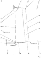
- FIG. 1 is a side view of an annular space 1 of a turbomachine according to the invention for guiding a pump flow 2 in the region of a blade grid 4, here a blade grid, shown.
- the primary stream 2 flows through the annular space 1 according to the arrow from left to right.
- the turbomachine is, for example, an aircraft engine and in addition to the annular space 1 has a stator, not shown, and a rotor, not shown, which is mounted rotatably about an indicated axis of rotation 6 in the stator.
- the annular space 1 is limited relative to the axis of rotation 6 of the rotor radially outwardly from a stator side wall 8 and radially inwardly from a rotor-side side wall 10.
- the blade grid 4 is rotatably connected to the rotor and forms with its radially inner platform ring part of the rotor side side wall 10.
- Part of the stator side wall 8 is formed in this embodiment by a radially outer platform ring of the blade grid 4, but can also by stator inlet elements for Blade tips of the blade grid 4 may be formed.
- the blade grid 4 has a plurality of blades 12 which are arranged side by side in the circumferential direction.
- Each blade 12 forms with its own radially inner platform and here also with its radially outer platform a portion of the platform rings.
- two radial annular space extensions 18, 20 extend downstream to the rear area 22, 24 of the blade grid 4, following the ideal aerodynamic annular space contour 14, 16.
- An ideal aerodynamic annular space contour 14, 16 is understood to be a cavity-free or an axially gap-free annular space that corresponds to an extrapolation or, in essence, an extrapolation of the stator-side and rotor-side side walls 8, 10. By virtue of cavity-free formation, the ideal aerodynamic annular space contour 14, 16 continues essentially without any jump or kink between adjacent airfoil gratings 4.
- the radial annular space extensions 18, 20 increase a lattice control volume at the inlet of the blade lattice 4 and thereby lower a flow velocity at the inlet and in the direction of the downstream regions 22, 24 of the blade lattice 4. This also reduces a mean Mach number level in the entire lattice control volume. Since pressure losses are in first approximation proportional to the square of the speed, they therefore decrease. A potential loss through the radial annular extensions 18, 20 is thereby overcompensated. In addition, a noise development of the turbomachine is reduced at lower speeds.
- the one annular space extension 18 is stator-side, and the other annular space extension 20 is formed on the rotor side.
- an annular space extension is formed on both sides or on both sides. They are achieved by resetting the stator-side side wall 8 and the rotor-side side wall 10.
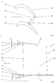
- FIG. 2 Deckringverstructure 25, 27 drawn by a conventional blade grid at the same position.
- the stator-side annular space extension 18 is preferably carried out such that the radially outer platform ring of the blade grid 4 is radially outwardly offset on the inlet side and in the direction of the rear portion 22 a stepless, radially inwardly directed course until the radially outer platform ring terminates in its rear region 22, the ideal aerodynamic annular space contour 14 follows.
- the rotor-side annular expansion 20 preferably takes place stepwise on the inlet side of the radially inner platform ring of the blade grid 4, wherein the radially inner platform ring downstream of a step 26 shows a stepless course which lies radially inward to the ideal aerodynamic annular space contour 16. Downstream of step 26, the radially inner platform ring transitions radially outward into the rear region 24, which follows the ideal aerodynamic annular space contour 16.
- leading edges 28 of the blades 12 are radially extended compared to leading edges in comparison to blades that would follow at the same position of the ideal aerodynamic annular space contour 14, 16.
- the leading edges 28 of the blades have experienced a total elongation lri + lra of at least 2%, in particular about 5%.
- Trailing edges 30 of the blades 12 remain unchanged due to the relative to the ideal aerodynamic annular space contour 14, 16 following rear portions 22, 24 unchanged or compared to conventional blades at the same position.
- the turbine-side radial annular space extensions 18, 20 preferably extend to a constriction 36 between two adjacent blades 12, 34 of the blade grid.
- the constriction 36 is located at the smallest distance a between the adjacent blades 12, 34 and generally represents a smallest cross-sectional area of a flow channel bounded in the circumferential direction by two adjacent blades 12, 34.
- the smallest distance a is determined by the felling of the solder from a suction side section 38 of the one blade 34 to the trailing edge 30 of the adjacent blade 12.
- the constriction 36 is thus arranged on the outlet side on the turbine-side blade grid 4.
- a virtual contact line 40 is taken as an axial boundary for the annular space extensions 18, 20.
- the virtual contact line 40 is arranged centrally in the constriction 36 between the blades 12, 34 and extends in the circumferential direction. It is arranged in particular upstream of the trailing edges 30 and thus axially spaced from them (see also FIG. 1 ), so that the trailing edges 30 are in the areas 22, 24, which follow the ideal aerodynamic annular space contour 14, 16.
- FIG. 3 is an annular space 1 of a turbomachine in the areas of a compressor-side blade grid 4, in particular a guide vane, with a stator-side annular space extension 18 and with a rotor-side annular space extension 20 shown.
- the annular space extensions 18, 20 are in each case implemented by radial resetting of side walls 8, 10 of the annular space 1 in relation to an ideal aerodynamic annular space contour 14, 16.
- the side walls 8, 10 are formed in the region of the blade lattice 4 by a radially outer platform ring and by a radially inner platform ring of the blade lattice 4.
- stator-side annular space extension 18 and the radially outer platform ring is formed continuously similar to the previous embodiment.
- the rotor-side annular expansion 20 is also infinitely variable, in contrast to the previous embodiment, so that an inlet side radially inwardly offset platform ring of the blade grid 4 is steplessly and steplessly directed radially outward in its rear region 24 at the height of the ideal aerodynamic annular space contour 14 passes.
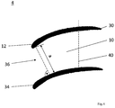
- the compressor-side radial annulus extensions 18, 20 extend in contrast to the turbine-side radial annulus extensions preferably not only to the constriction 36 between two adjacent blades 12, 34 of the blade grid 4, but significantly beyond this, since the constriction 36 at the compressor side blade grid 4th is arranged on the inlet side.
- the radial annular extensions 18, 20 extend in a compressor-side blade grid 4 up to a grid width of about 70%, ie, the rear, the ideal aerodynamic annular space contours 18, 20 subsequent areas 22, 24 of the at least one blade grid 4 correspond to the difference to the total grid width, that is, in the embodiment shown here, preferably about 30%.
- each annulus extension 18, 20 done by itself in front of the blade grid 4 and thus already in the range of a stator-side or rotor-side sowandungsabitess, which is disposed upstream of the blade grid 4.
- a turbomachine having a stator, with a rotatable about a rotation axis rotor, and having an annulus for guiding a primary current having a stator side wall and a rotor side wall and in which at least one blade grid is arranged with a plurality of blades, wherein deviating from an ideal aerodynamic annulus contour, upstream of the vanes, a radial annulus extension commences which extends downstream to a rear portion of the airfoil following the ideal aerodynamic annulus contour and a vane for such a turbomachine.
Landscapes
- Engineering & Computer Science (AREA)
- Mechanical Engineering (AREA)
- General Engineering & Computer Science (AREA)
- Physics & Mathematics (AREA)
- Fluid Mechanics (AREA)
- Structures Of Non-Positive Displacement Pumps (AREA)
Abstract
Description
- Die Erfindung betrifft eine Strömungsmaschine nach dem Oberbegriff des Patentanspruchs 1 und eine Schaufel für eine Strömungsmaschine.
- In Strömungsmaschinen bzw. Turbomaschinen wie Flugtriebewerken und stationäre Gasturbinen wird ein wesentlicher Verlustanteil durch eine verzögerte Strömung im gasführenden Strömungskanal bzw. Ringraum verursacht. In Abhängigkeit von zulässigen Verzögerungswerten führt dies mit einem idealen Ringraum zu entsprechenden geometrischen Einschränkungen.
- Zur Reduzierung von Strömungsverlusten im Ringraum ist in der
EP 0 943 784 A1 eine axiale Strömungsmaschine mit mehrstufiger Beschaufelung gezeigt, deren von einer rotorseitigen Seitenwandung und von einer statorseitigen Seitenwandung gebildete Ringraumkontur rotorseitig in Axialrichtung periodisch wellenförmig ausgebildet ist und die gegenüberliegend zu einer rotorseitigen Erhebung eine statorseitige Vertiefung aufweist. - Aus der
EP 0 799 973 A1 ist eine Strömungsmaschine mit einer Ringraumkontur bekannt, die unmittelbar am Austritt eines Laufschaufelgitters einen Knickwinkel aufweist, der so bemessen sein soll, dass eine Abströmung aus dem Laufschaufelgitter bezüglich Totaldruck und Abströmwinkel homogenisiert wird. Ein nachfolgendes Leitschaufelgitter ist eintrittsseitig mit einem korrespondierenden Gegenwinkel versehen. - Aufgabe der Erfindung ist es, eine Strömungsmaschine mit reduzierten Strömungsverlusten im Ringraum und eine Schaufel für eine derartige Strömungsmaschine zu schaffen.
- Diese Aufgabe wird gelöst durch eine Strömungsmaschine mit den Merkmalen des Patentanspruchs 1 und durch eine Schaufel mit den Merkmalen des Patentanspruchs 10.
- Eine erfindungsgemäße Strömungsmaschine hat einen Stator, einen um eine Drehachse rotierbaren Rotor und einen Ringraum zum Führen eines Primärstroms. Der Ringraum wird durch eine statorseitige Seitenwandung und durch eine rotorseitige Seitenwandung begrenzt. In dem Ringraum ist zumindest ein Schaufelgitter mit einer Vielzahl von Schaufeln angeordnet. Erfindungsgemäß beginnt abweichend von einer idealaerodynamischen Ringraumkontur stromaufwärts von den Schaufeln eine radiale Ringraumerweiterung, die sich stromabwärts bis zu einem hinteren Bereich des Schaufelgitters erstreckt, der der idealaerodynamischen Ringraumkontur folgt.
- Unter einer "idealaerodynamischen Ringraumkontur" wird bei den Temperaturen und der Drehzahl gemäß dem aerodynamischen Auslegungspunkt ein kavitätenfreier bzw. ein axialspaltfreier Ringraum verstanden, der einer Extrapolation bzw. im Wesentlichen einer Extrapolation der statorseitigen und rotorseitigen Seitenwandungen entspricht. Durch die kavitätenfreie Ausbildung setzt sich die idealaerodynamische Ringraumkontur im Wesentlichen ohne Sprung oder Knick zwischen zwei Schaufelgittern fort.
- Durch die zumindest eine radiale Ringraumerweiterung wird ein Gitterkontrollvolumen am Eintritt des Schaufelgitters vergrößert und hierdurch eine Strömungsgeschwindigkeit am Eintritt und in Richtung des stromabwärtigen Bereich des Schaufelgitters abgesenkt. Damit sinkt auch ein mittleres Machzahlniveau im gesamten Gitterkontrollvolumen. Da Druckverluste in erster Näherung proportional zum Quadrat der Geschwindigkeit sind, nehmen diese ab. Ein potenzieller Verlust durch die Ringraumerweiterung wird dadurch überkompensiert. Zustätzlich wird bei kleineren Geschwindigkeiten eine Lärmentwicklung der Strömungsmaschine reduziert. Die radiale Ringraumerweiterung ist sowohl verdichterseitig, als auch turbinenseitig, insbesondere auch in der Hochdruckturbine (HDT), in einem umlenkenden Gitter hinter der HDT zum Turbine Mid Turbine Frame (TMTF), in einem nicht umlenkenden Gitter im sogenannten Turbine Center Frame (TCF), in der Niederdruckturbine (NDT) und im sogenannten Turbine Exit Casing (TEC), ausbildbar, so dass über den gesamten Primärstrom eine jeweils relevante Verzögerung reduziert werden kann.
- Dabei wird der Effekt ausgenutzt, dass bei Schaufelgittern häufig eine Kavität vorhanden ist, an der immer wieder eine Grenzschicht neu startet. Dies wird genutzt, um eine effektive Querschnittsfläche für den Ringraum zu erweitern und von einer ursprünglichen Ringraumform abzuweichen. Damit wird das lokale Geschwindigkeitsniveau am Eintritt und das mittlere Geschwindigkeitsniveau im Gitterkontrollvolumen abgesenkt, wodurch einhergehend aero-thermodynamische Verluste reduziert werden.
- Wenn die zumindest eine radiale Ringraumerweiterung turbinenseitig ausgebildet ist, ist es vorteilhaft, wenn sich die radiale Ringraumerweiterung bis zu einer Engstelle zwischen zwei benachbarten Schaufeln erstreckt. Die Engstelle ist dabei der Bereich mit dem kleinsten Abstand zwischen zwei benachbarten Schaufeln.
- Wenn die zumindest eine radiale Ringraumerweiterung verdichterseitig ausgebildet ist, wird es bevorzugt, wenn die radiale Ringraumerweiterung in etwa 70%, d.h. zwischen 65% und 75%, der Gitterbreite umfasst. Der hintere, der idealaerodynamischen Ringraumkontur folgende Bereich des zumindest einen Schaufelgitters entspricht dabei der Differenz zur gesamten Gitterbreite, also hier etwa 30%.
- Bei einem alternativen Ausführungsbeispiel ist die Ringraumerweiterung zweiseitig bzw. beidseits, also statorseitig und rotorseitig, ausgebildet. Es wird also eine statorseitige Ringraumerweiterung und eine rotorseitige Ringraumerweiterung gebildet bzw. die Ringraumerweiterung hat einen statorseitigen zurückgesetzten Abschnitt und einen rotorseitig zurückgesetzten Abschnitt. Durch diese Maßnahme lässt sich das Gitterkontrollvolumen im Vergleich zur einseitigen Ringraumerweiterung mindestens verdoppeln, gleichzeitig jedoch eine radial versetzte Anströmung des Schaufelgitters verhindern.
- Bevorzugterweise zeigt ein Seitenwandungsabschnitt, der die zumindest eine radiale Ringraumerweiterung radial außen begrenzt, einen stufenlosen Verlauf. Der Seitenwandungsabschnitt kann dabei sowohl statorseitig, als auch rotorseitig ausgebildet sein.
- Ein alternativer Seitenwandungsabschnitt zeigt einen stufenartigen Verlauf. Durch den stufenartigen Verlauf wird im Vergleich zum stufenlosen Verlauf die Ringraumerweiterung sprunghaft reduziert.
- Bevorzugterweise haben die Schaufeln durch die Ringraumerweiterung eine um mindestens 2% verlängerte Vorderkante im Vergleich zu Schaufeln, die an gleicher Position der idealaerodynamischen Ringraumkontur folgen würden. Insbesondere wird es bevorzugt, wenn die Schaufeln eine um mindestens 5% verlängerte Vorderkante haben. Es hat sich jedoch auch eine um 14% verlängerte Vorderkante als vorteilhaft erwiesen. Der idealaerodynamische Ringraum schneidet die Vorderkanten durch ihre Verlängerung nicht in einem Bereich, in dem die Vorderkanten in die Seitenwandungen übergehen, sondern in einem Punkt, der von den Seitenwandungen radial beabstandet bzw. von den Seitenwandungen aus betrachtet radial weg von einer Ringraummitte versetzt ist.
- Bevorzugterweise weisen zumindest zwei benachbarte Schaufelgitter die radiale Ringraumerweiterung auf. Hierdurch kommt es beim Übergang von einem Schaufelgitter zu einem benachbarten stromabwärtigen Schaufelgitter, welches die radiale Ringraumerweiterung aufweist, zu einem sogenannten "Rücksprung" im Ringraum gegenüber einem ideal aerodynamischen Ringraum.
- Zusätzlich zur radialen Ringraumerweiterung können lokale Seitenwandkonturierungen wie Erhebungen und Vertiefungen vorgesehen sein. Bezogen werden die Seitenwandkonturierungen bevorzugterweise auf ein Nullniveau ohne Seitenwandkonturierung für den idealaerodynamischen Ringraum.
- Eine erfindungsgemäße Schaufel hat zumindest eine Plattformkontur mit einem vorderen Bereich, die gegenüber einer idealaerodynamischen Ringraumkontur radial erweitert ist, und mit einem hinteren Bereich, der der idealaerodynamischen Ringraumkontur folgt und in den der vorderer Bereich übergeht. Durch diese Maßnahme wird beginnend am stromaufwärtigen Bereich eines Leit- oder Laufgitters gegenüber einem idealaerodynamischen Ringraum der Ringraum aufgeweitet, wobei entweder die radial innere Seitenwandung nach radial innen abgesenkt und/oder die radial äußere Seitenwandung nach radial außen angehoben wird.
- Sonstige vorteilhafte Ausführungsbeispiele der Erfindung sind Gegenstand weiterer Unteransprüche.
- Im Folgenden werden bevorzugte Ausführungsbeispiele der Erfindung anhand von schematischen Darstellungen näher erläutert. Es zeigen:
- Figur 1
- ein Ausführungsbeispiel eines Ringraums einer Strömungsmaschine im Bereich einer erfindungsgemäßen radialen Ringraumerweiterung, die stromaufwärts eines turbinenseitigen Laufschaufelgitters beginnt,
- Figur 2
- eine Draufsicht auf einen abgewinkelten Umfangsabschnitt des turbinenseitigen Schaufelgitters aus
Figur 1 , - Figur 3
- ein Ausführungsbeispiel eines Ringraums einer Strömungsmaschine im Bereich einer erfindungsgemäßen radialen Ringraumerweiterung, die stromaufwärts eines verdichterseitigen Schaufelgitters beginnt, und
- Figur 4
- eine Draufsicht auf einen abgewinkelten Umfangsabschnitt des verdichterseitigen Schaufelgitters aus
Figur 3 . - In
Figur 1 ist eine Seitenansicht eines Ringraums 1 einer erfindungsgemäßen Strömungsmaschine zum Führen eines Pumärstroms 2 im Bereich eines Schaufelgitters 4, hier ein Laufschaufelgitter, gezeigt. Der Primärstrom 2 durchströmt den Ringraum 1 gemäß der Pfeildarstellung von links nach rechts. Die Strömungsmaschine ist beispielsweise ein Flugtriebwerk und hat neben den Ringraum 1 einen nicht gezeigten Stator und einen nicht gezeigten Rotor, der um eine angedeutete Drehachse 6 rotierbar in dem Stator gelagert ist. - Der Ringraum 1 wird bezogen auf die Drehachse 6 des Rotors radial außen von einer statorseitigen Seitenwandung 8 und radial innen von einer rotorseitigen Seitenwandung 10 begrenzt. Das Schaufelgitter 4 ist drehfest mit dem Rotor verbunden und bildet mit seinem radial inneren Plattformring einen Teil der rotorseitigen Seitenwandung 10. Ein Teil der statorseitigen Seitenwandung 8 wird in diesem Ausführungsbeispiel von einem radial äußeren Plattformring des Schaufelgitters 4 gebildet, kann jedoch auch von statorseitigen Einlaufelementen für Schaufelspitzen des Schaufelgitters 4 gebildet sein.
- Das Schaufelgitter 4 hat eine Vielzahl von Schaufeln 12, die in Umfangsrichtung nebeneinander angeordnet sind. Jede Schaufel 12 bildet dabei mit seiner eigenen radial inneren Plattform und hier auch mit seiner radial äußeren Plattform einen Abschnitt der Plattformringe.
- Erfindungsgemäß beginnen abweichend von einer strichpunktiert dargestellten idealaerodynamischen Ringraumkontur 14, 16 stromaufwärts von den Schaufeln 4 zwei radiale Ringraumerweiterung 18, 20, die sich stromabwärts bis zu einem hinteren Bereich 22, 24 des Schaufelgitters 4 erstreckt, der der idealaerodynamischen Ringraumkontur 14, 16 folgen.
- Unter einer idealaerodynamischen Ringraumkontur 14, 16 wird dabei ein kavitätenfreier bzw. ein axialspaltfreier Ringraum verstanden, der einer Extrapolation bzw. im Wesentlichen einer Extrapolation der statorseitigen und rotorseitigen Seitenwandungen 8, 10 entspricht. Durch kavitätenfreie Ausbildung setzt sich die idealaerodynamische Ringraumkontur 14, 16 im Wesentlichen ohne Sprung oder Knick zwischen benachbarten Schaufelgittern 4 fort.
- Durch die radiale Ringraumerweiterungen 18, 20 werden ein Gitterkontrollvolumen am Eintritt des Schaufelgitters 4 vergrößert und hierdurch eine Strömungsgeschwindigkeit am Eintritt und in Richtung der stromabwärtigen Bereiche 22, 24 des Schaufelgitters 4 abgesenkt. Damit sinkt auch ein mittleres Machzahlniveau im gesamten Gitterkontrollvolumen. Da Druckverluste in erster Näherung proportional zum Quadrat der Geschwindigkeit sind, nehmen diese daher ab. Ein potenzieller Verlust durch die radiale Ringraumerweiterungen 18, 20 wird dadurch überkompensiert. Zustäzlich wird bei kleineren Geschwindigkeiten eine Lärmentwicklung der Strömungsmaschine reduziert.
- Die eine Ringraumerweiterung 18 ist statorseitig, und die andere Ringraumerweiterung 20 ist rotorseitig ausgebildet. Grundsätzlich lässt sich auch sagen, dass eine Ringraumerweiterung zweiseitig bzw. beidseits ausgebildet. Sie werden durch eine Zurücksetzung der statorseitigen Seitenwandung 8 und der rotorseitigen Seitenwandung 10 erreicht. Zur grafischen Verdeutlichung der Ringraumerweiterungen sind in
Figur 2 Plattformringverläufe 25, 27 von einem herkömmlichen Schaufelgitter an gleicher Position eingezeichnet. - Die statorseitige Ringraumerweiterung 18 erfolgt bevorzugterweise derart, dass der radial äußere Plattformring des Schaufelgitters 4 eintrittsseitig radial nach außen versetzt ist und in Richtung des hinteren Bereichs 22 einen stufenlosen, radial nach innen gerichtet Verlauf zeigt bis der radial äußere Plattformring in seinen hinteren Bereich 22 ausläuft, der idealaerodynamischen Ringraumkontur 14 folgt.
- Die rotorseitige Ringraumerweiterung 20 erfolgt bevorzugterweise eintrittsseitig des radial inneren Plattformrings des Schaufelgitters 4 stufenförmig, wobei der radial innere Plattformring stromabwärts einer Stufe 26 einen stufenlosen Verlauf zeigt, die radial innen zur idealaerodynamischen Ringraumkontur 16 liegt. Stromabwärts der Stufe 26 geht der radial innere Plattformring radial nach außen gerichtet in den hinteren Bereich 24 über, der der idealaerodynamiachen Ringraumkontur 16 folgt.
- Als konstruktive Folge der zweiseitigen radialen Ringraumerweiterung 18, 20 werden Vorderkanten 28 der Schaufeln 12 radial gegenüber Vorderkanten im Vergleich zu Schaufeln, die an gleicher Position der idealaerodynamischen Ringraumkontur 14, 16 folgen würden, verlängert. Bevorzugterweise haben die Vorderkanten 28 der Schaufeln eine Gesamtverlängerung lri + lra um mindestens 2%, insbesondere um 5% erfahren. Hinterkanten 30 der Schaufeln 12 bleiben aufgrund der gegenüber der idealaerodynamischen Ringraumkontur 14, 16 folgendem hinteren Bereichen 22, 24 unverändert bzw. unverlängert gegenüber herkömmlichen Schaufeln an gleicher Position.
- Wie anhand eines abgewickelten Umfangsabschnitts des Schaufelgitters 4 in
Figur 2 mit Blick auf den inneren Plattformring 10 skizziert, erstrecken sich die turbinenseitigen radialen Ringraumerweiterungen 18, 20 bevorzugterweise bis zu einer Engstelle 36 zwischen zwei benachbarten Schaufeln 12, 34 des Schaufelgitters. Die Engstelle 36 befindet sich im kleinsten Abstand a zwischen den benachbarten Schaufeln 12, 34 und repräsentiert allgemein eine kleinste Querschnittsfläche eines Strömungskanals, der in Umfangsrichtung von zwei benachbarten Schaufeln 12, 34 begrenzt wird. Der kleinste Abstand a wird durch das Fällen des Lotes von einem Saugseitenabschnitt 38 der einen Laufschaufel 34 zur Hinterkante 30 der benachbarten Schaufel 12 bestimmt. Die Engstelle 36 ist beim turbinenseitigen Schaufelgitter 4 somit austrittseitig angeordnet. Dabei wird eine virtuelle Berührungslinie 40 als axiale Begrenzung für die Ringraumerweiterungen 18, 20 genommen. Die virtuelle Berührungslinie 40 ist mittig der Engstelle 36 zwischen den Schaufeln 12, 34 angeordnet und erstreckt sich in Umfangsrichtung. Sie ist insbesondere stromaufwärts der Hinterkanten 30 angeordnet und somit von diesen axial beabstandet (siehe auchFigur 1 ), so dass sich die Hinterkanten 30 in den Bereichen 22, 24 befinden, die der idealaerodynamischen Ringraumkontur 14, 16 folgen. - In
Figur 3 ist ein Ringraum 1 einer Strömungsmaschine im Bereiche eines verdichterseitigen Schaufelgitters 4, insbesondere ein Leitschaufelgitter, mit einer statorseitigen Ringraumerweiterung 18 und mit einer rotorseitigen Ringraumerweiterung 20 gezeigt. Die Ringraumerweiterungen 18, 20 sind gegenüber einer idealaerodynamischen Ringraumkontur 14, 16 jeweils durch radiale Zurücksetzungen von Seitenwandungen 8, 10 des Ringraums 1 ausgeführt. Die Seitenwandungen 8, 10 werden im Bereich des Schaufelgitters 4 von einem radial äußeren Plattformring und von einem radial inneren Plattformring des Schaufelgitters 4 gebildet. - Die statorseitige Ringraumerweiterung 18 bzw. der radial äußere Plattformring ist ähnlich zum vorhergehenden Ausführungsbeispiel stufenlos ausgebildet. Die rotorseitige Ringraumerweiterung 20 ist im Unterschied zum vorhergehenden Ausführungsbeispiel ebenfalls stufenlos, so dass ein eintrittsseitig radial nach innen versetzter Plattformring des Schaufelgitters 4 stufenlos verläuft ist und ebenso stufenlos radial nach außen gerichtet in seinen hinteren Bereich 24 auf Höhe der idealaerodynamischen Ringraumkontur 14 übergeht.
- Wie in
Figur 4 skizziert, erstrecken sich die verdichterseitigen radialen Ringraumerweiterungen 18, 20 im Unterschied zu den turbinenseitigen radialen Ringraumerweiterungen bevorzugterweise nicht nur bis zur Engstelle 36 zwischen zwei benachbarten Schaufeln 12, 34 des Schaufelgitters 4, sondern deutlich über diese hinaus, da die Engstelle 36 beim verdichterseitigen Schaufelgitter 4 eintrittsseitig angeordnet ist. Bevorzugterweise erstrecken sich die radialen Ringraumerweiterungen 18, 20 bei einem verdichterseitigen Schaufelgitter 4 bis zu einer Gitterbreite von etwa 70%, d.h. die hinteren, den idealaerodynamischen Ringraumkonturen 18, 20 folgenden Bereiche 22, 24 des zumindest einen Schaufelgitters 4 entsprechen der Differenz zur gesamten Gitterbreite, also in dem hier gezeigten Ausführungsbeispiel bevorzugterweise etwa 30%. - Selbstverständlich kann bei den in den
Figuren 1 bis 4 erläuterten Ausführungsbeispielen jede Ringraumerweiterung 18, 20 für sich auch vor dem Schaufelgitter 4 und somit bereits im Bereich eines statorseitigen bzw. rotorseitigen Seitenwandungsabschnitts erfolgen, der stromaufwärts benachbart zum Schaufelgitter 4 angeordnet ist. - Offenbart ist eine Strömungsmaschine, mit einem Stator, mit einem um eine Drehachse rotierbaren Rotor, und mit einem Ringraum zum Führen eines Primärstroms, der eine statorseitige Seitenwand und eine rotorseitige Seitenwand hat und in dem zumindest ein Schaufelgitter mit einer Vielzahl von Schaufeln angeordnet ist, wobei abweichend von einer idealaerodynamischen Ringraumkontur stromaufwärts von den Schaufeln eine radiale Ringraumerweiterung beginnt, die sich stromabwärts bis zu einem hinteren Bereich des Schaufelgitters erstreckt, der der idealaerodynamischen Ringraumkontur folgt, sowie eine Schaufel für eine derartige Strömungsmaschine.
-
- 1
- Ringraum
- 2
- Primärstrom
- 4
- Schaufelgitter
- 6
- Drehachse
- 8
- statorseitige Seitenwandung
- 10
- rotorseitige Seitenwandung
- 12
- Schaufel
- 14
- idealaerodynamische Ringraumkontur
- 16
- idealaerodynamische Ringraumkontur
- 18
- Ringraumerweiterung
- 20
- Ringraumerweiterung
- 22
- hinterer Bereich
- 24
- hinterer Bereich
- 25
- herkömmlicher Seitenwandungsverlauf
- 26
- Stufe
- 27
- herkömmlicher Seitenwandungsverlauf
- 28
- Vorderkante
- 30
- Hinterkante
- 34
- Schaufel
- 36
- Engstelle
- 38
- Saugseitenabschnitt
- 40
- Berührungslinie
- a
- Abstand
- lri
- radial innere Verlängerung
- lra
- radial äußere Verlängerung
Claims (10)
- Strömungsmaschine, mit einem Stator, mit einem um eine Drehachse (6) rotierbaren Rotor, und mit einem Ringraum zum Führen eines Primärstroms (2), der eine statorseitige Seitenwandung (8) und eine rotorseitige Seitenwandung (10) hat und in dem zumindest ein Schaufelgitter (4) mit einer Vielzahl von Schaufeln (12) angeordnet ist, dadurch gekennzeichnet, dass abweichend von einer idealaerodynamischen Ringraumkontur (14, 16) stromaufwärts von den Schaufeln (12) eine radiale Ringraumerweiterung (18, 20) beginnt, die sich stromabwärts bis zu einem hinteren Bereich (22, 24) des Schaufelgitters (4) erstreckt, der der idealaerodynamischen Ringraumkontur (14, 16) folgt.
- Strömungsmaschine nach Patentanspruch 1, wobei der sich die Ringraumerweiterung (18, 20) bis zu einer Engstelle (36) zwischen zwei benachbarten Schaufeln (12) des Schaufelgitters (4) erstreckt.
- Strömungsmaschine nach Patentanspruch 1, wobei die Ringraumerweiterung (18, 20) etwa 70% der Gitterbreite umfasst.
- Strömungsmaschine nach Patentanspruch 1, 2 oder 3, wobei die Ringraumerweiterung (18, 20) zweiseitig ausgebildet ist.
- Strömungsmaschine nach einem der vorhergehenden Patentansprüche, wobei ein die Ringraumerweiterung (18, 20) begrenzender Abschnitt der Seitenwandung (8) einen stufenlosen Verlauf zeigt.
- Strömungsmaschine nach einem der Patentansprüche 1 bis 4, wobei ein die Ringraumerweiterung (18, 20) begrenzender Abschnitt der Seitenwandung (10) einen stufenartigen Verlauf zeigt.
- Strömungsmaschine nach einem der vorhergehenden Patentansprüche, wobei die Schaufeln (12) durch die Ringraumerweiterung (18, 20) eine um mindestens 2% verlängerte Vorderkante (28) im Vergleich zu Schaufeln (12) haben, die an gleicher Position der idealaerodynamischen Ringraumkontur (14, 16) folgen würden.
- Strömungsmaschine nach einem der vorhergehenden Patentansprüche, wobei zumindest zwei benachbarte Schaufelgitter (4) die Ringraumerweiterung (18, 20) aufweisen.
- Strömungsmaschine nach einem der vorhergehenden Patentansprüche, wobei lokale Seitenwandkonturierungen ausgebildet sind.
- Schaufel (12) für eine Strömungsmaschine nach einem der vorhergehenden Patentansprüche.
Applications Claiming Priority (1)
| Application Number | Priority Date | Filing Date | Title |
|---|---|---|---|
| DE102014225689.5A DE102014225689A1 (de) | 2014-12-12 | 2014-12-12 | Strömungsmaschine mit Ringraumerweiterung und Schaufel |
Publications (2)
| Publication Number | Publication Date |
|---|---|
| EP3043022A1 true EP3043022A1 (de) | 2016-07-13 |
| EP3043022B1 EP3043022B1 (de) | 2023-10-18 |
Family
ID=54707680
Family Applications (1)
| Application Number | Title | Priority Date | Filing Date |
|---|---|---|---|
| EP15196895.5A Active EP3043022B1 (de) | 2014-12-12 | 2015-11-27 | Strömungsmaschine mit ringraumerweiterung und schaufel |
Country Status (4)
| Country | Link |
|---|---|
| US (1) | US10570743B2 (de) |
| EP (1) | EP3043022B1 (de) |
| DE (1) | DE102014225689A1 (de) |
| ES (1) | ES2964365T3 (de) |
Citations (6)
| Publication number | Priority date | Publication date | Assignee | Title |
|---|---|---|---|---|
| EP0799973A1 (de) | 1996-04-01 | 1997-10-08 | Asea Brown Boveri Ag | Wandkontur für eine axiale Strömungsmaschine |
| EP0943784A1 (de) | 1998-03-19 | 1999-09-22 | Asea Brown Boveri AG | Konturierter Kanal einer axialen Strömungsmaschine |
| EP1126132A2 (de) * | 2000-02-18 | 2001-08-22 | General Electric Company | Radiale Strömungskanalwand mit Einstülpungen für einen Verdichter |
| EP1382797A2 (de) * | 2002-07-20 | 2004-01-21 | Rolls-Royce Deutschland Ltd & Co KG | Strömungs-Arbeits-Maschine mit überhöhtem Rotor-Stator-Kontraktionsverhältnis |
| DE102007020025A1 (de) * | 2007-04-27 | 2008-10-30 | Honda Motor Co., Ltd. | Form eines Gaskanals in einer Axialströmungs-Gasturbinenmaschine |
| DE102011076804A1 (de) * | 2011-05-31 | 2012-12-06 | Honda Motor Co., Ltd. | Innenumfangsflächenform eines Axialverdichtergehäuses |
Family Cites Families (12)
| Publication number | Priority date | Publication date | Assignee | Title |
|---|---|---|---|---|
| FR996967A (fr) * | 1949-09-06 | 1951-12-31 | Rateau Soc | Perfectionnement aux aubages de turbomachines |
| ZA8234B (en) | 1981-01-05 | 1982-11-24 | Alsthom Atlantique | A turbine stage |
| SE9904603D0 (sv) | 1999-12-16 | 1999-12-16 | Atlas Copco Tools Ab | Turbine motor for elastic fluid operation |
| US6508630B2 (en) | 2001-03-30 | 2003-01-21 | General Electric Company | Twisted stator vane |
| JP2002371802A (ja) * | 2001-06-14 | 2002-12-26 | Mitsubishi Heavy Ind Ltd | ガスタービンにおけるシュラウド一体型動翼と分割環 |
| US7189056B2 (en) | 2005-05-31 | 2007-03-13 | Pratt & Whitney Canada Corp. | Blade and disk radial pre-swirlers |
| WO2009019282A2 (de) | 2007-08-06 | 2009-02-12 | Alstom Technology Ltd | Spaltkühlung zwischen brennkammerwand und turbinenwand einer gasturbinenanlage |
| DE102008060847B4 (de) | 2008-12-06 | 2020-03-19 | MTU Aero Engines AG | Strömungsmaschine |
| GB201011854D0 (en) | 2010-07-14 | 2010-09-01 | Isis Innovation | Vane assembly for an axial flow turbine |
| US8602740B2 (en) | 2010-09-08 | 2013-12-10 | United Technologies Corporation | Turbine vane airfoil |
| JP2012233406A (ja) | 2011-04-28 | 2012-11-29 | Hitachi Ltd | ガスタービン静翼 |
| US9175567B2 (en) | 2012-02-29 | 2015-11-03 | United Technologies Corporation | Low loss airfoil platform trailing edge |
-
2014
- 2014-12-12 DE DE102014225689.5A patent/DE102014225689A1/de not_active Ceased
-
2015
- 2015-11-27 EP EP15196895.5A patent/EP3043022B1/de active Active
- 2015-11-27 ES ES15196895T patent/ES2964365T3/es active Active
- 2015-12-11 US US14/966,121 patent/US10570743B2/en active Active
Patent Citations (6)
| Publication number | Priority date | Publication date | Assignee | Title |
|---|---|---|---|---|
| EP0799973A1 (de) | 1996-04-01 | 1997-10-08 | Asea Brown Boveri Ag | Wandkontur für eine axiale Strömungsmaschine |
| EP0943784A1 (de) | 1998-03-19 | 1999-09-22 | Asea Brown Boveri AG | Konturierter Kanal einer axialen Strömungsmaschine |
| EP1126132A2 (de) * | 2000-02-18 | 2001-08-22 | General Electric Company | Radiale Strömungskanalwand mit Einstülpungen für einen Verdichter |
| EP1382797A2 (de) * | 2002-07-20 | 2004-01-21 | Rolls-Royce Deutschland Ltd & Co KG | Strömungs-Arbeits-Maschine mit überhöhtem Rotor-Stator-Kontraktionsverhältnis |
| DE102007020025A1 (de) * | 2007-04-27 | 2008-10-30 | Honda Motor Co., Ltd. | Form eines Gaskanals in einer Axialströmungs-Gasturbinenmaschine |
| DE102011076804A1 (de) * | 2011-05-31 | 2012-12-06 | Honda Motor Co., Ltd. | Innenumfangsflächenform eines Axialverdichtergehäuses |
Also Published As
| Publication number | Publication date |
|---|---|
| US10570743B2 (en) | 2020-02-25 |
| US20160168998A1 (en) | 2016-06-16 |
| EP3043022B1 (de) | 2023-10-18 |
| DE102014225689A1 (de) | 2016-07-14 |
| ES2964365T3 (es) | 2024-04-05 |
Similar Documents
| Publication | Publication Date | Title |
|---|---|---|
| EP2025946B1 (de) | Schaufeldeckband mit Sperrstrahlerzeugung | |
| EP2746533B1 (de) | Schaufelgitter und Strömungsmaschine | |
| EP0799973B1 (de) | Wandkontur für eine axiale Strömungsmaschine | |
| DE10350626B4 (de) | Strompfaddichtung und Stromlinienkonfigurierung für eine Turbine | |
| EP2179143B1 (de) | Spaltkühlung zwischen brennkammerwand und turbinenwand einer gasturbinenanlage | |
| EP2927503B1 (de) | Gasturbinenverdichter, Flugtriebwerk und Auslegungsverfahren | |
| EP2146053A1 (de) | Axialturbomaschine mit geringen Spaltverlusten | |
| EP2696029A1 (de) | Schaufelgitter mit Seitenwandkonturierung und Strömungsmaschine | |
| DE102015219556A1 (de) | Diffusor für Radialverdichter, Radialverdichter und Turbomaschine mit Radialverdichter | |
| EP2947270B1 (de) | Schaufelreihengruppe | |
| DE102007020025A1 (de) | Form eines Gaskanals in einer Axialströmungs-Gasturbinenmaschine | |
| EP3032032B1 (de) | Austrittsleitgitter und Mantelstromtriebwerk mit einem Austrittsleitgitter | |
| EP3260660B1 (de) | Lauf- oder leitschaufel mit erhabenen bereichen | |
| EP2297430A1 (de) | Axialturbine für eine gasturbine mit geringem spiel zwischen schaufeln un gehäuse | |
| DE102014115475A1 (de) | Hinterkantenausrundung einer Gasturbinenleitschaufel | |
| EP2607625B1 (de) | Turbomaschine und turbomaschinenstufe | |
| EP3336313A1 (de) | Turbinen-laufschaufelanordnung für eine gasturbine und verfahren zum bereitstellen von dichtluft in einer turbinen-laufschaufelanordnung | |
| EP3561228B1 (de) | Schaufel, schaufelsegment und baugruppe für eine turbomaschine und turbomaschine | |
| WO2005106207A1 (de) | Verdichterschaufel und verdichter | |
| EP2597257B1 (de) | Beschaufelung | |
| WO2018166716A1 (de) | Rückführstufe und radialturbofluidenergiemaschine | |
| EP3401504B1 (de) | Schaufelgitter | |
| EP2410131A2 (de) | Rotor einer Turbomaschine | |
| EP1001138B1 (de) | Spitzendichtung für Turbinenlaufschaufeln | |
| EP3428391B1 (de) | Turbomaschinen-schaufelgitter |
Legal Events
| Date | Code | Title | Description |
|---|---|---|---|
| PUAI | Public reference made under article 153(3) epc to a published international application that has entered the european phase |
Free format text: ORIGINAL CODE: 0009012 |
|
| AK | Designated contracting states |
Kind code of ref document: A1 Designated state(s): AL AT BE BG CH CY CZ DE DK EE ES FI FR GB GR HR HU IE IS IT LI LT LU LV MC MK MT NL NO PL PT RO RS SE SI SK SM TR |
|
| AX | Request for extension of the european patent |
Extension state: BA ME |
|
| STAA | Information on the status of an ep patent application or granted ep patent |
Free format text: STATUS: REQUEST FOR EXAMINATION WAS MADE |
|
| 17P | Request for examination filed |
Effective date: 20161221 |
|
| RBV | Designated contracting states (corrected) |
Designated state(s): AL AT BE BG CH CY CZ DE DK EE ES FI FR GB GR HR HU IE IS IT LI LT LU LV MC MK MT NL NO PL PT RO RS SE SI SK SM TR |
|
| STAA | Information on the status of an ep patent application or granted ep patent |
Free format text: STATUS: EXAMINATION IS IN PROGRESS |
|
| 17Q | First examination report despatched |
Effective date: 20210531 |
|
| GRAP | Despatch of communication of intention to grant a patent |
Free format text: ORIGINAL CODE: EPIDOSNIGR1 |
|
| STAA | Information on the status of an ep patent application or granted ep patent |
Free format text: STATUS: GRANT OF PATENT IS INTENDED |
|
| INTG | Intention to grant announced |
Effective date: 20230515 |
|
| GRAS | Grant fee paid |
Free format text: ORIGINAL CODE: EPIDOSNIGR3 |
|
| GRAA | (expected) grant |
Free format text: ORIGINAL CODE: 0009210 |
|
| STAA | Information on the status of an ep patent application or granted ep patent |
Free format text: STATUS: THE PATENT HAS BEEN GRANTED |
|
| AK | Designated contracting states |
Kind code of ref document: B1 Designated state(s): AL AT BE BG CH CY CZ DE DK EE ES FI FR GB GR HR HU IE IS IT LI LT LU LV MC MK MT NL NO PL PT RO RS SE SI SK SM TR |
|
| REG | Reference to a national code |
Ref country code: GB Ref legal event code: FG4D Free format text: NOT ENGLISH |
|
| REG | Reference to a national code |
Ref country code: CH Ref legal event code: EP |
|
| REG | Reference to a national code |
Ref country code: IE Ref legal event code: FG4D Free format text: LANGUAGE OF EP DOCUMENT: GERMAN |
|
| REG | Reference to a national code |
Ref country code: DE Ref legal event code: R096 Ref document number: 502015016642 Country of ref document: DE |
|
| REG | Reference to a national code |
Ref country code: LT Ref legal event code: MG9D |
|
| REG | Reference to a national code |
Ref country code: NL Ref legal event code: MP Effective date: 20231018 |
|
| PG25 | Lapsed in a contracting state [announced via postgrant information from national office to epo] |
Ref country code: NL Free format text: LAPSE BECAUSE OF FAILURE TO SUBMIT A TRANSLATION OF THE DESCRIPTION OR TO PAY THE FEE WITHIN THE PRESCRIBED TIME-LIMIT Effective date: 20231018 |
|
| REG | Reference to a national code |
Ref country code: ES Ref legal event code: FG2A Ref document number: 2964365 Country of ref document: ES Kind code of ref document: T3 Effective date: 20240405 |
|
| PG25 | Lapsed in a contracting state [announced via postgrant information from national office to epo] |
Ref country code: GR Free format text: LAPSE BECAUSE OF FAILURE TO SUBMIT A TRANSLATION OF THE DESCRIPTION OR TO PAY THE FEE WITHIN THE PRESCRIBED TIME-LIMIT Effective date: 20240119 |
|
| PG25 | Lapsed in a contracting state [announced via postgrant information from national office to epo] |
Ref country code: IS Free format text: LAPSE BECAUSE OF FAILURE TO SUBMIT A TRANSLATION OF THE DESCRIPTION OR TO PAY THE FEE WITHIN THE PRESCRIBED TIME-LIMIT Effective date: 20240218 |
|
| PG25 | Lapsed in a contracting state [announced via postgrant information from national office to epo] |
Ref country code: LT Free format text: LAPSE BECAUSE OF FAILURE TO SUBMIT A TRANSLATION OF THE DESCRIPTION OR TO PAY THE FEE WITHIN THE PRESCRIBED TIME-LIMIT Effective date: 20231018 |
|
| PG25 | Lapsed in a contracting state [announced via postgrant information from national office to epo] |
Ref country code: LT Free format text: LAPSE BECAUSE OF FAILURE TO SUBMIT A TRANSLATION OF THE DESCRIPTION OR TO PAY THE FEE WITHIN THE PRESCRIBED TIME-LIMIT Effective date: 20231018 Ref country code: IS Free format text: LAPSE BECAUSE OF FAILURE TO SUBMIT A TRANSLATION OF THE DESCRIPTION OR TO PAY THE FEE WITHIN THE PRESCRIBED TIME-LIMIT Effective date: 20240218 Ref country code: GR Free format text: LAPSE BECAUSE OF FAILURE TO SUBMIT A TRANSLATION OF THE DESCRIPTION OR TO PAY THE FEE WITHIN THE PRESCRIBED TIME-LIMIT Effective date: 20240119 Ref country code: BG Free format text: LAPSE BECAUSE OF FAILURE TO SUBMIT A TRANSLATION OF THE DESCRIPTION OR TO PAY THE FEE WITHIN THE PRESCRIBED TIME-LIMIT Effective date: 20240118 Ref country code: PT Free format text: LAPSE BECAUSE OF FAILURE TO SUBMIT A TRANSLATION OF THE DESCRIPTION OR TO PAY THE FEE WITHIN THE PRESCRIBED TIME-LIMIT Effective date: 20240219 |
|
| PG25 | Lapsed in a contracting state [announced via postgrant information from national office to epo] |
Ref country code: SE Free format text: LAPSE BECAUSE OF FAILURE TO SUBMIT A TRANSLATION OF THE DESCRIPTION OR TO PAY THE FEE WITHIN THE PRESCRIBED TIME-LIMIT Effective date: 20231018 Ref country code: RS Free format text: LAPSE BECAUSE OF FAILURE TO SUBMIT A TRANSLATION OF THE DESCRIPTION OR TO PAY THE FEE WITHIN THE PRESCRIBED TIME-LIMIT Effective date: 20231018 Ref country code: PL Free format text: LAPSE BECAUSE OF FAILURE TO SUBMIT A TRANSLATION OF THE DESCRIPTION OR TO PAY THE FEE WITHIN THE PRESCRIBED TIME-LIMIT Effective date: 20231018 Ref country code: NO Free format text: LAPSE BECAUSE OF FAILURE TO SUBMIT A TRANSLATION OF THE DESCRIPTION OR TO PAY THE FEE WITHIN THE PRESCRIBED TIME-LIMIT Effective date: 20240118 Ref country code: LV Free format text: LAPSE BECAUSE OF FAILURE TO SUBMIT A TRANSLATION OF THE DESCRIPTION OR TO PAY THE FEE WITHIN THE PRESCRIBED TIME-LIMIT Effective date: 20231018 Ref country code: HR Free format text: LAPSE BECAUSE OF FAILURE TO SUBMIT A TRANSLATION OF THE DESCRIPTION OR TO PAY THE FEE WITHIN THE PRESCRIBED TIME-LIMIT Effective date: 20231018 |
|
| REG | Reference to a national code |
Ref country code: CH Ref legal event code: PL |
|
| PG25 | Lapsed in a contracting state [announced via postgrant information from national office to epo] |
Ref country code: DK Free format text: LAPSE BECAUSE OF FAILURE TO SUBMIT A TRANSLATION OF THE DESCRIPTION OR TO PAY THE FEE WITHIN THE PRESCRIBED TIME-LIMIT Effective date: 20231018 |
|
| PG25 | Lapsed in a contracting state [announced via postgrant information from national office to epo] |
Ref country code: LU Free format text: LAPSE BECAUSE OF NON-PAYMENT OF DUE FEES Effective date: 20231127 |
|
| PG25 | Lapsed in a contracting state [announced via postgrant information from national office to epo] |
Ref country code: CH Free format text: LAPSE BECAUSE OF NON-PAYMENT OF DUE FEES Effective date: 20231130 |
|
| REG | Reference to a national code |
Ref country code: DE Ref legal event code: R097 Ref document number: 502015016642 Country of ref document: DE |
|
| PG25 | Lapsed in a contracting state [announced via postgrant information from national office to epo] |
Ref country code: CZ Free format text: LAPSE BECAUSE OF FAILURE TO SUBMIT A TRANSLATION OF THE DESCRIPTION OR TO PAY THE FEE WITHIN THE PRESCRIBED TIME-LIMIT Effective date: 20231018 |
|
| PG25 | Lapsed in a contracting state [announced via postgrant information from national office to epo] |
Ref country code: SK Free format text: LAPSE BECAUSE OF FAILURE TO SUBMIT A TRANSLATION OF THE DESCRIPTION OR TO PAY THE FEE WITHIN THE PRESCRIBED TIME-LIMIT Effective date: 20231018 |
|
| PG25 | Lapsed in a contracting state [announced via postgrant information from national office to epo] |
Ref country code: SM Free format text: LAPSE BECAUSE OF FAILURE TO SUBMIT A TRANSLATION OF THE DESCRIPTION OR TO PAY THE FEE WITHIN THE PRESCRIBED TIME-LIMIT Effective date: 20231018 Ref country code: SK Free format text: LAPSE BECAUSE OF FAILURE TO SUBMIT A TRANSLATION OF THE DESCRIPTION OR TO PAY THE FEE WITHIN THE PRESCRIBED TIME-LIMIT Effective date: 20231018 Ref country code: RO Free format text: LAPSE BECAUSE OF FAILURE TO SUBMIT A TRANSLATION OF THE DESCRIPTION OR TO PAY THE FEE WITHIN THE PRESCRIBED TIME-LIMIT Effective date: 20231018 Ref country code: LU Free format text: LAPSE BECAUSE OF NON-PAYMENT OF DUE FEES Effective date: 20231127 Ref country code: IT Free format text: LAPSE BECAUSE OF FAILURE TO SUBMIT A TRANSLATION OF THE DESCRIPTION OR TO PAY THE FEE WITHIN THE PRESCRIBED TIME-LIMIT Effective date: 20231018 Ref country code: EE Free format text: LAPSE BECAUSE OF FAILURE TO SUBMIT A TRANSLATION OF THE DESCRIPTION OR TO PAY THE FEE WITHIN THE PRESCRIBED TIME-LIMIT Effective date: 20231018 Ref country code: DK Free format text: LAPSE BECAUSE OF FAILURE TO SUBMIT A TRANSLATION OF THE DESCRIPTION OR TO PAY THE FEE WITHIN THE PRESCRIBED TIME-LIMIT Effective date: 20231018 Ref country code: CZ Free format text: LAPSE BECAUSE OF FAILURE TO SUBMIT A TRANSLATION OF THE DESCRIPTION OR TO PAY THE FEE WITHIN THE PRESCRIBED TIME-LIMIT Effective date: 20231018 Ref country code: CH Free format text: LAPSE BECAUSE OF NON-PAYMENT OF DUE FEES Effective date: 20231130 |
|
| REG | Reference to a national code |
Ref country code: BE Ref legal event code: MM Effective date: 20231130 |
|
| PLBE | No opposition filed within time limit |
Free format text: ORIGINAL CODE: 0009261 |
|
| STAA | Information on the status of an ep patent application or granted ep patent |
Free format text: STATUS: NO OPPOSITION FILED WITHIN TIME LIMIT |
|
| PG25 | Lapsed in a contracting state [announced via postgrant information from national office to epo] |
Ref country code: MC Free format text: LAPSE BECAUSE OF FAILURE TO SUBMIT A TRANSLATION OF THE DESCRIPTION OR TO PAY THE FEE WITHIN THE PRESCRIBED TIME-LIMIT Effective date: 20231018 |
|
| PG25 | Lapsed in a contracting state [announced via postgrant information from national office to epo] |
Ref country code: MC Free format text: LAPSE BECAUSE OF FAILURE TO SUBMIT A TRANSLATION OF THE DESCRIPTION OR TO PAY THE FEE WITHIN THE PRESCRIBED TIME-LIMIT Effective date: 20231018 |
|
| REG | Reference to a national code |
Ref country code: IE Ref legal event code: MM4A |
|
| 26N | No opposition filed |
Effective date: 20240719 |
|
| PG25 | Lapsed in a contracting state [announced via postgrant information from national office to epo] |
Ref country code: IE Free format text: LAPSE BECAUSE OF NON-PAYMENT OF DUE FEES Effective date: 20231127 |
|
| PG25 | Lapsed in a contracting state [announced via postgrant information from national office to epo] |
Ref country code: BE Free format text: LAPSE BECAUSE OF NON-PAYMENT OF DUE FEES Effective date: 20231130 |
|
| PG25 | Lapsed in a contracting state [announced via postgrant information from national office to epo] |
Ref country code: SI Free format text: LAPSE BECAUSE OF FAILURE TO SUBMIT A TRANSLATION OF THE DESCRIPTION OR TO PAY THE FEE WITHIN THE PRESCRIBED TIME-LIMIT Effective date: 20231018 |
|
| PG25 | Lapsed in a contracting state [announced via postgrant information from national office to epo] |
Ref country code: SI Free format text: LAPSE BECAUSE OF FAILURE TO SUBMIT A TRANSLATION OF THE DESCRIPTION OR TO PAY THE FEE WITHIN THE PRESCRIBED TIME-LIMIT Effective date: 20231018 Ref country code: IE Free format text: LAPSE BECAUSE OF NON-PAYMENT OF DUE FEES Effective date: 20231127 Ref country code: BE Free format text: LAPSE BECAUSE OF NON-PAYMENT OF DUE FEES Effective date: 20231130 |
|
| REG | Reference to a national code |
Ref country code: AT Ref legal event code: MM01 Ref document number: 1622653 Country of ref document: AT Kind code of ref document: T Effective date: 20231127 |
|
| PG25 | Lapsed in a contracting state [announced via postgrant information from national office to epo] |
Ref country code: AT Free format text: LAPSE BECAUSE OF NON-PAYMENT OF DUE FEES Effective date: 20231127 |
|
| PG25 | Lapsed in a contracting state [announced via postgrant information from national office to epo] |
Ref country code: AT Free format text: LAPSE BECAUSE OF NON-PAYMENT OF DUE FEES Effective date: 20231127 |
|
| PG25 | Lapsed in a contracting state [announced via postgrant information from national office to epo] |
Ref country code: FI Free format text: LAPSE BECAUSE OF FAILURE TO SUBMIT A TRANSLATION OF THE DESCRIPTION OR TO PAY THE FEE WITHIN THE PRESCRIBED TIME-LIMIT Effective date: 20231019 |
|
| PG25 | Lapsed in a contracting state [announced via postgrant information from national office to epo] |
Ref country code: CY Free format text: LAPSE BECAUSE OF FAILURE TO SUBMIT A TRANSLATION OF THE DESCRIPTION OR TO PAY THE FEE WITHIN THE PRESCRIBED TIME-LIMIT; INVALID AB INITIO Effective date: 20151127 |
|
| PG25 | Lapsed in a contracting state [announced via postgrant information from national office to epo] |
Ref country code: HU Free format text: LAPSE BECAUSE OF FAILURE TO SUBMIT A TRANSLATION OF THE DESCRIPTION OR TO PAY THE FEE WITHIN THE PRESCRIBED TIME-LIMIT; INVALID AB INITIO Effective date: 20151127 |
|
| PG25 | Lapsed in a contracting state [announced via postgrant information from national office to epo] |
Ref country code: TR Free format text: LAPSE BECAUSE OF FAILURE TO SUBMIT A TRANSLATION OF THE DESCRIPTION OR TO PAY THE FEE WITHIN THE PRESCRIBED TIME-LIMIT Effective date: 20231018 |
|
| PGFP | Annual fee paid to national office [announced via postgrant information from national office to epo] |
Ref country code: DE Payment date: 20251118 Year of fee payment: 11 |
|
| PGFP | Annual fee paid to national office [announced via postgrant information from national office to epo] |
Ref country code: GB Payment date: 20251120 Year of fee payment: 11 |
|
| PGFP | Annual fee paid to national office [announced via postgrant information from national office to epo] |
Ref country code: FR Payment date: 20251120 Year of fee payment: 11 |
|
| PGFP | Annual fee paid to national office [announced via postgrant information from national office to epo] |
Ref country code: ES Payment date: 20251216 Year of fee payment: 11 |