EP3042807A1 - Seat belt buckle - Google Patents
Seat belt buckle Download PDFInfo
- Publication number
- EP3042807A1 EP3042807A1 EP16150458.4A EP16150458A EP3042807A1 EP 3042807 A1 EP3042807 A1 EP 3042807A1 EP 16150458 A EP16150458 A EP 16150458A EP 3042807 A1 EP3042807 A1 EP 3042807A1
- Authority
- EP
- European Patent Office
- Prior art keywords
- switch
- cavity
- connector
- layer
- flexible film
- Prior art date
- Legal status (The legal status is an assumption and is not a legal conclusion. Google has not performed a legal analysis and makes no representation as to the accuracy of the status listed.)
- Granted
Links
- 238000003780 insertion Methods 0.000 claims abstract description 52
- 230000037431 insertion Effects 0.000 claims abstract description 52
- 229920005570 flexible polymer Polymers 0.000 claims description 17
- 125000006850 spacer group Chemical group 0.000 claims description 9
- 229910000906 Bronze Inorganic materials 0.000 claims description 6
- OAICVXFJPJFONN-UHFFFAOYSA-N Phosphorus Chemical compound [P] OAICVXFJPJFONN-UHFFFAOYSA-N 0.000 claims description 6
- 239000010974 bronze Substances 0.000 claims description 6
- KUNSUQLRTQLHQQ-UHFFFAOYSA-N copper tin Chemical compound [Cu].[Sn] KUNSUQLRTQLHQQ-UHFFFAOYSA-N 0.000 claims description 6
- 229920005597 polymer membrane Polymers 0.000 abstract description 13
- 238000013459 approach Methods 0.000 abstract description 10
- 239000004020 conductor Substances 0.000 description 33
- 238000000034 method Methods 0.000 description 4
- 239000012528 membrane Substances 0.000 description 3
- 229920000728 polyester Polymers 0.000 description 3
- 229920006254 polymer film Polymers 0.000 description 3
- RNFJDJUURJAICM-UHFFFAOYSA-N 2,2,4,4,6,6-hexaphenoxy-1,3,5-triaza-2$l^{5},4$l^{5},6$l^{5}-triphosphacyclohexa-1,3,5-triene Chemical compound N=1P(OC=2C=CC=CC=2)(OC=2C=CC=CC=2)=NP(OC=2C=CC=CC=2)(OC=2C=CC=CC=2)=NP=1(OC=1C=CC=CC=1)OC1=CC=CC=C1 RNFJDJUURJAICM-UHFFFAOYSA-N 0.000 description 2
- 239000000470 constituent Substances 0.000 description 2
- 239000003822 epoxy resin Substances 0.000 description 2
- 239000004744 fabric Substances 0.000 description 2
- 239000002184 metal Substances 0.000 description 2
- 229920000647 polyepoxide Polymers 0.000 description 2
- 239000004593 Epoxy Substances 0.000 description 1
- 230000004075 alteration Effects 0.000 description 1
- 239000011230 binding agent Substances 0.000 description 1
- 239000002131 composite material Substances 0.000 description 1
- 230000000694 effects Effects 0.000 description 1
- 230000007717 exclusion Effects 0.000 description 1
- 239000011152 fibreglass Substances 0.000 description 1
- 239000003063 flame retardant Substances 0.000 description 1
- 239000011521 glass Substances 0.000 description 1
- 238000009434 installation Methods 0.000 description 1
- 238000004519 manufacturing process Methods 0.000 description 1
- 239000000463 material Substances 0.000 description 1
- 238000012986 modification Methods 0.000 description 1
- 230000004048 modification Effects 0.000 description 1
- 238000000465 moulding Methods 0.000 description 1
- 150000003071 polychlorinated biphenyls Chemical class 0.000 description 1
- 239000000843 powder Substances 0.000 description 1
- 238000012545 processing Methods 0.000 description 1
- 230000002787 reinforcement Effects 0.000 description 1
- 238000007650 screen-printing Methods 0.000 description 1
Images





Classifications
-
- B—PERFORMING OPERATIONS; TRANSPORTING
- B60—VEHICLES IN GENERAL
- B60R—VEHICLES, VEHICLE FITTINGS, OR VEHICLE PARTS, NOT OTHERWISE PROVIDED FOR
- B60R22/00—Safety belts or body harnesses in vehicles
- B60R22/18—Anchoring devices
- B60R22/26—Anchoring devices secured to the seat
-
- A—HUMAN NECESSITIES
- A44—HABERDASHERY; JEWELLERY
- A44B—BUTTONS, PINS, BUCKLES, SLIDE FASTENERS, OR THE LIKE
- A44B11/00—Buckles; Similar fasteners for interconnecting straps or the like, e.g. for safety belts
- A44B11/25—Buckles; Similar fasteners for interconnecting straps or the like, e.g. for safety belts with two or more separable parts
- A44B11/2503—Safety buckles
- A44B11/2534—Safety buckles with the sliding motion of the buckle providing the opening or closing action
-
- B—PERFORMING OPERATIONS; TRANSPORTING
- B60—VEHICLES IN GENERAL
- B60R—VEHICLES, VEHICLE FITTINGS, OR VEHICLE PARTS, NOT OTHERWISE PROVIDED FOR
- B60R22/00—Safety belts or body harnesses in vehicles
- B60R22/48—Control systems, alarms, or interlock systems, for the correct application of the belt or harness
-
- H—ELECTRICITY
- H01—ELECTRIC ELEMENTS
- H01H—ELECTRIC SWITCHES; RELAYS; SELECTORS; EMERGENCY PROTECTIVE DEVICES
- H01H1/00—Contacts
- H01H1/12—Contacts characterised by the manner in which co-operating contacts engage
- H01H1/36—Contacts characterised by the manner in which co-operating contacts engage by sliding
-
- B—PERFORMING OPERATIONS; TRANSPORTING
- B60—VEHICLES IN GENERAL
- B60R—VEHICLES, VEHICLE FITTINGS, OR VEHICLE PARTS, NOT OTHERWISE PROVIDED FOR
- B60R22/00—Safety belts or body harnesses in vehicles
- B60R22/48—Control systems, alarms, or interlock systems, for the correct application of the belt or harness
- B60R2022/4808—Sensing means arrangements therefor
- B60R2022/4816—Sensing means arrangements therefor for sensing locking of buckle
Definitions
- This disclosure relates generally to the field of switches and more particularly to seat belt buckle switches.
- Vehicle restraint systems also referred to as "seat belts" are used to secure an occupant within a vehicle.
- a common vehicle restraint system includes a lap belt and a shoulder belt.
- the lap belt and the shoulder belt are connected together at one end and include a latch plate.
- the other end of the shoulder belt and lap belt is connected to the vehicle structure.
- a safety seatbelt buckle configured to receive the latch plate is also connected to the vehicle structure. When the buckle and the latch plate are connected (e.g., across an occupant's shoulder and waist), the vehicle restraint system may operate to restrain movement of the occupant, e.g., during breaking or a collision.
- the buckle may identify whether a driver and/or an occupant wears the seatbelt.
- the buckle normally includes a mechanical switch such as a micro-switch that may be operated with a tongue of the belt.
- the switch is actuated in response to the insertion or removal of the tongue, so that an indicator, e.g., on an instrument panel, is activated.
- Seat belt buckles can include switches or sensors that can be used to determine when a seat belt buckle is fastened or unfastened.
- Conventional seat belt buckle switches or sensors suffer from one or more problems including, for example, high manufacturing costs and/or high likelihoods of mechanical failure.
- Approaches described herein provide an improved seat belt buckle switch.
- an apparatus in one approach, includes a housing having a cavity, an insertion member moveable within the cavity, a connector positioned within the cavity, and a switch positioned within the cavity, wherein movement of the insertion member causes the connector to connect or disconnect from the switch.
- the switch includes a first conductive element formed adjacent a first layer of flexible film, and a second conductive element formed adjacent a second layer of flexible film, wherein the first and second layers of flexible film are separated by a gap.
- an apparatus in another approach, includes a housing having a first cavity and a second cavity, an insertion member moveable within the first cavity, a connector extending into the first cavity, and a switch positioned within the second cavity, wherein movement of the insertion member causes the connector to connect or disconnect from the switch.
- the switch includes a first conductive element formed adjacent a first layer of flexible polymer film, and a second conductive element formed adjacent a second layer of flexible polymer film, wherein the first and second layers of flexible polymer film are separated by an air gap.
- an apparatus in yet another approach, includes a housing having a cavity, an insertion member moveable within the cavity, a connector positioned within the cavity; and a switch positioned within the cavity, wherein movement of the insertion member causes the connector to connect or disconnect from the switch.
- the switch includes an upper layer of flexible film having a conductive element formed thereon, a lower layer of flexible film adjacent the upper layer of flexible film, and a middle spacer layer disposed between the upper and lower layers of flexible film, the middle spacer layer defining an air gap.
- FIG. 1 illustrates an exemplary seat belt buckle 100.
- the seat belt buckle 100 includes a housing 102 and an insertion member 104.
- the housing 102 can include one or more portions 103A-B arranged to form a chamber or cavity 105 for accepting the insertion member 104.
- the housing 102 can be formed of a carrier molding in some non-limiting embodiments.
- An end portion 107 of the insertion member 104 can be a tongue portion dimensioned to fit within the cavity 105 provided by the housing 102.
- the insertion member 104 can move within the cavity 105 of the housing 102 during latching/unlatching of the seat belt buckle 100.
- the seat belt buckle 100 can include a connector 106 and a switch 108.
- the connector 106 can be a spring such as, for example, a phosphor bronze spring.
- the connector 106 can be coupled or attached to an internal wall 109 or fastener portion 111 of the housing 102.
- the connector 106 may protrude or be positioned within the cavity 105 of the housing 102 such that movement of the insertion member 104 within the cavity 105 can cause an end of the connector 106 to come into contact with the switch 108. That is, movement of the insertion member 104 can cause movement of the connector 106 such that the connector 106 can be actuated, e.g., connected or disconnected from the switch 108.
- the connector 106 may be bent or shaped such that it can be stabilized at one end 113 and unattached at a second end 115. Furthermore, the connector 106 can be bent or have an arcuate shape for making contact with the insertion member 104 along any portion of the connector 106 between the stabilized end 113 and the unattached end 115. Further, the unattached end 115 of the connector 106 can be bent, shaped or curled, for example as shown in FIG. 1 . As will be appreciated, the connector 106 may take on any number of shapes/geometries.
- the insertion member 104 can be configured to move further into the cavity 105 of the housing 102 during latching or unlatching of the seat belt buckle 100. That is, the insertion member 104 can be configured to cause the connector 106 to come into contact with the switch 108 when the seat belt buckle 100 is either fastened or unfastened. Under either scenario, contact between the switch 108 and the connector 106 can signal whether or not the seat belt buckle 100 is latched or unlatched as appropriate.
- a force 120 resulting from the insertion member 104 is removed from the connector 106, e.g., when the seat belt buckle 100 is unfastened, such that the connector 106 is not in contact with the switch 108.
- the switch 108 can provide a relatively higher resistance (e.g., 400 Ohms or higher) as compared to the resistance provided by the switch 108 when the switch 108 and the connector 106 come into contact.
- FIG. 2 illustrates the seat belt buckle 100 with the connector 106 in contact with the switch 108.
- the insertion member 104 is positioned further inside of the cavity 105 of the housing 102.
- a force 118 from the insertion member 104 can be sufficient for applying a corresponding force 120 that causes the connector 106 to make contact with the switch 108.
- the switch 108 can provide a relatively lower resistance (e.g., 100 Ohms or lower) as compared to the resistance provided by the switch 108 when the switch 108 and the connector 106 are not in contact (e.g., as shown in FIG. 1 ).
- the switch 108 may be a thick film polymer membrane switch.
- the switch 108 can be used to detect or determine when the seat belt buckle 100 is fastened (e.g., latched) or unfastened (e.g., unlatched).
- An output of the switch 108 can be provided to one or more components of a vehicle system 124.
- an output 128 of the switch 108 which may signal when the seat belt buckle 100 is latched or unlatched, can be provided to an airbag deployment system 130 of a vehicle 132 and/or can be used to adjust operation of warning lights, alarms, and/or sounds of the vehicle 132.
- the switch 108 can be comprised of multiple layers.
- an upper layer can be a flexible polymer film having a conductive ink screen printed thereon (e.g., to form conductive tracks).
- a middle layer of the switch 108 can be a polymer film that acts as a spacer to create an air gap.
- a lower layer of the switch 108 can include conductive tracks and can also include a resistive element printed thereon.
- the conductive ink screen/track of the upper layer can come into contact with the resistive track of the lower layer.
- This point of contact e.g., when the switch 108 is closed
- the lower layer of the membrane switch 108 can be an FR4 type PCB or can be a flexible polymer film such as, for example, polyester.
- FR4 (or FR-4) is a grade designation assigned to glass-reinforced epoxy laminate sheets, tubes, rods and PCBs, wherein "FR" stands for flame retardant, and denotes that safety of flammability of FR-4 is in compliance with the standard UL94V-0.
- FR4 is a composite material composed of woven fiberglass cloth with an epoxy resin binder that is flame resistant (e.g., self-extinguishing). FR4 may be created from the constituent materials epoxy resin, woven glass fabric reinforcement, brominated flame retardant, etc.
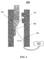
- FIGs. 3 and 4 illustrate an exemplary seat belt buckle 200.
- the seat belt buckle 200 includes the housing 102, the insertion member 104, the connector 106, and a switch 202.
- the seat belt buckle 200 can operate similarly to the seat belt buckle 100. That is, the insertion member 104 can cause the connector 106 to connect or disconnect from the switch 202. Connecting or disconnecting the connector 106 from the switch 202 can be used to determine whether the seat belt buckle 200 is fastened or unfastened (e.g., depending on whether the insertion member 104 descends into the cavity of the housing 102 upon fastening or unfastening).
- the switch 202 can also be a thick film polymer membrane switch.
- the switch 202 can include multiple layers.
- an upper layer of the switch 202 can be a flexible polymer film having a conductive ink screen printed thereon (e.g., to form conductive tracks).
- a middle layer of the switch 202 can be a polymer film that acts as a spacer to create an air gap.
- a lower layer of the switch 202 can also include a conductive ink track screen printed thereon.
- the lower layer of the membrane switch 202 can be an FR4 type PCB or can be a flexible polymer film such as, for example, polyester.
- the switch 202 When the switch 202 is open (e.g., when the connector 106 is not connected or coupled to the switch 202 as illustrated in FIG. 3 ), the switch 202 can provide a relatively high resistance. For example, the switch 202 can substantially operate as an open circuit, thereby providing an effective infinite resistance. When the switch 202 is closed (e.g., when the connector 106 is connected or coupled to the switch 202 as illustrated in FIG. 4 ), the switch 202 can provide a relatively low resistance. For example, the switch 202 can substantially operate as a short circuit, thereby providing an effectively negligible amount of resistance. Based on the operational state of the switch 202, i.e., whether the switch 202 provides an open or short circuit, a state of the seat belt buckle 200 can be determined. For example, it may be determined whether the seat belt buckle 200 is fastened or unfastened. An output of the switch 202 from which this determination can be made can be provided to additional components of the vehicle, as discussed above.
- FIGs. 5 and 6 illustrate an exemplary seat belt buckle 500.
- the seat belt buckle 500 can include a first housing portion 502, a second housing portion 504, an insertion member 104, a connector 506, an extension member 510, and a switch 508.
- the extension member 510 can be formed as part of the connector 506 or can be a separate component coupled thereto, as serves as the point of contact for the connector 506.
- the seat belt buckle 500 can operate similarly to seat belt buckles 100 and 200.
- the insertion member 104 can cause the connector 506 (e.g., by way of the extension member 510) to connect or disconnect from the switch 508 (i.e., to make contact or not make contact with the switch 508). Connecting or disconnecting the connector 506 from the switch 508 can be used to determine whether the seat belt buckle 500 is fastened or unfastened (e.g., depending on whether the insertion member 104 descends into or moves out of the cavity formed between the first housing portion 502 and the second housing portion 504 upon fastening or unfastening).
- the second housing portion 504 can be arranged to form a second cavity 512 adjacent a first cavity 505, wherein the first cavity 505 houses the insertion member 104.
- the switch 508 can be coupled or attached to an internal wall or portion within the chamber or cavity of the second housing portion 504 as shown in FIG. 5 .
- the connector 506 can be coupled or attached to an internal wall or portion 514 within the chamber or cavity of the second housing portion 504 facing away from the first housing portion 502, as shown in FIG. 5 .
- the connector 506 can protrude from or be positioned within the second cavity 512 of the second housing portion 504 and can extend into the first cavity 505 formed between the first housing portion 502 and the second housing portion 504.
- the connector 506 can make contact with the switch 508 by the extension member 510.
- the connector 506 can be bent or shaped such that it can be stabilized at one end 513 within the second cavity 512 of the second housing portion 504, and the connector 506 can be unattached at a second end 515.
- the connector 506 can be bent or shaped to make contact with the insertion member 104 along any portion of the connector 506 between the stabilized end 513 and the unattached end 515. Further, the unattached end 515 of the connector 506 can be bent, shaped or curled, for example as shown in FIG. 5 .
- movement of the insertion member 104 within the first cavity 505 formed between the first housing portion 502 and the second housing portion 504 can cause the connector 506 to discontinue contact (e.g., disconnect) with the switch 508.
- a portion 507 of the insertion member 104 is positioned outside of the first cavity 505 formed between the first housing portion 502 and the second housing portion 504. Because a substantial portion of the insertion member 104 is positioned outside of the first cavity 505, the insertion member 104 does not provide sufficient force on the connector 506 to cause the extension member 510 to move away from the switch 508. Consequently, the extension member 510 of the connector 506 makes contact with/presses down on the switch 508.
- the switch 508 can be configured to provide a relatively lower resistance (e.g., 100 Ohms or lower) as compared to the resistance provided by the switch 508 when the extension member 510 does not make contact with/does not press down on the switch 508 (e.g., when the switch 508 is open).
- a relatively lower resistance e.g. 100 Ohms or lower
- the insertion member 104 is positioned further inside of the cavity formed between the first housing portion 502 and the second housing portion 504. As a result, a force from the insertion member 104 is applied to the connector 506, which in turn moves the extension member 510 away from the switch 508. Therefore, the connector 506/extension member 510 no longer presses down/makes contact with the switch 508. Under this scenario, the switch 508 can be considered to be open.
- the switch 508 can provide a relatively higher resistance (e.g., 400 Ohms or higher) as compared to the resistance provided by the switch 508 when the switch 508 and the connector 506 come into contact (e.g., when the switch 508 is closed). Based on the operational state of the switch 508, i.e., whether the switch 508 provides relatively higher or lower resistance, a state of the seat belt buckle 500 can be determined, for example, whether the seat belt buckle 500 is fastened or unfastened.
- a relatively higher resistance e.g. 400 Ohms or higher
- a state of the seat belt buckle 500 can be determined, for example, whether the seat belt buckle 500 is fastened or unfastened.
- the seat belt buckle 500 can be configured to be fastened or unfastened, with the switch 508 providing either relatively higher resistance or relatively lower resistance.
- An output of the switch 508, from which this determination may be made, can be provided to additional components of a vehicle, for example as discussed above.
- the connector 506 may be a phosphor bronze spring operating as a cantilever.
- the extension member 510 may also be formed of phosphor bronze.
- the switch 508 can operate and/or be formed similarly to the switch 108.
- FIGs. 7 and 8 illustrate an exemplary seat belt buckle 700.
- the seat belt buckle 700 includes a first housing portion 702, a second housing portion 704, an insertion member 104, a connector 706, an extension member 710, and a switch 708.
- the seat belt buckle 700 can operate similarly to seat belt buckles 100, 200, and 500. That is, the insertion member 104 can cause the connector 706 to connect or disconnect from the switch 708 (i.e., to make contact or not make contact with the switch 708).
- Connecting or disconnecting the connector 706 from the switch 708 can be used to determine whether the seat belt buckle 700 is fastened or unfastened, for example, depending on whether the insertion member 104 descends into the cavity formed between the first housing portion 702 and the second housing portion 704 upon fastening or unfastening.
- the second housing portion 704 can be arranged to form a chamber or second cavity 712.
- the switch 708 can be coupled or attached to an internal wall or portion 716 within the chamber or second cavity 712 of the second housing portion 704 facing the first housing portion 702, as shown in FIG. 7 .
- the connector 706 can be coupled or attached to a bottom wall or portion 718 within the chamber or second cavity 712 of the second housing portion 704, as shown in FIG. 7 .
- the connector 706 can protrude from or be positioned within the second cavity 712 of the second housing portion 704 and extend into the cavity 705 formed between the first housing portion 702 and the second housing portion 704.
- the connector 706 can make contact with the switch 708 by the extension member 710.
- the connector 706 can be bent or shaped such that it can be stabilized at one end 713 within the second cavity 712 (e.g., bottom wall or portion 718) of the second housing portion 704 and can be unattached at a second end 715.
- the connector 706 can be bent or shaped to make contact with the insertion member 104 along any portion of the connector 706 between the stabilized end 713 and the unattached end 715.
- the unattached end 715 of the connector 706 can be bent, shaped or curled, for example as shown in FIG. 7 .
- the extension member 710 can be formed as part of the connector 706 or can be a separate component coupled thereto.
- a substantial portion of the insertion member 104 may be removed from within the cavity 705 formed between the first housing portion 702 and the second housing portion 704, which can, in turn, cause the extension member 710 and the connector 706 to discontinue contact with the switch 708. Conversely, the insertion member 104 can descend further into the cavity 705 formed between the first housing portion 702 and the second housing portion 704, and can cause the connector 706/extension member 710 to make contact or press down on the switch 708 (as illustrated in FIG. 8 ).
- the insertion member 104 does not does provide sufficient force to cause the connector 706 and the extension member 710 to move toward the switch 708.
- the switch 708 can be considered to be open.
- the switch 708, when open, can provide a relatively high resistance (e.g., infinity or effectively an open circuit).
- the insertion member 104 is positioned further inside of the cavity 705 formed between the first housing portion 702 and the second housing portion 704.
- the insertion member 104 can apply a force on the connector 706 that can cause the connector 706 and the extension member 710 to move toward and eventually make contact with/press down on the switch 708.
- the switch 708 can be considered to be closed.
- the switch 708, when closed, can provide a relatively lower resistance.
- the switch 708 can substantially operate as a short circuit, thereby providing an effectively negligible amount of resistance.
- a state of the seat belt buckle 700 can be determined, for example, whether the seat belt buckle 700 is fastened or unfastened.
- the seat belt buckle 700 can be configured to be fastened or unfastened with the switch 708 providing either relatively higher resistance (e.g., an open circuit) or relatively lower resistance (e.g., a short circuit).
- An output of the switch 708 from which this determination can be made can be provided to additional components of a vehicle as discussed above.
- the connector 706 can be a phosphor bronze spring and can operate as a cantilever.
- the extension member 710 can also be formed of phosphor bronze.
- the switch 708 can operate and/or be formed similarly to the switch 202.
- FIG. 9 illustrates an exemplary polymer membrane switch 900.
- the polymer membrane switch 900 can be representative of an embodiment of switches 108, 202, 508, and 708 described above.
- the polymer membrane switch 900 may include a first layer 902, a second layer 904, a conductor 910, and a resistive element 908.
- the first layer 902 (e.g., such as an upper layer) and the second layer 904 (e.g., such as a bottom layer) can each be formed from or made of a flexible polymer film.
- the second layer 904 can be made to be more rigid than the first layer 902 in certain embodiments.
- a gap or space 912 can be positioned between the first layer 902 and the second layer 904.
- the conductor 910 may include a first conductive element 910-A and a second conductive element 910-B, and may be positioned between the first layer 902 and the second layer 904.
- the conductor 910 may be one continuous conductor (such as, for example, a conductive metal) such that the first and second conductive elements 910A-B are integrally coupled.
- the conductor 910 can be coupled to the resistive element 908.
- the switch 900 can provide a relatively high resistance (e.g., approximately 400 Ohms or higher).
- the switch 900 can provide a relatively higher resistance in this state since any current through the conductor 910 must traverse the entirety of the resistive element 908.
- This relatively higher resistance provided by the switch 900 in this operational state can be provided between the terminal ends of the conductor 910 as shown in FIG. 9 .
- the circuit path provided by the conductor 910 is reduced. That is, the portion of the conductor 910 adjacent to the first layer 902 presses down and makes contact with the resistive element 908 and the portion of the conductor 910 adjacent to the second layer 904.
- the switch 900 can provide a relatively lower resistance in this state since any current through the conductor 910 must traverse a shorter circuit path and specifically traverses less than the entirety of the resistive element 908.
- the relatively lower resistance provided by the switch 900 in this operation state can be 100 Ohms or lower.
- This relatively lower resistance provided by the switch 900 in this operational state can be provided between the terminal ends of the conductor 910 as shown in FIG. 9 .
- the conductor 910 is squeezed down onto itself, thereby making a circuit path for a current that traverses less than the entire conductor 910 and the entire resistive element 908.
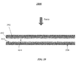
- FIG. 10 illustrates an exemplary polymer membrane switch 1000.
- the polymer membrane switch 1000 can be representative of an embodiment of the switches 108, 202, 508, and 708 described above.
- the polymer membrane switch 1000 may include a first layer 1002, a second layer 1004, a first conductor 1012, and a second conductor 1010.
- the first layer 1002 (e.g., such as an upper layer) and the second layer 1004 (e.g., such as a bottom layer) can be a made from or formed by a flexible polymer film.
- the second layer 1004 can be made to be more rigid than the first layer 1002 in certain embodiments.
- the first layer 1002 and the second layer 1004 may be separated such that a space or gap 1014 is positioned between the first layer 1002 and the second layer 1004.
- the first conductor 1010 can be positioned adjacent to the first layer 1002 (or attached or coupled thereto).
- the second conductor 1010 can be positioned adjacent to the second layer 1004 (or attached or coupled thereto).
- the switch can provide a relatively higher resistance (e.g., approximately infinite resistance or an open circuit).
- the switch 1000 can provide a relatively higher resistance in this state since no current can flow between the first and second conductors 1012 and 1010 (since the conductors 1012 and 1010 are not touching or in contact with one another).
- This relatively higher resistance provided by the switch 1000 in this operational state can be provided between the terminal ends of the conductor 1000, that is, a resistance as measured between the conductors 1012 and 1010 can effectively provide infinite resistance (since the conductors 1012 and 1010 form an open circuit when no in contact with one another).
- the switch 1000 When a force does act on the switch 1000, that is, when the first layer 1002 is pressed down toward the lower layer 1004, the switch can provide a relatively lower resistance (e.g., approximately zero resistance or a short circuit).
- the switch 1000 can provide a lower resistance in this state since the conductors 1012 and 1010 can be forced to come into contact with one another.
- a current can flow between the first and second conductors 1012 and 1010 with no resistance because there are no resistive elements formed by the circuit path of the first and second conductors 1012 and 1010 when they come into contact with one another.
- This relatively lower resistance provided by the switch 1000 in this operational state can be provided between the terminal ends of the conductor 1000, that is, a resistance as measured between the conductors 1012 and 1010 when the conductors are touching can effectively provide zero resistance because the conductors 1012 and 1010 form a short circuit.
- the conductor 910, the conductor 1012, and the conductor 1010 can be formed in relation to switches 108 and 202 as a conductive ink screen by directly forming a circuit on the surface of the respective layers using a technique such as a screen printing method after processing metal powder into an ink.
- FIGS. 11A-B illustrate another exemplary polymer membrane switch.
- an upper layer 1140 can be a flexible polymer film having a conductive ink screen printed thereon (e.g., to form conductive tracks).
- a middle layer 1142 of the switch 1108 can be a polymer film that acts as a spacer to create an air gap 1144.
- a lower layer 1148 of the switch 1108 can include conductive tracks and can also include a resistive element printed thereon.
- the switch 1108 is provided within a housing having a first housing portion 1102 and a second housing portion 1104.
- the conductive ink screen/track of the upper layer 1140 can come into contact with the resistive track of the lower layer 1148.
- This point of contact e.g., when the switch 1108 is closed
- the lower layer 1140 of the membrane switch 1108 can be an FR4 type PCB or can be a flexible polymer film such as, for example, polyester.
Landscapes
- Engineering & Computer Science (AREA)
- Mechanical Engineering (AREA)
- Automation & Control Theory (AREA)
- Automotive Seat Belt Assembly (AREA)
- Buckles (AREA)
Abstract
Description
- This application claims priority to
U.S. Provisional Patent Application No. 62/103,535, filed January 14, 2015 U.S. Provisional Patent Application No. 62/101,650, filed January 9, 2015 - This disclosure relates generally to the field of switches and more particularly to seat belt buckle switches.
- Vehicle restraint systems, also referred to as "seat belts", are used to secure an occupant within a vehicle. A common vehicle restraint system includes a lap belt and a shoulder belt. Typically, the lap belt and the shoulder belt are connected together at one end and include a latch plate. The other end of the shoulder belt and lap belt is connected to the vehicle structure. A safety seatbelt buckle configured to receive the latch plate is also connected to the vehicle structure. When the buckle and the latch plate are connected (e.g., across an occupant's shoulder and waist), the vehicle restraint system may operate to restrain movement of the occupant, e.g., during breaking or a collision.
- The buckle may identify whether a driver and/or an occupant wears the seatbelt. For this purpose, the buckle normally includes a mechanical switch such as a micro-switch that may be operated with a tongue of the belt. In one approach, the switch is actuated in response to the insertion or removal of the tongue, so that an indicator, e.g., on an instrument panel, is activated.
- Seat belt buckles can include switches or sensors that can be used to determine when a seat belt buckle is fastened or unfastened. Conventional seat belt buckle switches or sensors suffer from one or more problems including, for example, high manufacturing costs and/or high likelihoods of mechanical failure.
- This Summary is provided to introduce a selection of concepts in a simplified form that are further described below in the Detailed Description. This Summary is not intended to identify key features or essential features of the claimed subject matter, nor is it intended as an aid in determining the scope of the claimed subject matter.
- A need exists for an improved switch or sensor for a seat belt buckle that is durable with reduced installation complexity and lower costs. Approaches described herein provide an improved seat belt buckle switch.
- In one approach, an apparatus includes a housing having a cavity, an insertion member moveable within the cavity, a connector positioned within the cavity, and a switch positioned within the cavity, wherein movement of the insertion member causes the connector to connect or disconnect from the switch. In this approach, the switch includes a first conductive element formed adjacent a first layer of flexible film, and a second conductive element formed adjacent a second layer of flexible film, wherein the first and second layers of flexible film are separated by a gap.
- In another approach, an apparatus includes a housing having a first cavity and a second cavity, an insertion member moveable within the first cavity, a connector extending into the first cavity, and a switch positioned within the second cavity, wherein movement of the insertion member causes the connector to connect or disconnect from the switch. In this approach, the switch includes a first conductive element formed adjacent a first layer of flexible polymer film, and a second conductive element formed adjacent a second layer of flexible polymer film, wherein the first and second layers of flexible polymer film are separated by an air gap.
- In yet another approach, an apparatus includes a housing having a cavity, an insertion member moveable within the cavity, a connector positioned within the cavity; and a switch positioned within the cavity, wherein movement of the insertion member causes the connector to connect or disconnect from the switch. In this approach, the switch includes an upper layer of flexible film having a conductive element formed thereon, a lower layer of flexible film adjacent the upper layer of flexible film, and a middle spacer layer disposed between the upper and lower layers of flexible film, the middle spacer layer defining an air gap.
- By way of example, specific embodiments of the disclosed device will now be described, with reference to the accompanying drawings.
-
FIG. 1 illustrates an exemplary seat belt buckle switch in accordance with a first aspect of the present disclosure. -
FIG. 2 illustrates operation of the exemplary seat belt buckle switch depicted inFIG. 1 . -
FIG. 3 illustrates an exemplary seat belt buckle switch in accordance with a second aspect of the present disclosure. -
FIG. 4 illustrates operation of the exemplary seat belt buckle switch depicted inFIG. 3 . -
FIG. 5 illustrates an exemplary seat belt buckle switch in accordance with a third aspect of the present disclosure. -
FIG. 6 illustrates operation of the exemplary seat belt buckle switch depicted inFIG. 5 . -
FIG. 7 illustrates an exemplary seat belt buckle switch in accordance with a fourth aspect of the present disclosure. -
FIG. 8 illustrates operation of the exemplary seat belt buckle switch depicted inFIG. 7 . -
FIG. 9 illustrates an exemplary polymer membrane switch in accordance with the present disclosure. -
FIG. 10 illustrates an exemplary polymer membrane switch in accordance with a second aspect of the present disclosure. -
FIGS. 11A-B illustrate an exemplary polymer membrane switch in accordance with aspects of the present disclosure. - The drawings are not necessarily to scale. The drawings are merely representations, not intended to portray specific parameters of the disclosure. Furthermore, the drawings are intended to depict exemplary embodiments of the disclosure, and therefore is not considered as limiting in scope.
- An apparatus in accordance with the present disclosure will now be described more fully hereinafter with reference to the accompanying drawings, where embodiments of the methods are shown. The apparatus may be embodied in many different forms and are not to be construed as being limited to the embodiments set forth herein. Instead, these embodiments are provided so this disclosure will be thorough and complete, and will fully convey the scope of the system and method to those skilled in the art.
- For the sake of convenience and clarity, terms such as "top," "bottom," "upper," "lower," "vertical," "horizontal," "lateral," and "longitudinal" will be used herein to describe the relative placement and orientation of these components and their constituent parts with respect to the geometry and orientation of a component of a device as appearing in the figures. The terminology will include the words specifically mentioned, derivatives thereof, and words of similar meaning and/or significance.
- As used herein, an element or operation recited in the singular and proceeded with the word "a" or "an" is to be understood as including plural elements or operations, until such exclusion is explicitly recited. Furthermore, references to "one embodiment" of the present disclosure are not intended as limiting. Additional embodiments may also incorporating the recited features.
-
FIG. 1 illustrates an exemplaryseat belt buckle 100. As shown, theseat belt buckle 100 includes ahousing 102 and aninsertion member 104. Thehousing 102 can include one or more portions 103A-B arranged to form a chamber orcavity 105 for accepting theinsertion member 104. Thehousing 102 can be formed of a carrier molding in some non-limiting embodiments. Anend portion 107 of theinsertion member 104 can be a tongue portion dimensioned to fit within thecavity 105 provided by thehousing 102. Theinsertion member 104 can move within thecavity 105 of thehousing 102 during latching/unlatching of theseat belt buckle 100. - As further shown in
FIG. 1 , theseat belt buckle 100 can include aconnector 106 and aswitch 108. Theconnector 106 can be a spring such as, for example, a phosphor bronze spring. Theconnector 106 can be coupled or attached to aninternal wall 109 or fastener portion 111 of thehousing 102. - The
connector 106 may protrude or be positioned within thecavity 105 of thehousing 102 such that movement of theinsertion member 104 within thecavity 105 can cause an end of theconnector 106 to come into contact with theswitch 108. That is, movement of theinsertion member 104 can cause movement of theconnector 106 such that theconnector 106 can be actuated, e.g., connected or disconnected from theswitch 108. Theconnector 106 may be bent or shaped such that it can be stabilized at oneend 113 and unattached at asecond end 115. Furthermore, theconnector 106 can be bent or have an arcuate shape for making contact with theinsertion member 104 along any portion of theconnector 106 between the stabilizedend 113 and theunattached end 115. Further, theunattached end 115 of theconnector 106 can be bent, shaped or curled, for example as shown inFIG. 1 . As will be appreciated, theconnector 106 may take on any number of shapes/geometries. - In some embodiments, the
insertion member 104 can be configured to move further into thecavity 105 of thehousing 102 during latching or unlatching of theseat belt buckle 100. That is, theinsertion member 104 can be configured to cause theconnector 106 to come into contact with theswitch 108 when theseat belt buckle 100 is either fastened or unfastened. Under either scenario, contact between theswitch 108 and theconnector 106 can signal whether or not theseat belt buckle 100 is latched or unlatched as appropriate. - In
FIG. 1 , aforce 120 resulting from theinsertion member 104 is removed from theconnector 106, e.g., when theseat belt buckle 100 is unfastened, such that theconnector 106 is not in contact with theswitch 108. Under this scenario, theswitch 108 can provide a relatively higher resistance (e.g., 400 Ohms or higher) as compared to the resistance provided by theswitch 108 when theswitch 108 and theconnector 106 come into contact. -
FIG. 2 illustrates theseat belt buckle 100 with theconnector 106 in contact with theswitch 108. As shown inFIG. 2 , theinsertion member 104 is positioned further inside of thecavity 105 of thehousing 102. As a result, aforce 118 from theinsertion member 104 can be sufficient for applying acorresponding force 120 that causes theconnector 106 to make contact with theswitch 108. Under this scenario, theswitch 108 can provide a relatively lower resistance (e.g., 100 Ohms or lower) as compared to the resistance provided by theswitch 108 when theswitch 108 and theconnector 106 are not in contact (e.g., as shown inFIG. 1 ). - In some embodiments, the
switch 108 may be a thick film polymer membrane switch. Theswitch 108 can be used to detect or determine when theseat belt buckle 100 is fastened (e.g., latched) or unfastened (e.g., unlatched). An output of theswitch 108 can be provided to one or more components of avehicle system 124. For example, anoutput 128 of theswitch 108, which may signal when theseat belt buckle 100 is latched or unlatched, can be provided to anairbag deployment system 130 of avehicle 132 and/or can be used to adjust operation of warning lights, alarms, and/or sounds of thevehicle 132. - The
switch 108 can be comprised of multiple layers. As an example, an upper layer can be a flexible polymer film having a conductive ink screen printed thereon (e.g., to form conductive tracks). A middle layer of theswitch 108 can be a polymer film that acts as a spacer to create an air gap. A lower layer of theswitch 108 can include conductive tracks and can also include a resistive element printed thereon. - When a force acts on the upper layer of the switch 108 (e.g., when the
connector 106 presses down onto the switch 108), the conductive ink screen/track of the upper layer can come into contact with the resistive track of the lower layer. This point of contact (e.g., when theswitch 108 is closed) can be configured to provide a relatively lower resistance (e.g., 100 Ohms or lower) as compared to the resistance (e.g., 400 Ohms or higher) provided when the upper layer and lower layer of theswitch 108 are not in contact (e.g., when theswitch 108 is open). The lower layer of themembrane switch 108 can be an FR4 type PCB or can be a flexible polymer film such as, for example, polyester. - In some embodiments, FR4 (or FR-4) is a grade designation assigned to glass-reinforced epoxy laminate sheets, tubes, rods and PCBs, wherein "FR" stands for flame retardant, and denotes that safety of flammability of FR-4 is in compliance with the standard UL94V-0. FR4 is a composite material composed of woven fiberglass cloth with an epoxy resin binder that is flame resistant (e.g., self-extinguishing). FR4 may be created from the constituent materials epoxy resin, woven glass fabric reinforcement, brominated flame retardant, etc.
-
FIGs. 3 and4 illustrate an exemplaryseat belt buckle 200. As shown inFIGs. 3 and4 , theseat belt buckle 200 includes thehousing 102, theinsertion member 104, theconnector 106, and aswitch 202. Theseat belt buckle 200 can operate similarly to theseat belt buckle 100. That is, theinsertion member 104 can cause theconnector 106 to connect or disconnect from theswitch 202. Connecting or disconnecting theconnector 106 from theswitch 202 can be used to determine whether theseat belt buckle 200 is fastened or unfastened (e.g., depending on whether theinsertion member 104 descends into the cavity of thehousing 102 upon fastening or unfastening). - The
switch 202 can also be a thick film polymer membrane switch. Theswitch 202 can include multiple layers. As an example, an upper layer of theswitch 202 can be a flexible polymer film having a conductive ink screen printed thereon (e.g., to form conductive tracks). A middle layer of theswitch 202 can be a polymer film that acts as a spacer to create an air gap. A lower layer of theswitch 202 can also include a conductive ink track screen printed thereon. The lower layer of themembrane switch 202 can be an FR4 type PCB or can be a flexible polymer film such as, for example, polyester. - When the
switch 202 is open (e.g., when theconnector 106 is not connected or coupled to theswitch 202 as illustrated inFIG. 3 ), theswitch 202 can provide a relatively high resistance. For example, theswitch 202 can substantially operate as an open circuit, thereby providing an effective infinite resistance. When theswitch 202 is closed (e.g., when theconnector 106 is connected or coupled to theswitch 202 as illustrated inFIG. 4 ), theswitch 202 can provide a relatively low resistance. For example, theswitch 202 can substantially operate as a short circuit, thereby providing an effectively negligible amount of resistance. Based on the operational state of theswitch 202, i.e., whether theswitch 202 provides an open or short circuit, a state of theseat belt buckle 200 can be determined. For example, it may be determined whether theseat belt buckle 200 is fastened or unfastened. An output of theswitch 202 from which this determination can be made can be provided to additional components of the vehicle, as discussed above. -
FIGs. 5 and6 illustrate an exemplaryseat belt buckle 500. As shown inFIGs. 5 and6 , theseat belt buckle 500 can include afirst housing portion 502, asecond housing portion 504, aninsertion member 104, aconnector 506, anextension member 510, and aswitch 508. Theextension member 510 can be formed as part of theconnector 506 or can be a separate component coupled thereto, as serves as the point of contact for theconnector 506. - The
seat belt buckle 500 can operate similarly to seat belt buckles 100 and 200. In some embodiments, theinsertion member 104 can cause the connector 506 (e.g., by way of the extension member 510) to connect or disconnect from the switch 508 (i.e., to make contact or not make contact with the switch 508). Connecting or disconnecting theconnector 506 from theswitch 508 can be used to determine whether theseat belt buckle 500 is fastened or unfastened (e.g., depending on whether theinsertion member 104 descends into or moves out of the cavity formed between thefirst housing portion 502 and thesecond housing portion 504 upon fastening or unfastening). - As further shown in
FIG. 5 , thesecond housing portion 504 can be arranged to form asecond cavity 512 adjacent afirst cavity 505, wherein thefirst cavity 505 houses theinsertion member 104. Theswitch 508 can be coupled or attached to an internal wall or portion within the chamber or cavity of thesecond housing portion 504 as shown inFIG. 5 . Theconnector 506 can be coupled or attached to an internal wall orportion 514 within the chamber or cavity of thesecond housing portion 504 facing away from thefirst housing portion 502, as shown inFIG. 5 . Theconnector 506 can protrude from or be positioned within thesecond cavity 512 of thesecond housing portion 504 and can extend into thefirst cavity 505 formed between thefirst housing portion 502 and thesecond housing portion 504. Theconnector 506 can make contact with theswitch 508 by theextension member 510. In some embodiments, theconnector 506 can be bent or shaped such that it can be stabilized at oneend 513 within thesecond cavity 512 of thesecond housing portion 504, and theconnector 506 can be unattached at asecond end 515. Theconnector 506 can be bent or shaped to make contact with theinsertion member 104 along any portion of theconnector 506 between the stabilizedend 513 and theunattached end 515. Further, theunattached end 515 of theconnector 506 can be bent, shaped or curled, for example as shown inFIG. 5 . - As further shown in
FIGs. 5 and6 , movement of theinsertion member 104 within thefirst cavity 505 formed between thefirst housing portion 502 and thesecond housing portion 504 can cause theconnector 506 to discontinue contact (e.g., disconnect) with theswitch 508. As shown inFIG. 5 , aportion 507 of theinsertion member 104 is positioned outside of thefirst cavity 505 formed between thefirst housing portion 502 and thesecond housing portion 504. Because a substantial portion of theinsertion member 104 is positioned outside of thefirst cavity 505, theinsertion member 104 does not provide sufficient force on theconnector 506 to cause theextension member 510 to move away from theswitch 508. Consequently, theextension member 510 of theconnector 506 makes contact with/presses down on theswitch 508. When theextension member 510 makes contact with/presses down on the switch 508 (e.g., when theswitch 508 is closed), theswitch 508 can be configured to provide a relatively lower resistance (e.g., 100 Ohms or lower) as compared to the resistance provided by theswitch 508 when theextension member 510 does not make contact with/does not press down on the switch 508 (e.g., when theswitch 508 is open). - As shown in
FIG. 6 , theinsertion member 104 is positioned further inside of the cavity formed between thefirst housing portion 502 and thesecond housing portion 504. As a result, a force from theinsertion member 104 is applied to theconnector 506, which in turn moves theextension member 510 away from theswitch 508. Therefore, theconnector 506/extension member 510 no longer presses down/makes contact with theswitch 508. Under this scenario, theswitch 508 can be considered to be open. When theextension member 510/connector 506 is no longer in contact with theswitch 508, theswitch 508 can provide a relatively higher resistance (e.g., 400 Ohms or higher) as compared to the resistance provided by theswitch 508 when theswitch 508 and theconnector 506 come into contact (e.g., when theswitch 508 is closed). Based on the operational state of theswitch 508, i.e., whether theswitch 508 provides relatively higher or lower resistance, a state of theseat belt buckle 500 can be determined, for example, whether theseat belt buckle 500 is fastened or unfastened. - Further, the
seat belt buckle 500 can be configured to be fastened or unfastened, with theswitch 508 providing either relatively higher resistance or relatively lower resistance. An output of theswitch 508, from which this determination may be made, can be provided to additional components of a vehicle, for example as discussed above. As with theconnector 106 described above, theconnector 506 may be a phosphor bronze spring operating as a cantilever. Theextension member 510 may also be formed of phosphor bronze. Theswitch 508 can operate and/or be formed similarly to theswitch 108. -
FIGs. 7 and8 illustrate an exemplaryseat belt buckle 700. As shown inFIGs. 7 and8 , theseat belt buckle 700 includes afirst housing portion 702, asecond housing portion 704, aninsertion member 104, aconnector 706, anextension member 710, and aswitch 708. Theseat belt buckle 700 can operate similarly to seat belt buckles 100, 200, and 500. That is, theinsertion member 104 can cause theconnector 706 to connect or disconnect from the switch 708 (i.e., to make contact or not make contact with the switch 708). Connecting or disconnecting theconnector 706 from the switch 708 (e.g., by way of the extension member 710) can be used to determine whether theseat belt buckle 700 is fastened or unfastened, for example, depending on whether theinsertion member 104 descends into the cavity formed between thefirst housing portion 702 and thesecond housing portion 704 upon fastening or unfastening. - As further shown in
FIG. 7 , thesecond housing portion 704 can be arranged to form a chamber orsecond cavity 712. Theswitch 708 can be coupled or attached to an internal wall orportion 716 within the chamber orsecond cavity 712 of thesecond housing portion 704 facing thefirst housing portion 702, as shown inFIG. 7 . Theconnector 706 can be coupled or attached to a bottom wall orportion 718 within the chamber orsecond cavity 712 of thesecond housing portion 704, as shown inFIG. 7 . Theconnector 706 can protrude from or be positioned within thesecond cavity 712 of thesecond housing portion 704 and extend into thecavity 705 formed between thefirst housing portion 702 and thesecond housing portion 704. Theconnector 706 can make contact with theswitch 708 by theextension member 710. - In some embodiments, the
connector 706 can be bent or shaped such that it can be stabilized at oneend 713 within the second cavity 712 (e.g., bottom wall or portion 718) of thesecond housing portion 704 and can be unattached at asecond end 715. Theconnector 706 can be bent or shaped to make contact with theinsertion member 104 along any portion of theconnector 706 between the stabilizedend 713 and theunattached end 715. Further, theunattached end 715 of theconnector 706 can be bent, shaped or curled, for example as shown inFIG. 7 . Theextension member 710 can be formed as part of theconnector 706 or can be a separate component coupled thereto. - As further shown in
FIGs. 7 and8 , a substantial portion of theinsertion member 104 may be removed from within thecavity 705 formed between thefirst housing portion 702 and thesecond housing portion 704, which can, in turn, cause theextension member 710 and theconnector 706 to discontinue contact with theswitch 708. Conversely, theinsertion member 104 can descend further into thecavity 705 formed between thefirst housing portion 702 and thesecond housing portion 704, and can cause theconnector 706/extension member 710 to make contact or press down on the switch 708 (as illustrated inFIG. 8 ). - As shown in
FIG. 7 , theinsertion member 104 does not does provide sufficient force to cause theconnector 706 and theextension member 710 to move toward theswitch 708. Under this scenario, when theconnector 706/extension member 710 does not make contact with/press down on theswitch 708, theswitch 708 can be considered to be open. Theswitch 708, when open, can provide a relatively high resistance (e.g., infinity or effectively an open circuit). - As shown in
FIG. 8 , theinsertion member 104 is positioned further inside of thecavity 705 formed between thefirst housing portion 702 and thesecond housing portion 704. As a result, theinsertion member 104 can apply a force on theconnector 706 that can cause theconnector 706 and theextension member 710 to move toward and eventually make contact with/press down on theswitch 708. Under this scenario, when theconnector 706/extension member 710 makes contact with/presses down on theswitch 708, theswitch 708 can be considered to be closed. Theswitch 708, when closed, can provide a relatively lower resistance. As an example, theswitch 708 can substantially operate as a short circuit, thereby providing an effectively negligible amount of resistance. Based on the operational state of theswitch 708, i.e., whether theswitch 708 provides an open or short circuit, a state of theseat belt buckle 700 can be determined, for example, whether theseat belt buckle 700 is fastened or unfastened. - In some embodiments, the
seat belt buckle 700 can be configured to be fastened or unfastened with theswitch 708 providing either relatively higher resistance (e.g., an open circuit) or relatively lower resistance (e.g., a short circuit). An output of theswitch 708 from which this determination can be made can be provided to additional components of a vehicle as discussed above. As with theconnector 106 described above, theconnector 706 can be a phosphor bronze spring and can operate as a cantilever. Theextension member 710 can also be formed of phosphor bronze. Theswitch 708 can operate and/or be formed similarly to theswitch 202. -
FIG. 9 illustrates an exemplarypolymer membrane switch 900. Thepolymer membrane switch 900 can be representative of an embodiment ofswitches polymer membrane switch 900 may include afirst layer 902, asecond layer 904, aconductor 910, and aresistive element 908. - The first layer 902 (e.g., such as an upper layer) and the second layer 904 (e.g., such as a bottom layer) can each be formed from or made of a flexible polymer film. The
second layer 904 can be made to be more rigid than thefirst layer 902 in certain embodiments. A gap orspace 912 can be positioned between thefirst layer 902 and thesecond layer 904. Theconductor 910 may include a first conductive element 910-A and a second conductive element 910-B, and may be positioned between thefirst layer 902 and thesecond layer 904. Theconductor 910 may be one continuous conductor (such as, for example, a conductive metal) such that the first and second conductive elements 910A-B are integrally coupled. Theconductor 910 can be coupled to theresistive element 908. - When no force acts on the
switch 900, that is, when thefirst layer 902 is not pressed down toward thelower layer 904, theswitch 900 can provide a relatively high resistance (e.g., approximately 400 Ohms or higher). Theswitch 900 can provide a relatively higher resistance in this state since any current through theconductor 910 must traverse the entirety of theresistive element 908. This relatively higher resistance provided by theswitch 900 in this operational state can be provided between the terminal ends of theconductor 910 as shown inFIG. 9 . - When a force acts on the
first layer 902 of the switch 900 (e.g., when a connector such as theconnector 106 or theconnector 506/extension member 510 presses down on the first layer 902), the circuit path provided by theconductor 910 is reduced. That is, the portion of theconductor 910 adjacent to thefirst layer 902 presses down and makes contact with theresistive element 908 and the portion of theconductor 910 adjacent to thesecond layer 904. Theswitch 900 can provide a relatively lower resistance in this state since any current through theconductor 910 must traverse a shorter circuit path and specifically traverses less than the entirety of theresistive element 908. The relatively lower resistance provided by theswitch 900 in this operation state can be 100 Ohms or lower. This relatively lower resistance provided by theswitch 900 in this operational state can be provided between the terminal ends of theconductor 910 as shown inFIG. 9 . In effect, theconductor 910 is squeezed down onto itself, thereby making a circuit path for a current that traverses less than theentire conductor 910 and the entireresistive element 908. -
FIG. 10 illustrates an exemplarypolymer membrane switch 1000. Thepolymer membrane switch 1000 can be representative of an embodiment of theswitches polymer membrane switch 1000 may include afirst layer 1002, asecond layer 1004, afirst conductor 1012, and asecond conductor 1010. - The first layer 1002 (e.g., such as an upper layer) and the second layer 1004 (e.g., such as a bottom layer) can be a made from or formed by a flexible polymer film. The
second layer 1004 can be made to be more rigid than thefirst layer 1002 in certain embodiments. Thefirst layer 1002 and thesecond layer 1004 may be separated such that a space orgap 1014 is positioned between thefirst layer 1002 and thesecond layer 1004. Thefirst conductor 1010 can be positioned adjacent to the first layer 1002 (or attached or coupled thereto). Thesecond conductor 1010 can be positioned adjacent to the second layer 1004 (or attached or coupled thereto). - When no force acts on the
switch 1000, that is, when thefirst layer 1002 is not pressed down toward thelower layer 1004, the switch can provide a relatively higher resistance (e.g., approximately infinite resistance or an open circuit). Theswitch 1000 can provide a relatively higher resistance in this state since no current can flow between the first andsecond conductors 1012 and 1010 (since theconductors switch 1000 in this operational state can be provided between the terminal ends of theconductor 1000, that is, a resistance as measured between theconductors conductors - When a force does act on the
switch 1000, that is, when thefirst layer 1002 is pressed down toward thelower layer 1004, the switch can provide a relatively lower resistance (e.g., approximately zero resistance or a short circuit). Theswitch 1000 can provide a lower resistance in this state since theconductors second conductors second conductors switch 1000 in this operational state can be provided between the terminal ends of theconductor 1000, that is, a resistance as measured between theconductors conductors - The
conductor 910, theconductor 1012, and theconductor 1010 can be formed in relation toswitches -
FIGS. 11A-B illustrate another exemplary polymer membrane switch. For example, as shown, anupper layer 1140 can be a flexible polymer film having a conductive ink screen printed thereon (e.g., to form conductive tracks). Amiddle layer 1142 of theswitch 1108 can be a polymer film that acts as a spacer to create anair gap 1144. Alower layer 1148 of theswitch 1108 can include conductive tracks and can also include a resistive element printed thereon. Theswitch 1108 is provided within a housing having afirst housing portion 1102 and asecond housing portion 1104. - During use, when a force acts on the upper layer of the switch 1108 (e.g., when the
connector 1106 presses down onto the switch 1108), the conductive ink screen/track of theupper layer 1140 can come into contact with the resistive track of thelower layer 1148. This point of contact (e.g., when theswitch 1108 is closed) can be configured to provide a relatively lower resistance (e.g., 100 Ohms or lower) as compared to the resistance (e.g., 400 Ohms or higher) provided when theupper layer 1140 andlower layer 1148 of theswitch 1108 are not in contact (e.g., when theswitch 1108 is open). Thelower layer 1140 of themembrane switch 1108 can be an FR4 type PCB or can be a flexible polymer film such as, for example, polyester. - While the present disclosure has been disclosed with reference to certain embodiments, numerous modifications, alterations and changes to the described embodiments are possible without departing from the sphere and scope of the present disclosure.
Claims (20)
- An apparatus, comprising:a housing having a cavity;
an insertion member moveable within the cavity;
a connector positioned within the cavity; anda switch positioned within the cavity, wherein movement of the insertion member causes the connector to connect or disconnect from the switch, wherein the switch comprises:a first conductive element formed adjacent a first layer of flexible film; anda second conductive element formed adjacent a second layer of flexible film, wherein the first and second layers of flexible film are separated by a gap. - The apparatus of claim 1, wherein the second layer of flexible film includes a resistive element printed thereon.
- The apparatus of claim 1, wherein the second layer of flexible film is formed from a printed circuit board (PCB).
- The apparatus of claim 1, wherein the first and second layers of flexible film are formed from a flexible polymer.
- The apparatus of claim 1, wherein the switch further comprises a middle layer of flexible film disposed between the first and second layers of flexible film, the middle layer of flexible film arranged as a spacer to create an air gap.
- The apparatus of claim 1, wherein the connector is a spring.
- The apparatus of claim 6, wherein the spring is a phosphor bronze spring coupled to an internal wall or a fastener portion of the housing.
- The apparatus of claim 1, wherein the connector is connected to the switch when the insertion member is moved into the cavity toward to the switch.
- The apparatus of claim 1, wherein the connector is disconnected from the switch when the insertion member is moved away from the switch.
- The apparatus of claim 1, further comprising a second cavity defined by the housing.
- The apparatus of claim 10, wherein the connector extends from the second cavity into the cavity.
- The apparatus of claim 10, wherein the connector is coupled to the housing within the second cavity.
- The apparatus of claim 1, wherein the first conductive element and the second conductive element are integrally connected.
- The apparatus of claim 1, wherein an output of the switch is provided to a component of a vehicle.
- An apparatus, comprising:a housing having a first cavity and a second cavity;an insertion member moveable within the first cavity;a connector extending into the first cavity; anda switch positioned within the second cavity, wherein movement of the insertion member causes the connector to connect or disconnect from the switch, wherein the switch comprises:a first conductive element formed adjacent a first layer of flexible polymer film; anda second conductive element formed adjacent a second layer of flexible polymer film, wherein the first and second layers of flexible polymer film are separated by an air gap.
- The apparatus of claim 15, wherein the second layer of flexible polymer film includes a resistive element formed thereon.
- The apparatus of claim 15, wherein the second layer of flexible polymer film is formed from a printed circuit board (PCB).
- The apparatus of claim 15, wherein the switch further comprises a middle layer of flexible film disposed between the first and second layers of flexible film, the middle layer of flexible film arranged as a spacer to create the air gap.
- The apparatus of claim 15, wherein the first conductive element and the second conductive element are integrally connected.
- An apparatus, comprising:a housing having a cavity;an insertion member moveable within the cavity;a connector positioned within the cavity; anda switch positioned within the cavity, wherein movement of the insertion member causes the connector to connect or disconnect from the switch, wherein the switch comprises:an upper layer of flexible film having a conductive element formed thereon;a lower layer of flexible film adjacent the upper layer of flexible film; anda middle spacer layer disposed between the upper and lower layers of flexible film, the middle spacer layer defining an air gap.
Applications Claiming Priority (3)
| Application Number | Priority Date | Filing Date | Title |
|---|---|---|---|
| US201562101650P | 2015-01-09 | 2015-01-09 | |
| US201562103535P | 2015-01-14 | 2015-01-14 | |
| US14/988,837 US9821762B2 (en) | 2015-01-09 | 2016-01-06 | Seat belt buckle |
Publications (2)
| Publication Number | Publication Date |
|---|---|
| EP3042807A1 true EP3042807A1 (en) | 2016-07-13 |
| EP3042807B1 EP3042807B1 (en) | 2019-04-17 |
Family
ID=55072564
Family Applications (1)
| Application Number | Title | Priority Date | Filing Date |
|---|---|---|---|
| EP16150458.4A Active EP3042807B1 (en) | 2015-01-09 | 2016-01-07 | Seat belt buckle |
Country Status (5)
| Country | Link |
|---|---|
| US (1) | US9821762B2 (en) |
| EP (1) | EP3042807B1 (en) |
| JP (1) | JP6694272B2 (en) |
| KR (1) | KR102130136B1 (en) |
| CN (1) | CN105774747B (en) |
Cited By (1)
| Publication number | Priority date | Publication date | Assignee | Title |
|---|---|---|---|---|
| EP3385129A1 (en) * | 2017-04-05 | 2018-10-10 | Jörg Beutler | Closing device |
Families Citing this family (6)
| Publication number | Priority date | Publication date | Assignee | Title |
|---|---|---|---|---|
| CN107054285B (en) * | 2017-01-21 | 2018-12-25 | 绍兴职业技术学院 | Automobile assists the bindiny mechanism of preceding link block and rear link block in eye-splice |
| EP4000732B1 (en) * | 2020-11-16 | 2024-10-09 | Tecan Trading Ag | Robotic arm of an automated pipetting system |
| CN113012881A (en) * | 2021-03-01 | 2021-06-22 | 驭芯科技(上海)有限公司 | Method for assembling chip resistor on metal wire frame for mechanical switch type safety belt alarm sensor |
| CN113035479A (en) * | 2021-03-01 | 2021-06-25 | 驭芯科技(上海)有限公司 | Method for assembling chip resistor on metal wire frame and carrying out low-voltage packaging for mechanical switch type safety belt alarm sensor |
| KR102544014B1 (en) * | 2021-10-18 | 2023-06-15 | 엠피아주식회사 | Wear sensing monitoring system for vehicle seat belt |
| CN116439475A (en) * | 2022-01-07 | 2023-07-18 | 明门瑞士股份有限公司 | Fastening indicating device for fastener |
Citations (5)
| Publication number | Priority date | Publication date | Assignee | Title |
|---|---|---|---|---|
| GB2133625A (en) * | 1982-12-15 | 1984-07-25 | Spiralux Ltd | Electrical switch |
| GB2326978A (en) * | 1997-07-01 | 1999-01-06 | Autoliv Dev | A switch |
| US5970587A (en) * | 1997-12-11 | 1999-10-26 | Autoliv Development Ab | Seat belt buckle |
| US20050146420A1 (en) * | 2002-03-19 | 2005-07-07 | Bernd Ebert | Actuator for a belt latch mechanism |
| US20120188070A1 (en) * | 2011-01-24 | 2012-07-26 | Polycontact Ag | Circuit arrangement for a belt lock |
Family Cites Families (12)
| Publication number | Priority date | Publication date | Assignee | Title |
|---|---|---|---|---|
| US4163128A (en) * | 1977-09-19 | 1979-07-31 | Gateway Industries, Inc. | Safety buckle with switch |
| JPS5790527U (en) * | 1980-11-26 | 1982-06-03 | ||
| US5590904A (en) * | 1995-08-15 | 1997-01-07 | Trw Vehicle Safety Systems Inc. | Dual resistance switch for buckle confirmation |
| US7296825B1 (en) * | 1999-05-11 | 2007-11-20 | Autoliv Asp, Inc. | Multiple output buckle switch |
| JP2003317173A (en) * | 2002-04-23 | 2003-11-07 | Matsushita Electric Works Ltd | Crime prevention system |
| JP2005134941A (en) * | 2003-10-28 | 2005-05-26 | Matsushita Electric Works Ltd | Travel support system for emergency vehicle |
| JP2006248285A (en) * | 2005-03-08 | 2006-09-21 | Takata Corp | Seat belt device |
| DE102006050239A1 (en) * | 2006-10-18 | 2008-04-24 | Prettl, Rolf | Seat belt buckle switch for seat belts |
| JP2010272495A (en) * | 2009-05-20 | 2010-12-02 | Land Co Ltd | A street light that has a security camera and an outlet for charging a mobile phone, and whose lighting changes depending on the time of day and the movement of people. |
| JP2011040639A (en) * | 2009-08-14 | 2011-02-24 | Keiichi Shinoda | Opening/closing type solar panel streetlight |
| JP5787418B2 (en) * | 2013-05-30 | 2015-09-30 | 古野電気株式会社 | Wireless access point device, wireless network system, and wireless access point device control method |
| JP3196024U (en) * | 2014-11-13 | 2015-02-19 | 大日本印刷株式会社 | Display device |
-
2016
- 2016-01-06 US US14/988,837 patent/US9821762B2/en not_active Expired - Fee Related
- 2016-01-07 EP EP16150458.4A patent/EP3042807B1/en active Active
- 2016-01-08 KR KR1020160002492A patent/KR102130136B1/en not_active Expired - Fee Related
- 2016-01-08 JP JP2016002421A patent/JP6694272B2/en not_active Expired - Fee Related
- 2016-01-11 CN CN201610149687.4A patent/CN105774747B/en not_active Expired - Fee Related
Patent Citations (5)
| Publication number | Priority date | Publication date | Assignee | Title |
|---|---|---|---|---|
| GB2133625A (en) * | 1982-12-15 | 1984-07-25 | Spiralux Ltd | Electrical switch |
| GB2326978A (en) * | 1997-07-01 | 1999-01-06 | Autoliv Dev | A switch |
| US5970587A (en) * | 1997-12-11 | 1999-10-26 | Autoliv Development Ab | Seat belt buckle |
| US20050146420A1 (en) * | 2002-03-19 | 2005-07-07 | Bernd Ebert | Actuator for a belt latch mechanism |
| US20120188070A1 (en) * | 2011-01-24 | 2012-07-26 | Polycontact Ag | Circuit arrangement for a belt lock |
Cited By (4)
| Publication number | Priority date | Publication date | Assignee | Title |
|---|---|---|---|---|
| EP3385129A1 (en) * | 2017-04-05 | 2018-10-10 | Jörg Beutler | Closing device |
| CN108688613A (en) * | 2017-04-05 | 2018-10-23 | 博特勒·耶尔格 | locking device |
| US10709209B2 (en) | 2017-04-05 | 2020-07-14 | Joerg Beutler | Closure device |
| CN108688613B (en) * | 2017-04-05 | 2022-07-19 | 博特勒·耶尔格 | locking device |
Also Published As
| Publication number | Publication date |
|---|---|
| US9821762B2 (en) | 2017-11-21 |
| CN105774747B (en) | 2020-02-07 |
| JP6694272B2 (en) | 2020-05-13 |
| US20160200290A1 (en) | 2016-07-14 |
| JP2016128317A (en) | 2016-07-14 |
| KR102130136B1 (en) | 2020-07-03 |
| KR20160086289A (en) | 2016-07-19 |
| EP3042807B1 (en) | 2019-04-17 |
| CN105774747A (en) | 2016-07-20 |
Similar Documents
| Publication | Publication Date | Title |
|---|---|---|
| EP3042807B1 (en) | Seat belt buckle | |
| JP6283126B2 (en) | Load detection sensor unit | |
| EP3116075B1 (en) | Electrical plug connector for a safety restraint system | |
| US20120258620A1 (en) | Electrical connector configured to connect to a flex cable | |
| EP1844973A1 (en) | Noise reduction for flexible sensor material in occupant detection | |
| EP2034299A1 (en) | Excrement-detecting sensor | |
| DE102012208466A1 (en) | Buckle with a condition sensor for detecting the locking state of a safety belt system | |
| EP2696440A1 (en) | Connector | |
| DE102007039234B4 (en) | seat sensor | |
| KR20220087565A (en) | buckle | |
| CN102405505A (en) | Seat occupancy sensor | |
| DE202018000956U1 (en) | Pressure sensing device for a motor vehicle | |
| JP6148092B2 (en) | Membrane switch, sensor unit and seat device | |
| CN202903204U (en) | A sensor used for detecting a rapidly-decelerating/accelerating event | |
| JP6111166B2 (en) | Operation panel and method for manufacturing the operation panel | |
| JP2001260817A (en) | Device and method for detecting mounting condition of seatbelt | |
| DE202013010948U1 (en) | Unit for seat occupancy recognition of a vehicle seat | |
| JP2008003095A (en) | Pressure sensitive switch | |
| US20030205886A1 (en) | Airbag door with an electromagnetic field | |
| DE112019005087T5 (en) | ACCELERATION SENSOR | |
| CN114729843A (en) | Vehicle mounted object detection device and vehicle control system | |
| CN103213560A (en) | Safety belt buckle sensor | |
| DE102019113893A1 (en) | Seat belt | |
| WO2019014363A1 (en) | Occupant detection system, sensing mat and electrical switch | |
| EP2905587B1 (en) | Occupant detection device |
Legal Events
| Date | Code | Title | Description |
|---|---|---|---|
| PUAI | Public reference made under article 153(3) epc to a published international application that has entered the european phase |
Free format text: ORIGINAL CODE: 0009012 |
|
| AK | Designated contracting states |
Kind code of ref document: A1 Designated state(s): AL AT BE BG CH CY CZ DE DK EE ES FI FR GB GR HR HU IE IS IT LI LT LU LV MC MK MT NL NO PL PT RO RS SE SI SK SM TR |
|
| AX | Request for extension of the european patent |
Extension state: BA ME |
|
| STAA | Information on the status of an ep patent application or granted ep patent |
Free format text: STATUS: REQUEST FOR EXAMINATION WAS MADE |
|
| 17P | Request for examination filed |
Effective date: 20161214 |
|
| RBV | Designated contracting states (corrected) |
Designated state(s): AL AT BE BG CH CY CZ DE DK EE ES FI FR GB GR HR HU IE IS IT LI LT LU LV MC MK MT NL NO PL PT RO RS SE SI SK SM TR |
|
| STAA | Information on the status of an ep patent application or granted ep patent |
Free format text: STATUS: EXAMINATION IS IN PROGRESS |
|
| 17Q | First examination report despatched |
Effective date: 20180301 |
|
| GRAP | Despatch of communication of intention to grant a patent |
Free format text: ORIGINAL CODE: EPIDOSNIGR1 |
|
| STAA | Information on the status of an ep patent application or granted ep patent |
Free format text: STATUS: GRANT OF PATENT IS INTENDED |
|
| INTG | Intention to grant announced |
Effective date: 20181130 |
|
| GRAJ | Information related to disapproval of communication of intention to grant by the applicant or resumption of examination proceedings by the epo deleted |
Free format text: ORIGINAL CODE: EPIDOSDIGR1 |
|
| STAA | Information on the status of an ep patent application or granted ep patent |
Free format text: STATUS: EXAMINATION IS IN PROGRESS |
|
| GRAR | Information related to intention to grant a patent recorded |
Free format text: ORIGINAL CODE: EPIDOSNIGR71 |
|
| GRAS | Grant fee paid |
Free format text: ORIGINAL CODE: EPIDOSNIGR3 |
|
| STAA | Information on the status of an ep patent application or granted ep patent |
Free format text: STATUS: GRANT OF PATENT IS INTENDED |
|
| GRAA | (expected) grant |
Free format text: ORIGINAL CODE: 0009210 |
|
| STAA | Information on the status of an ep patent application or granted ep patent |
Free format text: STATUS: THE PATENT HAS BEEN GRANTED |
|
| INTC | Intention to grant announced (deleted) | ||
| AK | Designated contracting states |
Kind code of ref document: B1 Designated state(s): AL AT BE BG CH CY CZ DE DK EE ES FI FR GB GR HR HU IE IS IT LI LT LU LV MC MK MT NL NO PL PT RO RS SE SI SK SM TR |
|
| INTG | Intention to grant announced |
Effective date: 20190308 |
|
| REG | Reference to a national code |
Ref country code: GB Ref legal event code: FG4D |
|
| REG | Reference to a national code |
Ref country code: CH Ref legal event code: EP |
|
| REG | Reference to a national code |
Ref country code: DE Ref legal event code: R096 Ref document number: 602016012412 Country of ref document: DE |
|
| REG | Reference to a national code |
Ref country code: AT Ref legal event code: REF Ref document number: 1121192 Country of ref document: AT Kind code of ref document: T Effective date: 20190515 Ref country code: IE Ref legal event code: FG4D |
|
| REG | Reference to a national code |
Ref country code: NL Ref legal event code: MP Effective date: 20190417 |
|
| REG | Reference to a national code |
Ref country code: LT Ref legal event code: MG4D |
|
| PG25 | Lapsed in a contracting state [announced via postgrant information from national office to epo] |
Ref country code: NL Free format text: LAPSE BECAUSE OF FAILURE TO SUBMIT A TRANSLATION OF THE DESCRIPTION OR TO PAY THE FEE WITHIN THE PRESCRIBED TIME-LIMIT Effective date: 20190417 |
|
| PG25 | Lapsed in a contracting state [announced via postgrant information from national office to epo] |
Ref country code: NO Free format text: LAPSE BECAUSE OF FAILURE TO SUBMIT A TRANSLATION OF THE DESCRIPTION OR TO PAY THE FEE WITHIN THE PRESCRIBED TIME-LIMIT Effective date: 20190717 Ref country code: FI Free format text: LAPSE BECAUSE OF FAILURE TO SUBMIT A TRANSLATION OF THE DESCRIPTION OR TO PAY THE FEE WITHIN THE PRESCRIBED TIME-LIMIT Effective date: 20190417 Ref country code: SE Free format text: LAPSE BECAUSE OF FAILURE TO SUBMIT A TRANSLATION OF THE DESCRIPTION OR TO PAY THE FEE WITHIN THE PRESCRIBED TIME-LIMIT Effective date: 20190417 Ref country code: ES Free format text: LAPSE BECAUSE OF FAILURE TO SUBMIT A TRANSLATION OF THE DESCRIPTION OR TO PAY THE FEE WITHIN THE PRESCRIBED TIME-LIMIT Effective date: 20190417 Ref country code: PT Free format text: LAPSE BECAUSE OF FAILURE TO SUBMIT A TRANSLATION OF THE DESCRIPTION OR TO PAY THE FEE WITHIN THE PRESCRIBED TIME-LIMIT Effective date: 20190817 Ref country code: AL Free format text: LAPSE BECAUSE OF FAILURE TO SUBMIT A TRANSLATION OF THE DESCRIPTION OR TO PAY THE FEE WITHIN THE PRESCRIBED TIME-LIMIT Effective date: 20190417 Ref country code: LT Free format text: LAPSE BECAUSE OF FAILURE TO SUBMIT A TRANSLATION OF THE DESCRIPTION OR TO PAY THE FEE WITHIN THE PRESCRIBED TIME-LIMIT Effective date: 20190417 Ref country code: HR Free format text: LAPSE BECAUSE OF FAILURE TO SUBMIT A TRANSLATION OF THE DESCRIPTION OR TO PAY THE FEE WITHIN THE PRESCRIBED TIME-LIMIT Effective date: 20190417 |
|
| PG25 | Lapsed in a contracting state [announced via postgrant information from national office to epo] |
Ref country code: PL Free format text: LAPSE BECAUSE OF FAILURE TO SUBMIT A TRANSLATION OF THE DESCRIPTION OR TO PAY THE FEE WITHIN THE PRESCRIBED TIME-LIMIT Effective date: 20190417 Ref country code: GR Free format text: LAPSE BECAUSE OF FAILURE TO SUBMIT A TRANSLATION OF THE DESCRIPTION OR TO PAY THE FEE WITHIN THE PRESCRIBED TIME-LIMIT Effective date: 20190718 Ref country code: LV Free format text: LAPSE BECAUSE OF FAILURE TO SUBMIT A TRANSLATION OF THE DESCRIPTION OR TO PAY THE FEE WITHIN THE PRESCRIBED TIME-LIMIT Effective date: 20190417 Ref country code: BG Free format text: LAPSE BECAUSE OF FAILURE TO SUBMIT A TRANSLATION OF THE DESCRIPTION OR TO PAY THE FEE WITHIN THE PRESCRIBED TIME-LIMIT Effective date: 20190717 Ref country code: RS Free format text: LAPSE BECAUSE OF FAILURE TO SUBMIT A TRANSLATION OF THE DESCRIPTION OR TO PAY THE FEE WITHIN THE PRESCRIBED TIME-LIMIT Effective date: 20190417 |
|
| REG | Reference to a national code |
Ref country code: AT Ref legal event code: MK05 Ref document number: 1121192 Country of ref document: AT Kind code of ref document: T Effective date: 20190417 |
|
| PG25 | Lapsed in a contracting state [announced via postgrant information from national office to epo] |
Ref country code: IS Free format text: LAPSE BECAUSE OF FAILURE TO SUBMIT A TRANSLATION OF THE DESCRIPTION OR TO PAY THE FEE WITHIN THE PRESCRIBED TIME-LIMIT Effective date: 20190817 |
|
| REG | Reference to a national code |
Ref country code: DE Ref legal event code: R097 Ref document number: 602016012412 Country of ref document: DE |
|
| PG25 | Lapsed in a contracting state [announced via postgrant information from national office to epo] |
Ref country code: CZ Free format text: LAPSE BECAUSE OF FAILURE TO SUBMIT A TRANSLATION OF THE DESCRIPTION OR TO PAY THE FEE WITHIN THE PRESCRIBED TIME-LIMIT Effective date: 20190417 Ref country code: RO Free format text: LAPSE BECAUSE OF FAILURE TO SUBMIT A TRANSLATION OF THE DESCRIPTION OR TO PAY THE FEE WITHIN THE PRESCRIBED TIME-LIMIT Effective date: 20190417 Ref country code: AT Free format text: LAPSE BECAUSE OF FAILURE TO SUBMIT A TRANSLATION OF THE DESCRIPTION OR TO PAY THE FEE WITHIN THE PRESCRIBED TIME-LIMIT Effective date: 20190417 Ref country code: DK Free format text: LAPSE BECAUSE OF FAILURE TO SUBMIT A TRANSLATION OF THE DESCRIPTION OR TO PAY THE FEE WITHIN THE PRESCRIBED TIME-LIMIT Effective date: 20190417 Ref country code: EE Free format text: LAPSE BECAUSE OF FAILURE TO SUBMIT A TRANSLATION OF THE DESCRIPTION OR TO PAY THE FEE WITHIN THE PRESCRIBED TIME-LIMIT Effective date: 20190417 Ref country code: SK Free format text: LAPSE BECAUSE OF FAILURE TO SUBMIT A TRANSLATION OF THE DESCRIPTION OR TO PAY THE FEE WITHIN THE PRESCRIBED TIME-LIMIT Effective date: 20190417 |
|
| PLBE | No opposition filed within time limit |
Free format text: ORIGINAL CODE: 0009261 |
|
| STAA | Information on the status of an ep patent application or granted ep patent |
Free format text: STATUS: NO OPPOSITION FILED WITHIN TIME LIMIT |
|
| PG25 | Lapsed in a contracting state [announced via postgrant information from national office to epo] |
Ref country code: SM Free format text: LAPSE BECAUSE OF FAILURE TO SUBMIT A TRANSLATION OF THE DESCRIPTION OR TO PAY THE FEE WITHIN THE PRESCRIBED TIME-LIMIT Effective date: 20190417 |
|
| 26N | No opposition filed |
Effective date: 20200120 |
|
| PG25 | Lapsed in a contracting state [announced via postgrant information from national office to epo] |
Ref country code: TR Free format text: LAPSE BECAUSE OF FAILURE TO SUBMIT A TRANSLATION OF THE DESCRIPTION OR TO PAY THE FEE WITHIN THE PRESCRIBED TIME-LIMIT Effective date: 20190417 |
|
| PG25 | Lapsed in a contracting state [announced via postgrant information from national office to epo] |
Ref country code: SI Free format text: LAPSE BECAUSE OF FAILURE TO SUBMIT A TRANSLATION OF THE DESCRIPTION OR TO PAY THE FEE WITHIN THE PRESCRIBED TIME-LIMIT Effective date: 20190417 |
|
| PG25 | Lapsed in a contracting state [announced via postgrant information from national office to epo] |
Ref country code: MC Free format text: LAPSE BECAUSE OF FAILURE TO SUBMIT A TRANSLATION OF THE DESCRIPTION OR TO PAY THE FEE WITHIN THE PRESCRIBED TIME-LIMIT Effective date: 20190417 |
|
| REG | Reference to a national code |
Ref country code: CH Ref legal event code: PL |
|
| GBPC | Gb: european patent ceased through non-payment of renewal fee |
Effective date: 20200107 |
|
| REG | Reference to a national code |
Ref country code: BE Ref legal event code: MM Effective date: 20200131 |
|
| PG25 | Lapsed in a contracting state [announced via postgrant information from national office to epo] |
Ref country code: LU Free format text: LAPSE BECAUSE OF NON-PAYMENT OF DUE FEES Effective date: 20200107 Ref country code: GB Free format text: LAPSE BECAUSE OF NON-PAYMENT OF DUE FEES Effective date: 20200107 |
|
| PG25 | Lapsed in a contracting state [announced via postgrant information from national office to epo] |
Ref country code: LI Free format text: LAPSE BECAUSE OF NON-PAYMENT OF DUE FEES Effective date: 20200131 Ref country code: BE Free format text: LAPSE BECAUSE OF NON-PAYMENT OF DUE FEES Effective date: 20200131 Ref country code: CH Free format text: LAPSE BECAUSE OF NON-PAYMENT OF DUE FEES Effective date: 20200131 |
|
| PG25 | Lapsed in a contracting state [announced via postgrant information from national office to epo] |
Ref country code: IE Free format text: LAPSE BECAUSE OF NON-PAYMENT OF DUE FEES Effective date: 20200107 |
|
| PG25 | Lapsed in a contracting state [announced via postgrant information from national office to epo] |
Ref country code: MT Free format text: LAPSE BECAUSE OF FAILURE TO SUBMIT A TRANSLATION OF THE DESCRIPTION OR TO PAY THE FEE WITHIN THE PRESCRIBED TIME-LIMIT Effective date: 20190417 Ref country code: CY Free format text: LAPSE BECAUSE OF FAILURE TO SUBMIT A TRANSLATION OF THE DESCRIPTION OR TO PAY THE FEE WITHIN THE PRESCRIBED TIME-LIMIT Effective date: 20190417 |
|
| PG25 | Lapsed in a contracting state [announced via postgrant information from national office to epo] |
Ref country code: MK Free format text: LAPSE BECAUSE OF FAILURE TO SUBMIT A TRANSLATION OF THE DESCRIPTION OR TO PAY THE FEE WITHIN THE PRESCRIBED TIME-LIMIT Effective date: 20190417 |
|
| PGFP | Annual fee paid to national office [announced via postgrant information from national office to epo] |
Ref country code: FR Payment date: 20221208 Year of fee payment: 8 |
|
| PGFP | Annual fee paid to national office [announced via postgrant information from national office to epo] |
Ref country code: IT Payment date: 20221213 Year of fee payment: 8 Ref country code: DE Payment date: 20221130 Year of fee payment: 8 |
|
| REG | Reference to a national code |
Ref country code: DE Ref legal event code: R119 Ref document number: 602016012412 Country of ref document: DE |
|
| PG25 | Lapsed in a contracting state [announced via postgrant information from national office to epo] |
Ref country code: DE Free format text: LAPSE BECAUSE OF NON-PAYMENT OF DUE FEES Effective date: 20240801 |
|
| PG25 | Lapsed in a contracting state [announced via postgrant information from national office to epo] |
Ref country code: FR Free format text: LAPSE BECAUSE OF NON-PAYMENT OF DUE FEES Effective date: 20240131 |
|
| PG25 | Lapsed in a contracting state [announced via postgrant information from national office to epo] |
Ref country code: FR Free format text: LAPSE BECAUSE OF NON-PAYMENT OF DUE FEES Effective date: 20240131 Ref country code: DE Free format text: LAPSE BECAUSE OF NON-PAYMENT OF DUE FEES Effective date: 20240801 |