EP3042545B1 - Lighting commissioning - Google Patents
Lighting commissioning Download PDFInfo
- Publication number
- EP3042545B1 EP3042545B1 EP14757949.4A EP14757949A EP3042545B1 EP 3042545 B1 EP3042545 B1 EP 3042545B1 EP 14757949 A EP14757949 A EP 14757949A EP 3042545 B1 EP3042545 B1 EP 3042545B1
- Authority
- EP
- European Patent Office
- Prior art keywords
- light
- luminaire
- commissioning
- sensor
- local area
- Prior art date
- Legal status (The legal status is an assumption and is not a legal conclusion. Google has not performed a legal analysis and makes no representation as to the accuracy of the status listed.)
- Not-in-force
Links
Images


Classifications
-
- H—ELECTRICITY
- H05—ELECTRIC TECHNIQUES NOT OTHERWISE PROVIDED FOR
- H05B—ELECTRIC HEATING; ELECTRIC LIGHT SOURCES NOT OTHERWISE PROVIDED FOR; CIRCUIT ARRANGEMENTS FOR ELECTRIC LIGHT SOURCES, IN GENERAL
- H05B47/00—Circuit arrangements for operating light sources in general, i.e. where the type of light source is not relevant
- H05B47/10—Controlling the light source
- H05B47/105—Controlling the light source in response to determined parameters
- H05B47/11—Controlling the light source in response to determined parameters by determining the brightness or colour temperature of ambient light
-
- H—ELECTRICITY
- H05—ELECTRIC TECHNIQUES NOT OTHERWISE PROVIDED FOR
- H05B—ELECTRIC HEATING; ELECTRIC LIGHT SOURCES NOT OTHERWISE PROVIDED FOR; CIRCUIT ARRANGEMENTS FOR ELECTRIC LIGHT SOURCES, IN GENERAL
- H05B47/00—Circuit arrangements for operating light sources in general, i.e. where the type of light source is not relevant
- H05B47/10—Controlling the light source
- H05B47/175—Controlling the light source by remote control
- H05B47/18—Controlling the light source by remote control via data-bus transmission
-
- H—ELECTRICITY
- H05—ELECTRIC TECHNIQUES NOT OTHERWISE PROVIDED FOR
- H05B—ELECTRIC HEATING; ELECTRIC LIGHT SOURCES NOT OTHERWISE PROVIDED FOR; CIRCUIT ARRANGEMENTS FOR ELECTRIC LIGHT SOURCES, IN GENERAL
- H05B47/00—Circuit arrangements for operating light sources in general, i.e. where the type of light source is not relevant
- H05B47/10—Controlling the light source
- H05B47/175—Controlling the light source by remote control
- H05B47/198—Grouping of control procedures or address assignation to light sources
- H05B47/199—Commissioning of light sources
-
- H—ELECTRICITY
- H05—ELECTRIC TECHNIQUES NOT OTHERWISE PROVIDED FOR
- H05B—ELECTRIC HEATING; ELECTRIC LIGHT SOURCES NOT OTHERWISE PROVIDED FOR; CIRCUIT ARRANGEMENTS FOR ELECTRIC LIGHT SOURCES, IN GENERAL
- H05B47/00—Circuit arrangements for operating light sources in general, i.e. where the type of light source is not relevant
- H05B47/10—Controlling the light source
- H05B47/175—Controlling the light source by remote control
- H05B47/19—Controlling the light source by remote control via wireless transmission
-
- Y—GENERAL TAGGING OF NEW TECHNOLOGICAL DEVELOPMENTS; GENERAL TAGGING OF CROSS-SECTIONAL TECHNOLOGIES SPANNING OVER SEVERAL SECTIONS OF THE IPC; TECHNICAL SUBJECTS COVERED BY FORMER USPC CROSS-REFERENCE ART COLLECTIONS [XRACs] AND DIGESTS
- Y02—TECHNOLOGIES OR APPLICATIONS FOR MITIGATION OR ADAPTATION AGAINST CLIMATE CHANGE
- Y02B—CLIMATE CHANGE MITIGATION TECHNOLOGIES RELATED TO BUILDINGS, e.g. HOUSING, HOUSE APPLIANCES OR RELATED END-USER APPLICATIONS
- Y02B20/00—Energy efficient lighting technologies, e.g. halogen lamps or gas discharge lamps
- Y02B20/40—Control techniques providing energy savings, e.g. smart controller or presence detection
Definitions
- the present invention relates to lighting commissioning.
- the present disclosure relates to the field of lighting commissioning.
- the field of commissioning of lighting control systems to manage such intelligent individual light sources is becoming an increasingly critical step for a successful installation. Proper commissioning is essential for proper equipment operation, user acceptance and reaching target energy savings.
- Florida Power & Light defines commissioning as a "systematic process of ensuring that all building systems perform interactively according to the documented design intent and the owner's operational needs.”
- US Patent No. 8159156 describes a method of auto commissioning in which a fixture map is derived by determining the relative distances between the individual luminaires.
- the luminaires are equipped with light sensors which are therefore co-located with each luminaire.
- the amount of light detected at the other luminaires can be converted into a relative distance measurement.
- a map with the relative positions of the luminaires can be created.
- the luminaires can be assigned to different groups defined with this luminaire landscape.
- PCT application WO2013/068866 describes a method for determining presence of objects in an area surrounding a luminaire. The method includes determining whether objects are present in the area surrounding the luminaire based on a comparison of information regarding a first and a second light beam indicating signal strength of the detected back-reflected light of each respective light beam.
- This application also discloses a method for determining the distance between luminaires based on reflected light from a neighbouring luminaire and taking into account the reflectance value associated with the reflecting surface between luminaires.
- the inventors have recognized some practical difficulties associated with the auto commissioning system described in US 8159156 .
- the luminaires which are used are recessed into or suspended from the ceiling (consider for example Philips' PowerBalance luminaire family).
- the amount of light detected by an embedded light sensor in the luminaire thus strongly depends on the reflection coefficient of the projected local area, directly under the luminaire.
- the inventors have recognized that the relative distance measurements established using the technique described in US 8159156 based on the light levels from surrounding luminaires are likely to be flawed because light sensor measurements can fluctuate significantly due to non-uniformly distributed reflectivity in their surrounding area (e.g. open office space). For example, tables may have a higher reflective surface than the surrounding floor.
- the fixture map obtained in US 8159156 uses a triangulation method based on mapping circles with the measured distances. Different reflectance can affect significantly the accuracy of distance measurement.
- a lighting commissioning system comprising:
- Another aspect of the invention provides a method of determining a distance from a first luminaire to a second luminaire comprising: causing a light source co-located with the second luminaire to emit light directed towards a reflecting surface; detecting a level of reflected light from the reflecting surface using a sensor co-located with the first luminaire; accessing a reflectance value determined for the reflecting surface; modifying the level of reflected light to take into account the accessed reflectance value; and using the modified measure of emitted light to provide a measure of a distance between the first and second luminaires.
- the reflectance value represents the reflection coefficient of the reflecting surface, and in some embodiments can be the reflection coefficient. In other embodiments, where a level of emitted light from the light sources is common across multiple measurements, the reflected light itself can provide a reflectance value suitable for modifying the level of reflected light.
- a method of determining a distance from a first luminaire to a second luminaire in which the conversion of the light level into a distance measurement takes into account a determined reflection coefficient.
- the reflection coefficient is assessed by using a local light source in the luminaire above a local reflection area, and calibrating the reflection coefficient by using an embedded sensor in the same luminaire. Assuming the reflection of the local surface is of a Lambertian type, the assessed reflection coefficient can also be used to convert the measured light intensity related to the light emitted by other luminaires in the same office area.
- a first phase in a method of commissioning a lighting system involves determining reflection coefficients and a second phase involves using the determined reflection coefficients in a method of determining distance between luminaires.
- the distance measures can be used to obtain a fixture map, for example using a triangulation method of plotting circles as described in US 8159156 .
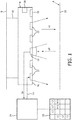
- FIG. 1 illustrates by way of an example, a luminaire 4 suspended by a suspension infrastructure 16 from a ceiling 8 of an area to be illuminated, such as an office.
- the techniques described herein are also applicable to recessed luminaires.
- the luminaire 4 has a direct lighting component which can comprise one or more direct lighting device 22 configured to direct illumination generally downwardly towards a workplane 10 and mounted on a lower surface 42.
- a sensor 12 is provided with a field of view facing outwards which is generally cone-shaped and is denoted by dotted lines.
- a controller 24 is connected to control the luminaire. In this disclosure, the controller operates as a commissioning unit.
- the controller includes a processing unit, executing a computer program to process light signals and output control signals.
- the controller can be provided in the luminaire itself, or can be provided within the space connected to a plurality of similar luminaires and/or other lighting devices in the space.
- the controller 24 receives sensor signals S u from the sensor 12 based on light ⁇ r detected by the sensor 12 within its field of view.
- the sensor signal S u has a level related to the light sensed by the sensor - when converted by the sensor it provides a light signal to the controller 24 representing the sensor input.
- the controller 24 may receive signals from more than one sensor in the space.
- the controller 24 is responsible for adjusting the light output of the lighting components 22 during commissioning while using the detected sensor inputs from the sensor 12 (and possibly from other sensors in the space), for example, by controlling dimming levels, color, beam shape, etc. through control signal 14.
- the controller 24 is operable to implement the first and second phases and to generate an output comprising a fixture map showing the estimated position of luminaires in the space.
- Some luminaires are equipped for a so-called dual-beam concept, wherein a wide beam and/or a narrow beam can be selected by suitably controlling the lighting devices 22.
- the reflection coefficient R1 of the local area under a luminaire is determined in a first phase prior to determining relative distance measurements between luminaires in a second phase.
- Calibration of the local area reflection coefficient is done by measuring the light reflection ⁇ r when powering the lighting component 22 embedded in the same luminaire. When powered, the lighting component 22 sends a flux ⁇ 1 down towards the workplane 10. This results in the reflected flux ⁇ r incident on the sensor 12.
- the luminaire is equipped with a so-called dual-beam concept, it is the narrow beam which is used to determine the local reflection coefficient (in order to reduce second order effects like reflections from walls or windows, etc.), as described more fully later.
- the determined reflection coefficient is used during a commissioning process to modify the sensed values of light reflected from neighboring luminaires as will be described more fully later.
- the light sensor 12 can be implemented as a light diode/transistor.
- a CMOS/CCD camera can also be used the measure the amount of light with more spatial accuracy.
- Such sensors are known in available luminaires.
- Figures 2A and 2B show possible sequences for measuring reflection coefficients.
- Figure 2A illustrates an area in which two luminaires LI, L2 are suspended from a ceiling. Although not shown in Figure 2A , they are under the control of a controller such as controller 24 shown in Figure 1 . For example, the controller first activates a first luminaire L1 to cause it to direct a beam of light ⁇ 1 downwards to the area A1 immediately under the first luminaire.
- the sensor 12 detects the reflected flux ⁇ r as a result of reflection coefficient R1 at the local area A1 which permits the reflection coefficient to be determined.
- R 1 ⁇ r ⁇ 1 , where ⁇ 1 is known based on the output flux of the lighting device 22 for a given control power level on control signal 14, and ⁇ r is converted into detector signal S U .
- the first luminaire L1 is depowered and the second luminaire L2 is powered to carry out the same sequence of steps from which the reflection coefficient R2 of the local area A2 under the second luminaire L2 can be determined.
- the manner in which the reflectance of the intermediate area between two neighboring luminaires is calculated can depend on a number of factors. Sensors provided on luminaires can differ and in particular their directional sensitivity for the detection of light can vary between a relatively narrow angle of detection and a wider, more omnidirectional angle of detection.
- Figure 3 illustrates two luminaires adjacent a window where a narrow angle of sensitivity can be used to receive only light (diffusely) reflected from the surface under the luminaire and filter specular reflected light from, e.g. windows shown at 11 in Figure 3 ).
- some luminaires are equipped with a dual-beam concept which allows the angle of light emitted by the light source of the luminaire to be directed in a narrow angle or in a wider beam (see Figure 4 where the full lines denote a wide beam 22a and the dotted lines a narrow beam 22b.
- the nature of the sensor and light source with which the luminaires are equipped can be taken into account to determine whether it is likely to be more accurate to take two measurements directly downwards of the luminaires as shown in Figures 2A and 2B , and then average these measurements.
- powering only the narrow beam 22b will enable a more accurate assessment of the reflection coefficient of the local area under a luminaire.
- the reflected light may consist of both specular and diffuse contributions.
- the specular contribution can be determined by e.g. combining the wide beam light distribution of the neighboring luminaire with the wide angle sensor of the detecting luminaire.
- the diffuse contribution can be measured by using the wide beam emission and a narrow angle sensor in the detecting luminaire, as shown by the bold line wide beam 22a in Figure 3 .
- Combinations of the two techniques are also anticipated to provide a number of possible measurements which can be utilized in an algorithm to determine the reflection coefficient of an intermediate area.
- the light sensor can be provided with a programmable narrow detection angle (for maximum 20 degrees) to ensure that only the reflection coefficient of the local area under the luminaire is determined, and thereby reducing the contributions of reflections of walls/windows.
- This angle is denoted ⁇ in Figure 1 .
- the reflectance values are stored in suitable storage, such as a memory 30 associated with the controller 24.
- Each reflectance value is associated in connection with the luminaires which share the area for which the reflectance value has been determined.
- a simple matrix example is shown in Figure 1 , wherein for example, the reflectance value associated with the shared area between luminaire 1 and luminaire 2 is marked R12, in the appropriate matrix location. It will readily be appreciated this it is likely that there will be several luminaires in the vicinity and shared spaces associated with each luminaire, where a more complex matrix structure would be required to store the reflectance values.
- FIG 5 shows an example plan view from the underside of a set of luminaires mounted on a ceiling.
- Luminaires LI, L2, L3...Ln are shown in a grid formation, but any formation of luminaires is possible.
- Each luminaire has an associated reflectance value, related to the area it shares with a detecting sensor, as shown in the matrix 33 of Figure 1 . Once the reflectance values for shared areas have been determined and stored, they are used in the second phase of the commissioning method.
- Figure 6 is a schematic perspective of a space in which commissioning is to be conducted.
- the floor 100 may have for example a dark carpet and the space may include light grey tables 110 with a higher reflectivity.
- each luminaire is powered in turn to project light (Luminaire L1 is shown ON in Figure 6 ).
- the sensors 12 associated with all other luminaires in the space are monitored and their signals S u are recorded.
- the storage 30 is accessed to retrieve reflectance values associated with each combination of pair of luminaires or group of luminaires using the sensor number to identify a "recipient" luminaire.
- These reflectance values are used to modify the signals S u received from the relevant recipient luminaires to take into account the reflectance value in the light path from the emitting luminaire.
- the modified signal values can then be used to determine the relative distance from each recipient luminaire from the emitting luminaire in a manner which is known per se.
- the most straightforward implementation is the correction of Su (measured by luminaire Ln) with the local reflectance value Rn, without taking into account the intermediate calculated reflectance values, however intermediate reflectance values can also be taken into account for a more accurate result.
- a further enhancement is tuneable color.
- the reflectance under a luminaire is measured as a function of color ((x,y) or CCT). This can improve signal to noise (S/N) ratio of interluminaire distance measurement.
- the computer program may be stored/distributed on a suitable medium, such as an optical storage medium or a solid state medium supplied together with or as part of other hardware, but may also be distributed in other forms, such as via the Internet or other wired or wireless telecommunication systems. Any reference signs in the claims should not be construed as limiting the scope.
Landscapes
- Circuit Arrangement For Electric Light Sources In General (AREA)
Description
- The present invention relates to lighting commissioning.
- The present disclosure relates to the field of lighting commissioning. With the inroad of digital intelligence in individual light sources, the field of commissioning of lighting control systems to manage such intelligent individual light sources is becoming an increasingly critical step for a successful installation. Proper commissioning is essential for proper equipment operation, user acceptance and reaching target energy savings. For example, Florida Power & Light defines commissioning as a "systematic process of ensuring that all building systems perform interactively according to the documented design intent and the owner's operational needs." Most energy codes now require lighting automation, and the 2005 California Title 24 energy code now requires control system commissioning as part of project certification. While the term "commissioning" might extend over a wide variety of contexts in the field of proper installation of lighting control systems, it is established that in a proper method of commissioning, it is important to derive relative distances between individual luminaires which constitute the lighting components in a lighting system to be installed. This allows the establishment of a fixture map with relative positions of the luminaires and standalone sensors and controls, which enables the luminaires to be assigned to different groups within the luminaire landscape and thus to be controlled as groups.
- While in principle, there are enormous advantages to be gained by the new lighting systems incorporating intelligent luminaires, in fact traditional cost and required resources for installation and proper commissioning of such complex lighting systems may form a bottleneck for involved decision makers, and may inhibit the take-up of the opportunities to be offered by intelligent lighting systems. With a properly commissioned system however, embedded and automatic lighting control systems can reduce lighting consumption by 20% to 40% in existing buildings and new constructions, as compared with conventional lighting systems.
- Thus, so-called auto commissioning techniques are being developed.
-
US Patent No. 8159156 describes a method of auto commissioning in which a fixture map is derived by determining the relative distances between the individual luminaires. The luminaires are equipped with light sensors which are therefore co-located with each luminaire. By sequential emission of light by the individual luminaires, the amount of light detected at the other luminaires can be converted into a relative distance measurement. As a result, a map with the relative positions of the luminaires can be created. Finally, the luminaires can be assigned to different groups defined with this luminaire landscape. -
PCT application WO2013/068866 describes a method for determining presence of objects in an area surrounding a luminaire. The method includes determining whether objects are present in the area surrounding the luminaire based on a comparison of information regarding a first and a second light beam indicating signal strength of the detected back-reflected light of each respective light beam. - This application also discloses a method for determining the distance between luminaires based on reflected light from a neighbouring luminaire and taking into account the reflectance value associated with the reflecting surface between luminaires.
- The inventors have recognized some practical difficulties associated with the auto commissioning system described in
US 8159156 . For typical office lighting installations, the luminaires which are used are recessed into or suspended from the ceiling (consider for example Philips' PowerBalance luminaire family). The amount of light detected by an embedded light sensor in the luminaire thus strongly depends on the reflection coefficient of the projected local area, directly under the luminaire. The inventors have recognized that the relative distance measurements established using the technique described inUS 8159156 based on the light levels from surrounding luminaires are likely to be flawed because light sensor measurements can fluctuate significantly due to non-uniformly distributed reflectivity in their surrounding area (e.g. open office space). For example, tables may have a higher reflective surface than the surrounding floor. The fixture map obtained inUS 8159156 uses a triangulation method based on mapping circles with the measured distances. Different reflectance can affect significantly the accuracy of distance measurement. - According to one aspect of the invention, there is provided a lighting commissioning system comprising:
- a plurality of luminaires, each luminaire co-located with a light source and a light sensor;
- a controller configured to selectively control the light sources to emit light and to receive signals from the light sensors representative of light sensed thereby; and a memory accessible to the controller; wherein the controller is configured to execute a first phase of commissioning to determine at least one reflectance value associated with a reflecting surface in a light path to each light sensor, and to store the reflectance values in the memory, and a second phase of commissioning in which the reflectance values are accessed by the controller for converting light sensed by each light sensor from an emitting light source into a measure of a distance between the emitting light source and the sensor.
- Another aspect of the invention provides a method of determining a distance from a first luminaire to a second luminaire comprising: causing a light source co-located with the second luminaire to emit light directed towards a reflecting surface; detecting a level of reflected light from the reflecting surface using a sensor co-located with the first luminaire; accessing a reflectance value determined for the reflecting surface; modifying the level of reflected light to take into account the accessed reflectance value; and using the modified measure of emitted light to provide a measure of a distance between the first and second luminaires.
- The reflectance value represents the reflection coefficient of the reflecting surface, and in some embodiments can be the reflection coefficient. In other embodiments, where a level of emitted light from the light sources is common across multiple measurements, the reflected light itself can provide a reflectance value suitable for modifying the level of reflected light.
- The following described embodiments present an exemplifying technique with four steps of a commissioning process:
- Step 1: Determine reflection coefficients of areas under and nearby individual luminaires
- Step 2: Measure sequentially different light levels by controlling different combinations of luminaires (light sources) and sensors
- Step 3: Determine relative distances between luminaires using the reflection coefficients of
Step 1. - Step 4: Derive fixture map from relative distances between luminaires
- For a better of understanding the present invention and to show how the same may be carried into effect, reference will now be made by way of example to the accompanying drawings.
-
-
Fig. 1 is a schematic block diagram of a controlled luminaire; -
Figs. 2A and 2B are schematic diagrams illustrating steps in calculation of a reflection coefficient; -
Fig. 3 is a schematic diagram illustrating sensor angle sensitivity; -
Fig. 4 is a schematic diagram illustrating dual beam illumination; -
Fig. 5 is a schematic plan view from the underside showing an array of luminaires; and -
Fig. 6 is a perspective view of a space during commissioning. - In the embodiments discussed in the present disclosure, a method of determining a distance from a first luminaire to a second luminaire is described in which the conversion of the light level into a distance measurement takes into account a determined reflection coefficient. In one embodiment, the reflection coefficient is assessed by using a local light source in the luminaire above a local reflection area, and calibrating the reflection coefficient by using an embedded sensor in the same luminaire. Assuming the reflection of the local surface is of a Lambertian type, the assessed reflection coefficient can also be used to convert the measured light intensity related to the light emitted by other luminaires in the same office area.
- As described in the following, a first phase in a method of commissioning a lighting system involves determining reflection coefficients and a second phase involves using the determined reflection coefficients in a method of determining distance between luminaires. The distance measures can be used to obtain a fixture map, for example using a triangulation method of plotting circles as described in
US 8159156 . -
Figure 1 illustrates by way of an example, a luminaire 4 suspended by asuspension infrastructure 16 from aceiling 8 of an area to be illuminated, such as an office. The techniques described herein are also applicable to recessed luminaires. The luminaire 4 has a direct lighting component which can comprise one or moredirect lighting device 22 configured to direct illumination generally downwardly towards aworkplane 10 and mounted on alower surface 42. In addition, asensor 12 is provided with a field of view facing outwards which is generally cone-shaped and is denoted by dotted lines. To complete the picture but in a diagrammatic form, acontroller 24 is connected to control the luminaire. In this disclosure, the controller operates as a commissioning unit. The controller includes a processing unit, executing a computer program to process light signals and output control signals. The controller can be provided in the luminaire itself, or can be provided within the space connected to a plurality of similar luminaires and/or other lighting devices in the space. Thecontroller 24 receives sensor signals Su from thesensor 12 based on light ϕr detected by thesensor 12 within its field of view. The sensor signal Su has a level related to the light sensed by the sensor - when converted by the sensor it provides a light signal to thecontroller 24 representing the sensor input. Thecontroller 24 may receive signals from more than one sensor in the space. In use of the lighting system, thecontroller 24 is responsible for adjusting the light output of thelighting components 22 during commissioning while using the detected sensor inputs from the sensor 12 (and possibly from other sensors in the space), for example, by controlling dimming levels, color, beam shape, etc. throughcontrol signal 14. In the commissioning stage, thecontroller 24 is operable to implement the first and second phases and to generate an output comprising a fixture map showing the estimated position of luminaires in the space. - Some luminaires are equipped for a so-called dual-beam concept, wherein a wide beam and/or a narrow beam can be selected by suitably controlling the
lighting devices 22. - According to the commissioning method of the present disclosure, the reflection coefficient R1 of the local area under a luminaire, generally denoted A on the
workplane 10, is determined in a first phase prior to determining relative distance measurements between luminaires in a second phase. Calibration of the local area reflection coefficient is done by measuring the light reflection ϕr when powering thelighting component 22 embedded in the same luminaire. When powered, thelighting component 22 sends a flux ϕ1 down towards theworkplane 10. This results in the reflected flux ϕr incident on thesensor 12. When the luminaire is equipped with a so-called dual-beam concept, it is the narrow beam which is used to determine the local reflection coefficient (in order to reduce second order effects like reflections from walls or windows, etc.), as described more fully later. - The determined reflection coefficient is used during a commissioning process to modify the sensed values of light reflected from neighboring luminaires as will be described more fully later.
- The
light sensor 12 can be implemented as a light diode/transistor. A CMOS/CCD camera can also be used the measure the amount of light with more spatial accuracy. Such sensors are known in available luminaires.Figures 2A and 2B show possible sequences for measuring reflection coefficients.Figure 2A illustrates an area in which two luminaires LI, L2 are suspended from a ceiling. Although not shown inFigure 2A , they are under the control of a controller such ascontroller 24 shown inFigure 1 . For example, the controller first activates a first luminaire L1 to cause it to direct a beam of light ϕ1 downwards to the area A1 immediately under the first luminaire. Thesensor 12 detects the reflected flux ϕr as a result of reflection coefficient R1 at the local area A1 which permits the reflection coefficient to be determined. For example,
lighting device 22 for a given control power level oncontrol signal 14, and ϕr is converted into detector signal SU. - Then, moving to
Figure 2B , the first luminaire L1 is depowered and the second luminaire L2 is powered to carry out the same sequence of steps from which the reflection coefficient R2 of the local area A2 under the second luminaire L2 can be determined. - Once R1 and R2 are known, they are applied to an algorithm to determine the reflectance value of an intermediate area A1/2 shared by the luminaires, for
example 
- The manner in which the reflectance of the intermediate area between two neighboring luminaires is calculated can depend on a number of factors. Sensors provided on luminaires can differ and in particular their directional sensitivity for the detection of light can vary between a relatively narrow angle of detection and a wider, more omnidirectional angle of detection.
Figure 3 illustrates two luminaires adjacent a window where a narrow angle of sensitivity can be used to receive only light (diffusely) reflected from the surface under the luminaire and filter specular reflected light from, e.g. windows shown at 11 inFigure 3 ). - Moreover, as mentioned, some luminaires are equipped with a dual-beam concept which allows the angle of light emitted by the light source of the luminaire to be directed in a narrow angle or in a wider beam (see
Figure 4 where the full lines denote awide beam 22a and the dotted lines anarrow beam 22b. When determining how to make the optimum measurement of the reflection coefficient of an intermediate area between two luminaires, the nature of the sensor and light source with which the luminaires are equipped can be taken into account to determine whether it is likely to be more accurate to take two measurements directly downwards of the luminaires as shown inFigures 2A and 2B , and then average these measurements. In the case of a luminaire with a dual-beam concept, powering only thenarrow beam 22b will enable a more accurate assessment of the reflection coefficient of the local area under a luminaire. - As illustrated in
Figure 3 , the reflected light (emitted by a neighboring luminaire) may consist of both specular and diffuse contributions. The specular contribution can be determined by e.g. combining the wide beam light distribution of the neighboring luminaire with the wide angle sensor of the detecting luminaire. The diffuse contribution can be measured by using the wide beam emission and a narrow angle sensor in the detecting luminaire, as shown by the bold linewide beam 22a inFigure 3 . - Combinations of the two techniques are also anticipated to provide a number of possible measurements which can be utilized in an algorithm to determine the reflection coefficient of an intermediate area.
- As a further improvement, the light sensor can be provided with a programmable narrow detection angle (for maximum 20 degrees) to ensure that only the reflection coefficient of the local area under the luminaire is determined, and thereby reducing the contributions of reflections of walls/windows. This angle is denoted θ in
Figure 1 . - Once determined, the reflectance values are stored in suitable storage, such as a memory 30 associated with the
controller 24. Each reflectance value is associated in connection with the luminaires which share the area for which the reflectance value has been determined. A simple matrix example is shown inFigure 1 , wherein for example, the reflectance value associated with the shared area betweenluminaire 1 andluminaire 2 is marked R12, in the appropriate matrix location. It will readily be appreciated this it is likely that there will be several luminaires in the vicinity and shared spaces associated with each luminaire, where a more complex matrix structure would be required to store the reflectance values. -
Figure 5 shows an example plan view from the underside of a set of luminaires mounted on a ceiling. Luminaires LI, L2, L3...Ln are shown in a grid formation, but any formation of luminaires is possible. Each luminaire has an associated reflectance value, related to the area it shares with a detecting sensor, as shown in thematrix 33 ofFigure 1 . Once the reflectance values for shared areas have been determined and stored, they are used in the second phase of the commissioning method. -
Figure 6 is a schematic perspective of a space in which commissioning is to be conducted. Thefloor 100 may have for example a dark carpet and the space may include light grey tables 110 with a higher reflectivity. - In the second phase, each luminaire is powered in turn to project light (Luminaire L1 is shown ON in
Figure 6 ). When one luminaire is powered, thesensors 12 associated with all other luminaires in the space are monitored and their signals Su are recorded. Then, the storage 30 is accessed to retrieve reflectance values associated with each combination of pair of luminaires or group of luminaires using the sensor number to identify a "recipient" luminaire. These reflectance values are used to modify the signals Su received from the relevant recipient luminaires to take into account the reflectance value in the light path from the emitting luminaire. The modified signal values can then be used to determine the relative distance from each recipient luminaire from the emitting luminaire in a manner which is known per se. The most straightforward implementation is the correction of Su (measured by luminaire Ln) with the local reflectance value Rn, without taking into account the intermediate calculated reflectance values, however intermediate reflectance values can also be taken into account for a more accurate result. - The formula to calculate "interluminaire" distance is given below:

- where
flux 1 is the luminous flux emitted byLum 1 - R2 is the reflectance under Lum2
- Int2 is the light intensity measured by sensor embedded in Lum2 (Int2)
- D1-2 is the distance between Lum1 and Lum2
- Amb is the ambient light contribution (by dimming the emitting luminaire, the factor Amb can be determined); and
- C is constant (e.g. depending on sensor sensitivity)
- A further enhancement is tuneable color. The reflectance under a luminaire is measured as a function of color ((x,y) or CCT). This can improve signal to noise (S/N) ratio of interluminaire distance measurement.
- Other variations to the disclosed embodiments can be understood and effected by those skilled in the art in practice in the claimed invention, from a study of the drawings, the disclosure and the appended claims. In the claims, the word "comprising" does not exclude other elements or steps, and the indefinite article "a" or "an" does not exclude a plurality. A single processor or other unit may fulfill the functions of several items recited in the claims. The mere fact that certain measures are cited in mutually different dependent claims does not indicate that a combination of these measures cannot be used to advantage. The computer program may be stored/distributed on a suitable medium, such as an optical storage medium or a solid state medium supplied together with or as part of other hardware, but may also be distributed in other forms, such as via the Internet or other wired or wireless telecommunication systems. Any reference signs in the claims should not be construed as limiting the scope.
Claims (13)
- A lighting commissioning system comprising:a plurality of luminaires (L1, L2), each luminaire co-located with a light source (22) and a light sensor (12);a controller (24) configured to selectively control the light sources to emit light and to receive signals from the light sensors representative of light sensed thereby; anda memory (33) accessible to the controller; characterized in that the controller is configured to execute a first phase of commissioning by executing an algorithm to calculate at least one reflectance value (R12) associated with a reflecting surface which lies between a local area of a luminaire and a local area of a neighboring luminaire (A1/2), and to store the one or more reflectance values in the memory, and a second phase of commissioning in which the reflectance values are accessed by the controller for converting light sensed by each light sensor from an emitting light source into a measure of distance between the emitting light source and each light sensor;wherein the controller is configured in the first phase of commissioning to carry out the steps of:activating a light source of a first luminaire (L1);measuring light reflected from a local area to a light sensor on the first luminaire;determining a reflection coefficient for the local area (R1); andrepeating the steps for at least one neighboring luminaire (L2) to thereby determine at least one additional reflection coefficient for a local area under the neighboring luminaire (R2); andexecuting an algorithm on the reflection coefficients to calculate the at least one reflectance value associated with the reflecting surface which lies between the local area of the first luminaire and the local area of the at least one neighboring luminaire.
- A system according to claim 1, wherein the algorithm generates an average of the reflection coefficients.
- A system according to claim 1, wherein the light source of at least some of the plurality of luminaires is controllable into a first mode with a narrow beam and a second mode with a broader beam.
- A system according to claim 1, wherein the light sensor for each luminaire is selected from a directional light sensor and an omnidirectional light sensor.
- A system according to claim 4, wherein the sensor angle of the directional sensor is programmable.
- A system according to claim 1, wherein the memory holds a matrix of reflectance values, each reflectance value associated with an intermediate area between neighboring luminaires identified in the matrix.
- A system according to claim 1, wherein the controller is configured to operate in the second phase of commissioning to determine a fixture map of light sources and sensors using the determined distances.
- A commissioning system according to claim 1, comprising at least one fixture light sensor under the control of the controller, whereby a position of the at least one fixture sensor can be determined in the second phase of commissioning based on light sensed at the least one fixture sensor.
- A commissioning system according to claim 8, wherein the fixture sensor is stand alone or is co-located with a fixture comprising a light control such as a light switch or dimmer.
- A commissioning system according to claim 1, wherein the light source of at least some of the luminaries is controllable to emit light of different color, whereby reflectance values for different colored light can be determined.
- A method of commissioning a lighting system, wherein said lighting system comprises a plurality of luminaires, each luminaire co-located with a light source and a light sensor, a controller configured to selectively control the light sources to emit light and to receive signals from the light sensors representative of light sensed thereby; and a memory accessible to the controller, characterized in that the controller is configured to execute a first phase of commissioning by executing an algorithm to calculate at least one reflectance value associated with a reflecting surface which lies between a local area of a luminaire and a local area of a neighboring luminaire, and to store one or more the reflectance values in the memory, and a second phase of commissioning in which the reflectance values are accessed by the controller for converting light sensed by each light sensor from an emitting light source into a measure of distance between the emitting light source and each light sensor;
wherein said method comprises, in a first phase of said commissioning, the following steps performed by the controller:activating a light source of a first luminaire;measuring light reflected from a local area to a light sensor on the first luminaire;determining a reflection coefficient for the local area; andrepeating the steps for at least one neighboring luminaire to thereby determine at least one additional reflection coefficient for a local area under the neighboring luminaire; andexecuting an algorithm on the reflection coefficients to calculate the at least one reflectance value associated with the reflecting surface which lies between the local area of the first luminaire and the local area of the at least one neighboring luminaire. - A method according to claim 11, when used in commissioning a lighting system to determine a fixture map of luminaires based on the distance measurements.
- A method according to claim 11, wherein said method further comprises, in said second phase of said commissioning, the steps of:causing a light source co-located with the second luminaire to emit light directed towards a reflecting surface;detecting a level of reflected light from the reflecting surface using a sensor co-located with the first luminaire;accessing a reflectance value determined for the reflecting surface;modifying the detected level of reflected light to take into account the accessed reflectance value; andusing the modified measure to provide a measure of a distance between the first and second luminaires.
Priority Applications (1)
| Application Number | Priority Date | Filing Date | Title |
|---|---|---|---|
| EP14757949.4A EP3042545B1 (en) | 2013-09-03 | 2014-09-01 | Lighting commissioning |
Applications Claiming Priority (3)
| Application Number | Priority Date | Filing Date | Title |
|---|---|---|---|
| EP13182861 | 2013-09-03 | ||
| PCT/EP2014/068523 WO2015032721A1 (en) | 2013-09-03 | 2014-09-01 | Lighting commissioning |
| EP14757949.4A EP3042545B1 (en) | 2013-09-03 | 2014-09-01 | Lighting commissioning |
Publications (2)
| Publication Number | Publication Date |
|---|---|
| EP3042545A1 EP3042545A1 (en) | 2016-07-13 |
| EP3042545B1 true EP3042545B1 (en) | 2018-12-19 |
Family
ID=49080819
Family Applications (1)
| Application Number | Title | Priority Date | Filing Date |
|---|---|---|---|
| EP14757949.4A Not-in-force EP3042545B1 (en) | 2013-09-03 | 2014-09-01 | Lighting commissioning |
Country Status (5)
| Country | Link |
|---|---|
| US (1) | US9713232B2 (en) |
| EP (1) | EP3042545B1 (en) |
| JP (1) | JP6164673B2 (en) |
| CN (1) | CN105659704B (en) |
| WO (1) | WO2015032721A1 (en) |
Families Citing this family (25)
| Publication number | Priority date | Publication date | Assignee | Title |
|---|---|---|---|---|
| EP3146362B1 (en) | 2014-05-23 | 2019-08-14 | Signify Holding B.V. | Object detection system and method |
| JP6447915B2 (en) * | 2015-03-13 | 2019-01-09 | パナソニックIpマネジメント株式会社 | Load control device |
| WO2017003931A1 (en) * | 2015-06-27 | 2017-01-05 | Brown Gregory A M | Light fixtures, systems, and methods for operating and/or controlling light fixtures |
| KR102502449B1 (en) * | 2015-10-05 | 2023-02-22 | 삼성전자주식회사 | Device and method to display illumination |
| EP3384467B1 (en) * | 2015-12-03 | 2020-02-26 | Osram Sylvania Inc. | Light-based vehicle positioning for mobile transport systems |
| US10671826B2 (en) * | 2016-02-08 | 2020-06-02 | Ideal Industries Lighting Llc | Indoor location services using a distributed lighting network |
| US10211660B2 (en) | 2016-02-08 | 2019-02-19 | Cree, Inc. | LED lighting device with adaptive profiles for controlling power consumption |
| JP6692047B2 (en) * | 2016-04-21 | 2020-05-13 | パナソニックIpマネジメント株式会社 | Lighting control system |
| US10132687B2 (en) | 2016-06-30 | 2018-11-20 | Gooee Limited | Three-dimensional VLC/DLC sensor clip |
| US10687407B2 (en) * | 2016-08-23 | 2020-06-16 | Signify Holding B.V. | Wireless luminaire configuration |
| US10451229B2 (en) | 2017-01-30 | 2019-10-22 | Ideal Industries Lighting Llc | Skylight fixture |
| US10465869B2 (en) | 2017-01-30 | 2019-11-05 | Ideal Industries Lighting Llc | Skylight fixture |
| WO2018141664A1 (en) | 2017-02-02 | 2018-08-09 | Philips Lighting Holding B.V. | A lighting enabled system and methods for building evacuation planning |
| US10122455B1 (en) | 2017-05-01 | 2018-11-06 | Gooee Limited | VLC/DLC Sectorized communication |
| US9992838B1 (en) * | 2017-05-01 | 2018-06-05 | Gooee Limited | Automated luminaire identification and group assignment devices, systems, and methods using dimming function |
| US11055867B2 (en) * | 2017-05-02 | 2021-07-06 | Jdrf Electromag Engineering Inc. | Automatic light position detection system |
| GB2564248B (en) * | 2017-05-25 | 2020-05-27 | Gooee Ltd | Automated Luminaire Location Identification and Group Assignment Using Light Based Communication For Commissioning a Lighting Control System |
| WO2018215989A1 (en) * | 2017-05-25 | 2018-11-29 | Gooee Limited | Automated luminaire location identification and group assignment using light based communication for commissioning a lighting control system |
| US9894740B1 (en) | 2017-06-13 | 2018-02-13 | Cree, Inc. | Intelligent lighting module for a lighting fixture |
| US11419201B2 (en) | 2019-10-28 | 2022-08-16 | Ideal Industries Lighting Llc | Systems and methods for providing dynamic lighting |
| US10830400B2 (en) | 2018-02-08 | 2020-11-10 | Ideal Industries Lighting Llc | Environmental simulation for indoor spaces |
| DE102018216474B4 (en) * | 2018-09-26 | 2025-03-27 | Inventronics Gmbh | Method for assigning light sensors for lighting control in a lighting system |
| IT201900018161A1 (en) * | 2019-10-08 | 2021-04-08 | Ledworks Srl | Lighting system and control method of said system |
| US11382202B2 (en) * | 2020-08-27 | 2022-07-05 | Himax Imaging Limited | Method and apparatus for controlling a lighting fixture based on motion detection and related lighting fixture |
| EP4353052A4 (en) * | 2021-06-10 | 2025-04-02 | JDRF Electromag Engineering Inc. | Lighting device groupings |
Citations (1)
| Publication number | Priority date | Publication date | Assignee | Title |
|---|---|---|---|---|
| WO2013068866A1 (en) * | 2011-11-10 | 2013-05-16 | Koninklijke Philips Electronics N.V. | Presence detection using split beam luminaire |
Family Cites Families (16)
| Publication number | Priority date | Publication date | Assignee | Title |
|---|---|---|---|---|
| JP2511391B2 (en) * | 1991-12-04 | 1996-06-26 | シーメンス アクチエンゲゼルシヤフト | Optical distance sensor |
| WO2002048645A1 (en) * | 2000-12-11 | 2002-06-20 | Mitsubishi Denki Kabushiki Kaisha | Sensor head |
| US20040002792A1 (en) | 2002-06-28 | 2004-01-01 | Encelium Technologies Inc. | Lighting energy management system and method |
| JP2005331468A (en) | 2004-05-21 | 2005-12-02 | Sharp Corp | Lighting device with ranging function |
| WO2007034399A1 (en) * | 2005-09-26 | 2007-03-29 | Philips Intellectual Property & Standards Gmbh | Method and device for grouping at least three lamps |
| WO2008078253A2 (en) | 2006-12-22 | 2008-07-03 | Koninklijke Philips Electronics N.V. | Device for controlling light sources |
| US20090146982A1 (en) * | 2007-12-05 | 2009-06-11 | Jeff Thielman | Lighting Calibration System and Method |
| JPWO2010119482A1 (en) * | 2009-04-16 | 2012-10-18 | トヨタ自動車株式会社 | Distance detection device and method used in the device |
| US8159156B2 (en) * | 2009-08-10 | 2012-04-17 | Redwood Systems, Inc. | Lighting systems and methods of auto-commissioning |
| EP2578062B1 (en) * | 2010-06-03 | 2013-11-13 | Koninklijke Philips N.V. | Configuration unit and method for configuring a presence detection sensor |
| US20120001841A1 (en) * | 2010-06-30 | 2012-01-05 | Jeff Gokingco | Identifying ambient light type and illuminance compensation using a plurality of photodetectors |
| US9297643B2 (en) | 2011-11-10 | 2016-03-29 | Koninklijke Philips N.V. | Distance estimation using split beam luminaire |
| JP2013120623A (en) * | 2011-12-06 | 2013-06-17 | Panasonic Corp | Lighting system |
| US8860316B2 (en) | 2011-12-16 | 2014-10-14 | Redwood Systems, Inc. | Selective light sensor and daylight management |
| JP6041188B2 (en) * | 2012-06-01 | 2016-12-07 | パナソニックIpマネジメント株式会社 | Sensor device |
| WO2014001965A1 (en) * | 2012-06-27 | 2014-01-03 | Koninklijke Philips N.V. | Methods and apparatus for automatically adapting light output of a lighting unit |
-
2014
- 2014-09-01 JP JP2016516028A patent/JP6164673B2/en not_active Expired - Fee Related
- 2014-09-01 US US14/916,304 patent/US9713232B2/en not_active Expired - Fee Related
- 2014-09-01 WO PCT/EP2014/068523 patent/WO2015032721A1/en not_active Ceased
- 2014-09-01 CN CN201480048679.XA patent/CN105659704B/en not_active Expired - Fee Related
- 2014-09-01 EP EP14757949.4A patent/EP3042545B1/en not_active Not-in-force
Patent Citations (1)
| Publication number | Priority date | Publication date | Assignee | Title |
|---|---|---|---|---|
| WO2013068866A1 (en) * | 2011-11-10 | 2013-05-16 | Koninklijke Philips Electronics N.V. | Presence detection using split beam luminaire |
Also Published As
| Publication number | Publication date |
|---|---|
| US20160205749A1 (en) | 2016-07-14 |
| CN105659704A (en) | 2016-06-08 |
| CN105659704B (en) | 2019-02-22 |
| US9713232B2 (en) | 2017-07-18 |
| EP3042545A1 (en) | 2016-07-13 |
| JP2016529646A (en) | 2016-09-23 |
| WO2015032721A1 (en) | 2015-03-12 |
| JP6164673B2 (en) | 2017-07-19 |
Similar Documents
| Publication | Publication Date | Title |
|---|---|---|
| US9713232B2 (en) | Lighting commissioning | |
| JP5960937B2 (en) | Lighting device calibration operation | |
| RU2610426C2 (en) | Presence detection using split beam luminaire | |
| US9967952B2 (en) | Demand response for networked distributed lighting systems | |
| JP5749932B2 (en) | Consistent color calibration in LED-type lighting equipment | |
| RU2617912C2 (en) | Distance assessment using lighting devices with split beam | |
| CN108029180B (en) | System and method for location mapping of lighting fixtures | |
| US20130229115A1 (en) | Methods for Disaggregated Sensing of Artificial Light and Daylight Distribution | |
| JP6258947B2 (en) | Calibration of light sensor | |
| US20190037667A1 (en) | Lighting system and a method of controlling the light output from a luminaire | |
| JP2019200938A (en) | Illumination control system | |
| JP5750756B2 (en) | Lighting control method and lighting control system | |
| EP3269212B1 (en) | Calibration of light sensors | |
| JP5509365B1 (en) | Control program and environmental control system | |
| WO2014170292A1 (en) | Luminaire and control thereof | |
| CN103621184B (en) | Healthy and strong daylight by means of encoded light is integrated | |
| CA3003010C (en) | Automatic light position detection system | |
| US10512138B1 (en) | Systems and methods for self learning ambient light sensors | |
| CN111145332A (en) | General method for designing photometry for home decoration | |
| KR101127815B1 (en) | Lighting Control Device | |
| WO2025243284A1 (en) | Systems and methods for improving illumination efficiency in an area of interest | |
| JP2026044047A (en) | Lighting control device, lighting control system, lighting control method, and lighting control program |
Legal Events
| Date | Code | Title | Description |
|---|---|---|---|
| PUAI | Public reference made under article 153(3) epc to a published international application that has entered the european phase |
Free format text: ORIGINAL CODE: 0009012 |
|
| 17P | Request for examination filed |
Effective date: 20160404 |
|
| AK | Designated contracting states |
Kind code of ref document: A1 Designated state(s): AL AT BE BG CH CY CZ DE DK EE ES FI FR GB GR HR HU IE IS IT LI LT LU LV MC MK MT NL NO PL PT RO RS SE SI SK SM TR |
|
| AX | Request for extension of the european patent |
Extension state: BA ME |
|
| 17Q | First examination report despatched |
Effective date: 20160907 |
|
| STAA | Information on the status of an ep patent application or granted ep patent |
Free format text: STATUS: EXAMINATION IS IN PROGRESS |
|
| DAX | Request for extension of the european patent (deleted) | ||
| RIN1 | Information on inventor provided before grant (corrected) |
Inventor name: CREUSEN, MARTINUS PETRUS Inventor name: JAMES, ALEXANDER |
|
| GRAP | Despatch of communication of intention to grant a patent |
Free format text: ORIGINAL CODE: EPIDOSNIGR1 |
|
| STAA | Information on the status of an ep patent application or granted ep patent |
Free format text: STATUS: GRANT OF PATENT IS INTENDED |
|
| INTG | Intention to grant announced |
Effective date: 20171027 |
|
| GRAJ | Information related to disapproval of communication of intention to grant by the applicant or resumption of examination proceedings by the epo deleted |
Free format text: ORIGINAL CODE: EPIDOSDIGR1 |
|
| STAA | Information on the status of an ep patent application or granted ep patent |
Free format text: STATUS: EXAMINATION IS IN PROGRESS |
|
| INTC | Intention to grant announced (deleted) | ||
| GRAP | Despatch of communication of intention to grant a patent |
Free format text: ORIGINAL CODE: EPIDOSNIGR1 |
|
| STAA | Information on the status of an ep patent application or granted ep patent |
Free format text: STATUS: GRANT OF PATENT IS INTENDED |
|
| INTG | Intention to grant announced |
Effective date: 20180705 |
|
| GRAS | Grant fee paid |
Free format text: ORIGINAL CODE: EPIDOSNIGR3 |
|
| GRAA | (expected) grant |
Free format text: ORIGINAL CODE: 0009210 |
|
| STAA | Information on the status of an ep patent application or granted ep patent |
Free format text: STATUS: THE PATENT HAS BEEN GRANTED |
|
| RAP1 | Party data changed (applicant data changed or rights of an application transferred) |
Owner name: PHILIPS LIGHTING HOLDING B.V. |
|
| AK | Designated contracting states |
Kind code of ref document: B1 Designated state(s): AL AT BE BG CH CY CZ DE DK EE ES FI FR GB GR HR HU IE IS IT LI LT LU LV MC MK MT NL NO PL PT RO RS SE SI SK SM TR |
|
| REG | Reference to a national code |
Ref country code: GB Ref legal event code: FG4D |
|
| REG | Reference to a national code |
Ref country code: CH Ref legal event code: EP |
|
| REG | Reference to a national code |
Ref country code: IE Ref legal event code: FG4D |
|
| REG | Reference to a national code |
Ref country code: DE Ref legal event code: R096 Ref document number: 602014038247 Country of ref document: DE |
|
| REG | Reference to a national code |
Ref country code: AT Ref legal event code: REF Ref document number: 1080089 Country of ref document: AT Kind code of ref document: T Effective date: 20190115 |
|
| RAP2 | Party data changed (patent owner data changed or rights of a patent transferred) |
Owner name: SIGNIFY HOLDING B.V. |
|
| REG | Reference to a national code |
Ref country code: NL Ref legal event code: MP Effective date: 20181219 |
|
| PG25 | Lapsed in a contracting state [announced via postgrant information from national office to epo] |
Ref country code: HR Free format text: LAPSE BECAUSE OF FAILURE TO SUBMIT A TRANSLATION OF THE DESCRIPTION OR TO PAY THE FEE WITHIN THE PRESCRIBED TIME-LIMIT Effective date: 20181219 Ref country code: LT Free format text: LAPSE BECAUSE OF FAILURE TO SUBMIT A TRANSLATION OF THE DESCRIPTION OR TO PAY THE FEE WITHIN THE PRESCRIBED TIME-LIMIT Effective date: 20181219 Ref country code: BG Free format text: LAPSE BECAUSE OF FAILURE TO SUBMIT A TRANSLATION OF THE DESCRIPTION OR TO PAY THE FEE WITHIN THE PRESCRIBED TIME-LIMIT Effective date: 20190319 Ref country code: FI Free format text: LAPSE BECAUSE OF FAILURE TO SUBMIT A TRANSLATION OF THE DESCRIPTION OR TO PAY THE FEE WITHIN THE PRESCRIBED TIME-LIMIT Effective date: 20181219 Ref country code: LV Free format text: LAPSE BECAUSE OF FAILURE TO SUBMIT A TRANSLATION OF THE DESCRIPTION OR TO PAY THE FEE WITHIN THE PRESCRIBED TIME-LIMIT Effective date: 20181219 Ref country code: NO Free format text: LAPSE BECAUSE OF FAILURE TO SUBMIT A TRANSLATION OF THE DESCRIPTION OR TO PAY THE FEE WITHIN THE PRESCRIBED TIME-LIMIT Effective date: 20190319 |
|
| REG | Reference to a national code |
Ref country code: LT Ref legal event code: MG4D |
|
| REG | Reference to a national code |
Ref country code: AT Ref legal event code: MK05 Ref document number: 1080089 Country of ref document: AT Kind code of ref document: T Effective date: 20181219 |
|
| PG25 | Lapsed in a contracting state [announced via postgrant information from national office to epo] |
Ref country code: RS Free format text: LAPSE BECAUSE OF FAILURE TO SUBMIT A TRANSLATION OF THE DESCRIPTION OR TO PAY THE FEE WITHIN THE PRESCRIBED TIME-LIMIT Effective date: 20181219 Ref country code: AL Free format text: LAPSE BECAUSE OF FAILURE TO SUBMIT A TRANSLATION OF THE DESCRIPTION OR TO PAY THE FEE WITHIN THE PRESCRIBED TIME-LIMIT Effective date: 20181219 Ref country code: GR Free format text: LAPSE BECAUSE OF FAILURE TO SUBMIT A TRANSLATION OF THE DESCRIPTION OR TO PAY THE FEE WITHIN THE PRESCRIBED TIME-LIMIT Effective date: 20190320 Ref country code: SE Free format text: LAPSE BECAUSE OF FAILURE TO SUBMIT A TRANSLATION OF THE DESCRIPTION OR TO PAY THE FEE WITHIN THE PRESCRIBED TIME-LIMIT Effective date: 20181219 |
|
| PG25 | Lapsed in a contracting state [announced via postgrant information from national office to epo] |
Ref country code: NL Free format text: LAPSE BECAUSE OF FAILURE TO SUBMIT A TRANSLATION OF THE DESCRIPTION OR TO PAY THE FEE WITHIN THE PRESCRIBED TIME-LIMIT Effective date: 20181219 |
|
| PG25 | Lapsed in a contracting state [announced via postgrant information from national office to epo] |
Ref country code: PL Free format text: LAPSE BECAUSE OF FAILURE TO SUBMIT A TRANSLATION OF THE DESCRIPTION OR TO PAY THE FEE WITHIN THE PRESCRIBED TIME-LIMIT Effective date: 20181219 Ref country code: ES Free format text: LAPSE BECAUSE OF FAILURE TO SUBMIT A TRANSLATION OF THE DESCRIPTION OR TO PAY THE FEE WITHIN THE PRESCRIBED TIME-LIMIT Effective date: 20181219 Ref country code: PT Free format text: LAPSE BECAUSE OF FAILURE TO SUBMIT A TRANSLATION OF THE DESCRIPTION OR TO PAY THE FEE WITHIN THE PRESCRIBED TIME-LIMIT Effective date: 20190419 Ref country code: CZ Free format text: LAPSE BECAUSE OF FAILURE TO SUBMIT A TRANSLATION OF THE DESCRIPTION OR TO PAY THE FEE WITHIN THE PRESCRIBED TIME-LIMIT Effective date: 20181219 Ref country code: IT Free format text: LAPSE BECAUSE OF FAILURE TO SUBMIT A TRANSLATION OF THE DESCRIPTION OR TO PAY THE FEE WITHIN THE PRESCRIBED TIME-LIMIT Effective date: 20181219 |
|
| PG25 | Lapsed in a contracting state [announced via postgrant information from national office to epo] |
Ref country code: SK Free format text: LAPSE BECAUSE OF FAILURE TO SUBMIT A TRANSLATION OF THE DESCRIPTION OR TO PAY THE FEE WITHIN THE PRESCRIBED TIME-LIMIT Effective date: 20181219 Ref country code: EE Free format text: LAPSE BECAUSE OF FAILURE TO SUBMIT A TRANSLATION OF THE DESCRIPTION OR TO PAY THE FEE WITHIN THE PRESCRIBED TIME-LIMIT Effective date: 20181219 Ref country code: SM Free format text: LAPSE BECAUSE OF FAILURE TO SUBMIT A TRANSLATION OF THE DESCRIPTION OR TO PAY THE FEE WITHIN THE PRESCRIBED TIME-LIMIT Effective date: 20181219 Ref country code: IS Free format text: LAPSE BECAUSE OF FAILURE TO SUBMIT A TRANSLATION OF THE DESCRIPTION OR TO PAY THE FEE WITHIN THE PRESCRIBED TIME-LIMIT Effective date: 20190419 Ref country code: RO Free format text: LAPSE BECAUSE OF FAILURE TO SUBMIT A TRANSLATION OF THE DESCRIPTION OR TO PAY THE FEE WITHIN THE PRESCRIBED TIME-LIMIT Effective date: 20181219 |
|
| REG | Reference to a national code |
Ref country code: DE Ref legal event code: R097 Ref document number: 602014038247 Country of ref document: DE |
|
| PLBE | No opposition filed within time limit |
Free format text: ORIGINAL CODE: 0009261 |
|
| STAA | Information on the status of an ep patent application or granted ep patent |
Free format text: STATUS: NO OPPOSITION FILED WITHIN TIME LIMIT |
|
| PG25 | Lapsed in a contracting state [announced via postgrant information from national office to epo] |
Ref country code: AT Free format text: LAPSE BECAUSE OF FAILURE TO SUBMIT A TRANSLATION OF THE DESCRIPTION OR TO PAY THE FEE WITHIN THE PRESCRIBED TIME-LIMIT Effective date: 20181219 Ref country code: DK Free format text: LAPSE BECAUSE OF FAILURE TO SUBMIT A TRANSLATION OF THE DESCRIPTION OR TO PAY THE FEE WITHIN THE PRESCRIBED TIME-LIMIT Effective date: 20181219 |
|
| 26N | No opposition filed |
Effective date: 20190920 |
|
| PG25 | Lapsed in a contracting state [announced via postgrant information from national office to epo] |
Ref country code: SI Free format text: LAPSE BECAUSE OF FAILURE TO SUBMIT A TRANSLATION OF THE DESCRIPTION OR TO PAY THE FEE WITHIN THE PRESCRIBED TIME-LIMIT Effective date: 20181219 |
|
| PG25 | Lapsed in a contracting state [announced via postgrant information from national office to epo] |
Ref country code: TR Free format text: LAPSE BECAUSE OF FAILURE TO SUBMIT A TRANSLATION OF THE DESCRIPTION OR TO PAY THE FEE WITHIN THE PRESCRIBED TIME-LIMIT Effective date: 20181219 |
|
| REG | Reference to a national code |
Ref country code: DE Ref legal event code: R119 Ref document number: 602014038247 Country of ref document: DE |
|
| PG25 | Lapsed in a contracting state [announced via postgrant information from national office to epo] |
Ref country code: MC Free format text: LAPSE BECAUSE OF FAILURE TO SUBMIT A TRANSLATION OF THE DESCRIPTION OR TO PAY THE FEE WITHIN THE PRESCRIBED TIME-LIMIT Effective date: 20181219 |
|
| REG | Reference to a national code |
Ref country code: CH Ref legal event code: PL |
|
| PG25 | Lapsed in a contracting state [announced via postgrant information from national office to epo] |
Ref country code: IE Free format text: LAPSE BECAUSE OF NON-PAYMENT OF DUE FEES Effective date: 20190901 Ref country code: LI Free format text: LAPSE BECAUSE OF NON-PAYMENT OF DUE FEES Effective date: 20190930 Ref country code: CH Free format text: LAPSE BECAUSE OF NON-PAYMENT OF DUE FEES Effective date: 20190930 Ref country code: DE Free format text: LAPSE BECAUSE OF NON-PAYMENT OF DUE FEES Effective date: 20200401 Ref country code: LU Free format text: LAPSE BECAUSE OF NON-PAYMENT OF DUE FEES Effective date: 20190901 |
|
| REG | Reference to a national code |
Ref country code: BE Ref legal event code: MM Effective date: 20190930 |
|
| PG25 | Lapsed in a contracting state [announced via postgrant information from national office to epo] |
Ref country code: BE Free format text: LAPSE BECAUSE OF NON-PAYMENT OF DUE FEES Effective date: 20190930 |
|
| GBPC | Gb: european patent ceased through non-payment of renewal fee |
Effective date: 20190901 |
|
| PG25 | Lapsed in a contracting state [announced via postgrant information from national office to epo] |
Ref country code: FR Free format text: LAPSE BECAUSE OF NON-PAYMENT OF DUE FEES Effective date: 20190930 Ref country code: GB Free format text: LAPSE BECAUSE OF NON-PAYMENT OF DUE FEES Effective date: 20190901 |
|
| PG25 | Lapsed in a contracting state [announced via postgrant information from national office to epo] |
Ref country code: CY Free format text: LAPSE BECAUSE OF FAILURE TO SUBMIT A TRANSLATION OF THE DESCRIPTION OR TO PAY THE FEE WITHIN THE PRESCRIBED TIME-LIMIT Effective date: 20181219 |
|
| PG25 | Lapsed in a contracting state [announced via postgrant information from national office to epo] |
Ref country code: HU Free format text: LAPSE BECAUSE OF FAILURE TO SUBMIT A TRANSLATION OF THE DESCRIPTION OR TO PAY THE FEE WITHIN THE PRESCRIBED TIME-LIMIT; INVALID AB INITIO Effective date: 20140901 Ref country code: MT Free format text: LAPSE BECAUSE OF FAILURE TO SUBMIT A TRANSLATION OF THE DESCRIPTION OR TO PAY THE FEE WITHIN THE PRESCRIBED TIME-LIMIT Effective date: 20181219 |
|
| PG25 | Lapsed in a contracting state [announced via postgrant information from national office to epo] |
Ref country code: MK Free format text: LAPSE BECAUSE OF FAILURE TO SUBMIT A TRANSLATION OF THE DESCRIPTION OR TO PAY THE FEE WITHIN THE PRESCRIBED TIME-LIMIT Effective date: 20181219 |