EP3042524B1 - Cluster-based resource allocation for vehicle-to-vehicle communication - Google Patents
Cluster-based resource allocation for vehicle-to-vehicle communication Download PDFInfo
- Publication number
- EP3042524B1 EP3042524B1 EP13760015.1A EP13760015A EP3042524B1 EP 3042524 B1 EP3042524 B1 EP 3042524B1 EP 13760015 A EP13760015 A EP 13760015A EP 3042524 B1 EP3042524 B1 EP 3042524B1
- Authority
- EP
- European Patent Office
- Prior art keywords
- cluster
- vehicle
- resources
- communication device
- vehicle communication
- Prior art date
- Legal status (The legal status is an assumption and is not a legal conclusion. Google has not performed a legal analysis and makes no representation as to the accuracy of the status listed.)
- Active
Links
- 238000004891 communication Methods 0.000 title claims description 212
- 238000013468 resource allocation Methods 0.000 title 1
- 230000001413 cellular effect Effects 0.000 claims description 90
- 238000000034 method Methods 0.000 claims description 48
- 238000004590 computer program Methods 0.000 claims description 8
- 241000854291 Dianthus carthusianorum Species 0.000 description 78
- 238000005516 engineering process Methods 0.000 description 60
- 230000008569 process Effects 0.000 description 24
- 230000005540 biological transmission Effects 0.000 description 9
- 230000015572 biosynthetic process Effects 0.000 description 5
- 238000010586 diagram Methods 0.000 description 4
- 230000011664 signaling Effects 0.000 description 4
- 230000008520 organization Effects 0.000 description 3
- 230000003247 decreasing effect Effects 0.000 description 2
- 230000007774 longterm Effects 0.000 description 2
- 230000004044 response Effects 0.000 description 2
- 239000007787 solid Substances 0.000 description 2
- 238000001228 spectrum Methods 0.000 description 2
- 230000001934 delay Effects 0.000 description 1
- 238000007667 floating Methods 0.000 description 1
- 238000010295 mobile communication Methods 0.000 description 1
- 238000012986 modification Methods 0.000 description 1
- 230000004048 modification Effects 0.000 description 1
- 230000000737 periodic effect Effects 0.000 description 1
- 230000007480 spreading Effects 0.000 description 1
- 230000003068 static effect Effects 0.000 description 1
Images


Classifications
-
- H—ELECTRICITY
- H04—ELECTRIC COMMUNICATION TECHNIQUE
- H04W—WIRELESS COMMUNICATION NETWORKS
- H04W4/00—Services specially adapted for wireless communication networks; Facilities therefor
- H04W4/06—Selective distribution of broadcast services, e.g. multimedia broadcast multicast service [MBMS]; Services to user groups; One-way selective calling services
- H04W4/08—User group management
-
- H—ELECTRICITY
- H04—ELECTRIC COMMUNICATION TECHNIQUE
- H04L—TRANSMISSION OF DIGITAL INFORMATION, e.g. TELEGRAPHIC COMMUNICATION
- H04L41/00—Arrangements for maintenance, administration or management of data switching networks, e.g. of packet switching networks
- H04L41/08—Configuration management of networks or network elements
- H04L41/0893—Assignment of logical groups to network elements
-
- H—ELECTRICITY
- H04—ELECTRIC COMMUNICATION TECHNIQUE
- H04L—TRANSMISSION OF DIGITAL INFORMATION, e.g. TELEGRAPHIC COMMUNICATION
- H04L67/00—Network arrangements or protocols for supporting network services or applications
- H04L67/01—Protocols
- H04L67/12—Protocols specially adapted for proprietary or special-purpose networking environments, e.g. medical networks, sensor networks, networks in vehicles or remote metering networks
-
- H—ELECTRICITY
- H04—ELECTRIC COMMUNICATION TECHNIQUE
- H04W—WIRELESS COMMUNICATION NETWORKS
- H04W4/00—Services specially adapted for wireless communication networks; Facilities therefor
- H04W4/02—Services making use of location information
- H04W4/025—Services making use of location information using location based information parameters
- H04W4/026—Services making use of location information using location based information parameters using orientation information, e.g. compass
-
- H—ELECTRICITY
- H04—ELECTRIC COMMUNICATION TECHNIQUE
- H04W—WIRELESS COMMUNICATION NETWORKS
- H04W4/00—Services specially adapted for wireless communication networks; Facilities therefor
- H04W4/02—Services making use of location information
- H04W4/025—Services making use of location information using location based information parameters
- H04W4/027—Services making use of location information using location based information parameters using movement velocity, acceleration information
-
- H—ELECTRICITY
- H04—ELECTRIC COMMUNICATION TECHNIQUE
- H04W—WIRELESS COMMUNICATION NETWORKS
- H04W4/00—Services specially adapted for wireless communication networks; Facilities therefor
- H04W4/30—Services specially adapted for particular environments, situations or purposes
- H04W4/40—Services specially adapted for particular environments, situations or purposes for vehicles, e.g. vehicle-to-pedestrians [V2P]
- H04W4/46—Services specially adapted for particular environments, situations or purposes for vehicles, e.g. vehicle-to-pedestrians [V2P] for vehicle-to-vehicle communication [V2V]
-
- H—ELECTRICITY
- H04—ELECTRIC COMMUNICATION TECHNIQUE
- H04W—WIRELESS COMMUNICATION NETWORKS
- H04W72/00—Local resource management
- H04W72/20—Control channels or signalling for resource management
-
- H—ELECTRICITY
- H04—ELECTRIC COMMUNICATION TECHNIQUE
- H04W—WIRELESS COMMUNICATION NETWORKS
- H04W72/00—Local resource management
- H04W72/20—Control channels or signalling for resource management
- H04W72/21—Control channels or signalling for resource management in the uplink direction of a wireless link, i.e. towards the network
-
- H—ELECTRICITY
- H04—ELECTRIC COMMUNICATION TECHNIQUE
- H04W—WIRELESS COMMUNICATION NETWORKS
- H04W72/00—Local resource management
- H04W72/20—Control channels or signalling for resource management
- H04W72/23—Control channels or signalling for resource management in the downlink direction of a wireless link, i.e. towards a terminal
-
- H—ELECTRICITY
- H04—ELECTRIC COMMUNICATION TECHNIQUE
- H04W—WIRELESS COMMUNICATION NETWORKS
- H04W28/00—Network traffic management; Network resource management
- H04W28/16—Central resource management; Negotiation of resources or communication parameters, e.g. negotiating bandwidth or QoS [Quality of Service]
- H04W28/26—Resource reservation
-
- H—ELECTRICITY
- H04—ELECTRIC COMMUNICATION TECHNIQUE
- H04W—WIRELESS COMMUNICATION NETWORKS
- H04W4/00—Services specially adapted for wireless communication networks; Facilities therefor
-
- H—ELECTRICITY
- H04—ELECTRIC COMMUNICATION TECHNIQUE
- H04W—WIRELESS COMMUNICATION NETWORKS
- H04W84/00—Network topologies
- H04W84/02—Hierarchically pre-organised networks, e.g. paging networks, cellular networks, WLAN [Wireless Local Area Network] or WLL [Wireless Local Loop]
- H04W84/04—Large scale networks; Deep hierarchical networks
- H04W84/042—Public Land Mobile systems, e.g. cellular systems
Definitions
- the present invention relates to methods for controlling vehicle-to-vehicle communication and to corresponding devices.
- ITS Intelligent Transport System
- CAM Cooperative Awareness Message
- the information may be used for providing a warning or guidance to the driver, e.g., in the form of an emergency vehicle warning, an intersection collision warning, a slow vehicle warning, or a motorcycle approaching indication.
- V2V vehicle-to-vehicle
- WAVE Wireless Access in Vehicular Environments
- a wireless ad-hoc network may be formed between different vehicles.
- ad-hoc networks are also referred to as Vehicular Ad-Hoc Network (VANET).
- CAMs are messages which are typically periodically broadcast by a vehicle to inform nearby vehicles about the current status of the vehicle. CAMs may for example be used for transmitting the current geographical position, speed, and/or basic attributes of the vehicle. A vehicle may receive CAMs from other vehicles and utilize the information provided in the CAMs for supporting its operator, e.g., by providing a warning or other guidance.
- CAMs More details on CAMs can be found in ETSI TS 102 637-3 "Intelligent Transport Systems (ITS); Vehicular Communications; Basic Set of Applications; Part 2: Specification of Cooperative Awareness Basic Service".
- ITS Intelligent Transport Systems
- Vehicular Communications Vehicular Communications
- Basic Set of Applications Basic Set of Applications
- Part 2 Specification of Cooperative Awareness Basic Service
- the traffic model for the transmission of such CAM messages is specified to use periodic broadcast traffic consisting of approx. 500 payload bytes with a repetition rate 5-10 Hz and event-driven broadcast traffic consisting of approx. 500 payload bytes. Both traffic types may exist at the same time.
- the ad-hoc network according to IEEE 802.11p is a contention based system, in which different V2V communication devices compete for access to the same radio channel. Accordingly, there is also a risk of colliding access attempts by different V2V communication devices. Such collisions may in turn result in delays until a V2V communication device successfully gains access to the radio channel.
- LTE4V2X LTE for a Centralized VANET Organization
- 3GPPP 3 rd Generation Partnership Project
- eNodeB a base station of the cellular network
- CH cluster head
- CMs cluster members
- the eNB Over the cellular network, the eNB receives Floating Car Data (FCD) from multiple V2V communication devices and uses this information to elect the CH and associate the CMs to the cluster. The eNB then broadcasts a cluster description over the cellular network. The cluster description indicates the identity of the CH and the identities of the CMs. By receiving such cluster description, a V2V communication device is informed about the cluster to which it is assigned.
- FCD Floating Car Data
- the CH acts as a gateway between the CMs and the cellular network. Specifically, the CH aggregates FCD transmitted by the CMs over the VANET and sends the aggregated FCD data over the cellular network to the eNB.
- TDMA Time Division Multiple Access
- each CM uses a different time slot, derived from the order of the identities of the CMs in the cluster description.
- the above LTE4V2X solution is not optimized for transmission of CAMs between V2V communication devices. Rather, the VANET communication mainly consists in communication of FCD from the CMs to the CH. In the case of CAMs it is in turn desired that typically all V2V communication devices within a certain communication range can receive the CAMs. This may in turn cause collisions of CAM transmissions. In the LTE4V2X solution, collisions between VANET transmissions within a cluster can be avoided. However, collisions between VANET transmissions of different clusters are not addressed. Still further, the centralized management of the clusters may cause significant load on the cellular network and requires cellular connectivity for each V2V communication device.
- the invention provides a method in accordance with appended claim 1, a device in accordance with appended claim 6, a system in accordance with appended claim 8 and a computer program in accordance with appended claim 9. Further embodiments of the invention are provided in accordance with appended method claims 2-5 and device claim 7, respectively.
- a method of controlling V2V communication is provided.
- a V2V device manages a cluster comprising the V2V communication device and at least one further V2V communication device.
- the V2V communication device determines a cluster description specifying one or more characteristics of the cluster.
- the V2V communication device sends the cluster description over a cellular network to a network node.
- the V2V communication device receives a resource assignment over the cellular network from the network node.
- the resource assignment indicates a set of resources for V2V communication assigned to the cluster.
- the V2V communication device assigns resources from the set of resources to the V2V communication devices of the cluster, and the V2V communication device indicates the assigned resources to the at least one further V2V communication device of the cluster.
- a method for controlling V2V communication is provided.
- a network node receives a cluster description over a cellular network from a V2V communication device.
- the cluster description specifies one or more characteristics of a cluster comprising the V2V communication device and at least one further V2V communication device.
- the network node assigns to the cluster a set of resources for V2V communication, and sends a resource assignment over the cellular network to the V2V communication device.
- the resource assignment indicates the assigned set of resources.
- a V2V communication device comprises a first radio interface for V2V communication with one or more other V2V communication devices, and a second radio interface for communication over a cellular network with a network node.
- the V2V device comprises at least one processor.
- the at least one processor is configured to manage a cluster comprising the V2V communication device and at least one of the other V2V communication devices.
- the at least one processor is configured to determine a cluster description specifying one or more characteristics of the cluster and to indicate the cluster description over the cellular network to the network node.
- the at least one processor is configured to receive a resource assignment over the cellular network from the network node.
- the resource assignment indicates a set of resources for V2V communication assigned to the cluster.
- the at least one processor is configured to assign resources from the set of resources to the V2V communication devices of the cluster, and to indicate the assigned resources to the at least one further V2V communication device of the cluster.
- a network node comprises an interface for communication over a cellular network with a V2V communication device. Further, the network node comprises at least one processor. The at least one processor is configured to receive a cluster description over the cellular network from the V2V communication device. The cluster description specifies one or more characteristics of a cluster comprising the V2V communication device and at least one further V2V communication device. Further, the at least one processor is configured to assign to the cluster, on the basis of the received cluster description, a set of resources for V2V communication, and to send a resource assignment to the V2V communication device. The resource assignment indicates the assigned set of resources.
- a system comprising a V2V communication device and a network node.
- the V2V communication device is configured to manage a cluster comprising the V2V communication device and at least one further V2V communication device. Further, the V2V communication device is configured to determine a cluster description specifying one or more characteristics of the cluster and to indicate the cluster description over a cellular network to the network node.
- the network node is configured to receive the cluster description over the cellular network from the V2V communication device. Further, the network node is configured to assign to the cluster, on the basis of the received cluster description, a set of resources for V2V communication and to send a resource assignment over the cellular network to the V2V communication device. The resource assignment indicates the assigned set of resources.
- the V2V communication device is configured to receive the resource assignment over the cellular network from the network node. Further, the V2V communication device is configured to assign resources from the set of resources to the V2V communication devices of the cluster, and to indicate the assigned resources to the at least one further V2V communication device of the cluster.
- a computer program comprises program code to be executed by at least one processor of a V2V communication device. Execution of the program code thereby causes the V2V communication device to manage a cluster comprising the V2V communication device and at least one further V2V communication device. Further, execution of the program code causes the V2V communication device to determine a cluster description specifying one or more characteristics of the cluster and to indicate the cluster description over a cellular network to a network node. Further, execution of the program code causes the V2V communication device to receive a resource assignment over the cellular network from the network node. The resource assignment indicates a set of resources for V2V communication assigned to the cluster. Further, execution of the program code causes the V2V communication device to assign resources from the set of resources to the V2V communication devices of the cluster, and to indicate the assigned resources to the at least one further V2V communication device of the cluster.
- a computer program comprises program code to be executed by at least one processor of a network node. Execution of the program code causes the network node to receive a cluster description over a cellular network from a V2V communication device. Further, execution of the program code causes the network node to assign to the cluster, on the basis of the received cluster description, a set of resources for V2V communication and to send a resource assignment over the cellular network to the V2V communication device. The resource assignment indicates the assigned set of resources.
- the illustrated concepts relate to controlling V2V communication between vehicle-based V2V communication devices.
- the V2V communication may be used to implement an ITS application, e.g., based on the transmission of CAMs between vehicles.
- V2V communication is based on one or more radio technologies, e.g., an ad-hoc WLAN (Wireless Local Area Network) according to IEEE 802.11p, or LTE Device-to-Device (D2D), and that at least some of the V2V communication devices are further provided with access to a cellular network, e.g., as specified by 3GPP (Third Generation Partnership Project) or by 3GPP2.
- ad-hoc WLAN Wireless Local Area Network
- IEEE 802.11p Wi-Fi Protectet Access 2D
- D2D LTE Device-to-Device
- the cellular network may implement one or more radio technologies, such as GSM (Global System for Mobile communication), UMTS (Universal Terrestrial Mobile Telecommunications System) or Wideband CDMA (Code Division Multiple Access), CDMA2000, WiMaX, 3GPP SAE/LTE (Service Architecture Evolution / Long Term Evolution), and/or 3GPP LTE-Advanced.
- a V2V communication device as used in the illustrated concepts typically supports at least two different radio technologies: a first radio technology for performing V2V communication over a VANET, and a second radio technology for accessing the cellular network.
- some V2V communication devices may also support only the first radio technology.
- the cellular network may comprise several network nodes which control communication with UEs.
- the SAE/LTE architecture typically includes base stations, referred to as eNB, and Mobility Management Entities (MMEs).
- MMEs Mobility Management Entities
- similar types of nodes may be provided.
- such UEs which may communicate via the cellular network also include V2V communication devices.
- the V2V communication is organized in clusters of V2V communication devices.
- Each cluster includes a V2V communication device acting as a cluster head (CH), and typically also one or more other V2V communication devices, referred to as cluster member (CM).
- CH cluster head
- CM cluster member
- At least the CH supports also the second radio technology for accessing the cellular network.
- the CMs may in turn support only the first radio technology.
- the illustrated concepts involve assigning resources to a given V2V communication device, which are then used by this V2V communication device for sending V2V communication messages.
- resources can be time and/or frequency resources of the IEEE 802.11p radio technology or may be time and/or frequency resources in the radio spectrum assigned to the cellular network, e.g., of the LTE spectrum when for example using the LTE D2D radio technology.
- This assignment of resources is organized in two levels: On a first level sets of resources are assigned to clusters of V2V devices.
- a network node e.g., an eNB, MME, or some other network node which can communicate over the cellular network, e.g., a server implementing an application for controlling V2V communication.
- a network node e.g., an eNB, MME, or some other network node which can communicate over the cellular network, e.g., a server implementing an application for controlling V2V communication.
- resources from these sets are assigned to the individual V2V communication devices.
- a V2V communication device of the cluster referred to as cluster head (CH).
- CH cluster head
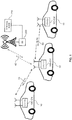
- Fig. 1 schematically illustrates an exemplary V2V communication scenario in which concepts in accordance with the illustrated embodiments may be applied.
- Fig. 1 shows a vehicles 10, each of which is equipped with a V2V communication device (V2V-CD).
- the vehicles 10, 20 may be road vehicles, such as automobiles or motorcycles, for passenger transport and/or for cargo transport.
- the illustrated V2V-CDs are assumed to form a cluster, of which the V2V-CD 100-CH acts as the CH, and the other V2V-CDs 100-CM are CMs.
- the V2V-CDs 100-CH, 100-CM support at least the above-mentioned first radio technology. At least the V2V-CD 100-CH also supports the second radio technology and may communicate with the cellular network, represented by a base station 200-1 and a control node 210.
- the BS may for example be an eNB as specified for the LTE technology.
- the control node may for example be an MME as specified for the LTE technology.
- the V2V-CDs 100-CH, 100-CM may perform V2V communication. This may include transmitting one or more V2V communication messages 50, which may then be received by one or more of the other V2V-CDs 100-CH, 100-CM, 100-CM. Moreover, it is to be understood that further vehicles equipped with corresponding V2V-CDs communication devices could be present and could send or receive such V2V communication messages, even if they are not member of this cluster. Typically, the V2V communication messages 50 are broadcast to all other V2V communication devices within the communication range of the first radio technology for the given V2V-CD.
- V2V communication messages 50 may for example correspond to CAMs as defined in ETSI TS 102637-2.
- the V2V-CD 100-CH acting as the CH communicates with the cellular network.
- the V2V-CD 100-CH may exchange messages 40 for controlling cluster management with the above mentioned network node.
- this network node corresponds to the BS 200.
- another network node within the cellular network could be used for this purpose, e.g., the control node 210.
- a network node with connectivity the cellular network could be used, e.g., a server with Internet connectivity. Communication of the other V2V-CDs 100-CM of the cluster, i.e., the CMs, with the cellular network is not required.
- Fig. 2 shows an exemplary scenario involving multiple clusters, in particular a first cluster 20 with the V2V-CDs 100-CH, 100-CM of Fig. 1 and a second cluster 20' with V2V-CDs 100-CH, 100-CM.
- the V2V-CDs of the second cluster 20' may be generally similar to that of the first cluster 20.
- the V2V-CD 100-CH' is assumed to act as the CH of the second cluster 20', and the V2V-CDs 100-CM' are assumed to be CMs of the second cluster 20'.
- the V2V-CD 100-CH' may communicate with the BS 200 to exchange messages for controlling cluster management. Also in this case, communication of the other V2V-CDs 100-CM' of the cluster, i.e., the CMs, with the cellular network is not required.
- the first and second clusters 20, 20' differ with respect to the heading, i.e., direction of movement, of the vehicles. Accordingly, the association of V2V-CDs to one of the clusters may be based on the heading of the corresponding vehicle as compared to the headings of the vehicles corresponding to the V2V-CDs of the cluster, e.g., as compared to an average heading determined for the cluster.
- the association of CMs to the cluster is managed by the CH.
- the CH may control joining of a V2V-CD to the cluster and detect leaving of a CM from the cluster.
- the CH may maintain a list of the CM identities.
- the BS 200 operates to assign sets of resources to the clusters. Specifically, the BS 200 may assign different sets of resources to different clusters, thereby avoiding collisions of V2V communication messages 50 from different clusters, in the following also referred to as inter-cluster collisions.
- the BS 200 sends a resource assignment indicating the assigned set of resources to the CH. This may be accomplished in a broadcast message, or in a unicast message directed to only the CH for which the resource assignment is intended. However, the BS 200 may also assign the same resources to different clusters, e.g., in cases where collisions of V2V communication messages 50 from the different are unlikely or not possible due to non-overlapping communication ranges of the first radio technology.
- the BS 200 may utilize information on the cluster as provided by the CH.
- the information provided by the CH may be updated regularly to take into account that the vehicles of each cluster and therefore also the cluster itself move and that the cluster size may increase by joining of new CMs or decrease by leaving of CMs.
- the BS 200 may then adjust the assignment of resource sets accordingly.
- the assignment of different resource sets may be implemented on the basis defining separate resources according to a Time Division Multiple Access (TDMA) and/or Frequency Division Multiple Access (FDMA) scheme.
- time slots could be defined for the IEEE 802.11p radio technology and allocated to different V2V communication devices.
- the duration of such time slots may be defined to be equal to 1 ms, thereby achieving a conformity with existing cellular radio technologies.
- the duration of a time slot could also be set according to the size of V2V communication messages 50 and the utilized data rate for V2V communication. For example, if the size of the V2V communication messages is 200 Byte and the data rate is 6 Mbps, a time slot size of 02667 ms could be used.
- the resource sets may be contiguous resource blocks, but also be combined from non-contiguous resources.
- the CH of the cluster may use the set of resources indicated in the resource assignment for assigning resources therefrom to the individual V2V-CDs in the cluster.
- the resource assignment may be accomplished to avoid collisions of V2V communication messages 50 from V2V-CDs within the same cluster, in the following also referred to as intra-cluster collisions.
- the CH may use information on the individual V2V-CDs of the cluster, such as heading, position, velocity, or the like.
- the CH may determine such information by evaluating V2V communication messages 50 from the other V2V-CDs of the cluster, e.g., from CAMs.
- the CH may in turn indicate the assigned resources by sending a V2V communication message 50 indicating the assigned resources.
- Fig. 3 illustrates an exemplary organization of communication phases according to an embodiment of the invention.
- the communication is organized into a broadcast phase, a random access phase, an advertisement phase for each cluster, and a dissemination phase for each cluster.
- the communication is organized into a broadcast phase, a random access phase, an advertisement phase for each cluster, and a dissemination phase for each cluster.
- four clusters are assumed to be present.
- the BS 200 broadcasts a cluster information frame over the cellular network.
- the cluster information frame can be received by each V2V-CD supporting the second radio technology and attached to the cell of the BS 200.
- the cluster information frame provides a description of each cluster having a CH in the cell of the BS 200.
- Such cluster description may for example specify the identity of the CH, a position of the cluster or CH, a heading of the cluster, e.g., in terms of heading of the CH or of an average heading, an average velocity of the cluster, a size of the cluster, e.g., in terms of the number V2V devices in the cluster, or the like.
- a V2V-CD receiving the cluster information frame may use this information for selecting a cluster for association to one of the clusters.
- the V2V-CD may decide that none of the clusters is suitable for association and decide to become the CH of a new cluster.
- a V2V-CD may send a request to a CH to join the cluster of the CH and thereby become a CM.
- a resource in particular time slot, for sending the request is chosen randomly. The risk of collisions between different requests is assumed to be low because the joining of a cluster will typically occur less frequently than for example the sending of CAM messages.
- resources to be used for the random access phase may be configured by the BS 200.
- a round with an advertisement phase and a dissemination phase is provided for each cluster.
- the CH broadcasts one or more V2V communication messages to indicate the cluster configuration and the assignment of resources to the CMs.
- V2V communication messages may also be referred to as advertisement (ADV) messages.
- the ADV messages may also indicate the cluster description and be received by V2V-CDs which are not member of the cluster. In the latter case, such V2V-CDs may decide to join the cluster, which may be accomplished without previous reception of the cluster information frame. The latter option is specifically useful for V2V-CDs without support of the second radio technology.
- the V2V-CDs of the cluster transmit V2V communication messages, in particular CAMs. This is accomplished in the resources assigned by the CH, e.g., in different time slots when using TDMA.
- the V2V communication messages may be transmitted by broadcasting so that they can be received by all other V2V communication devices in the communication range of the transmitting V2V communication device.
- the CH may also detect that a CM has left the cluster.
- the CH may detect that the CM did not send a V2V communication message in its assigned resource(s). If this occurs, or occurs for a predefined number of times, the CH may remove the CM from the list of CM identities.
- Fig. 4 illustrates exemplary processes for formation of a new cluster.
- the processes involve a first V2V-CD 100-1, a second V2V-CD 100-2, a third V2V-CD 100-3, and the BS 200.
- the processes may for example be performed when the first V2V-CD 100-1 decides that there is no suitable cluster to associate with and therefore decides to become the CH of a new cluster.
- the V2V-CD 100-1 may send message 401 over the cellular network to the BS 200.
- the V2V-CD 100-1 may request to be appointed as a CH.
- the BS 402 may send message 402 to the V2V-CD 100-1 to confirm appointment of the V2V-CD 100-1 as the CH of the new cluster.
- the message 402 may also include a resource assignment, indicating a set of resources assigned to the cluster.
- the BS 200 may then broadcast a cluster description using the second radio technology, e.g., using the above-mentioned cluster information frame.
- the cluster description is assumed to be received by the V2V-CDs 100-2, 100-3.
- the V2V-CD 100-2 may then send message 404 to the V2V-CD 100-1, to request joining of the cluster.
- the message 404 may be transmitted in the above-mentioned random access phase, without requiring previous resource assignment to the V2V-CD 100-2.
- the V2V-CD 100-1 may join the V2V-CD 100-2 to the cluster, as indicated by step 405. This may specifically involve adding the identity of the V2V-CD 100-2 to the list of CM identities maintained by the V2V-CD 100-1.
- V2V-CD 100-3 may send message 406 to the V2V-CD 100-1, using the first radio technology, to request joining of the cluster.
- the message 406 may be transmitted in the above-mentioned random access phase, without requiring previous resource assignment to the V2V-CD 100-3.
- the V2V-CD 100-1 may join the V2V-CD 100-3 to the cluster, as indicated by step 407. This may specifically involve adding the identity of the V2V-CD 100-3 to the list of CM identities maintained by the V2V-CD 100-1.
- the V2V-CD 100-1 may then send message 408 over the cellular network to the BS 200, to update the information on the cluster.
- the V2V-CD 100-1 may determine a cluster description and include this cluster description into message 408. In the illustrated example, this cluster description would indicate that the size of the cluster has increased to three.
- the BS 200 may assign a set of resources to the cluster, as indicated by step 409.
- This set of resources may differ from a previously assigned set of resources, e.g., as indicated in the message 402.
- the set of resources assigned at step 409 may include more resources to consider the increased size of the cluster.
- the BS 200 then sends message 410 to the V2V-CD 100-1.
- the message 410 includes a resource assignment indicating the set of resources as assigned at step 409.
- the V2V-CD 100-1 may assign resources to the individual V2V-CDs 100-1, 100-2, 100-3 of the cluster, as indicated by step 411. This is accomplished from the set of resources indicated in the resource assignment. For example, a corresponding time slot may be assigned to each V2V-CD 100-1, 100-2, 100-3.
- the V2V-CD 100-1 may then proceed by indicating the assigned resources to the other V2V-CDs 100-2, 100-3 of the cluster. This may be accomplished during the above-mentioned advertisement phase by broadcasting an ADV message 412 using the first radio technology.
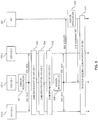
- Fig. 5 illustrates exemplary processes for management of V2V communication.
- the processes which may for example follow the cluster formation of Fig. 4 , involve the first V2V-CD 100-1, the second V2V-CD 100-2, the third V2V-CD 100-3, and the BS 200.
- the V2V-CD 100-1 is assumed to be initially appointed as the CH of a cluster further including the V2V-CD 100-2 and the V2V-CD 100-2.
- the V2V-CD 100-1 may assign resources to the individual V2V-CDs 100-1, 100-2, 100-3 of the cluster. This is accomplished from the set of resources previously indicated by the BS 200 (e.g., in the processes of Fig. 4 ). For example, a corresponding time slot may be assigned to each V2V-CD 100-1, 100-2, 100-3.
- the V2V-CD 100-1 may then proceed by indicating the assigned resources to the other V2V-CDs 100-2, 100-3 of the cluster. This may be accomplished during the above-mentioned advertisement phase by broadcasting an ADV message 502 using the first radio technology.
- each V2V-CD 100-1, 100-2, 100-3 may then broadcast a CAM, as indicated by steps 503, 504, 505. This is accomplished in the previously assigned resources, thereby avoiding collisions between the CAMs.
- the CAMs will be received by all other V2V-CDs 100-1, 100-2, 100-3 of the cluster, thereby spreading information through the cluster.
- the V2V-CD 100-1 may also receive new information on the CMs, i.e., on the V2V-CDs 100-2, 100-3, such as current position, current velocity, current heading. This information may be used by the V2V-CD 100-1 to update the cluster description.
- the V2V-CD 100-1 may assign resources to the individual V2V-CDs 100-1, 100-2, 100-3 of the cluster. This is accomplished from the set of resources previously indicated by the BS 200 (e.g., in the processes of Fig. 4 ). For example, a corresponding time slot may be assigned to each V2V-CD 100-1, 100-2, 100-3. In this case, the assignment of the resources may be based on the updated cluster description.
- the V2V-CD 100-1 may then proceed by indicating the assigned resources to the other V2V-CDs 100-2, 100-3 of the cluster. This may be accomplished during the above-mentioned advertisement phase by broadcasting an ADV message 507 using the first radio technology.
- the V2V-CD 100-1 may send message 508 over the cellular network to the BS 200, using the second radio technology, to update the information on the cluster.
- the V2V-CD 100-1 may include the newly determined cluster description into the message 508.
- this cluster description could for example indicate a new position of the cluster, a new heading of the cluster, or a new average velocity of the cluster.
- the BS 200 may assign a set of resources to the cluster, as indicated by step 509.
- This set of resources may differ from a previously assigned set of resources, e.g., as indicated in the processes of Fig. 4 .
- the set of resources assigned at step 509 may include different time slots to avoid inter-cluster collisions with another cluster which is now close to the cluster of the V2V-CDs 100-1, 100-2, 100-3.
- the BS 200 then sends message 510 to the V2V-CD 100-1.
- the message 510 includes a resource assignment indicating the set of resources as assigned at step 509.
- the BS 200 may also broadcast the cluster description using the second radio technology, e.g., in the above-mentioned cluster information frame.
- the cluster description may be received by other V2V-CDs which may use the cluster description to decide on association with the cluster.
- Fig. 6 illustrates further exemplary processes for management of V2V communication.
- the processes which may for example follow the cluster formation of Fig. 4 or the processes of Fig. 5 , involve the first V2V-CD 100-1, the second V2V-CD 100-2, the third V2V-CD 100-3, and the BS 200.
- the V2V-CD 100-1 is assumed to be initially appointed as the CH of a cluster further including the V2V-CD 100-2 and the V2V-CD 100-2.
- the V2V-CD 100-1 may assign resources to the individual V2V-CDs 100-1, 100-2, 100-3 of the cluster. This is accomplished from the set of resources previously indicated by the BS 200 (e.g., in the processes of Fig. 4 or 5 ). For example, a corresponding time slot may be assigned to each V2V-CD 100-1, 100-2, 100-3.
- the V2V-CD 100-1 may then proceed by indicating the assigned resources to the other V2V-CDs 100-2, 100-3 of the cluster. This may be accomplished during the above-mentioned advertisement phase by broadcasting an ADV message 602 using the first radio technology.
- each V2V-CD 100-1, 100-2, 100-3 could then broadcast a CAM, as indicated by steps 603, 604, 605. Similar to steps 503, 504, 505 of Fig. 5 . However, in the illustrated example it is assumed that no CAM broadcast by the V2V-CD 100-3 occurs in step 605.
- the V2V-CD 100-1 use the absence of the CAM broadcast in the resources assigned to the V2V-CD 100-3 to detect leaving of the V2V-CD 100-3 from the cluster.
- the V2V-CD 100-1 may thus remove the V2V-CD 100-3 from the cluster. This may specifically involve deleting the identity of the V2V-CD 100-3 from the list of CM identities maintained by the V2V-CD 100-1.
- the BS 200 may assign a set of resources to the cluster, as indicated by step 608.
- This set of resources may differ from a previously assigned set of resources, e.g., as indicated in the processes of Fig. 4 or 5 .
- the set of resources assigned at step 608 may include less resources to consider the decreased size of the cluster.
- the BS 200 then sends message 609 to the V2V-CD 100-1.
- the message 609 includes a resource assignment indicating the set of resources as assigned at step 608.
- the BS 200 may also broadcast the cluster description using the second radio technology, e.g., in the above-mentioned cluster information frame.
- the cluster description may be received by other V2V-CDs which may use the cluster description to decide on association with the cluster.
- Fig. 7 illustrates exemplary processes for cluster re-organization.
- the processes which may for example follow the cluster formation of Fig. 4 or the processes of Fig. 5 , involve the first V2V-CD 100-1, the second V2V-CD 100-2, the third V2V-CD 100-3, and the BS 200.
- the V2V-CD 100-1 is assumed to be initially appointed as the CH of a cluster further including the V2V-CD 100-2 and the V2V-CD 100-2.
- the processes of Fig. 7 may for example be used if the V2V-CD 100-1 determines that it is no longer suitable to act as the CH of the cluster and another V2V-CD is a more appropriate candidate. This may for example occur when merging the cluster managed by the V2V-CD 100-1 to another cluster.
- the V2V-CD 100-1 may send message 701 over the cellular network to the BS 200.
- the V2V-CD 100-1 may request to be de-appointed as a CH.
- the message 701 may also indicate a new candidate CH, e.g., the V2V-CD 100-3.
- the BS 200 may thus send message 702 to the V2V-CD 100-1 to appoint the V2V-CD 100-3 as the CH of the new cluster.
- the message 702 may also include a resource assignment, indicating a set of resources assigned to the cluster.
- the BS 200 may then broadcast the new cluster description using the second radio technology.
- the new cluster description would indicate that the V2V-CD 100-3 is the CH of the cluster.
- the BS 200 may assign a set of resources to the cluster, as indicated by step 704.
- the V2V-CDs 100-2, 100-3 are assumed to remain CMs of the cluster.
- the BS 200 then sends message 705 to the V2V-CD 100-1.
- the message 705 includes a resource assignment indicating the set of resources as assigned at step 704.
- the V2V-CD 100-1 may assign resources to the individual V2V-CDs 100-1, 100-2, 100-3 of the cluster, as indicated by step 411. This is accomplished from the set of resources indicated in the resource assignment. For example, a corresponding time slot may be assigned to each V2V-CD 100-1, 100-2, 100-3.
- the V2V-CD 100-1 may then proceed by indicating the assigned resources to the other V2V-CDs 100-2, 100-3 of the cluster. This may be accomplished during the above-mentioned advertisement phase by broadcasting an ADV message 707 using the first radio technology.
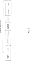
- Fig. 8 illustrates an exemplary structure of the cluster information frame, which may for example be used in messages 403, 511, 610, or 703.
- the cluster information frame may include control information, such as an identity of the node transmitting the frame (NODE ID), an indication that the frame is a cluster information frame (FRAME TYPE), a length of a payload section of the frame (PAYLOAD LENGTH), an indication of resources to be used for the random access phase (RA RESOURCES), a number of the described clusters (NUMBER OF CLUSTERS), and the cluster description(s).
- NODE ID an identity of the node transmitting the frame
- FRAME TYPE an indication that the frame is a cluster information frame
- PAYLOAD LENGTH a length of a payload section of the frame
- RA RESOURCES an indication of resources to be used for the random access phase
- NUMBER OF CLUSTERS a number of the described clusters
- This frame structure allows for flexibly adapting the frame to the number
- Each cluster description specifies an identity of the CH (CH ID), a timestamp indicating the time of generating the cluster description, the position of the cluster in terms of latitude and longitude of the CH or in terms of an average latitude and longitude, a dimension of the cluster, a velocity of the cluster, e.g., in terms of an average velocity or in terms of the velocity of the CH, a heading of the cluster, e.g., in terms of an average heading or in terms of the heading of the CH, and a size of the cluster, e.g., in terms of the number of V2V-CDs in the cluster.
- the timestamp allows for assessing the actuality of the cluster description, which may differ between different cluster descriptions included in the same cluster information frame.
- Fig. 9 illustrates an exemplary structure of an update frame, which may for example be used in messages 408, 508, or 607.
- the update frame may include control information, such as an indication that the frame is an update frame (FRAME TYPE) for indicating a new cluster description. Further, the update frame includes the cluster description.
- FRAME TYPE update frame
- the cluster description specifies an identity of the CH (CH ID), which is also the source of the update frame, the position of the cluster in terms of latitude and longitude of the CH or in terms of an average latitude and longitude, a dimension of the cluster, a velocity of the cluster, e.g., in terms of an average velocity or in terms of the velocity of the CH, a heading of the cluster, e.g., in terms of an average heading or in terms of the heading of the CH, and a size of the cluster, e.g., in terms of the number of V2V-CDs in the cluster.
- Fig. 10 illustrates an exemplary structure of a further update frame, which may for example be used in the case of appointing a new CH, in particular when merging clusters, such as in in message 701.
- the update frame may include control information, such as an indication that the frame is an update frame (FRAME TYPE) for indicating a new cluster description with a new CH.
- the frame structure is generally similar to that of Fig. 9 , but further indicates the identity of the new CH (NEW CH ID).
- the update frame may include cluster description information for the new cluster, which may be generally to those of Fig. 9 , e.g., specify the position of the cluster, a dimension of the cluster, a velocity of the cluster, a heading of the cluster, and/or a size of the cluster.
- Fig. 11 illustrates an exemplary structure of a resource request frame, which may be used as a simplified update message when a different amount of resources for V2V communication is required for the cluster, but otherwise the characteristics of the cluster remain substantially unchanged. This may for example be the case in the scenario of Fig. 6 , when a CM leaves the cluster and less resources are requierd.
- the resource request frame may then be used in message 607. Further, the resource request frame could also be used when a new CM joins the cluster and more resources are required.
- the resource request frame may include control information, such as an indication that the frame is a frame for transmitting a request (FRAME TYPE) and an indication that the request is a request for resources for V2V transmission (REQUEST TYPE).
- the resource request frame includes the identity of the CH requesting the resources (CH ID), i.e., the source of the resource request. Still further, the resource request frame indicates the size of the cluster, e.g., in terms of the number of V2V-CDs in the cluster, which information may then be used for assigning an appropriate amount of resources for V2V communication to the cluster.
- CH ID the identity of the CH requesting the resources
- the resource request frame indicates the size of the cluster, e.g., in terms of the number of V2V-CDs in the cluster, which information may then be used for assigning an appropriate amount of resources for V2V communication to the cluster.
- Fig. 12 illustrates an exemplary structure of a cluster joining request frame, which may for example be used in messages 404 or 406.
- the cluster joining request frame may include control information, such as an indication that the frame is a frame for transmitting a request (FRAME TYPE) and an indication that the request is a cluster joining request.
- the cluster joining request frame includes the identity of the CH of the cluster to be joined (CH ID), i.e., to which the cluster joining request is addressed, and an address of the requesting V2V-CD, e.g., in the form of an IPv6 (Internet Protocol Version 6) address. The latter may then be used as the CM identity.
- CH ID CH of the cluster to be joined
- IPv6 Internet Protocol Version 6
- Fig. 13 shows a flowchart for illustrating a method which may be used for implementing the above concepts in a V2V-CD with access to a cellular network, e.g., the V2V-CD 100-CH or one of the V2V-CDs 100-1, 100-2, 100-3.
- the V2V-CD is assumed to be located onboard a vehicle, e.g., a road vehicle for passenger and/or cargo transport.
- the V2V-CD is organized in a cluster with at least one further V2V-CD.
- the V2V-CD may serve as the CH of the cluster, and the at least one further V2V-CD communication device may be a CM.
- the cellular network may implement a one or more cellular radio technologies, e.g., GSM, UMTS or Wideband CDMA, CDMA2000, WiMaX, 3GPP SAE/LTE, and/or 3GPP LTE-Advanced.
- the V2V communication in particular transmission of V2V messages such as CAMs, may be implemented using a radio technology for V2V communication, which is different from such cellular radio technology, e.g., a VANET technology, such as defined by IEEE 802.11p, or LTE D2D radio technology.
- the V2V-CD manages the cluster of V2V-CDs. This may involve controlling the joining of other V2V-CDs to the cluster or detecting of leaving of a V2V-CD from the cluster. Also, the V2V-CD may maintain a list of V2V-CDs of the cluster, e.g., a list of CM identities.
- the V2V-CD determines a cluster description.
- the cluster description specifies on or more characteristics of the cluster. For example, such characteristics may include a size of the cluster, e.g., in terms of the number of V2V-CDs in the cluster, a position of the cluster, e.g., in terms of geographical latitude and longitude, averaged over the cluster or represented by the position of the CH. Further, such characteristics may include a velocity of the cluster, averaged over the cluster or represented by the velocity of the CH, and/or a heading of the cluster, averaged over the cluster or represented by the heading of the CH.
- the V2V-CD sends the cluster description to a network node.
- the network node may be a node of the cellular network, e.g., a BS such as an eNB or a control node such as an MME.
- the network node may also be connected to the cellular network, e.g., over the Internet.
- the cluster description may for example be sent in an update message, such as message 408, 508, 607, or 701.
- a frame structure as illustrated in Fig. 9 , 10 , or 11 may be used for sending the cluster description.
- the network node receives a resource assignment from the network node. This is accomplished over the cellular network.
- the resource assignment indicates a set of resources for V2V communication assigned to the cluster, e.g., in terms of time slots.
- the network node assigns resources from the indicated set of resources to the V2V-CDs of the cluster. This may be accomplished on the basis of information on these V2V-CDs, e.g., position, heading, velocity.
- the network node indicates the assigned resources to the other V2V-CDs of the cluster using the radio technology for V2V communication., e.g., in an ADV message as explained for messages 412, 502, 507, 602, 607, or 707.
- the V2V-CDs of the cluster may then use the assigned resources for broadcasting V2V messages, in particular CAMs.
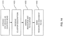
- Fig. 14 shows a flowchart for illustrating a method which may be used for implementing the above concepts in a network node, e.g., a node of the cellular network itself, e.g., a base station, or a node connected to the cellular network.
- the method may be used for controlling V2V communication as performed by V2V-CDs which are organized into clusters.
- the V2V-CDs are assumed to be each located onboard a vehicle, e.g., a road vehicle for passenger and/or cargo transport.
- the network node may be a node of the cellular network, e.g., a BS such as an eNB or a control node such as an MME.
- the network node may also be connected to the cellular network, e.g., over the Internet.
- the cellular network may implement a one or more cellular radio technologies, e.g., GSM, UMTS or Wideband CDMA, CDMA2000, WiMaX, 3GPP SAE/LTE, and/or 3GPP LTE-Advanced.
- the V2V communication in particular transmission of V2V messages such as CAMs, may be implemented using a radio technology for V2V communication, which is different from such cellular radio technology, e.g., a VANET technology, such as defined by IEEE 802.11p, or LTE D2D radio technology.
- the network node may appoint a V2V-CD as a CH of a cluster.
- the cluster includes this V2V-CD and at least one further V2V-CD.
- the V2V-CD manages the cluster of V2V-CDs. This may involve controlling the joining of other V2V-CDs to the cluster or detecting of leaving of a V2V-CD from the cluster.
- the V2V-CD may maintain a list of V2V-CDs of the cluster, e.g., a list of CM identities.
- the network node receives a cluster description from the V2V-CD. This is accomplished over the cellular network.
- the cluster description specifies on or more characteristics of the cluster. For example, such characteristics may include a size of the cluster, e.g., in terms of the number of V2V-CDs in the cluster, a position of the cluster, e.g., in terms of geographical latitude and longitude, averaged over the cluster or represented by the position of the CH. Further, such characteristics may include a velocity of the cluster, averaged over the cluster or represented by the velocity of the CH, and/or a heading of the cluster, averaged over the cluster or represented by the heading of the CH.
- the cluster description may for example be received in an update message, such as message 408, 508, 607, or 701.
- a frame structure as illustrated in Fig. 9 , 10 , or 11 may be used for transmitting the cluster description.
- the network node assigns a set of resources to the cluster. This is accomplished on the basis of the received cluster description. In this way inter-cluster collisions of V2V messages may be avoided in an efficient manner, an spatial reuse of resources becomes possible.
- the network node sends a resource assignment to the V2V-CD. This is accomplished over the cellular network.
- the resource assignment indicates the set of resources as assigned at step 1430.
- Figs. 13 and 14 may be combined with each other, e.g., in a system including the V2V-CD managing the cluster according to the method of Fig. 13 and the network node interacting with this V2V-CD according to the method of Fig. 14 .
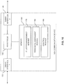
- Fig. 15 illustrates an exemplary implementation of a V2V-CD.
- the V2V-CD may for example correspond to the above V2V-CD 100-CH or 100-1.
- the V2V communication device may be mounted onboard a vehicle, e.g., a road vehicle for passenger and/or cargo transport.
- the V2V-CD includes a first radio interface 130 for communication with one or more other V2V-CDs.
- this communication may utilize a VANET technology in accordance with IEEE 802.11p or other radio technology for V2V communication, e.g., based on the LTE D2D radio technology.
- the V2V-CD includes a second radio interface 140 for communication with a cellular network.
- the cellular network may support one or more cellular network radio technologies, e.g., GSM, UMTS or Wideband CDMA, CDMA2000, LTE, and/or LTE-Advanced.
- the V2V-CD includes one or more processor(s) 150 coupled to the interfaces 130, 140 and a memory 160 coupled to the processor 150.
- the memory 160 may include a read-only memory (ROM), e.g., a flash ROM, a random-access memory (RAM), e.g., a dynamic RAM (DRAM) or static RAM (SRAM), a mass storage, e.g., a hard disk or solid state disk, or the like.
- ROM read-only memory
- RAM random-access memory
- DRAM dynamic RAM
- SRAM static RAM
- the memory 160 includes suitably configured program code modules to be executed by the processor(s) 150 so as to implement the above-described functionalities of the V2V-CD.
- the program code modules in the memory 160 may include a cluster management module 170 so as to implement the above-described functionalities of managing a cluster of V2V-CDs and providing cluster descriptions. Further, the program code modules in the memory 160 may also include a resource assignment module 180 so as to implement the above-mentioned functionalities for assigning resources to V2V-CDs of the managed cluster. Still further, the program code modules in the memory 160 may also include a control module 190 so as to implement general control functionalities, such as sending a and generating messages and controlling the radio interfaces.
- the structure as illustrated in Fig. 15 is merely schematic and that the V2V communication device may actually include further components which, for the sake of clarity, have not been illustrated, e.g., further interfaces such as an interface with respect to vehicle systems.
- the memory 160 may include further types of program code modules, which have not been illustrated, e.g., program code modules for implementing known functionalities of a V2V-CD.
- a computer program may be provided for implementing functionalities of the V2V communication device, e.g., in the form of a physical medium storing one or more of the program code modules to be stored in the memory 160 or by making one or more of the program code modules available for download.
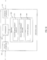
- Fig. 16 illustrates an exemplary implementation of a network node.
- the node may correspond to a base station of a cellular network, e.g., to an eNB.
- similar functionalities could also be implemented in other network nodes of the cellular network, e.g., in control nodes of the cellular network, such as an MME, or even in network nodes with connectivity to the cellular network, e.g., a server with Internet connectivity.
- the network node may be configured to assign sets of resources to clusters of V2V-CDs and to indicate a corresponding resource assignment to a V2V-CD serving as the CH.
- V2V-CD is responsible for otherwise managing the cluster, e.g., controlling joining or leaving of other V2V-CDs from the cluster.
- V2V communication by the V2V communication devices of the cluster may utilize a VANET technology, e.g., in accordance with IEEE 802.11p, or based on the LTE D2D radio technology.
- the node includes a device interface 230 for communication with one or more V2V communication devices connected to the cellular network
- the node may include a network interface 240 for communication with other nodes of the cellular network. If the node implements a base station of the cellular network, the device interface may correspond to a radio interface based on a radio technology supported by the cellular network. If the node implements a control node of the cellular network, the device interface may provide a direct or indirect connection to one or more base stations of the cellular network, which in turn may provide a radio interface to one or more V2V communication devices.
- the node includes one or more processor(s) 250 coupled to the interfaces 230, 240 and a memory 260 coupled to the processor 250.
- the memory 260 may include a ROM, e.g., a flash ROM, a RAM, e.g., a DRAM or SRAM, a mass storage, e.g., a hard disk or solid state disk, or the like.
- the memory 260 includes suitably configured program code modules to be executed by the processor(s) 250 so as to implement the above-described functionalities for providing one or more V2V communication devices with channel information for V2V communication.
- the program code modules in the memory 260 may include a cluster management module 270 for handling cluster information provided by one or more CHs and for appointing CHs. Further, the program code modules in the memory 160 may also include a resource assignment module 280 so as to implement the above-mentioned functionalities for assigning a set resources to one or more clusters. Still further, the program code modules in the memory 260 may also include a control module 290 so as to implement general control functionalities, such as sending a and generating messages and controlling the radio interfaces.
- the structure as illustrated in Fig. 16 is merely schematic and that the node may actually include further components which, for the sake of clarity, have not been illustrated, e.g., further interfaces.
- the memory 260 may include further types of program code modules, which have not been illustrated, e.g., program code modules for implementing known functionalities of a base station, such as an eNB, or control node, such as an MME.
- a computer program may be provided for implementing functionalities of the V2V communication device, e.g., in the form of a physical medium storing one or more of the program code modules to be stored in the memory 260 or by making one or more of the program code modules available for download.
- V2V both inter-cluster and intra-cluster collisions of V2V communication messages may be avoided.
- V2V-CDs without support for cellular network communication may join a cluster.
- the above concepts may be implemented by using correspondingly designed software to be executed by one or more processors of an existing device, or by using dedicated device hardware.
- the nodes as described herein may be implemented by a single device or by multiple devices, e.g., a device cloud or system of cooperating devices.
Description
- The present invention relates to methods for controlling vehicle-to-vehicle communication and to corresponding devices.
- In vehicular transport and traffic management, it is known to use Intelligent Transport System (ITS) applications for supporting drivers. In this way, traffic safety can be improved by providing the drivers with information which allows for making smarter decisions. Such ITS applications may involve transmitting information between different vehicles, e.g., in the form of a Cooperative Awareness Message (CAM). The information may be used for providing a warning or guidance to the driver, e.g., in the form of an emergency vehicle warning, an intersection collision warning, a slow vehicle warning, or a motorcycle approaching indication. The information may be transmitted using a radio technology for vehicle-to-vehicle (V2V) communication, e.g., as specified by the IEEE 802.11p standard, also referred to as WAVE (Wireless Access in Vehicular Environments). According to the IEEE 802.11p standard, a wireless ad-hoc network may be formed between different vehicles. Such ad-hoc networks are also referred to as Vehicular Ad-Hoc Network (VANET).
- CAMs are messages which are typically periodically broadcast by a vehicle to inform nearby vehicles about the current status of the vehicle. CAMs may for example be used for transmitting the current geographical position, speed, and/or basic attributes of the vehicle. A vehicle may receive CAMs from other vehicles and utilize the information provided in the CAMs for supporting its operator, e.g., by providing a warning or other guidance.
- More details on CAMs can be found in ETSI TS 102 637-3 "Intelligent Transport Systems (ITS); Vehicular Communications; Basic Set of Applications; Part 2: Specification of Cooperative Awareness Basic Service". Here, a generation of cooperative applications is described, which are based on the IEEE 802.11p specifications. The traffic model for the transmission of such CAM messages is specified to use periodic broadcast traffic consisting of approx. 500 payload bytes with a repetition rate 5-10 Hz and event-driven broadcast traffic consisting of approx. 500 payload bytes. Both traffic types may exist at the same time.
- The ad-hoc network according to IEEE 802.11p is a contention based system, in which different V2V communication devices compete for access to the same radio channel. Accordingly, there is also a risk of colliding access attempts by different V2V communication devices. Such collisions may in turn result in delays until a V2V communication device successfully gains access to the radio channel.
- In "LTE4V2X: LTE for a Centralized VANET Organization" by G. Remy et al., IEEE Globecom Proceedings (2011), it is proposed to use infrastructure of a cellular network to organize a VANET into clusters of V2V communication devices. In this case, the cellular network is based on the LTE (Long Term Evolution) technology specified by 3GPPP (3rd Generation Partnership Project). In particular, it is described that a base station of the cellular network, referred to as eNodeB (eNB), may organize a cluster formed of a cluster head (CH) and cluster members (CMs). Over the cellular network, the eNB receives Floating Car Data (FCD) from multiple V2V communication devices and uses this information to elect the CH and associate the CMs to the cluster. The eNB then broadcasts a cluster description over the cellular network. The cluster description indicates the identity of the CH and the identities of the CMs. By receiving such cluster description, a V2V communication device is informed about the cluster to which it is assigned.
- Within the cluster, the CH acts as a gateway between the CMs and the cellular network. Specifically, the CH aggregates FCD transmitted by the CMs over the VANET and sends the aggregated FCD data over the cellular network to the eNB. For the VANET communication within the cluster, Time Division Multiple Access (TDMA) is used by the CMs. Specifically, each CM uses a different time slot, derived from the order of the identities of the CMs in the cluster description.
- However, the above LTE4V2X solution is not optimized for transmission of CAMs between V2V communication devices. Rather, the VANET communication mainly consists in communication of FCD from the CMs to the CH. In the case of CAMs it is in turn desired that typically all V2V communication devices within a certain communication range can receive the CAMs. This may in turn cause collisions of CAM transmissions. In the LTE4V2X solution, collisions between VANET transmissions within a cluster can be avoided. However, collisions between VANET transmissions of different clusters are not addressed. Still further, the centralized management of the clusters may cause significant load on the cellular network and requires cellular connectivity for each V2V communication device.
- Accordingly, there is a need for techniques which allow for efficiently utilizing a cellular network for management of V2V communication over a VANET.
- The invention provides a method in accordance with appended
claim 1, a device in accordance with appended claim 6, a system in accordance with appended claim 8 and a computer program in accordance with appended claim 9. Further embodiments of the invention are provided in accordance with appended method claims 2-5 and device claim 7, respectively. - According to an example, a method of controlling V2V communication is provided. According to the method, a V2V device manages a cluster comprising the V2V communication device and at least one further V2V communication device. The V2V communication device determines a cluster description specifying one or more characteristics of the cluster. The V2V communication device sends the cluster description over a cellular network to a network node. Further, the V2V communication device receives a resource assignment over the cellular network from the network node. The resource assignment indicates a set of resources for V2V communication assigned to the cluster. The V2V communication device assigns resources from the set of resources to the V2V communication devices of the cluster, and the V2V communication device indicates the assigned resources to the at least one further V2V communication device of the cluster.
- According to a further example, a method for controlling V2V communication is provided. According to the method, a network node receives a cluster description over a cellular network from a V2V communication device. The cluster description specifies one or more characteristics of a cluster comprising the V2V communication device and at least one further V2V communication device. On the basis of the received cluster description, the network node assigns to the cluster a set of resources for V2V communication, and sends a resource assignment over the cellular network to the V2V communication device. The resource assignment indicates the assigned set of resources.
- According to a further example, a V2V communication device is provided. The V2V device comprises a first radio interface for V2V communication with one or more other V2V communication devices, and a second radio interface for communication over a cellular network with a network node. Further, the V2V device comprises at least one processor. The at least one processor is configured to manage a cluster comprising the V2V communication device and at least one of the other V2V communication devices. Further, the at least one processor is configured to determine a cluster description specifying one or more characteristics of the cluster and to indicate the cluster description over the cellular network to the network node. Further, the at least one processor is configured to receive a resource assignment over the cellular network from the network node. The resource assignment indicates a set of resources for V2V communication assigned to the cluster. Further, the at least one processor is configured to assign resources from the set of resources to the V2V communication devices of the cluster, and to indicate the assigned resources to the at least one further V2V communication device of the cluster.
- According to a further example, a network node is provided. The network node comprises an interface for communication over a cellular network with a V2V communication device. Further, the network node comprises at least one processor. The at least one processor is configured to receive a cluster description over the cellular network from the V2V communication device. The cluster description specifies one or more characteristics of a cluster comprising the V2V communication device and at least one further V2V communication device. Further, the at least one processor is configured to assign to the cluster, on the basis of the received cluster description, a set of resources for V2V communication, and to send a resource assignment to the V2V communication device. The resource assignment indicates the assigned set of resources.
- According to a further example, a system is provided. The system comprises a V2V communication device and a network node. The V2V communication device is configured to manage a cluster comprising the V2V communication device and at least one further V2V communication device. Further, the V2V communication device is configured to determine a cluster description specifying one or more characteristics of the cluster and to indicate the cluster description over a cellular network to the network node. The network node is configured to receive the cluster description over the cellular network from the V2V communication device. Further, the network node is configured to assign to the cluster, on the basis of the received cluster description, a set of resources for V2V communication and to send a resource assignment over the cellular network to the V2V communication device. The resource assignment indicates the assigned set of resources. The V2V communication device is configured to receive the resource assignment over the cellular network from the network node. Further, the V2V communication device is configured to assign resources from the set of resources to the V2V communication devices of the cluster, and to indicate the assigned resources to the at least one further V2V communication device of the cluster.
- According to a further example, a computer program is provided. The computer program comprises program code to be executed by at least one processor of a V2V communication device. Execution of the program code thereby causes the V2V communication device to manage a cluster comprising the V2V communication device and at least one further V2V communication device. Further, execution of the program code causes the V2V communication device to determine a cluster description specifying one or more characteristics of the cluster and to indicate the cluster description over a cellular network to a network node. Further, execution of the program code causes the V2V communication device to receive a resource assignment over the cellular network from the network node. The resource assignment indicates a set of resources for V2V communication assigned to the cluster. Further, execution of the program code causes the V2V communication device to assign resources from the set of resources to the V2V communication devices of the cluster, and to indicate the assigned resources to the at least one further V2V communication device of the cluster.
- According to a further example, a computer program is provided. The computer program comprises program code to be executed by at least one processor of a network node. Execution of the program code causes the network node to receive a cluster description over a cellular network from a V2V communication device. Further, execution of the program code causes the network node to assign to the cluster, on the basis of the received cluster description, a set of resources for V2V communication and to send a resource assignment over the cellular network to the V2V communication device. The resource assignment indicates the assigned set of resources.
-
-
Fig. 1 schematically illustrates a V2V communication scenario in which concepts according to an embodiment of the invention may be applied. -
Fig. 2 schematically illustrates an exemplary scenario involving multiple clusters. -
Fig. 3 illustrates an exemplary organization of communication phases according to an embodiment of the invention. -
Fig. 4 shows a signalling diagram for illustrating exemplary processes for cluster formation according to an embodiment of the invention. -
Fig. 5 shows a signalling diagram for illustrating exemplary processes for V2V communication management according to an embodiment of the invention. -
Fig. 6 shows a signalling diagram for illustrating further exemplary processes for V2V communication management according to an embodiment of the invention. -
Fig. 7 shows a signalling diagram for illustrating exemplary processes for cluster re-organization according to an embodiment of the invention. -
Fig. 8 shows an example of a cluster information frame according to an embodiment of the invention. -
Fig. 9 shows an example of an update frame according to an embodiment of the invention. -
Fig. 10 shows an example of a further update frame according to an embodiment of the invention, which may be used the case of merging clusters. -
Fig. 11 shows an example of a resource request frame according to an embodiment of the invention, which may be used when a cluster requires more or less resources for V2V communication. -
Fig. 12 shows an example of a cluster joining request according to an embodiment of the invention. -
Fig. 13 shows a flowchart for illustrating a method according to an embodiment of the invention. -
Fig. 14 shows a flowchart for illustrating a further method according to an embodiment of the invention -
Fig. 15 schematically illustrates a V2V communication device according to an embodiment of the invention. -
Fig. 16 schematically illustrates a network node according to an embodiment of the invention. - In the following, concepts according to embodiments of the invention will be explained in more detail by referring to the accompanying drawings. The illustrated concepts relate to controlling V2V communication between vehicle-based V2V communication devices. The V2V communication may be used to implement an ITS application, e.g., based on the transmission of CAMs between vehicles.
- In the illustrated concepts, it is assumed that V2V communication is based on one or more radio technologies, e.g., an ad-hoc WLAN (Wireless Local Area Network) according to IEEE 802.11p, or LTE Device-to-Device (D2D), and that at least some of the V2V communication devices are further provided with access to a cellular network, e.g., as specified by 3GPP (Third Generation Partnership Project) or by 3GPP2. The cellular network may implement one or more radio technologies, such as GSM (Global System for Mobile communication), UMTS (Universal Terrestrial Mobile Telecommunications System) or Wideband CDMA (Code Division Multiple Access), CDMA2000, WiMaX, 3GPP SAE/LTE (Service Architecture Evolution / Long Term Evolution), and/or 3GPP LTE-Advanced. Accordingly, a V2V communication device as used in the illustrated concepts typically supports at least two different radio technologies: a first radio technology for performing V2V communication over a VANET, and a second radio technology for accessing the cellular network. However, some V2V communication devices may also support only the first radio technology.
- The cellular network may comprise several network nodes which control communication with UEs. For example, the SAE/LTE architecture typically includes base stations, referred to as eNB, and Mobility Management Entities (MMEs). For other radio technologies of the cellular network, similar types of nodes may be provided. In the scenarios as discussed in the following, such UEs which may communicate via the cellular network also include V2V communication devices.
- In the illustrated concepts, the V2V communication is organized in clusters of V2V communication devices. Each cluster includes a V2V communication device acting as a cluster head (CH), and typically also one or more other V2V communication devices, referred to as cluster member (CM). At least the CH supports also the second radio technology for accessing the cellular network. The CMs may in turn support only the first radio technology.
- To avoid collisions between V2V communication messages of an ITS application, e.g., between CAMs, the illustrated concepts involve assigning resources to a given V2V communication device, which are then used by this V2V communication device for sending V2V communication messages. Such resources can be time and/or frequency resources of the IEEE 802.11p radio technology or may be time and/or frequency resources in the radio spectrum assigned to the cellular network, e.g., of the LTE spectrum when for example using the LTE D2D radio technology. This assignment of resources is organized in two levels: On a first level sets of resources are assigned to clusters of V2V devices. This is accomplished by a network node, e.g., an eNB, MME, or some other network node which can communicate over the cellular network, e.g., a server implementing an application for controlling V2V communication. On a second level, resources from these sets are assigned to the individual V2V communication devices. This is accomplished by a V2V communication device of the cluster, referred to as cluster head (CH).
-
Fig. 1 schematically illustrates an exemplary V2V communication scenario in which concepts in accordance with the illustrated embodiments may be applied. By way of example,Fig. 1 shows avehicles 10, each of which is equipped with a V2V communication device (V2V-CD). Thevehicles - The V2V-CDs 100-CH, 100-CM support at least the above-mentioned first radio technology. At least the V2V-CD 100-CH also supports the second radio technology and may communicate with the cellular network, represented by a base station 200-1 and a
control node 210. The BS may for example be an eNB as specified for the LTE technology. The control node may for example be an MME as specified for the LTE technology. - Using the first radio technology, the V2V-CDs 100-CH, 100-CM may perform V2V communication. This may include transmitting one or more
V2V communication messages 50, which may then be received by one or more of the other V2V-CDs 100-CH, 100-CM, 100-CM. Moreover, it is to be understood that further vehicles equipped with corresponding V2V-CDs communication devices could be present and could send or receive such V2V communication messages, even if they are not member of this cluster. Typically, theV2V communication messages 50 are broadcast to all other V2V communication devices within the communication range of the first radio technology for the given V2V-CD. Further, it is possible to utilize forwarding of receivedV2V communication messages 50, thereby forming a multi-hop mesh type network of V2V communication devices. TheV2V communication messages 50 may for example correspond to CAMs as defined in ETSI TS 102637-2. - As further illustrated, the V2V-CD 100-CH acting as the CH communicates with the cellular network. Specifically, the V2V-CD 100-CH may exchange
messages 40 for controlling cluster management with the above mentioned network node. In the following, it will be assumed that this network node corresponds to theBS 200. However, also another network node within the cellular network could be used for this purpose, e.g., thecontrol node 210. Still further, also a network node with connectivity the cellular network could be used, e.g., a server with Internet connectivity. Communication of the other V2V-CDs 100-CM of the cluster, i.e., the CMs, with the cellular network is not required. -
Fig. 2 shows an exemplary scenario involving multiple clusters, in particular afirst cluster 20 with the V2V-CDs 100-CH, 100-CM ofFig. 1 and a second cluster 20' with V2V-CDs 100-CH, 100-CM. The V2V-CDs of the second cluster 20' may be generally similar to that of thefirst cluster 20. The V2V-CD 100-CH' is assumed to act as the CH of the second cluster 20', and the V2V-CDs 100-CM' are assumed to be CMs of the second cluster 20'. As in thefirst cluster 20, the V2V-CD 100-CH' may communicate with theBS 200 to exchange messages for controlling cluster management. Also in this case, communication of the other V2V-CDs 100-CM' of the cluster, i.e., the CMs, with the cellular network is not required. - In the example of
Fig. 2 , the first andsecond clusters 20, 20' differ with respect to the heading, i.e., direction of movement, of the vehicles. Accordingly, the association of V2V-CDs to one of the clusters may be based on the heading of the corresponding vehicle as compared to the headings of the vehicles corresponding to the V2V-CDs of the cluster, e.g., as compared to an average heading determined for the cluster. Other characteristics of the cluster may be used as well for the cluster association, e.g., position of the cluster, such as in terms of geographical latitude and longitude of the CH, dimension of the cluster, e.g., in terms of its length parallel to the heading direction and its width perpendicular thereto, the size of the cluster, e.g., in terms of the number of V2V-CDs in the cluster, or an average velocity of the vehicles corresponding to the V2V-CDs in the cluster. The association of CMs to the cluster is managed by the CH. In particular, the CH may control joining of a V2V-CD to the cluster and detect leaving of a CM from the cluster. For this purpose, the CH may maintain a list of the CM identities. - As mentioned above, the
BS 200 operates to assign sets of resources to the clusters. Specifically, theBS 200 may assign different sets of resources to different clusters, thereby avoiding collisions ofV2V communication messages 50 from different clusters, in the following also referred to as inter-cluster collisions. TheBS 200 sends a resource assignment indicating the assigned set of resources to the CH. This may be accomplished in a broadcast message, or in a unicast message directed to only the CH for which the resource assignment is intended. However, theBS 200 may also assign the same resources to different clusters, e.g., in cases where collisions ofV2V communication messages 50 from the different are unlikely or not possible due to non-overlapping communication ranges of the first radio technology. For this purpose, theBS 200 may utilize information on the cluster as provided by the CH. As a result, inter-cluster collisions can be avoided while at the same time allowing efficient resource usage, e.g., due to spatially separated reuse of resources by different clusters. The information provided by the CH may be updated regularly to take into account that the vehicles of each cluster and therefore also the cluster itself move and that the cluster size may increase by joining of new CMs or decrease by leaving of CMs. TheBS 200 may then adjust the assignment of resource sets accordingly. - The assignment of different resource sets may be implemented on the basis defining separate resources according to a Time Division Multiple Access (TDMA) and/or Frequency Division Multiple Access (FDMA) scheme. For example, time slots could be defined for the IEEE 802.11p radio technology and allocated to different V2V communication devices. The duration of such time slots may be defined to be equal to 1 ms, thereby achieving a conformity with existing cellular radio technologies. In some implementations, the duration of a time slot could also be set according to the size of
V2V communication messages 50 and the utilized data rate for V2V communication. For example, if the size of the V2V communication messages is 200 Byte and the data rate is 6 Mbps, a time slot size of 02667 ms could be used. The resource sets may be contiguous resource blocks, but also be combined from non-contiguous resources. - The CH of the cluster may use the set of resources indicated in the resource assignment for assigning resources therefrom to the individual V2V-CDs in the cluster. In this case, the resource assignment may be accomplished to avoid collisions of
V2V communication messages 50 from V2V-CDs within the same cluster, in the following also referred to as intra-cluster collisions. For this purpose, the CH may use information on the individual V2V-CDs of the cluster, such as heading, position, velocity, or the like. The CH may determine such information by evaluatingV2V communication messages 50 from the other V2V-CDs of the cluster, e.g., from CAMs. The CH may in turn indicate the assigned resources by sending aV2V communication message 50 indicating the assigned resources. -
Fig. 3 illustrates an exemplary organization of communication phases according to an embodiment of the invention. In the illustrated example, the communication is organized into a broadcast phase, a random access phase, an advertisement phase for each cluster, and a dissemination phase for each cluster. In the example, four clusters are assumed to be present. - In the broadcast phase, the
BS 200 broadcasts a cluster information frame over the cellular network. The cluster information frame can be received by each V2V-CD supporting the second radio technology and attached to the cell of theBS 200. The cluster information frame provides a description of each cluster having a CH in the cell of theBS 200. Such cluster description may for example specify the identity of the CH, a position of the cluster or CH, a heading of the cluster, e.g., in terms of heading of the CH or of an average heading, an average velocity of the cluster, a size of the cluster, e.g., in terms of the number V2V devices in the cluster, or the like. A V2V-CD receiving the cluster information frame may use this information for selecting a cluster for association to one of the clusters. Alternatively, the V2V-CD may decide that none of the clusters is suitable for association and decide to become the CH of a new cluster. - In the random access phase, a V2V-CD may send a request to a CH to join the cluster of the CH and thereby become a CM. A resource , in particular time slot, for sending the request is chosen randomly. The risk of collisions between different requests is assumed to be low because the joining of a cluster will typically occur less frequently than for example the sending of CAM messages. In some implementations, resources to be used for the random access phase may be configured by the
BS 200. - After the random access phase a round with an advertisement phase and a dissemination phase is provided for each cluster. In the advertisement phase the CH broadcasts one or more V2V communication messages to indicate the cluster configuration and the assignment of resources to the CMs. Such messages may also be referred to as advertisement (ADV) messages. The ADV messages may also indicate the cluster description and be received by V2V-CDs which are not member of the cluster. In the latter case, such V2V-CDs may decide to join the cluster, which may be accomplished without previous reception of the cluster information frame. The latter option is specifically useful for V2V-CDs without support of the second radio technology.
- In the dissemination phase, the V2V-CDs of the cluster transmit V2V communication messages, in particular CAMs. This is accomplished in the resources assigned by the CH, e.g., in different time slots when using TDMA. The V2V communication messages may be transmitted by broadcasting so that they can be received by all other V2V communication devices in the communication range of the transmitting V2V communication device.
- In the dissemination phase, the CH may also detect that a CM has left the cluster. In particular, the CH may detect that the CM did not send a V2V communication message in its assigned resource(s). If this occurs, or occurs for a predefined number of times, the CH may remove the CM from the list of CM identities.
-
Fig. 4 illustrates exemplary processes for formation of a new cluster. The processes involve a first V2V-CD 100-1, a second V2V-CD 100-2, a third V2V-CD 100-3, and theBS 200. The processes may for example be performed when the first V2V-CD 100-1 decides that there is no suitable cluster to associate with and therefore decides to become the CH of a new cluster. - Using the second radio technology, the V2V-CD 100-1 may send
message 401 over the cellular network to theBS 200. Bymessage 401, the V2V-CD 100-1 may request to be appointed as a CH. Upon receivingmessage 401, theBS 402 may sendmessage 402 to the V2V-CD 100-1 to confirm appointment of the V2V-CD 100-1 as the CH of the new cluster. Themessage 402 may also include a resource assignment, indicating a set of resources assigned to the cluster. - As indicated by
step 403, theBS 200 may then broadcast a cluster description using the second radio technology, e.g., using the above-mentioned cluster information frame. In the illustrated example, the cluster description is assumed to be received by the V2V-CDs 100-2, 100-3. - Using the first radio technology, the V2V-CD 100-2 may then send
message 404 to the V2V-CD 100-1, to request joining of the cluster. Themessage 404 may be transmitted in the above-mentioned random access phase, without requiring previous resource assignment to the V2V-CD 100-2. - In response to receiving the
message 404, the V2V-CD 100-1 may join the V2V-CD 100-2 to the cluster, as indicated bystep 405. This may specifically involve adding the identity of the V2V-CD 100-2 to the list of CM identities maintained by the V2V-CD 100-1. - Similarly, V2V-CD 100-3 may send
message 406 to the V2V-CD 100-1, using the first radio technology, to request joining of the cluster. Themessage 406 may be transmitted in the above-mentioned random access phase, without requiring previous resource assignment to the V2V-CD 100-3. - In response to receiving the
message 406, the V2V-CD 100-1 may join the V2V-CD 100-3 to the cluster, as indicated bystep 407. This may specifically involve adding the identity of the V2V-CD 100-3 to the list of CM identities maintained by the V2V-CD 100-1. - Using the second radio technology, the V2V-CD 100-1 may then send
message 408 over the cellular network to theBS 200, to update the information on the cluster. For this purpose, the V2V-CD 100-1 may determine a cluster description and include this cluster description intomessage 408. In the illustrated example, this cluster description would indicate that the size of the cluster has increased to three. - On the basis of the cluster description received with the
message 408, theBS 200 may assign a set of resources to the cluster, as indicated bystep 409. This set of resources may differ from a previously assigned set of resources, e.g., as indicated in themessage 402. For example, the set of resources assigned atstep 409 may include more resources to consider the increased size of the cluster. - The
BS 200 then sendsmessage 410 to the V2V-CD 100-1. Themessage 410 includes a resource assignment indicating the set of resources as assigned atstep 409. - Having received the
message 410, the V2V-CD 100-1 may assign resources to the individual V2V-CDs 100-1, 100-2, 100-3 of the cluster, as indicated bystep 411. This is accomplished from the set of resources indicated in the resource assignment. For example, a corresponding time slot may be assigned to each V2V-CD 100-1, 100-2, 100-3. - The V2V-CD 100-1 may then proceed by indicating the assigned resources to the other V2V-CDs 100-2, 100-3 of the cluster. This may be accomplished during the above-mentioned advertisement phase by broadcasting an
ADV message 412 using the first radio technology. -
Fig. 5 illustrates exemplary processes for management of V2V communication. The processes, which may for example follow the cluster formation ofFig. 4 , involve the first V2V-CD 100-1, the second V2V-CD 100-2, the third V2V-CD 100-3, and theBS 200. In the processes ofFig. 5 , the V2V-CD 100-1 is assumed to be initially appointed as the CH of a cluster further including the V2V-CD 100-2 and the V2V-CD 100-2. - As illustrated by
step 501, the V2V-CD 100-1 may assign resources to the individual V2V-CDs 100-1, 100-2, 100-3 of the cluster. This is accomplished from the set of resources previously indicated by the BS 200 (e.g., in the processes ofFig. 4 ). For example, a corresponding time slot may be assigned to each V2V-CD 100-1, 100-2, 100-3. - The V2V-CD 100-1 may then proceed by indicating the assigned resources to the other V2V-CDs 100-2, 100-3 of the cluster. This may be accomplished during the above-mentioned advertisement phase by broadcasting an
ADV message 502 using the first radio technology. - Using the first radio technology, each V2V-CD 100-1, 100-2, 100-3 may then broadcast a CAM, as indicated by
steps - In
step 506, the V2V-CD 100-1 may assign resources to the individual V2V-CDs 100-1, 100-2, 100-3 of the cluster. This is accomplished from the set of resources previously indicated by the BS 200 (e.g., in the processes ofFig. 4 ). For example, a corresponding time slot may be assigned to each V2V-CD 100-1, 100-2, 100-3. In this case, the assignment of the resources may be based on the updated cluster description. - The V2V-CD 100-1 may then proceed by indicating the assigned resources to the other V2V-CDs 100-2, 100-3 of the cluster. This may be accomplished during the above-mentioned advertisement phase by broadcasting an
ADV message 507 using the first radio technology. - Further, the V2V-CD 100-1 may send
message 508 over the cellular network to theBS 200, using the second radio technology, to update the information on the cluster. For this purpose, the V2V-CD 100-1 may include the newly determined cluster description into themessage 508. In the illustrated example, this cluster description could for example indicate a new position of the cluster, a new heading of the cluster, or a new average velocity of the cluster. - On the basis of the cluster description received with the
message 508, theBS 200 may assign a set of resources to the cluster, as indicated bystep 509. This set of resources may differ from a previously assigned set of resources, e.g., as indicated in the processes ofFig. 4 . For example, the set of resources assigned atstep 509 may include different time slots to avoid inter-cluster collisions with another cluster which is now close to the cluster of the V2V-CDs 100-1, 100-2, 100-3. - The
BS 200 then sendsmessage 510 to the V2V-CD 100-1. Themessage 510 includes a resource assignment indicating the set of resources as assigned atstep 509. - As indicated by
step 511, theBS 200 may also broadcast the cluster description using the second radio technology, e.g., in the above-mentioned cluster information frame. In the illustrated example, the cluster description may be received by other V2V-CDs which may use the cluster description to decide on association with the cluster. -
Fig. 6 illustrates further exemplary processes for management of V2V communication. The processes, which may for example follow the cluster formation ofFig. 4 or the processes ofFig. 5 , involve the first V2V-CD 100-1, the second V2V-CD 100-2, the third V2V-CD 100-3, and theBS 200. In the processes ofFig. 6 , the V2V-CD 100-1 is assumed to be initially appointed as the CH of a cluster further including the V2V-CD 100-2 and the V2V-CD 100-2. - As illustrated by
step 601, the V2V-CD 100-1 may assign resources to the individual V2V-CDs 100-1, 100-2, 100-3 of the cluster. This is accomplished from the set of resources previously indicated by the BS 200 (e.g., in the processes ofFig. 4 or5 ). For example, a corresponding time slot may be assigned to each V2V-CD 100-1, 100-2, 100-3. - The V2V-CD 100-1 may then proceed by indicating the assigned resources to the other V2V-CDs 100-2, 100-3 of the cluster. This may be accomplished during the above-mentioned advertisement phase by broadcasting an
ADV message 602 using the first radio technology. - Using the first radio technology, each V2V-CD 100-1, 100-2, 100-3 could then broadcast a CAM, as indicated by
steps steps Fig. 5 . However, in the illustrated example it is assumed that no CAM broadcast by the V2V-CD 100-3 occurs instep 605. - In
step 606, the V2V-CD 100-1 use the absence of the CAM broadcast in the resources assigned to the V2V-CD 100-3 to detect leaving of the V2V-CD 100-3 from the cluster. The V2V-CD 100-1 may thus remove the V2V-CD 100-3 from the cluster. This may specifically involve deleting the identity of the V2V-CD 100-3 from the list of CM identities maintained by the V2V-CD 100-1. - The V2V-CD 100-1 may then proceed by sending
message 607 over the cellular network to theBS 200, using the second radio technology, to update the information on the cluster. For this purpose, the V2V-CD 100-1 may include a newly determined cluster description into themessage 607. In the illustrated example, this cluster description could for example indicate that the size of the cluster has decreased to two. - On the basis of the cluster description received with the
message 607, theBS 200 may assign a set of resources to the cluster, as indicated bystep 608. This set of resources may differ from a previously assigned set of resources, e.g., as indicated in the processes ofFig. 4 or5 . For example, the set of resources assigned atstep 608 may include less resources to consider the decreased size of the cluster. - The
BS 200 then sendsmessage 609 to the V2V-CD 100-1. Themessage 609 includes a resource assignment indicating the set of resources as assigned atstep 608. - As indicated by
step 610, theBS 200 may also broadcast the cluster description using the second radio technology, e.g., in the above-mentioned cluster information frame. In the illustrated example, the cluster description may be received by other V2V-CDs which may use the cluster description to decide on association with the cluster. -
Fig. 7 illustrates exemplary processes for cluster re-organization. The processes, which may for example follow the cluster formation ofFig. 4 or the processes ofFig. 5 , involve the first V2V-CD 100-1, the second V2V-CD 100-2, the third V2V-CD 100-3, and theBS 200. In the processes ofFig. 7 , the V2V-CD 100-1 is assumed to be initially appointed as the CH of a cluster further including the V2V-CD 100-2 and the V2V-CD 100-2. The processes ofFig. 7 may for example be used if the V2V-CD 100-1 determines that it is no longer suitable to act as the CH of the cluster and another V2V-CD is a more appropriate candidate. This may for example occur when merging the cluster managed by the V2V-CD 100-1 to another cluster. - Using the second radio technology, the V2V-CD 100-1 may send
message 701 over the cellular network to theBS 200. Bymessage 701, the V2V-CD 100-1 may request to be de-appointed as a CH. At the same time, themessage 701 may also indicate a new candidate CH, e.g., the V2V-CD 100-3. Upon receivingmessage 701, theBS 200 may thus sendmessage 702 to the V2V-CD 100-1 to appoint the V2V-CD 100-3 as the CH of the new cluster. Themessage 702 may also include a resource assignment, indicating a set of resources assigned to the cluster. - As indicated by
step 703, theBS 200 may then broadcast the new cluster description using the second radio technology. In the illustrated example, the new cluster description would indicate that the V2V-CD 100-3 is the CH of the cluster. Further, theBS 200 may assign a set of resources to the cluster, as indicated bystep 704. In the illustrated example, the V2V-CDs 100-2, 100-3 are assumed to remain CMs of the cluster. - The
BS 200 then sendsmessage 705 to the V2V-CD 100-1. Themessage 705 includes a resource assignment indicating the set of resources as assigned atstep 704. - Having received the
message 705, the V2V-CD 100-1 may assign resources to the individual V2V-CDs 100-1, 100-2, 100-3 of the cluster, as indicated bystep 411. This is accomplished from the set of resources indicated in the resource assignment. For example, a corresponding time slot may be assigned to each V2V-CD 100-1, 100-2, 100-3. - The V2V-CD 100-1 may then proceed by indicating the assigned resources to the other V2V-CDs 100-2, 100-3 of the cluster. This may be accomplished during the above-mentioned advertisement phase by broadcasting an
ADV message 707 using the first radio technology. -
Fig. 8 illustrates an exemplary structure of the cluster information frame, which may for example be used inmessages - Each cluster description in turn specifies an identity of the CH (CH ID), a timestamp indicating the time of generating the cluster description, the position of the cluster in terms of latitude and longitude of the CH or in terms of an average latitude and longitude, a dimension of the cluster, a velocity of the cluster, e.g., in terms of an average velocity or in terms of the velocity of the CH, a heading of the cluster, e.g., in terms of an average heading or in terms of the heading of the CH, and a size of the cluster, e.g., in terms of the number of V2V-CDs in the cluster. In the above structure, the timestamp allows for assessing the actuality of the cluster description, which may differ between different cluster descriptions included in the same cluster information frame.
-
Fig. 9 illustrates an exemplary structure of an update frame, which may for example be used inmessages -
Fig. 10 illustrates an exemplary structure of a further update frame, which may for example be used in the case of appointing a new CH, in particular when merging clusters, such as in inmessage 701. As illustrated, the update frame may include control information, such as an indication that the frame is an update frame (FRAME TYPE) for indicating a new cluster description with a new CH. The frame structure is generally similar to that ofFig. 9 , but further indicates the identity of the new CH (NEW CH ID). Further, the update frame may include cluster description information for the new cluster, which may be generally to those ofFig. 9 , e.g., specify the position of the cluster, a dimension of the cluster, a velocity of the cluster, a heading of the cluster, and/or a size of the cluster. -
Fig. 11 illustrates an exemplary structure of a resource request frame, which may be used as a simplified update message when a different amount of resources for V2V communication is required for the cluster, but otherwise the characteristics of the cluster remain substantially unchanged. This may for example be the case in the scenario ofFig. 6 , when a CM leaves the cluster and less resources are requierd. The resource request frame may then be used inmessage 607. Further, the resource request frame could also be used when a new CM joins the cluster and more resources are required. As illustrated, the resource request frame may include control information, such as an indication that the frame is a frame for transmitting a request (FRAME TYPE) and an indication that the request is a request for resources for V2V transmission (REQUEST TYPE). Further, the resource request frame includes the identity of the CH requesting the resources (CH ID), i.e., the source of the resource request. Still further, the resource request frame indicates the size of the cluster, e.g., in terms of the number of V2V-CDs in the cluster, which information may then be used for assigning an appropriate amount of resources for V2V communication to the cluster. -
Fig. 12 illustrates an exemplary structure of a cluster joining request frame, which may for example be used inmessages -
Fig. 13 shows a flowchart for illustrating a method which may be used for implementing the above concepts in a V2V-CD with access to a cellular network, e.g., the V2V-CD 100-CH or one of the V2V-CDs 100-1, 100-2, 100-3. The V2V-CD is assumed to be located onboard a vehicle, e.g., a road vehicle for passenger and/or cargo transport. The V2V-CD is organized in a cluster with at least one further V2V-CD. The V2V-CD may serve as the CH of the cluster, and the at least one further V2V-CD communication device may be a CM. - The cellular network may implement a one or more cellular radio technologies, e.g., GSM, UMTS or Wideband CDMA, CDMA2000, WiMaX, 3GPP SAE/LTE, and/or 3GPP LTE-Advanced. The V2V communication, in particular transmission of V2V messages such as CAMs, may be implemented using a radio technology for V2V communication, which is different from such cellular radio technology, e.g., a VANET technology, such as defined by IEEE 802.11p, or LTE D2D radio technology.
- At
step 1310, the V2V-CD manages the cluster of V2V-CDs. This may involve controlling the joining of other V2V-CDs to the cluster or detecting of leaving of a V2V-CD from the cluster. Also, the V2V-CD may maintain a list of V2V-CDs of the cluster, e.g., a list of CM identities. - At
step 1320, the V2V-CD determines a cluster description. The cluster description specifies on or more characteristics of the cluster. For example, such characteristics may include a size of the cluster, e.g., in terms of the number of V2V-CDs in the cluster, a position of the cluster, e.g., in terms of geographical latitude and longitude, averaged over the cluster or represented by the position of the CH. Further, such characteristics may include a velocity of the cluster, averaged over the cluster or represented by the velocity of the CH, and/or a heading of the cluster, averaged over the cluster or represented by the heading of the CH. - At
step 1330, the V2V-CD sends the cluster description to a network node. This is accomplished over the cellular network. The network node may be a node of the cellular network, e.g., a BS such as an eNB or a control node such as an MME. Alternatively, the network node may also be connected to the cellular network, e.g., over the Internet. The cluster description may for example be sent in an update message, such asmessage Fig. 9 ,10 , or11 may be used for sending the cluster description. - At
step 1340, the network node receives a resource assignment from the network node. This is accomplished over the cellular network. The resource assignment indicates a set of resources for V2V communication assigned to the cluster, e.g., in terms of time slots. - At
step 1350, the network node assigns resources from the indicated set of resources to the V2V-CDs of the cluster. This may be accomplished on the basis of information on these V2V-CDs, e.g., position, heading, velocity. - At
step 1360, the network node indicates the assigned resources to the other V2V-CDs of the cluster using the radio technology for V2V communication., e.g., in an ADV message as explained formessages - The V2V-CDs of the cluster may then use the assigned resources for broadcasting V2V messages, in particular CAMs.
-
Fig. 14 shows a flowchart for illustrating a method which may be used for implementing the above concepts in a network node, e.g., a node of the cellular network itself, e.g., a base station, or a node connected to the cellular network. The method may be used for controlling V2V communication as performed by V2V-CDs which are organized into clusters. The V2V-CDs are assumed to be each located onboard a vehicle, e.g., a road vehicle for passenger and/or cargo transport. The network node may be a node of the cellular network, e.g., a BS such as an eNB or a control node such as an MME. Alternatively, the network node may also be connected to the cellular network, e.g., over the Internet. - The cellular network may implement a one or more cellular radio technologies, e.g., GSM, UMTS or Wideband CDMA, CDMA2000, WiMaX, 3GPP SAE/LTE, and/or 3GPP LTE-Advanced. The V2V communication, in particular transmission of V2V messages such as CAMs, may be implemented using a radio technology for V2V communication, which is different from such cellular radio technology, e.g., a VANET technology, such as defined by IEEE 802.11p, or LTE D2D radio technology.
- At
step 1410, the network node may appoint a V2V-CD as a CH of a cluster. The cluster includes this V2V-CD and at least one further V2V-CD. As the CH, the V2V-CD manages the cluster of V2V-CDs. This may involve controlling the joining of other V2V-CDs to the cluster or detecting of leaving of a V2V-CD from the cluster. Also, the V2V-CD may maintain a list of V2V-CDs of the cluster, e.g., a list of CM identities. - At
step 1420, the network node receives a cluster description from the V2V-CD. This is accomplished over the cellular network. The cluster description specifies on or more characteristics of the cluster. For example, such characteristics may include a size of the cluster, e.g., in terms of the number of V2V-CDs in the cluster, a position of the cluster, e.g., in terms of geographical latitude and longitude, averaged over the cluster or represented by the position of the CH. Further, such characteristics may include a velocity of the cluster, averaged over the cluster or represented by the velocity of the CH, and/or a heading of the cluster, averaged over the cluster or represented by the heading of the CH. The cluster description may for example be received in an update message, such asmessage Fig. 9 ,10 , or11 may be used for transmitting the cluster description. - At
step 1430, the network node assigns a set of resources to the cluster. This is accomplished on the basis of the received cluster description. In this way inter-cluster collisions of V2V messages may be avoided in an efficient manner, an spatial reuse of resources becomes possible. - At
step 1440, the network node sends a resource assignment to the V2V-CD. This is accomplished over the cellular network. The resource assignment indicates the set of resources as assigned atstep 1430. - It is to be understood that the methods of
Figs. 13 and14 may be combined with each other, e.g., in a system including the V2V-CD managing the cluster according to the method ofFig. 13 and the network node interacting with this V2V-CD according to the method ofFig. 14 . -
Fig. 15 illustrates an exemplary implementation of a V2V-CD. The V2V-CD may for example correspond to the above V2V-CD 100-CH or 100-1. The V2V communication device may be mounted onboard a vehicle, e.g., a road vehicle for passenger and/or cargo transport. - In the illustrated example, the V2V-CD includes a
first radio interface 130 for communication with one or more other V2V-CDs. As mentioned above, this communication may utilize a VANET technology in accordance with IEEE 802.11p or other radio technology for V2V communication, e.g., based on the LTE D2D radio technology. Further, the V2V-CD includes asecond radio interface 140 for communication with a cellular network. As mentioned above, the cellular network may support one or more cellular network radio technologies, e.g., GSM, UMTS or Wideband CDMA, CDMA2000, LTE, and/or LTE-Advanced. - Further, the V2V-CD includes one or more processor(s) 150 coupled to the
interfaces memory 160 coupled to theprocessor 150. Thememory 160 may include a read-only memory (ROM), e.g., a flash ROM, a random-access memory (RAM), e.g., a dynamic RAM (DRAM) or static RAM (SRAM), a mass storage, e.g., a hard disk or solid state disk, or the like. Thememory 160 includes suitably configured program code modules to be executed by the processor(s) 150 so as to implement the above-described functionalities of the V2V-CD. More specifically, the program code modules in thememory 160 may include acluster management module 170 so as to implement the above-described functionalities of managing a cluster of V2V-CDs and providing cluster descriptions. Further, the program code modules in thememory 160 may also include aresource assignment module 180 so as to implement the above-mentioned functionalities for assigning resources to V2V-CDs of the managed cluster. Still further, the program code modules in thememory 160 may also include acontrol module 190 so as to implement general control functionalities, such as sending a and generating messages and controlling the radio interfaces. - It is to be understood that the structure as illustrated in
Fig. 15 is merely schematic and that the V2V communication device may actually include further components which, for the sake of clarity, have not been illustrated, e.g., further interfaces such as an interface with respect to vehicle systems. Also, it is to be understood that thememory 160 may include further types of program code modules, which have not been illustrated, e.g., program code modules for implementing known functionalities of a V2V-CD. According to some implementations, also a computer program may be provided for implementing functionalities of the V2V communication device, e.g., in the form of a physical medium storing one or more of the program code modules to be stored in thememory 160 or by making one or more of the program code modules available for download. -
Fig. 16 illustrates an exemplary implementation of a network node. The node may correspond to a base station of a cellular network, e.g., to an eNB. However, similar functionalities could also be implemented in other network nodes of the cellular network, e.g., in control nodes of the cellular network, such as an MME, or even in network nodes with connectivity to the cellular network, e.g., a server with Internet connectivity. The network node may be configured to assign sets of resources to clusters of V2V-CDs and to indicate a corresponding resource assignment to a V2V-CD serving as the CH. This V2V-CD is responsible for otherwise managing the cluster, e.g., controlling joining or leaving of other V2V-CDs from the cluster. V2V communication by the V2V communication devices of the cluster may utilize a VANET technology, e.g., in accordance with IEEE 802.11p, or based on the LTE D2D radio technology. - In the illustrated example, the node includes a
device interface 230 for communication with one or more V2V communication devices connected to the cellular network In addition, the node may include anetwork interface 240 for communication with other nodes of the cellular network. If the node implements a base station of the cellular network, the device interface may correspond to a radio interface based on a radio technology supported by the cellular network. If the node implements a control node of the cellular network, the device interface may provide a direct or indirect connection to one or more base stations of the cellular network, which in turn may provide a radio interface to one or more V2V communication devices. - Further, the node includes one or more processor(s) 250 coupled to the
interfaces memory 260 coupled to theprocessor 250. Thememory 260 may include a ROM, e.g., a flash ROM, a RAM, e.g., a DRAM or SRAM, a mass storage, e.g., a hard disk or solid state disk, or the like. Thememory 260 includes suitably configured program code modules to be executed by the processor(s) 250 so as to implement the above-described functionalities for providing one or more V2V communication devices with channel information for V2V communication. More specifically, the program code modules in thememory 260 may include acluster management module 270 for handling cluster information provided by one or more CHs and for appointing CHs. Further, the program code modules in thememory 160 may also include aresource assignment module 280 so as to implement the above-mentioned functionalities for assigning a set resources to one or more clusters. Still further, the program code modules in thememory 260 may also include acontrol module 290 so as to implement general control functionalities, such as sending a and generating messages and controlling the radio interfaces. - It is to be understood that the structure as illustrated in
Fig. 16 is merely schematic and that the node may actually include further components which, for the sake of clarity, have not been illustrated, e.g., further interfaces. For example, multiple network interfaces could be provided which are configured to allow communication with different types of other nodes. Also, it is to be understood that thememory 260 may include further types of program code modules, which have not been illustrated, e.g., program code modules for implementing known functionalities of a base station, such as an eNB, or control node, such as an MME. According to some implementations, also a computer program may be provided for implementing functionalities of the V2V communication device, e.g., in the form of a physical medium storing one or more of the program code modules to be stored in thememory 260 or by making one or more of the program code modules available for download. - As can be seen, the concepts as described above may be used for efficiently controlling V2V communication. Specifically, V2V both inter-cluster and intra-cluster collisions of V2V communication messages may be avoided. Further, also V2V-CDs without support for cellular network communication may join a cluster.
- It is to be understood that the examples and embodiments as explained above are merely illustrative and susceptible to various modifications. For example, the concepts could be used in connection with various types of cellular networks.
- Moreover, it is to be understood that the above concepts may be implemented by using correspondingly designed software to be executed by one or more processors of an existing device, or by using dedicated device hardware. Also, the nodes as described herein may be implemented by a single device or by multiple devices, e.g., a device cloud or system of cooperating devices.
Claims (9)
- A method for controlling vehicle-to-vehicle communication, the method comprising:a vehicle-to-vehicle communication device (100-CH) managing a cluster (20) comprising the vehicle-to-vehicle communication device (100-CH) and at least one further vehicle-to-vehicle communication device (100-CM);the vehicle-to-vehicle communication device (100-CH) determining a cluster description specifying one or more characteristics of the cluster (20), wherein the cluster description comprises at least one of a size, a position, a velocity or a heading of the cluster (20);the vehicle-to-vehicle communication device (100-CH) sending the cluster description over a cellular network to a network node (200, 210);the vehicle-to-vehicle communication device (100-CH) receiving a resource assignment over the cellular network from the network node (200, 210), the resource assignment being based on the cluster description and indicating a set of resources for vehicle-to-vehicle communication assigned to the cluster (20);the vehicle-to-vehicle communication device (100-CH) assigning resources from the set of resources to the vehicle-to-vehicle communication devices (100-CH, 100-CM) of the cluster (20); andthe vehicle-to-vehicle communication device (100-CH) indicating the assigned resources to the at least one further vehicle-to-vehicle communication device (100-CM) of the cluster (20), wherein said managing of the cluster (20) comprises control of joining or leaving of a vehicle-to-vehicle communication device (100-CM) to or from the cluster (20) and updating the cluster description accordingly.
- The method according to any one of the preceding claims,
wherein said assigning of the resources to the vehicle-to-vehicle communication devices (100-CH, 100-CM) of the cluster is performed on the basis of information on the vehicle-to-vehicle communication devices (100-CH, 100-CM) of the cluster (20). - The method according to claim 2,
wherein said information on the vehicle-to-vehicle communication devices (100-CH, 100-M) comprises a position, velocity, and/or heading of each vehicle-to-vehicle communication device (100-CH, 100-CM) of the cluster (20). - The method according to any one of the preceding claims,
wherein the vehicle-to-vehicle communication devices (100-CH, 100-CM) of the cluster (20) broadcast vehicle-to-vehicle communication messages (50) in the assigned resources. - The method according to any one of the preceding claims, comprising:the network node (200; 210) receiving the cluster description over the cellular network;on the basis of the cluster description, the network node (200; 210) assigning the set of resources to the cluster (20); andthe network node (200; 210) sending the resource assignment over the cellular network to the vehicle-to-vehicle communication device (100-CH)), the resource assignment indicating the assigned set of resources.
- A vehicle-to-vehicle communication device (100-CH), the vehicle-to-vehicle communication device (100-CH) comprising:a first radio interface (130) for vehicle-to-vehicle communication with one or more other vehicle-to-vehicle communication devices (100-CM);a second radio interface (140) for communication over a cellular network with a network node (200; 210); andat least one processor (150), the at least one processor (150) being configured to:- manage a cluster (20) comprising the vehicle-to-vehicle communication device (100-CH) and at least one of the other vehicle-to-vehicle communication devices (100-CM),- determine a cluster description specifying one or more characteristics of the cluster (20), wherein the cluster description comprises at least one of a size, a position, a velocity or a heading of the cluster (20),- indicate the cluster description to the network node (200, 210),- receive a resource assignment on the basis of the indicated cluster description, from the network node (200, 210), the resource assignment indicating a set of resources for vehicle-to-vehicle communication assigned to the cluster (20),- assign resources from the set of resources to the vehicle-to-vehicle communication devices (100-CH, 100-CM) of the cluster (20), and- indicate the assigned resources to the at least one further vehicle-to-vehicle communication device (100-CM) of the cluster (20),wherein said managing of the cluster (20) comprises control of joining or leaving of a vehicle-to-vehicle communication device (100-CM) to or from the cluster (20) and updating the cluster description accordingly.
- The vehicle-to-vehicle communication device (100-CH) according to claim 7,
wherein the at least one processor (150) is configured to perform steps of the method according to any one of claims 2 to 5. - A system, comprising:a vehicle-to-vehicle communication device (100-CH); and a network node (200; 210),wherein the vehicle-to-vehicle communication device (100-CH) is configured to:- manage a cluster (20) comprising the vehicle-to-vehicle communication device (100-CH) and at least one of the other vehicle-to-vehicle communication devices (100-CM), wherein said managing of the cluster (20) comprises control of joining and leaving of a vehicle-to-vehicle communication device (100-CM) to or from the cluster (20) and updating the cluster description accordingly,- determine a cluster description specifying one or more characteristics of the cluster (20) wherein the cluster description comprises at least one of a size, a position, a velocity or a heading of the cluster (20);- indicate the cluster description over a cellular network to the network node (200, 210),- receive a resource assignment on the basis of the indicated cluster description, over the cellular network from the network node (200, 210),the resource assignment indicating a set of resources for vehicle-to-vehicle communication,- assign resources from the set of resources to the vehicle-to-vehicle communication devices (100-CH, 100-CM) of the cluster (20), and- indicate the assigned resources to the at least one further vehicle-to-vehicle communication device (100-CM) of the cluster (20);wherein the network node (200; 210) is configured to:- receive the cluster description over the cellular network from the vehicle-to-vehicle communication device (100-CH),- assign the set of resources on the basis of the received cluster description, and- send the resource assignment over the cellular network to the vehicle-to-vehicle communication device (100-CH), the resource assignment indicating the assigned set of resources.
- A computer program comprising program code to be executed by at least one processor (150) of a vehicle-to-vehicle communication device (100-CH), thereby causing the vehicle-to-vehicle communication device (100-CH) to perform a method according to any one of claims 1 to 5.
Applications Claiming Priority (1)
| Application Number | Priority Date | Filing Date | Title |
|---|---|---|---|
| PCT/EP2013/068441 WO2015032436A1 (en) | 2013-09-06 | 2013-09-06 | Cluster-based resource allocation for vehicle-to-vehicle communication |
Publications (2)
| Publication Number | Publication Date |
|---|---|
| EP3042524A1 EP3042524A1 (en) | 2016-07-13 |
| EP3042524B1 true EP3042524B1 (en) | 2018-12-26 |
Family
ID=49162128
Family Applications (1)
| Application Number | Title | Priority Date | Filing Date |
|---|---|---|---|
| EP13760015.1A Active EP3042524B1 (en) | 2013-09-06 | 2013-09-06 | Cluster-based resource allocation for vehicle-to-vehicle communication |
Country Status (4)
| Country | Link |
|---|---|
| US (1) | US9723457B2 (en) |
| EP (1) | EP3042524B1 (en) |
| CN (1) | CN105684508B (en) |
| WO (1) | WO2015032436A1 (en) |
Families Citing this family (91)
| Publication number | Priority date | Publication date | Assignee | Title |
|---|---|---|---|---|
| EP3113394B1 (en) * | 2014-02-28 | 2020-01-08 | LG Electronics Inc. | Method and apparatus for generating signal for low latency in wireless communication system |
| DE102014209579A1 (en) * | 2014-05-20 | 2015-11-26 | Bayerische Motoren Werke Aktiengesellschaft | Method and device for sending information between two mobile communication networks |
| US10827500B2 (en) * | 2015-04-01 | 2020-11-03 | Lg Electronics Inc. | Method and device for transmitting and receiving, by V2X terminal, signal in wireless communication system |
| US20160295624A1 (en) * | 2015-04-02 | 2016-10-06 | Samsung Electronics Co., Ltd | Methods and apparatus for resource pool design for vehicular communications |
| JP6269562B2 (en) * | 2015-04-17 | 2018-01-31 | 株式会社デンソー | Driving support system, in-vehicle device |
| US9961685B2 (en) | 2015-05-04 | 2018-05-01 | Telefonaktiebolaget Lm Ericsson (Publ) | Progressive resource allocation for vehicular communication |
| CN106211332B (en) * | 2015-05-05 | 2021-08-17 | 中兴通讯股份有限公司 | Resource allocation method and device |
| CN106211331A (en) * | 2015-05-05 | 2016-12-07 | 中兴通讯股份有限公司 | The method and apparatus of resource distribution |
| CN106297270A (en) * | 2015-06-26 | 2017-01-04 | 中兴通讯股份有限公司 | The management method of fleet and device in car networking |
| CN106332122B (en) * | 2015-06-26 | 2019-01-25 | 中兴通讯股份有限公司 | The management method and device of vehicle in car networking |
| CN106303986A (en) * | 2015-06-26 | 2017-01-04 | 中兴通讯股份有限公司 | The system of selection of headstock and device in fleet |
| CN106331980A (en) * | 2015-06-26 | 2017-01-11 | 中兴通讯股份有限公司 | Method and device for managing vehicles in vehicle to everything |
| CN106257958B (en) * | 2015-06-30 | 2019-10-15 | 北京智谷睿拓技术服务有限公司 | Message method, message receival method and its device |
| AU2016296471B2 (en) | 2015-07-17 | 2021-10-28 | Crown Equipment Corporation | Processing device having a graphical user interface for industrial vehicle |
| EP3335446A1 (en) * | 2015-08-12 | 2018-06-20 | InterDigital Patent Holdings, Inc. | Methods, apparatus and systems for realizing vehicle to vehicle communications using long term evolution device to device communications |
| CN106485947A (en) * | 2015-08-25 | 2017-03-08 | 中兴通讯股份有限公司 | A kind of control method for vehicle, device and car networking system |
| DE102015114285B4 (en) * | 2015-08-27 | 2018-10-31 | Volkswagen Aktiengesellschaft | Apparatus, method and computer program for providing transmission parameters |
| WO2017041856A1 (en) | 2015-09-11 | 2017-03-16 | Huawei Technologies Co., Ltd. | A communication device and method for v2x communication |
| US10149137B2 (en) * | 2015-09-23 | 2018-12-04 | International Business Machines Corporation | Enhanced communication system |
| DE112015006956T5 (en) * | 2015-09-24 | 2018-06-07 | Intel Corporation | DUAL-COMMUNICATION ARCHITECTURE AND METHOD FOR IMPROVED SUPPORT OF A V2X SERVICE WITH NETWORK SUPPORT |
| CN106558210B (en) * | 2015-09-25 | 2021-02-12 | 中兴通讯股份有限公司 | Internet of vehicles information transmission method and device |
| US10469197B2 (en) * | 2015-09-25 | 2019-11-05 | Sony Corporation | Wireless telecommunications |
| CN105898815A (en) * | 2015-10-22 | 2016-08-24 | 乐卡汽车智能科技(北京)有限公司 | WAVE-based vehicle-mounted self-organizing network routing method, device and system |
| US10460534B1 (en) | 2015-10-26 | 2019-10-29 | Allstate Insurance Company | Vehicle-to-vehicle accident detection |
| US10176524B1 (en) | 2015-10-26 | 2019-01-08 | Allstate Insurance Company | Vehicle-to-vehicle incident information collection |
| CN105430621B (en) * | 2015-11-05 | 2020-01-10 | 东莞酷派软件技术有限公司 | Data transmission method and device for vehicle communication, base station and network side equipment |
| US10439870B2 (en) * | 2015-11-24 | 2019-10-08 | International Business Machines Corporation | Assessment and dynamic provisioning of computing resources for multi-tiered application |
| CN106817675B (en) * | 2015-12-01 | 2020-02-21 | 中国移动通信集团公司 | Channel access method and device applied to inter-vehicle communication system |
| CN105578552B (en) * | 2015-12-22 | 2018-12-21 | 山东大学 | Based on vehicle-cluster-communication cell three-tier architecture data transmission system and method |
| CN105657842B (en) * | 2016-01-15 | 2019-06-11 | 宇龙计算机通信科技(深圳)有限公司 | A kind of method and roadside unit of resource allocation |
| US9986476B2 (en) | 2016-03-01 | 2018-05-29 | Futurewei Technologies, Inc. | Scheduling and handover of a vehicular connection with periodic messaging |
| JP6414120B2 (en) | 2016-03-30 | 2018-10-31 | トヨタ自動車株式会社 | Wireless communication apparatus and wireless communication method |
| JP6418194B2 (en) * | 2016-03-30 | 2018-11-07 | トヨタ自動車株式会社 | Wireless communication apparatus and wireless communication method |
| CN109076360B (en) * | 2016-03-31 | 2022-05-24 | 联想创新有限公司(香港) | Using location information to trigger a transmission |
| US10687185B2 (en) * | 2016-04-01 | 2020-06-16 | Intel Corporation | V2X communication configuration based on geographical location |
| WO2017190276A1 (en) * | 2016-05-03 | 2017-11-09 | 华为技术有限公司 | Resource scheduling method, and terminal apparatus |
| TWI623235B (en) * | 2016-05-12 | 2018-05-01 | 財團法人工業技術研究院 | Internet of vehicles, base station, and dynamic resource managing method thereof |
| WO2017209666A1 (en) * | 2016-05-31 | 2017-12-07 | Telefonaktiebolaget Lm Ericsson (Publ) | Method and platoon manager for enabling a wireless device in a vehicle to communicate over a cellular network |
| CN105979598B (en) * | 2016-06-29 | 2019-07-12 | 哈尔滨工业大学深圳研究生院 | A kind of LTE-D2D car networking resource allocation methods based on traffic flow Dynamic Packet |
| US10631138B2 (en) | 2016-07-15 | 2020-04-21 | Lg Electronics Inc. | Method for transmitting/receiving message including platoon information in wireless communication system |
| US10595315B2 (en) * | 2016-07-19 | 2020-03-17 | Qualcomm Incorporated | Enabling multi-cluster transmissions |
| KR102426304B1 (en) * | 2016-07-28 | 2022-07-27 | 엘지전자 주식회사 | Signal transmission/reception method related to platoon communication in a wireless communication system |
| KR102538335B1 (en) | 2016-08-05 | 2023-05-31 | 삼성전자 주식회사 | Method and Apparatus for resource allocation in a wireless communication system |
| US10854022B2 (en) | 2016-09-19 | 2020-12-01 | Qualcomm Incorporated | Location based sensor sharing |
| JP2019530347A (en) * | 2016-09-26 | 2019-10-17 | ホアウェイ・テクノロジーズ・カンパニー・リミテッド | Device-to-device data transmission method, apparatus, and system |
| WO2018070645A1 (en) * | 2016-10-13 | 2018-04-19 | 엘지전자 주식회사 | Method and device for transmitting relay signal for v2x communication in wireless communication system |
| US10936183B2 (en) | 2016-11-22 | 2021-03-02 | Crown Equipment Corporation | User interface device for industrial vehicle |
| CN108616852B (en) * | 2017-01-13 | 2019-11-08 | 电信科学技术研究院 | A kind of method and device for receiving and dispatching car networking information by PC5 interface |
| CN108513357B (en) * | 2017-02-28 | 2020-03-24 | 电信科学技术研究院 | Method and equipment for avoiding resource collision in motorcade |
| CN108696839A (en) * | 2017-03-10 | 2018-10-23 | 电信科学技术研究院 | A kind of fleet communications method and device |
| EP3376249A1 (en) * | 2017-03-17 | 2018-09-19 | Veoneer Sweden AB | Enhanced object position detection |
| US10790945B2 (en) * | 2017-03-23 | 2020-09-29 | Qualcomm Incorporated | Methods to mitigate inter-platoon interference |
| US10575149B2 (en) | 2017-03-23 | 2020-02-25 | Qualcomm Incorporated | Methods to enable efficient intra-platoon communication |
| WO2018182708A1 (en) * | 2017-03-31 | 2018-10-04 | Intel IP Corporation | Wireless device information systems and methods |
| WO2018186711A1 (en) | 2017-04-06 | 2018-10-11 | 엘지전자 주식회사 | Method for performing, by terminal, communication according to cyclic delay diversity (cdd) using multiple antennas in wireless communication system and apparatus therefor |
| CN107277855B (en) * | 2017-04-20 | 2019-12-17 | 西安电子科技大学 | internet of vehicles media access method for guaranteeing security services |
| US20180316558A1 (en) * | 2017-05-01 | 2018-11-01 | Linear Technology Corporation | Fast joining in wireless mesh networks with predetermined physical topologies |
| US20180341821A1 (en) * | 2017-05-26 | 2018-11-29 | Dura Operating, Llc | Method and system for generating and using a perception scene graph in motor vehicle applications |
| SE1751080A1 (en) * | 2017-09-07 | 2019-03-08 | Scania Cv Ab | Method and control arrangement for improving network connectivity |
| US10334405B2 (en) * | 2017-10-31 | 2019-06-25 | Toyota Jidosha Kabushiki Kaisha | Identifying a geographic location for a stationary micro-vehicular cloud |
| CN107682838B (en) * | 2017-11-20 | 2020-06-16 | 哈尔滨工业大学 | Internet of vehicles communication combined centralized resource scheduling and self-organizing resource allocation method |
| BR112020018842A2 (en) | 2018-03-16 | 2021-02-09 | Huawei Technologies Co., Ltd. | devices and methods for d2d communication |
| CN110417524B (en) * | 2018-04-28 | 2022-02-25 | 华为技术有限公司 | Transmission parameter configuration method and device |
| CN110545524B (en) * | 2018-05-28 | 2021-06-22 | 华为技术有限公司 | Resource allocation method and communication device |
| KR102168576B1 (en) * | 2018-06-04 | 2020-10-21 | 성균관대학교산학협력단 | Edge-assisted Cluster-based Media Access Control Protocol for Safe Driving in Highway |
| US10440709B1 (en) * | 2018-06-04 | 2019-10-08 | Nokia Technologies Oy | Resource allocation scheme for vehicle-to-vehicle (V2V) communications |
| EP3831134B1 (en) * | 2018-07-27 | 2023-02-08 | Ericsson Gmbh | A method of allocating sidelink radio resources to a group of vehicles, in a telecommunication network, wherein vehicles within said group of vehicles intent to use said sidelink for vehicle-to-vehicle, v2v, communication |
| US11284376B2 (en) * | 2018-08-17 | 2022-03-22 | At&T Intellectual Property I, L.P. | Distributed control information for multiple party communications for 5G or other next generation network |
| US10939449B2 (en) | 2018-08-31 | 2021-03-02 | Cisco Technology, Inc. | Radio resource allocation for emergency vehicular communications |
| KR20210063417A (en) * | 2018-09-26 | 2021-06-01 | 프라운호퍼 게젤샤프트 쭈르 푀르데룽 데어 안겐반텐 포르슝 에. 베. | Designing resource pools for group communication |
| EP3858011A1 (en) | 2018-09-26 | 2021-08-04 | FRAUNHOFER-GESELLSCHAFT zur Förderung der angewandten Forschung e.V. | V2x dynamic groupcast resource allocation |
| CN109041248A (en) * | 2018-09-27 | 2018-12-18 | 海信集团有限公司 | A kind of car networking resource allocation methods, device, computing device and storage medium |
| CN113170281B (en) * | 2018-09-27 | 2023-08-04 | 皇家飞利浦有限公司 | Mobile device and method |
| US10939261B2 (en) * | 2018-09-28 | 2021-03-02 | Qualcomm Incorporated | Techniques to interface and route packets in C-V2X devices |
| US10892858B2 (en) | 2018-09-28 | 2021-01-12 | At&T Intellectual Property I, L.P. | Chain broadcasting in vehicle-to-everything (V2X) communications |
| CN111246432A (en) * | 2018-11-29 | 2020-06-05 | 华为技术有限公司 | Communication method and device |
| CN111432459B (en) * | 2019-01-10 | 2022-09-23 | 海信集团有限公司 | Terminal management method and device applied to Internet of things and storage medium |
| KR102611775B1 (en) * | 2019-01-30 | 2023-12-11 | 삼성전자 주식회사 | Method and electronic device for transmitting group message |
| DE102019002153A1 (en) * | 2019-03-26 | 2020-10-01 | Daimler Ag | Electronic computing device for a motor vehicle, information being adapted to the electronic computing device as a function of a transmission technology of a transmitting device, motor vehicle and method |
| DE102019002165A1 (en) * | 2019-03-26 | 2020-10-01 | Daimler Ag | Method for operating a network system with a local network and network system |
| US11158194B2 (en) * | 2019-03-29 | 2021-10-26 | Intel Corporation | Technologies for vehicle-to-vehicle communications for autonomous vehicles |
| US10887928B2 (en) * | 2019-04-24 | 2021-01-05 | Here Global B.V. | Lane aware clusters for vehicle to vehicle communication |
| CN111148071B (en) * | 2019-12-31 | 2023-08-11 | 中国联合网络通信集团有限公司 | Data transmission method and vehicle-mounted terminal |
| CN111010662B (en) * | 2020-01-06 | 2021-08-31 | 北京邮电大学 | Vehicle-to-vehicle communication resource allocation method based on clustering |
| US10972958B1 (en) | 2020-03-05 | 2021-04-06 | At&T Intellectual Property I, L.P. | Location-based route management for vehicle-to-everything relay communications |
| US20230141179A1 (en) * | 2020-03-06 | 2023-05-11 | Lg Electronics Inc. | Method and device for transmitting information on cluster comprising vulnerable road users |
| WO2021187649A1 (en) * | 2020-03-20 | 2021-09-23 | 엘지전자 주식회사 | Method and device for managing cluster |
| US11722705B2 (en) * | 2020-03-26 | 2023-08-08 | Toyota Motor Engineering & Manufacturing North America, Inc. | Camera support by a vehicular micro cloud for remote driving |
| US20220095327A1 (en) * | 2020-09-23 | 2022-03-24 | Qualcomm Incorporated | Spatial reuse for sidelink communications |
| US20220104198A1 (en) * | 2020-09-28 | 2022-03-31 | Qualcomm Incorporated | Sub-band full-duplex resource management for sidelink |
| DE102020214003A1 (en) * | 2020-11-08 | 2022-05-12 | Fraunhofer-Gesellschaft zur Förderung der angewandten Forschung eingetragener Verein | Vehicles and methods of operating the same using decentralized communication |
Family Cites Families (19)
| Publication number | Priority date | Publication date | Assignee | Title |
|---|---|---|---|---|
| US20070160016A1 (en) * | 2006-01-09 | 2007-07-12 | Amit Jain | System and method for clustering wireless devices in a wireless network |
| WO2008114435A1 (en) * | 2007-03-20 | 2008-09-25 | Fujitsu Limited | Radio communication method in traffic system, radio base station, and radio terminal |
| EP2384598B1 (en) * | 2009-01-16 | 2018-05-23 | Nokia Technologies Oy | Apparatus and method ofscheduling resources for device-to-device communications |
| NL2003736C2 (en) | 2009-10-30 | 2011-05-03 | Ambient Systems B V | Communication method for high density wireless networks, terminal, cluster master device, central node, and system therefor. |
| US9432818B2 (en) * | 2010-02-11 | 2016-08-30 | Nokia Solutions And Networks Oy | Controlling communication devices |
| US8811343B2 (en) * | 2010-12-22 | 2014-08-19 | Electronics And Telecommunications Research Institute | Method of providing wireless communication between vehicle and roadside and vehicle wireless communication device using the same |
| KR20130063694A (en) * | 2011-12-07 | 2013-06-17 | 한국전자통신연구원 | Apparatus and method for controlling group setting in device-to-device communication |
| KR20130065373A (en) * | 2011-12-09 | 2013-06-19 | 한국전자통신연구원 | Method for device-to-device group communications and the apparatus using the method |
| WO2014012244A1 (en) * | 2012-07-20 | 2014-01-23 | Renesas Mobile Corporation | Fast access in v2v communication services by dynamic resources allocation |
| US9363827B2 (en) * | 2012-07-23 | 2016-06-07 | Broadcom Corporation | Vehicle gateway access in cellular network for vehicle communications |
| US9426701B2 (en) * | 2012-10-26 | 2016-08-23 | Nokia Solutions And Networks Oy | Configuration of handovers in communication systems |
| KR101833187B1 (en) * | 2013-02-22 | 2018-02-27 | 인텔 아이피 코포레이션 | Systems and methods for access network selection and traffic routing |
| US9160515B2 (en) * | 2013-04-04 | 2015-10-13 | Intel IP Corporation | User equipment and methods for handover enhancement using scaled time-to-trigger and time-of-stay |
| US20140302774A1 (en) * | 2013-04-04 | 2014-10-09 | General Motors Llc | Methods systems and apparatus for sharing information among a group of vehicles |
| US9210689B2 (en) * | 2013-05-02 | 2015-12-08 | Qualcomm Incorporated | Method and apparatus for efficient communication of safety messages for a group of user equipments |
| KR102237199B1 (en) * | 2013-06-28 | 2021-04-07 | 삼성전자주식회사 | Method and apparatus for device to device communication |
| WO2015020484A1 (en) * | 2013-08-09 | 2015-02-12 | 엘지전자(주) | Method and apparatus for conducting device-to-device communication in wireless communication system |
| WO2015029953A1 (en) * | 2013-08-27 | 2015-03-05 | 京セラ株式会社 | Communication control method and user terminal |
| WO2015034310A1 (en) * | 2013-09-05 | 2015-03-12 | 엘지전자 주식회사 | Method for resource allocation for device-to-device direct communication in wireless communication system, and apparatus therefor |
-
2013
- 2013-09-06 WO PCT/EP2013/068441 patent/WO2015032436A1/en active Application Filing
- 2013-09-06 US US14/915,577 patent/US9723457B2/en active Active
- 2013-09-06 EP EP13760015.1A patent/EP3042524B1/en active Active
- 2013-09-06 CN CN201380080794.0A patent/CN105684508B/en active Active
Non-Patent Citations (1)
| Title |
|---|
| None * |
Also Published As
| Publication number | Publication date |
|---|---|
| WO2015032436A1 (en) | 2015-03-12 |
| CN105684508B (en) | 2019-08-27 |
| US20160212596A1 (en) | 2016-07-21 |
| CN105684508A (en) | 2016-06-15 |
| US9723457B2 (en) | 2017-08-01 |
| EP3042524A1 (en) | 2016-07-13 |
Similar Documents
| Publication | Publication Date | Title |
|---|---|---|
| EP3042524B1 (en) | Cluster-based resource allocation for vehicle-to-vehicle communication | |
| US10681765B2 (en) | Controlling vehicle-to-vehicle communication using a distribution scheme | |
| US9699692B2 (en) | Cellular network control of channel allocation for vehicle-to-vehicle communication | |
| US10708811B2 (en) | Operation methods of communication node supporting direct communications in network | |
| US11882579B2 (en) | Methods and systems for configuring mapping restrictions for one or more logical channels | |
| CN110945936B (en) | UE group, UE group manager UE and UE group member UE | |
| US20190230654A1 (en) | Resource request and resource allocation method, device, and storage medium | |
| EP2901724B1 (en) | Cellular-network based control of vehicle-to-vehicle communication | |
| US9942879B2 (en) | Method and apparatus for avoiding resource collision in mobile communication system | |
| US11178516B2 (en) | Intra-group communication method and device, and resource configuration method, device and system | |
| CN107409402B (en) | Method, apparatus, system and computer program for a vehicle communication intelligent radio access zone | |
| RU2695094C1 (en) | Speed dependent transmission format for vehicle | |
| WO2017134578A1 (en) | Latency reduction for communication elements | |
| KR20190117659A (en) | Resource selection based on latency requirements | |
| KR102211787B1 (en) | Method and apparatus for evading resource collision in mobile communication system | |
| US20230345394A1 (en) | Priority management for d2d communication devices as synchronization source |
Legal Events
| Date | Code | Title | Description |
|---|---|---|---|
| PUAI | Public reference made under article 153(3) epc to a published international application that has entered the european phase |
Free format text: ORIGINAL CODE: 0009012 |
|
| 17P | Request for examination filed |
Effective date: 20160405 |
|
| AK | Designated contracting states |
Kind code of ref document: A1 Designated state(s): AL AT BE BG CH CY CZ DE DK EE ES FI FR GB GR HR HU IE IS IT LI LT LU LV MC MK MT NL NO PL PT RO RS SE SI SK SM TR |
|
| AX | Request for extension of the european patent |
Extension state: BA ME |
|
| RIN1 | Information on inventor provided before grant (corrected) |
Inventor name: ASHRAF, SHEHZAD ALI Inventor name: BRAHMI, NADIA |
|
| DAX | Request for extension of the european patent (deleted) | ||
| REG | Reference to a national code |
Ref country code: DE Ref legal event code: R079 Ref document number: 602013048826 Country of ref document: DE Free format text: PREVIOUS MAIN CLASS: H04W0028160000 Ipc: H04W0004460000 |
|
| GRAP | Despatch of communication of intention to grant a patent |
Free format text: ORIGINAL CODE: EPIDOSNIGR1 |
|
| STAA | Information on the status of an ep patent application or granted ep patent |
Free format text: STATUS: GRANT OF PATENT IS INTENDED |
|
| RIC1 | Information provided on ipc code assigned before grant |
Ipc: H04L 12/24 20060101ALI20180619BHEP Ipc: H04W 84/04 20090101ALN20180619BHEP Ipc: H04W 4/00 20180101ALN20180619BHEP Ipc: H04W 28/16 20090101ALN20180619BHEP Ipc: H04W 84/20 20090101ALN20180619BHEP Ipc: H04W 74/04 20090101ALN20180619BHEP Ipc: H04W 84/18 20090101ALN20180619BHEP Ipc: H04W 4/02 20180101ALI20180619BHEP Ipc: H04L 29/08 20060101ALI20180619BHEP Ipc: H04W 76/14 20180101ALN20180619BHEP Ipc: H04W 4/46 20180101AFI20180619BHEP Ipc: H04W 72/00 20090101ALI20180619BHEP Ipc: H04W 28/26 20090101ALN20180619BHEP Ipc: H04W 4/08 20090101ALN20180619BHEP Ipc: H04W 64/00 20090101ALI20180619BHEP Ipc: H04W 16/10 20090101ALI20180619BHEP Ipc: H04W 72/04 20090101ALI20180619BHEP |
|
| INTG | Intention to grant announced |
Effective date: 20180706 |
|
| RIC1 | Information provided on ipc code assigned before grant |
Ipc: H04W 64/00 20090101ALI20180622BHEP Ipc: H04W 72/00 20090101ALI20180622BHEP Ipc: H04W 72/04 20090101ALI20180622BHEP Ipc: H04W 16/10 20090101ALI20180622BHEP Ipc: H04W 4/08 20090101ALN20180622BHEP Ipc: H04W 4/00 20180101ALN20180622BHEP Ipc: H04W 28/26 20090101ALN20180622BHEP Ipc: H04L 29/08 20060101ALI20180622BHEP Ipc: H04W 4/02 20180101ALI20180622BHEP Ipc: H04W 84/04 20090101ALN20180622BHEP Ipc: H04L 12/24 20060101ALI20180622BHEP Ipc: H04W 84/20 20090101ALN20180622BHEP Ipc: H04W 4/46 20180101AFI20180622BHEP Ipc: H04W 84/18 20090101ALN20180622BHEP Ipc: H04W 28/16 20090101ALN20180622BHEP Ipc: H04W 76/14 20180101ALN20180622BHEP Ipc: H04W 74/04 20090101ALN20180622BHEP |
|
| GRAS | Grant fee paid |
Free format text: ORIGINAL CODE: EPIDOSNIGR3 |
|
| GRAA | (expected) grant |
Free format text: ORIGINAL CODE: 0009210 |
|
| STAA | Information on the status of an ep patent application or granted ep patent |
Free format text: STATUS: THE PATENT HAS BEEN GRANTED |
|
| AK | Designated contracting states |
Kind code of ref document: B1 Designated state(s): AL AT BE BG CH CY CZ DE DK EE ES FI FR GB GR HR HU IE IS IT LI LT LU LV MC MK MT NL NO PL PT RO RS SE SI SK SM TR |
|
| REG | Reference to a national code |
Ref country code: GB Ref legal event code: FG4D |
|
| REG | Reference to a national code |
Ref country code: CH Ref legal event code: EP |
|
| REG | Reference to a national code |
Ref country code: AT Ref legal event code: REF Ref document number: 1083083 Country of ref document: AT Kind code of ref document: T Effective date: 20190115 |
|
| REG | Reference to a national code |
Ref country code: DE Ref legal event code: R096 Ref document number: 602013048826 Country of ref document: DE |
|
| REG | Reference to a national code |
Ref country code: IE Ref legal event code: FG4D |
|
| PG25 | Lapsed in a contracting state [announced via postgrant information from national office to epo] |
Ref country code: LT Free format text: LAPSE BECAUSE OF FAILURE TO SUBMIT A TRANSLATION OF THE DESCRIPTION OR TO PAY THE FEE WITHIN THE PRESCRIBED TIME-LIMIT Effective date: 20181226 Ref country code: BG Free format text: LAPSE BECAUSE OF FAILURE TO SUBMIT A TRANSLATION OF THE DESCRIPTION OR TO PAY THE FEE WITHIN THE PRESCRIBED TIME-LIMIT Effective date: 20190326 Ref country code: NO Free format text: LAPSE BECAUSE OF FAILURE TO SUBMIT A TRANSLATION OF THE DESCRIPTION OR TO PAY THE FEE WITHIN THE PRESCRIBED TIME-LIMIT Effective date: 20190326 Ref country code: HR Free format text: LAPSE BECAUSE OF FAILURE TO SUBMIT A TRANSLATION OF THE DESCRIPTION OR TO PAY THE FEE WITHIN THE PRESCRIBED TIME-LIMIT Effective date: 20181226 Ref country code: LV Free format text: LAPSE BECAUSE OF FAILURE TO SUBMIT A TRANSLATION OF THE DESCRIPTION OR TO PAY THE FEE WITHIN THE PRESCRIBED TIME-LIMIT Effective date: 20181226 Ref country code: FI Free format text: LAPSE BECAUSE OF FAILURE TO SUBMIT A TRANSLATION OF THE DESCRIPTION OR TO PAY THE FEE WITHIN THE PRESCRIBED TIME-LIMIT Effective date: 20181226 |
|
| REG | Reference to a national code |
Ref country code: NL Ref legal event code: FP |
|
| REG | Reference to a national code |
Ref country code: LT Ref legal event code: MG4D |
|
| PG25 | Lapsed in a contracting state [announced via postgrant information from national office to epo] |
Ref country code: SE Free format text: LAPSE BECAUSE OF FAILURE TO SUBMIT A TRANSLATION OF THE DESCRIPTION OR TO PAY THE FEE WITHIN THE PRESCRIBED TIME-LIMIT Effective date: 20181226 Ref country code: RS Free format text: LAPSE BECAUSE OF FAILURE TO SUBMIT A TRANSLATION OF THE DESCRIPTION OR TO PAY THE FEE WITHIN THE PRESCRIBED TIME-LIMIT Effective date: 20181226 Ref country code: AL Free format text: LAPSE BECAUSE OF FAILURE TO SUBMIT A TRANSLATION OF THE DESCRIPTION OR TO PAY THE FEE WITHIN THE PRESCRIBED TIME-LIMIT Effective date: 20181226 Ref country code: GR Free format text: LAPSE BECAUSE OF FAILURE TO SUBMIT A TRANSLATION OF THE DESCRIPTION OR TO PAY THE FEE WITHIN THE PRESCRIBED TIME-LIMIT Effective date: 20190327 |
|
| REG | Reference to a national code |
Ref country code: AT Ref legal event code: MK05 Ref document number: 1083083 Country of ref document: AT Kind code of ref document: T Effective date: 20181226 |
|
| PG25 | Lapsed in a contracting state [announced via postgrant information from national office to epo] |
Ref country code: ES Free format text: LAPSE BECAUSE OF FAILURE TO SUBMIT A TRANSLATION OF THE DESCRIPTION OR TO PAY THE FEE WITHIN THE PRESCRIBED TIME-LIMIT Effective date: 20181226 Ref country code: IT Free format text: LAPSE BECAUSE OF FAILURE TO SUBMIT A TRANSLATION OF THE DESCRIPTION OR TO PAY THE FEE WITHIN THE PRESCRIBED TIME-LIMIT Effective date: 20181226 Ref country code: PL Free format text: LAPSE BECAUSE OF FAILURE TO SUBMIT A TRANSLATION OF THE DESCRIPTION OR TO PAY THE FEE WITHIN THE PRESCRIBED TIME-LIMIT Effective date: 20181226 Ref country code: PT Free format text: LAPSE BECAUSE OF FAILURE TO SUBMIT A TRANSLATION OF THE DESCRIPTION OR TO PAY THE FEE WITHIN THE PRESCRIBED TIME-LIMIT Effective date: 20190426 Ref country code: CZ Free format text: LAPSE BECAUSE OF FAILURE TO SUBMIT A TRANSLATION OF THE DESCRIPTION OR TO PAY THE FEE WITHIN THE PRESCRIBED TIME-LIMIT Effective date: 20181226 |
|
| PG25 | Lapsed in a contracting state [announced via postgrant information from national office to epo] |
Ref country code: IS Free format text: LAPSE BECAUSE OF FAILURE TO SUBMIT A TRANSLATION OF THE DESCRIPTION OR TO PAY THE FEE WITHIN THE PRESCRIBED TIME-LIMIT Effective date: 20190426 Ref country code: SK Free format text: LAPSE BECAUSE OF FAILURE TO SUBMIT A TRANSLATION OF THE DESCRIPTION OR TO PAY THE FEE WITHIN THE PRESCRIBED TIME-LIMIT Effective date: 20181226 Ref country code: SM Free format text: LAPSE BECAUSE OF FAILURE TO SUBMIT A TRANSLATION OF THE DESCRIPTION OR TO PAY THE FEE WITHIN THE PRESCRIBED TIME-LIMIT Effective date: 20181226 Ref country code: EE Free format text: LAPSE BECAUSE OF FAILURE TO SUBMIT A TRANSLATION OF THE DESCRIPTION OR TO PAY THE FEE WITHIN THE PRESCRIBED TIME-LIMIT Effective date: 20181226 Ref country code: RO Free format text: LAPSE BECAUSE OF FAILURE TO SUBMIT A TRANSLATION OF THE DESCRIPTION OR TO PAY THE FEE WITHIN THE PRESCRIBED TIME-LIMIT Effective date: 20181226 |
|
| REG | Reference to a national code |
Ref country code: DE Ref legal event code: R097 Ref document number: 602013048826 Country of ref document: DE |
|
| PG25 | Lapsed in a contracting state [announced via postgrant information from national office to epo] |
Ref country code: AT Free format text: LAPSE BECAUSE OF FAILURE TO SUBMIT A TRANSLATION OF THE DESCRIPTION OR TO PAY THE FEE WITHIN THE PRESCRIBED TIME-LIMIT Effective date: 20181226 Ref country code: DK Free format text: LAPSE BECAUSE OF FAILURE TO SUBMIT A TRANSLATION OF THE DESCRIPTION OR TO PAY THE FEE WITHIN THE PRESCRIBED TIME-LIMIT Effective date: 20181226 |
|
| PLBE | No opposition filed within time limit |
Free format text: ORIGINAL CODE: 0009261 |
|
| STAA | Information on the status of an ep patent application or granted ep patent |
Free format text: STATUS: NO OPPOSITION FILED WITHIN TIME LIMIT |
|
| 26N | No opposition filed |
Effective date: 20190927 |
|
| PG25 | Lapsed in a contracting state [announced via postgrant information from national office to epo] |
Ref country code: SI Free format text: LAPSE BECAUSE OF FAILURE TO SUBMIT A TRANSLATION OF THE DESCRIPTION OR TO PAY THE FEE WITHIN THE PRESCRIBED TIME-LIMIT Effective date: 20181226 |
|
| PG25 | Lapsed in a contracting state [announced via postgrant information from national office to epo] |
Ref country code: TR Free format text: LAPSE BECAUSE OF FAILURE TO SUBMIT A TRANSLATION OF THE DESCRIPTION OR TO PAY THE FEE WITHIN THE PRESCRIBED TIME-LIMIT Effective date: 20181226 |
|
| PG25 | Lapsed in a contracting state [announced via postgrant information from national office to epo] |
Ref country code: MC Free format text: LAPSE BECAUSE OF FAILURE TO SUBMIT A TRANSLATION OF THE DESCRIPTION OR TO PAY THE FEE WITHIN THE PRESCRIBED TIME-LIMIT Effective date: 20181226 |
|
| REG | Reference to a national code |
Ref country code: CH Ref legal event code: PL |
|
| PG25 | Lapsed in a contracting state [announced via postgrant information from national office to epo] |
Ref country code: LI Free format text: LAPSE BECAUSE OF NON-PAYMENT OF DUE FEES Effective date: 20190930 Ref country code: CH Free format text: LAPSE BECAUSE OF NON-PAYMENT OF DUE FEES Effective date: 20190930 Ref country code: IE Free format text: LAPSE BECAUSE OF NON-PAYMENT OF DUE FEES Effective date: 20190906 Ref country code: LU Free format text: LAPSE BECAUSE OF NON-PAYMENT OF DUE FEES Effective date: 20190906 |
|
| REG | Reference to a national code |
Ref country code: BE Ref legal event code: MM Effective date: 20190930 |
|
| PG25 | Lapsed in a contracting state [announced via postgrant information from national office to epo] |
Ref country code: BE Free format text: LAPSE BECAUSE OF NON-PAYMENT OF DUE FEES Effective date: 20190930 |
|
| PG25 | Lapsed in a contracting state [announced via postgrant information from national office to epo] |
Ref country code: FR Free format text: LAPSE BECAUSE OF NON-PAYMENT OF DUE FEES Effective date: 20190930 |
|
| PG25 | Lapsed in a contracting state [announced via postgrant information from national office to epo] |
Ref country code: CY Free format text: LAPSE BECAUSE OF FAILURE TO SUBMIT A TRANSLATION OF THE DESCRIPTION OR TO PAY THE FEE WITHIN THE PRESCRIBED TIME-LIMIT Effective date: 20181226 |
|
| PG25 | Lapsed in a contracting state [announced via postgrant information from national office to epo] |
Ref country code: HU Free format text: LAPSE BECAUSE OF FAILURE TO SUBMIT A TRANSLATION OF THE DESCRIPTION OR TO PAY THE FEE WITHIN THE PRESCRIBED TIME-LIMIT; INVALID AB INITIO Effective date: 20130906 Ref country code: MT Free format text: LAPSE BECAUSE OF FAILURE TO SUBMIT A TRANSLATION OF THE DESCRIPTION OR TO PAY THE FEE WITHIN THE PRESCRIBED TIME-LIMIT Effective date: 20181226 |
|
| PG25 | Lapsed in a contracting state [announced via postgrant information from national office to epo] |
Ref country code: MK Free format text: LAPSE BECAUSE OF FAILURE TO SUBMIT A TRANSLATION OF THE DESCRIPTION OR TO PAY THE FEE WITHIN THE PRESCRIBED TIME-LIMIT Effective date: 20181226 |
|
| P01 | Opt-out of the competence of the unified patent court (upc) registered |
Effective date: 20230523 |
|
| PGFP | Annual fee paid to national office [announced via postgrant information from national office to epo] |
Ref country code: NL Payment date: 20230926 Year of fee payment: 11 Ref country code: GB Payment date: 20230927 Year of fee payment: 11 |
|
| PGFP | Annual fee paid to national office [announced via postgrant information from national office to epo] |
Ref country code: DE Payment date: 20230927 Year of fee payment: 11 |