EP3041260B1 - Audio driver assemblies, headphones including the audio driver assemblies, and related methods - Google Patents
Audio driver assemblies, headphones including the audio driver assemblies, and related methods Download PDFInfo
- Publication number
- EP3041260B1 EP3041260B1 EP15202031.9A EP15202031A EP3041260B1 EP 3041260 B1 EP3041260 B1 EP 3041260B1 EP 15202031 A EP15202031 A EP 15202031A EP 3041260 B1 EP3041260 B1 EP 3041260B1
- Authority
- EP
- European Patent Office
- Prior art keywords
- assembly
- audio driver
- stabilizer
- magnet
- housing
- Prior art date
- Legal status (The legal status is an assumption and is not a legal conclusion. Google has not performed a legal analysis and makes no representation as to the accuracy of the status listed.)
- Active
Links
Images



Classifications
-
- H—ELECTRICITY
- H04—ELECTRIC COMMUNICATION TECHNIQUE
- H04R—LOUDSPEAKERS, MICROPHONES, GRAMOPHONE PICK-UPS OR LIKE ACOUSTIC ELECTROMECHANICAL TRANSDUCERS; ELECTRIC HEARING AIDS; PUBLIC ADDRESS SYSTEMS
- H04R1/00—Details of transducers, loudspeakers or microphones
- H04R1/10—Earpieces; Attachments therefor ; Earphones; Monophonic headphones
- H04R1/1058—Manufacture or assembly
- H04R1/1075—Mountings of transducers in earphones or headphones
-
- H—ELECTRICITY
- H04—ELECTRIC COMMUNICATION TECHNIQUE
- H04R—LOUDSPEAKERS, MICROPHONES, GRAMOPHONE PICK-UPS OR LIKE ACOUSTIC ELECTROMECHANICAL TRANSDUCERS; ELECTRIC HEARING AIDS; PUBLIC ADDRESS SYSTEMS
- H04R9/00—Transducers of moving-coil, moving-strip, or moving-wire type
- H04R9/02—Details
- H04R9/025—Magnetic circuit
-
- H—ELECTRICITY
- H04—ELECTRIC COMMUNICATION TECHNIQUE
- H04R—LOUDSPEAKERS, MICROPHONES, GRAMOPHONE PICK-UPS OR LIKE ACOUSTIC ELECTROMECHANICAL TRANSDUCERS; ELECTRIC HEARING AIDS; PUBLIC ADDRESS SYSTEMS
- H04R1/00—Details of transducers, loudspeakers or microphones
- H04R1/10—Earpieces; Attachments therefor ; Earphones; Monophonic headphones
- H04R1/1008—Earpieces of the supra-aural or circum-aural type
-
- H—ELECTRICITY
- H04—ELECTRIC COMMUNICATION TECHNIQUE
- H04R—LOUDSPEAKERS, MICROPHONES, GRAMOPHONE PICK-UPS OR LIKE ACOUSTIC ELECTROMECHANICAL TRANSDUCERS; ELECTRIC HEARING AIDS; PUBLIC ADDRESS SYSTEMS
- H04R11/00—Transducers of moving-armature or moving-core type
- H04R11/02—Loudspeakers
-
- H—ELECTRICITY
- H04—ELECTRIC COMMUNICATION TECHNIQUE
- H04R—LOUDSPEAKERS, MICROPHONES, GRAMOPHONE PICK-UPS OR LIKE ACOUSTIC ELECTROMECHANICAL TRANSDUCERS; ELECTRIC HEARING AIDS; PUBLIC ADDRESS SYSTEMS
- H04R9/00—Transducers of moving-coil, moving-strip, or moving-wire type
- H04R9/02—Details
- H04R9/025—Magnetic circuit
- H04R9/027—Air gaps using a magnetic fluid
-
- H—ELECTRICITY
- H04—ELECTRIC COMMUNICATION TECHNIQUE
- H04R—LOUDSPEAKERS, MICROPHONES, GRAMOPHONE PICK-UPS OR LIKE ACOUSTIC ELECTROMECHANICAL TRANSDUCERS; ELECTRIC HEARING AIDS; PUBLIC ADDRESS SYSTEMS
- H04R9/00—Transducers of moving-coil, moving-strip, or moving-wire type
- H04R9/02—Details
- H04R9/04—Construction, mounting, or centering of coil
- H04R9/045—Mounting
-
- H—ELECTRICITY
- H04—ELECTRIC COMMUNICATION TECHNIQUE
- H04R—LOUDSPEAKERS, MICROPHONES, GRAMOPHONE PICK-UPS OR LIKE ACOUSTIC ELECTROMECHANICAL TRANSDUCERS; ELECTRIC HEARING AIDS; PUBLIC ADDRESS SYSTEMS
- H04R2201/00—Details of transducers, loudspeakers or microphones covered by H04R1/00 but not provided for in any of its subgroups
- H04R2201/10—Details of earpieces, attachments therefor, earphones or monophonic headphones covered by H04R1/10 but not provided for in any of its subgroups
Definitions
- the disclosure in various embodiments, relates generally to audio driver assemblies, to headphones including audio driver assemblies, and to related methods of forming headphones. More specifically, embodiments of the disclosure relate to audio driver assemblies including a driver housing, an audio driver, and a stabilizer extending through the driver housing and into a magnet assembly, to headphones including such audio driver assemblies, and to methods of forming such headphones.
- Conventional headphones include two ear-cup housings each including an audio driver assembly having an audio driver that produces audible sound waves.
- the audio driver may, for example, include a magnet/coil assembly secured within a driver housing, and a flexible diaphragm adjacent the magnet/coil assembly and attached to the driver housing.
- the positive and negative electrical terminals for the audio driver are respectively soldered to ends of wires, which extend to an audio jack (e.g., a tip-sleeve (TS) connector, a tip-ring-sleeve (TRS) connector, a tip-ring-ring-sleeve (TRRS) connector, etc .).
- the audio jack may be coupled to a media player such as a mobile phone, a digital media player, a computer, a television, etc., and the audio signal is transmitted to the audio driver in the audio driver assembly within the headphone through the wires.
- the acoustic performance of a headphone is conventionally a function of both the audio driver, as well as the configuration of the audio driver assembly and the ear-cup housing within which the audio driver is disposed.
- the audio driver assembly and the ear-cup housing of conventional headphones typically define acoustical cavities that affect the acoustics of the headphone.
- the manufacturer of the headphones may design the ear-cup housing and audio driver assembly of a headphone for use with a selected audio driver, so as to provide the headphone with acoustics deemed desirable by the manufacturer.
- US 2011/0243370 A1 discloses a loudspeaker including a frame, a coil tube, a diaphragm, a first magnetic element, a connecting seat, a second magnetic element, a first damping membrane and a second damping membrane.
- the first magnetic element has a first end connected to a central position of the diaphragm and is received in the coil tube.
- the first magnetic element is a permanent magnet.
- the connecting seat has a first end connected to a second end of the first magnetic element and is received in the coil tube.
- the connecting seat further has a second end protrudingly provided with a central post.
- the second magnetic element is centrally provided with an aperture and has a first end connected to the second end of the connecting seat.
- the central post passes through the aperture and juts out of the first end of the coil tube.
- the second magnetic element is also a permanent magnet.
- the second damping membrane has a central position connected and fixed to a bottom side of the central post.
- US 2002/0025052 A1 discloses an electroacoustic transducer comprising a base, a magnetic core, a coil, a magnet and a diaphragm, which are received in a housing.
- the diaphragm is made of magnetic material.
- a disc-like magnetic piece is fixed to the front centre of the diaphragm.
- the columnar magnetic core is provided erectly at the centre of the base, and a coil is disposed around the magnetic core.
- a coil bobbin for holding the coil is fitted to the magnetic core.
- the invention provides an audio driver assembly as defined in claim 1, a headphone as defined in claim 14 and a method of forming a headphone as defined in claim 15.
- an audio driver assembly comprises a driver housing and an audio driver secured within the driver housing.
- the audio driver comprises a magnet assembly, a flexible diaphragm overlying the magnet assembly, and a stabilizer extending through the driver housing and into the magnet assembly.
- a headphone comprises an ear-cup housing and an audio driver assembly disposed at least partially within the ear-cup housing.
- the audio driver assembly comprises a driver housing, a flexible diaphragm suspended from the driver housing, a magnet assembly underlying the diaphragm, and a stabilizer extending through the driver housing and into the magnet assembly.
- the magnet assembly comprises a permanent magnet, a voice coil circumscribing the permanent magnet, and a yoke cup at least partially surrounding the permanent magnet and the voice coil.
- a method of forming a headphone comprises forming an audio driver assembly, and attaching the audio driver assembly within an ear-cup housing.
- the audio driver assembly comprises a driver housing, a flexible diaphragm suspended from the driver housing, a magnet assembly underlying the diaphragm, and a stabilizer extending through the driver housing and into the magnet assembly.
- the magnet assembly comprises a permanent magnet, a voice coil circumscribing the permanent magnet, and a yoke cup at least partially surrounding the permanent magnet and the voice coil.
- Audio driver assemblies are disclosed, as are headphones including audio driver assemblies, and methods of forming headphones.
- the audio driver assembly includes a driver housing, an audio driver secured within driver housing, and a stabilizer extending through the driver housing and into the audio driver.
- the audio driver comprises a magnet assembly and a flexible diaphragm overlying the magnet assembly.
- the stabilizer is configured and positioned to impede or prevent lateral movement of one or more components of the magnet assembly, reducing the risk of damage to the audio driver that may otherwise result from such lateral movement.
- the audio driver assembly may also include a vibration dampener disposed between the driver housing and the stabilizer. The vibration dampener may be configured and positioned to reduce the vibration amplitude at resonance of one or more components of audio driver assembly.
- the terms “comprising,” “including,” “containing,” “characterized by,” and grammatical equivalents thereof are inclusive or open-ended terms that do not exclude additional, unrecited elements or method steps, but also include the more restrictive terms “consisting of” and “consisting essentially of” and grammatical equivalents thereof.
- the term “may” with respect to a material, structure, feature or method act indicates that such is contemplated for use in implementation of an embodiment of the disclosure and such term is used in preference to the more restrictive term “is” so as to avoid any implication that other, compatible materials, structures, features and methods usable in combination therewith should or must be, excluded.
- spatially relative terms such as “beneath,” “below,” “lower,” “bottom,” “above,” “upper,” “top,” “front,” “rear,” “left,” “right,” and the like, may be used for ease of description to describe one element's or feature's relationship to another element(s) or feature(s) as illustrated in the figures.
- the spatially relative terms are intended to encompass different orientations of the materials in addition to the orientation depicted in the figures. For example, if materials in the figures are inverted, elements described as “below” or “beneath” or “under” or “on bottom of” other elements or features would then be oriented “above” or “on top of” the other elements or features.
- the term “below” can encompass both an orientation of above and below, depending on the context in which the term is used, which will be evident to one of ordinary skill in the art.
- the materials may be otherwise oriented (e.g., rotated 90 degrees, inverted, flipped) and the spatially relative descriptors used herein interpreted accordingly.
- the term "substantially" in reference to a given parameter, property, or condition means and includes to a degree that one of ordinary skill in the art would understand that the given parameter, property, or condition is met with a degree of variance, such as within acceptable manufacturing tolerances.
- the parameter, property, or condition may be at least 90.0% met, at least 95.0% met, at least 99.0% met, or even at least 99.9% met.
- the term "about” in reference to a given parameter is inclusive of the stated value and has the meaning dictated by the context (e.g., it includes the degree of error associated with measurement of the given parameter).
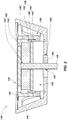
- FIG. 1 is a simplified cross-sectional view illustrating an audio driver assembly 110, in accordance with an embodiment of the disclosure.
- the audio driver assembly 110 includes a driver housing 116, an audio driver 118 secured within the driver housing 116, and a stabilizer 120 extending through the driver housing 116 and into the audio driver 118. While FIG. 1 depicts a particular configuration of the audio driver assembly 110, one of ordinary skill in the art will appreciate that different audio driver assembly configurations are known in the art which may be adapted to be employed in embodiments of the disclosure. FIG. 1 illustrates just one non-limiting example of the audio driver assembly 110.
- the driver housing 116 may be configured to be secured within an outer ear-cup housing of an ear-cup assembly, and includes at least one structure configured to at least partially enclose and support the audio driver 118.
- the driver housing 116 may be positioned over one or more sides (e.g., at least a back side) of the audio driver 118.
- An acoustical cavity 122 may be disposed between the driver housing 116 and the one or more sides of the audio driver 118.
- the driver housing 116 may also exhibit one or more apertures 124 (e.g., ports, holes, etc.) extending therethrough.
- the location and configuration (e.g., size, shape, etc.) of the apertures 124 may be selected to provide a desired emitted sound pressure level (SPL) profile, and/or a desired detectable SPL profile, for the audio driver assembly 110 and a headphone including the audio driver assembly 110.
- the apertures 124 in the driver housing 116 may, for example, include at least one bottom aperture 128 extending through a bottom portion of the driver housing 116, and at least one side aperture 126 extending through a side portion of the driver housing 116. As shown in FIG. 1 , the bottom aperture 128 may be centrally positioned within the bottom portion of the driver housing 116, and the side aperture 126 may be positioned within the side portion of the driver housing 116.
- At least one of the apertures 124 in the driver housing 116 may be at least partially (e.g., substantially) aligned with at least one aperture in the audio driver 118.
- the bottom aperture 128 of the driver housing 116 may be substantially aligned with a centrally located aperture 132 of the audio driver 118.
- the stabilizer 120 may be positioned within the bottom aperture 128 of the driver housing 116 and the centrally located aperture 132 of the audio driver 118 of the audio driver 118, as described in further detail below.
- the driver housing 116 may be formed of and include at least one of a metal material (e.g., a metal, a metal alloy, etc.) and a polymer material (e.g., a plastic).
- the audio driver 118 includes a magnet/coil assembly 136 and a flexible diaphragm 138 overlying the magnet/coil assembly 136.
- One or more components (e.g., the magnet/coil assembly 136, the flexible diaphragm 138, etc.) of the audio driver 118 may be coupled (e.g., directly coupled, indirectly coupled, or a combination thereof) to one or more portions of the driver housing 116 using, for example, an adhesive, a snap-fit, a welding process, or any other suitable method.
- the magnet/coil assembly 136 may include a permanent magnet 140, a voice coil 142 circumscribing the permanent magnet 140, and a yoke cup 144 at least partially surrounding the permanent magnet 140 and the voice coil 142.
- the permanent magnet 140 may be located on (e.g., directly physically contact, abut, etc.) a lower portion 146 of the yoke cup 144, and an upper portion 148 of the yoke cup 144 may be located on an upper surface of the permanent magnet 140.
- the upper portion 148 of the yoke cup 144 may at least partially extend over and surround (e.g., cover, envelop, etc.) peripheral sidewalls (e.g., outer sidewalls) of each of the permanent magnet 140 and the lower portion 146 of the yoke cup 144. At least a portion of the voice coil 142 may be located within a cavity at least partially defined by inner sidewalls of the upper portion 148 of the yoke cup 144 and the peripheral sidewalls of each of the permanent magnet 140 and the lower portion 146 of the yoke cup 144.
- the voice coil 142 may be offset (e.g., spaced apart, separated, etc.) from each of the permanent magnet 140 and the yoke cup 144, and may be electrically coupled to conductive terminals of the audio driver 118.
- the voice coil 142 and the yoke cup 144 may each independently be formed of and include an electrically conductive material, such as a metal material (e.g., a metal, a metal alloy, etc.).
- a metal material e.g., a metal, a metal alloy, etc.
- one or more apertures 130 may at least partially extend through the magnet/coil assembly 136.
- the apertures 130 in the magnet/coil assembly 136 may, for example, include the centrally located aperture 132, and one or more non-centrally located apertures 134. As shown in FIG. 1 , the centrally located aperture 132 may extend through the lower portion 146 of the yoke cup 144 and the permanent magnet 140 to the upper portion 148 of the yoke cup 144, and the non-centrally located apertures 134 may extend through at least the upper portion 148 of the yoke cup 144. A width of the centrally located aperture 132 may be substantially the same as or may be different than (e.g., less than, greater than) a width of the bottom aperture 128 of the driver housing 116 thereunder.
- the stabilizer 120 may be partially disposed within the centrally located aperture 132 (as well as the bottom aperture 128 of the driver housing 116), and may physically contact a lower surface of the upper portion 148 of the yoke cup 144, as described in further detail below.
- the flexible diaphragm 138 may be positioned on or over the upper portion 148 of the yoke cup 144 of the magnet/coil assembly 136. At least a peripheral portion (e.g., an outer rim) of the flexible diaphragm 138 may be attached (e.g., coupled, bonded, adhered, connected, etc.) to the driver housing 116. A central portion of the flexible diaphragm 138 may be attached to the upper portion 148 of the yoke cup 144.
- the flexible diaphragm 138 may be configured to vibrate in accordance with movement of one or more components (e.g., the permanent magnet 140 and the yoke cup 144) of the magnet/coil assembly 136 responsive to a magnetic field produced by the voice coil 142 of the magnet/coil assembly 136 upon receiving an audio signal.
- the flexible diaphragm 138 is formed of and includes a polymer material (e.g., a plastic).
- the stabilizer 120 is positioned and configured to limit lateral movement (e.g., side-to-side movement, rocking movement, etc.) of one or more components of the magnet/coil assembly 136, while also permitting longitudinal movement (e.g., upward movement and downward movement) of the one or more components of the magnet/coil assembly 136.
- lateral movement e.g., side-to-side movement, rocking movement, etc.
- longitudinal movement e.g., upward movement and downward movement
- each of the terms “longitudinal” and “vertical” means and includes extending in a direction substantially perpendicular to at least the flexible diaphragm 138, regardless of the orientation of the flexible diaphragm 138.
- the stabilizer 120 may be positioned and configured to substantially limit lateral movement of at least the permanent magnet 140 and the yoke cup 144, while permitting longitudinal movement of at least the permanent magnet 140 and the yoke cup 144. Limiting the lateral movement of the one or more components of the magnet/coil assembly 136 using the stabilizer 120 may prevent damage to the magnet/coil assembly 136 (and, hence, the audio driver 118) that may otherwise occur if the stabilizer 120 was not present in the audio driver assembly 110.
- the stabilizer 120 may prevent damage to (e.g., breakage of) the voice coil 146 that may otherwise occur if lateral movement of the permanent magnet 140 and the yoke cup 144 were unimpeded. Such unimpeded lateral movement may, for example, occur if a headphone including a conventional audio driver assembly were dropped and/or suddenly moved (e.g., jerked).
- the position and configuration (e.g., shape, size, and material composition) of the stabilizer 120 may be selected relative to positions and configurations of other components of the audio driver assembly 110 to provide the audio driver assembly 110 with desired acoustic properties, as described in further detail below.
- the stabilizer 120 longitudinally extends through driver housing 116, the acoustical cavity 122, and at least a portion of the magnet/coil assembly 136.
- the stabilizer 120 may also be substantially centrally located relative to widths (e.g., diameters) of the driver housing 116, the magnet/coil assembly 136, and the flexible diaphragm 138.
- widths e.g., diameters
- the stabilizer 120 may longitudinally extend from a location outside of the driver housing 116 through each of the bottom aperture 128 of the driver housing 116, the acoustical cavity 122, and the centrally located aperture 132 of the magnet/coil assembly 136, and may terminate (e.g., stop, end, etc.) at the upper portion 148 of the yoke cup 144.
- the stabilizer 120 may longitudinally extend to and terminate at a different location within the magnet/coil assembly 136 (e.g., at an upper surface of the upper portion 148 of the yoke cup 144, at a location within the upper portion 148 of the yoke cup 144, at a location within the permanent magnet 140, at an upper surface of the lower portion 146 of the yoke cup 144, at a location within the lower portion 146 of the yoke cup 144, etc.).
- the stabilizer 120 may exhibit a lateral cross-sectional shape that compliments the lateral cross-sectional shape of each of the centrally located aperture 132 of the magnet/coil assembly 136 and the bottom aperture 128 of the driver housing 116.
- the stabilizer 120, the centrally located aperture 132 of the magnet/coil assembly 136 and the bottom aperture 128 of the driver housing 116 may each exhibit a substantially circular lateral cross-section shape.
- the stabilizer 120 may exhibit one or more lateral cross-sectional dimensions (e.g., diameters, widths, etc.) permitting the stabilizer 120 to substantially laterally extend between one or more surfaces defining the centrally located aperture 132 of the magnet/coil assembly 136, and to at least partially (e.g., substantially) laterally extend between one or more surfaces defining the bottom aperture 128 of the driver housing 116.
- the stabilizer 120 may exhibit a longitudinal cross-sectional dimension (e.g., height) permitting the stabilizer 120 to longitudinally extend beyond the lower surface of the driver housing 116.
- the stabilizer 120 may be formed of and include at least one of a polymer material (e.g., a plastic) and metal material (e.g., a metal, a metal alloy, etc.).
- the material composition of the stabilizer 120 may be selected to provide the stabilizer 120 with properties (e.g., flexure, stiffness, etc.) sufficient to substantially impede or prevent lateral movement of one or more components of the magnet/coil assembly 136 (e.g., the permanent magnet 140 and the yoke cup 144), and may also be selected to provide the audio driver assembly 110 with desired acoustic properties.
- a stabilizer 120 formed of and including a metal material may impede lateral movement of components of the magnet/coil assembly 136 and may also provide the audio driver 118 with relatively lower resonance than a stabilizer 120 formed of and including a polymer material (e.g., at least partially due to the relatively increased density of a metal material as compared to a polymer material).
- the stabilizer 120 is formed of and includes a metal material.
- the stabilizer 120 may be attached (e.g., adhered, bonded, coupled, etc.) to one of more surfaces (e.g., surfaces of at least one of the permanent magnet 140, the lower portion 146 of the yoke cup 144, and the upper portion 148 of the yoke cup 144) defining the centrally located aperture 132 of the magnet/coil assembly 136, and may be unattached (e.g., unadhered, unbonded, uncoupled, etc.) to surfaces defining the bottom aperture 128 of the driver housing 116.
- surfaces e.g., surfaces of at least one of the permanent magnet 140, the lower portion 146 of the yoke cup 144, and the upper portion 148 of the yoke cup 14
- unattached e.g., unadhered, unbonded, uncoupled, etc.
- the stabilizer 120 may move longitudinally (e.g., move upward, move downward) in accordance with the longitudinal movement of one or more components (e.g., the permanent magnet 140 and the yoke cup 144) of the magnet/coil assembly 136.
- the stabilizer 120 may be attached to one of more surfaces defining the bottom aperture 128 of the driver housing 116, and may be unattached surfaces defining the centrally located aperture 132 of the magnet/coil assembly 136. Accordingly, in such additional embodiments, the stabilizer 120 may remain substantially stationary during longitudinal movement of one or more components (e.g., the permanent magnet 140 and the yoke cup 144) of the magnet/coil assembly 136.
- a vibration dampener may be included in the audio driver assembly 110 at the location where the stabilizer 120 extends through the driver housing 116.
- the vibration dampener may intervene between the stabilizer 120 and the driver housing 116, and may be configured to reduce the vibration amplitude at resonance of one or more components of audio driver assembly 110 (e.g., the stabilizer 120; components the audio driver 118, such as the permanent magnet 140, the yoke cup 144, and the flexible diaphragm 138; etc.).
- the vibration dampener may facilitate a relatively more even (e.g. uniform) vibration response for the audio driver assembly 110 across a relatively wider range of frequencies.
- FIG. 2 illustrates a simplified cross-sectional view of an audio driver assembly 110' including a vibration dampener 150, in accordance with another embodiment of the disclosure.
- the audio driver assembly 110' may be substantially similar to the audio driver assembly 110 previously described in relation to FIG. 1 , except that the audio driver assembly 110' includes the vibration dampener 150 between the stabilizer 120 and the driver housing 116.
- the vibration dampener 150 may be configured to at least partially circumscribe and physically contact (e.g., abut) the stabilizer 120.
- the vibration dampener 150 may comprise an annular structure surrounding and physically contacting sidewalls of the stabilizer 120. As shown in FIG.
- the vibration dampener 150 may be disposed adjacent the driver housing 116 in a centrally located bottom aperture 128' extending through the driver housing 116.
- the centrally located bottom aperture 128' may be larger than the second, centrally located bottom aperture 128 previously described in relation to the audio driver assembly 110 in order to accommodate (e.g., at least partially contain) the vibration dampener 150.
- the vibration dampener 150 may exhibit a smaller, centrally located aperture 152 extending therethrough, wherein the centrally located aperture 152 is sized and shaped to receive and physically contact the stabilizer 120.
- the stabilizer 120 may be unattached to (e.g., unadhered to, unbonded to, etc.) surfaces of the vibration dampener 150 defining the centrally located aperture 152 (and attached to surfaces of the magnet/coil assembly 136 defining the centrally located aperture 132). At least friction resulting from the physical contact of the stabilizer 120 and the vibration dampener 150 may hinder longitudinal movement of the stabilizer 120 and reduce the vibration amplitude at resonance of the stabilizer 120 and one or more components of the audio driver 118 (e.g., the permanent magnet 140, the yoke cup 144, and the flexible diaphragm 138).
- the audio driver 118 e.g., the permanent magnet 140, the yoke cup 144, and the flexible diaphragm 138.
- the vibration dampener 150 may be formed of and include any material suitable for dampening vibration of the stabilizer 120 and the one or components of the audio driver 118.
- the vibration dampener 150 may be formed of and include at least one of silicon, rubber, and foam.
- the vibration dampener 150 comprises an annular foam structure.
- FIG. 3 illustrates a simplified cross-sectional view of an audio driver assembly 110" including a ferrofluidic vibration dampener 154, in accordance with another embodiment of the disclosure.
- the audio driver assembly 110" may be substantially similar to the audio driver assembly 110' previously described in relation to FIG. 2 , except that the audio driver assembly 110" includes the ferrofluidic vibration dampener 154. As shown in FIG.
- the ferrofluidic vibration dampener 154 at least partially circumscribes the stabilizer 120 and comprises a magnet assembly 156 adjacent the driver housing 116, and a ferrofluid 158 disposed between and physically contacting each of the magnet assembly 156 and the stabilizer 120.
- the magnet assembly 156 may be configured and operated to modify one or more properties of the ferrofluid 158 to control the amount (e.g., extent, degree, etc.) of dampening provided by the ferrofluidic vibration dampener 154.
- the magnet assembly 156 may modify a magnetic field generated by a magnet thereof based at least partially on a current signal supplied to the magnet assembly 156 so as to polarize or depolarize ferromagnetic particles (e.g., iron oxide (Fe 3 O 4 ) particles) the ferrofluid 158.
- ferromagnetic particles e.g., iron oxide (Fe 3 O 4 ) particles
- Polarizing the ferromagnetic particles may increase the viscosity of the ferrofluid 158 so as to increase the amount of dampening provided by the ferrofluidic vibration dampener 154.
- the viscosity of the ferrofluid 158 in physical contact with the stabilizer 120 may hinder longitudinal movement of the stabilizer 120 and reduce the vibration amplitude at resonance of the stabilizer 120 and one or more components of the audio driver 118 (e.g., the permanent magnet 140, the yoke cup 144, and the flexible diaphragm 138).
- depolarizing the ferromagnetic particles may decrease the viscosity of the ferrofluid 158 so as to decrease the amount of dampening provided by the ferrofluidic vibration dampener 154.
- the stabilizer 120 may be unattached to (e.g., unadhered to, unbonded to, etc.) surfaces of the ferrofluidic vibration dampener 154 (e.g., surfaces of defining the centrally located aperture 152), and attached to surfaces of the magnet/coil assembly 136 defining the centrally located aperture 132.
- FIG. 4 is a simplified cross-sectional view illustrating the audio driver assembly 110 of FIG. 1 within an ear-cup assembly 102.
- the ear-cup assembly 102 may include an outer ear-cup housing 106 including at least two members assembled together around the audio driver assembly 110.
- the outer ear-cup housing 106 may include a front member 112, and a back member 114 connected to the front member 112.
- the members of the outer ear-cup housing 106 may each independently be formed of and include at least one of a metal material (e.g., a metal, a metal alloy, etc.) and a polymer material (e.g., a plastic), and may serve as a frame structure for the ear-cup assembly 102.
- the ear-cup assembly 102 may also include a cushion 108 attached to or otherwise carried on the outer ear-cup housing 106.
- the ear-cup assembly 102 may, alternatively, include the audio driver assembly 110' of FIG. 2 or the audio driver assembly 110" of FIG. 3 secured therein.
- FIG. 5 is simplified longitudinal view of a headphone 100 including two of the ear-cup assemblies 102 of FIG. 4 , and a headband 104 connected to each of the ear-cup assemblies 102.
- the headband 104 may be configured to rest on the head of a user and to support the ear-cup assemblies 102 on or over the user's ears.
- the headphone 100 may be configured to receive an electronic audio signal from a media player 109 through a connection 107 (e.g., a wired connection, a wireless connection, etc.) between the headphone 100 and the media player 109.
- the media player 109 may comprise any device or system capable of producing an audio signal.
- the media player 109 may comprise a portable digital music player, a portable compact disc player, a portable cassette player, a mobile phone, a smartphone, a personal digital assistant (PDA), a radio (e.g ., AM radio, FM radio, HD radio, satellite radio, etc.), a television, an ebook reader, a portable gaming system, a portable DVD player, a laptop computer, a tablet computer, a desktop computer, a stereo system, and/or other devices or systems that may be created hereafter.
- PDA personal digital assistant
Landscapes
- Engineering & Computer Science (AREA)
- Physics & Mathematics (AREA)
- Acoustics & Sound (AREA)
- Signal Processing (AREA)
- Manufacturing & Machinery (AREA)
- Electromagnetism (AREA)
- Headphones And Earphones (AREA)
- Audible-Bandwidth Dynamoelectric Transducers Other Than Pickups (AREA)
Description
- The disclosure, in various embodiments, relates generally to audio driver assemblies, to headphones including audio driver assemblies, and to related methods of forming headphones. More specifically, embodiments of the disclosure relate to audio driver assemblies including a driver housing, an audio driver, and a stabilizer extending through the driver housing and into a magnet assembly, to headphones including such audio driver assemblies, and to methods of forming such headphones.
- Conventional headphones include two ear-cup housings each including an audio driver assembly having an audio driver that produces audible sound waves. The audio driver may, for example, include a magnet/coil assembly secured within a driver housing, and a flexible diaphragm adjacent the magnet/coil assembly and attached to the driver housing. The positive and negative electrical terminals for the audio driver are respectively soldered to ends of wires, which extend to an audio jack (e.g., a tip-sleeve (TS) connector, a tip-ring-sleeve (TRS) connector, a tip-ring-ring-sleeve (TRRS) connector, etc.). The audio jack may be coupled to a media player such as a mobile phone, a digital media player, a computer, a television, etc., and the audio signal is transmitted to the audio driver in the audio driver assembly within the headphone through the wires.
- The acoustic performance of a headphone is conventionally a function of both the audio driver, as well as the configuration of the audio driver assembly and the ear-cup housing within which the audio driver is disposed. The audio driver assembly and the ear-cup housing of conventional headphones typically define acoustical cavities that affect the acoustics of the headphone. Thus, the manufacturer of the headphones may design the ear-cup housing and audio driver assembly of a headphone for use with a selected audio driver, so as to provide the headphone with acoustics deemed desirable by the manufacturer.
-
US 2011/0243370 A1 discloses a loudspeaker including a frame, a coil tube, a diaphragm, a first magnetic element, a connecting seat, a second magnetic element, a first damping membrane and a second damping membrane. The first magnetic element has a first end connected to a central position of the diaphragm and is received in the coil tube. The first magnetic element is a permanent magnet. The connecting seat has a first end connected to a second end of the first magnetic element and is received in the coil tube. The connecting seat further has a second end protrudingly provided with a central post. The second magnetic element is centrally provided with an aperture and has a first end connected to the second end of the connecting seat. The central post passes through the aperture and juts out of the first end of the coil tube. The second magnetic element is also a permanent magnet. The second damping membrane has a central position connected and fixed to a bottom side of the central post. -
US 2002/0025052 A1 discloses an electroacoustic transducer comprising a base, a magnetic core, a coil, a magnet and a diaphragm, which are received in a housing. The diaphragm is made of magnetic material. A disc-like magnetic piece is fixed to the front centre of the diaphragm. The columnar magnetic core is provided erectly at the centre of the base, and a coil is disposed around the magnetic core. A coil bobbin for holding the coil is fitted to the magnetic core. - The invention provides an audio driver assembly as defined in claim 1, a headphone as defined in claim 14 and a method of forming a headphone as defined in claim 15.
- Embodiments according to the invention are in particular disclosed in the attached claims. In accordance with one embodiment described herein, an audio driver assembly comprises a driver housing and an audio driver secured within the driver housing. The audio driver comprises a magnet assembly, a flexible diaphragm overlying the magnet assembly, and a stabilizer extending through the driver housing and into the magnet assembly.
- In additional embodiments, a headphone comprises an ear-cup housing and an audio driver assembly disposed at least partially within the ear-cup housing. The audio driver assembly comprises a driver housing, a flexible diaphragm suspended from the driver housing, a magnet assembly underlying the diaphragm, and a stabilizer extending through the driver housing and into the magnet assembly. The magnet assembly comprises a permanent magnet, a voice coil circumscribing the permanent magnet, and a yoke cup at least partially surrounding the permanent magnet and the voice coil.
- In additional embodiments, a method of forming a headphone comprises forming an audio driver assembly, and attaching the audio driver assembly within an ear-cup housing. The audio driver assembly comprises a driver housing, a flexible diaphragm suspended from the driver housing, a magnet assembly underlying the diaphragm, and a stabilizer extending through the driver housing and into the magnet assembly. The magnet assembly comprises a permanent magnet, a voice coil circumscribing the permanent magnet, and a yoke cup at least partially surrounding the permanent magnet and the voice coil.
-
-
FIG. 1 is a simplified cross-sectional side view illustrating an audio driver assembly of the ear-cup assembly, in accordance with an embodiment of disclosure. -
FIG. 2 is a simplified cross-sectional side view illustrating another audio driver assembly, in accordance with another embodiment of disclosure. -
FIG. 3 is a simplified cross-sectional side view illustrating another audio driver assembly, in accordance with a further embodiment of disclosure. -
FIG. 4 is a cross-sectional view of an ear-cup assembly including the audio driver assembly ofFIG. 1 , in accordance with an embodiment of disclosure. -
FIG. 5 is a simplified elevation view of a headphone including the ear-cup assembly ofFIG. 4 , in accordance with an embodiment of disclosure. - Audio driver assemblies are disclosed, as are headphones including audio driver assemblies, and methods of forming headphones. The audio driver assembly includes a driver housing, an audio driver secured within driver housing, and a stabilizer extending through the driver housing and into the audio driver. The audio driver comprises a magnet
assembly and a flexible diaphragm overlying the magnet assembly. The stabilizer is configured and positioned to impede or prevent lateral movement of one or more components of the magnet assembly, reducing the risk of damage to the audio driver that may otherwise result from such lateral movement. In additional embodiments, the audio driver assembly may also include a vibration dampener disposed between the driver housing and the stabilizer. The vibration dampener may be configured and positioned to reduce the vibration amplitude at resonance of one or more components of audio driver assembly. - The following description provides specific details, such as material compositions and processing conditions, in order to provide a thorough description of embodiments of the present disclosure. However, a person of ordinary skill in the art would understand that the embodiments of the disclosure may be practiced without employing these specific details. Indeed, the embodiments of the disclosure may be practiced in conjunction with conventional audio driver assembly fabrication techniques employed in the industry. In addition, the description provided below does not form a complete process flow for manufacturing an audio driver assembly or audio device (e.g., headphone). Only those process acts and structures necessary to understand the embodiments of the disclosure are described in detail below. Additional acts to form a complete audio device from the structures and assemblies described herein may be performed by conventional fabrication processes.
- Drawings presented herein are for illustrative purposes only, and are not meant to be actual views of any particular material, component, structure, device, or system. Variations from the shapes depicted in the drawings as a result, for example, of manufacturing techniques and/or tolerances, are to be expected. Thus, embodiments described herein are not to be construed as being limited to the particular shapes or regions as illustrated, but include deviations in shapes that result, for example, from manufacturing. For example, a region illustrated or described as box-shaped may have rough and/or nonlinear features, and a region illustrated or described as round may include some rough and/or linear features. Moreover, sharp angles that are illustrated may be rounded, and vice versa. Thus, the regions illustrated in the figures are schematic in nature, and their shapes are not intended to illustrate the precise shape of a region and do not limit the scope of the present claims. The drawings are not necessarily to scale. Additionally, elements common between figures may retain the same numerical designation.
- As used herein, the terms "comprising," "including," "containing," "characterized by," and grammatical equivalents thereof are inclusive or open-ended terms that do not exclude additional, unrecited elements or method steps, but also include the more restrictive terms "consisting of" and "consisting essentially of" and grammatical equivalents thereof. As used herein, the term "may" with respect to a material, structure, feature or method act indicates that such is contemplated for use in implementation of an embodiment of the disclosure and such term is used in preference to the more restrictive term "is" so as to avoid any implication that other, compatible materials, structures, features and methods usable in combination therewith should or must be, excluded.
- As used herein, the singular forms "a," "an," and "the" are intended to include the plural forms as well, unless the context clearly indicates otherwise.
- As used herein, "and/or" includes any and all combinations of one or more of the associated listed items.
- As used herein, spatially relative terms, such as "beneath," "below," "lower," "bottom," "above," "upper," "top," "front," "rear," "left," "right," and the like, may be used for ease of description to describe one element's or feature's relationship to another element(s) or feature(s) as illustrated in the figures. Unless otherwise specified, the spatially relative terms are intended to encompass different orientations of the materials in addition to the orientation depicted in the figures. For example, if materials in the figures are inverted, elements described as "below" or "beneath" or "under" or "on bottom of" other elements or features would then be oriented "above" or "on top of" the other elements or features. Thus, the term "below" can encompass both an orientation of above and below, depending on the context in which the term is used, which will be evident to one of ordinary skill in the art. The materials may be otherwise oriented (e.g., rotated 90 degrees, inverted, flipped) and the spatially relative descriptors used herein interpreted accordingly.
- As used herein, the term "substantially" in reference to a given parameter, property, or condition means and includes to a degree that one of ordinary skill in the art would understand that the given parameter, property, or condition is met with a degree of variance, such as within acceptable manufacturing tolerances. By way of example, depending on the particular parameter, property, or condition that is substantially met, the parameter, property, or condition may be at least 90.0% met, at least 95.0% met, at least 99.0% met, or even at least 99.9% met.
- As used herein, the term "about" in reference to a given parameter is inclusive of the stated value and has the meaning dictated by the context (e.g., it includes the degree of error associated with measurement of the given parameter).
-
FIG. 1 is a simplified cross-sectional view illustrating anaudio driver assembly 110, in accordance with an embodiment of the disclosure. Theaudio driver assembly 110 includes adriver housing 116, anaudio driver 118 secured within thedriver housing 116, and astabilizer 120 extending through thedriver housing 116 and into theaudio driver 118. WhileFIG. 1 depicts a particular configuration of theaudio driver assembly 110, one of ordinary skill in the art will appreciate that different audio driver assembly configurations are known in the art which may be adapted to be employed in embodiments of the disclosure.FIG. 1 illustrates just one non-limiting example of theaudio driver assembly 110. - The
driver housing 116 may be configured to be secured within an outer ear-cup housing of an ear-cup assembly, and includes at least one structure configured to at least partially enclose and support theaudio driver 118. Thedriver housing 116 may be positioned over one or more sides (e.g., at least a back side) of theaudio driver 118. Anacoustical cavity 122 may be disposed between thedriver housing 116 and the one or more sides of theaudio driver 118. Thedriver housing 116 may also exhibit one or more apertures 124 (e.g., ports, holes, etc.) extending therethrough. The location and configuration (e.g., size, shape, etc.) of theapertures 124 may be selected to provide a desired emitted sound pressure level (SPL) profile, and/or a desired detectable SPL profile, for theaudio driver assembly 110 and a headphone including theaudio driver assembly 110. Theapertures 124 in thedriver housing 116 may, for example, include at least onebottom aperture 128 extending through a bottom portion of thedriver housing 116, and at least oneside aperture 126 extending through a side portion of thedriver housing 116. As shown inFIG. 1 , thebottom aperture 128 may be centrally positioned within the bottom portion of thedriver housing 116, and theside aperture 126 may be positioned within the side portion of thedriver housing 116. At least one of theapertures 124 in thedriver housing 116 may be at least partially (e.g., substantially) aligned with at least one aperture in theaudio driver 118. By way of non-limiting example, thebottom aperture 128 of thedriver housing 116 may be substantially aligned with a centrally locatedaperture 132 of theaudio driver 118. Thestabilizer 120 may be positioned within thebottom aperture 128 of thedriver housing 116 and the centrally locatedaperture 132 of theaudio driver 118 of theaudio driver 118, as described in further detail below. Thedriver housing 116 may be formed of and include at least one of a metal material (e.g., a metal, a metal alloy, etc.) and a polymer material (e.g., a plastic). - The
audio driver 118 includes a magnet/coil assembly 136 and aflexible diaphragm 138 overlying the magnet/coil assembly 136. One or more components (e.g., the magnet/coil assembly 136, theflexible diaphragm 138, etc.) of theaudio driver 118 may be coupled (e.g., directly coupled, indirectly coupled, or a combination thereof) to one or more portions of thedriver housing 116 using, for example, an adhesive, a snap-fit, a welding process, or any other suitable method. - The magnet/
coil assembly 136 may include apermanent magnet 140, avoice coil 142 circumscribing thepermanent magnet 140, and ayoke cup 144 at least partially surrounding thepermanent magnet 140 and thevoice coil 142. As shown inFIG. 1 , thepermanent magnet 140 may be located on (e.g., directly physically contact, abut, etc.) alower portion 146 of theyoke cup 144, and anupper portion 148 of theyoke cup 144 may be located on an upper surface of thepermanent magnet 140. Theupper portion 148 of theyoke cup 144 may at least partially extend over and surround (e.g., cover, envelop, etc.) peripheral sidewalls (e.g., outer sidewalls) of each of thepermanent magnet 140 and thelower portion 146 of theyoke cup 144. At least a portion of thevoice coil 142 may be located within a cavity at least partially defined by inner sidewalls of theupper portion 148 of theyoke cup 144 and the peripheral sidewalls of each of thepermanent magnet 140 and thelower portion 146 of theyoke cup 144. Thevoice coil 142 may be offset (e.g., spaced apart, separated, etc.) from each of thepermanent magnet 140 and theyoke cup 144, and may be electrically coupled to conductive terminals of theaudio driver 118. Thevoice coil 142 and theyoke cup 144 may each independently be formed of and include an electrically conductive material, such as a metal material (e.g., a metal, a metal alloy, etc.). In addition, as depicted inFIG. 1 , one or more apertures 130 (e.g., ports, holes, etc.) may at least partially extend through the magnet/coil assembly 136. Theapertures 130 in the magnet/coil assembly 136 may, for example, include the centrally locatedaperture 132, and one or more non-centrally locatedapertures 134. As shown inFIG. 1 , the centrally locatedaperture 132 may extend through thelower portion 146 of theyoke cup 144 and thepermanent magnet 140 to theupper portion 148 of theyoke cup 144, and the non-centrally locatedapertures 134 may extend through at least theupper portion 148 of theyoke cup 144. A width of the centrally locatedaperture 132 may be substantially the same as or may be different than (e.g., less than, greater than) a width of thebottom aperture 128 of thedriver housing 116 thereunder. Thestabilizer 120 may be partially disposed within the centrally located aperture 132 (as well as thebottom aperture 128 of the driver housing 116), and may physically contact a lower surface of theupper portion 148 of theyoke cup 144, as described in further detail below. - The
flexible diaphragm 138 may be positioned on or over theupper portion 148 of theyoke cup 144 of the magnet/coil assembly 136. At least a peripheral portion (e.g., an outer rim) of theflexible diaphragm 138 may be attached (e.g., coupled, bonded, adhered, connected, etc.) to thedriver housing 116. A central portion of theflexible diaphragm 138 may be attached to theupper portion 148 of theyoke cup 144. Theflexible diaphragm 138 may be configured to vibrate in accordance with movement of one or more components (e.g., thepermanent magnet 140 and the yoke cup 144) of the magnet/coil assembly 136 responsive to a magnetic field produced by thevoice coil 142 of the magnet/coil assembly 136 upon receiving an audio signal. In some embodiments, theflexible diaphragm 138 is formed of and includes a polymer material (e.g., a plastic). - The
stabilizer 120 is positioned and configured to limit lateral movement (e.g., side-to-side movement, rocking movement, etc.) of one or more components of the magnet/coil assembly 136, while also permitting longitudinal movement (e.g., upward movement and downward movement) of the one or more components of the magnet/coil assembly 136. As used herein, each of the terms "literal" and "horizontal" means and includes extending in a direction substantially parallel to at least theflexible diaphragm 138, regardless of the orientation of theflexible diaphragm 138. Accordingly, each of the terms "longitudinal" and "vertical" means and includes extending in a direction substantially perpendicular to at least theflexible diaphragm 138, regardless of the orientation of theflexible diaphragm 138. For example, thestabilizer 120 may be positioned and configured to substantially limit lateral movement of at least thepermanent magnet 140 and theyoke cup 144, while permitting longitudinal movement of at least thepermanent magnet 140 and theyoke cup 144. Limiting the lateral movement of the one or more components of the magnet/coil assembly 136 using thestabilizer 120 may prevent damage to the magnet/coil assembly 136 (and, hence, the audio driver 118) that may otherwise occur if thestabilizer 120 was not present in theaudio driver assembly 110. By way of non-limiting example, thestabilizer 120 may prevent damage to (e.g., breakage of) thevoice coil 146 that may otherwise occur if lateral movement of thepermanent magnet 140 and theyoke cup 144 were unimpeded. Such unimpeded lateral movement may, for example, occur if a headphone including a conventional audio driver assembly were dropped and/or suddenly moved (e.g., jerked). The position and configuration (e.g., shape, size, and material composition) of thestabilizer 120 may be selected relative to positions and configurations of other components of theaudio driver assembly 110 to provide theaudio driver assembly 110 with desired acoustic properties, as described in further detail below. - The
stabilizer 120 longitudinally extends throughdriver housing 116, theacoustical cavity 122, and at least a portion of the magnet/coil assembly 136. Thestabilizer 120 may also be substantially centrally located relative to widths (e.g., diameters) of thedriver housing 116, the magnet/coil assembly 136, and theflexible diaphragm 138. By way of non-limiting example, as shown inFIG. 1 , thestabilizer 120 may longitudinally extend from a location outside of thedriver housing 116 through each of thebottom aperture 128 of thedriver housing 116, theacoustical cavity 122, and the centrally locatedaperture 132 of the magnet/coil assembly 136, and may terminate (e.g., stop, end, etc.) at theupper portion 148 of theyoke cup 144. In additional embodiments, thestabilizer 120 may longitudinally extend to and terminate at a different location within the magnet/coil assembly 136 (e.g., at an upper surface of theupper portion 148 of theyoke cup 144, at a location within theupper portion 148 of theyoke cup 144, at a location within thepermanent magnet 140, at an upper surface of thelower portion 146 of theyoke cup 144, at a location within thelower portion 146 of theyoke cup 144, etc.). - The
stabilizer 120 may exhibit a lateral cross-sectional shape that compliments the lateral cross-sectional shape of each of the centrally locatedaperture 132 of the magnet/coil assembly 136 and thebottom aperture 128 of thedriver housing 116. By way of non-limiting example, thestabilizer 120, the centrally locatedaperture 132 of the magnet/coil assembly 136 and thebottom aperture 128 of thedriver housing 116 may each exhibit a substantially circular lateral cross-section shape. In addition, thestabilizer 120 may exhibit one or more lateral cross-sectional dimensions (e.g., diameters, widths, etc.) permitting thestabilizer 120 to substantially laterally extend between one or more surfaces defining the centrally locatedaperture 132 of the magnet/coil assembly 136, and to at least partially (e.g., substantially) laterally extend between one or more surfaces defining thebottom aperture 128 of thedriver housing 116. In addition, thestabilizer 120 may exhibit a longitudinal cross-sectional dimension (e.g., height) permitting thestabilizer 120 to longitudinally extend beyond the lower surface of thedriver housing 116. - The
stabilizer 120 may be formed of and include at least one of a polymer material (e.g., a plastic) and metal material (e.g., a metal, a metal alloy, etc.). The material composition of thestabilizer 120 may be selected to provide thestabilizer 120 with properties (e.g., flexure, stiffness, etc.) sufficient to substantially impede or prevent lateral movement of one or more components of the magnet/coil assembly 136 (e.g., thepermanent magnet 140 and the yoke cup 144), and may also be selected to provide theaudio driver assembly 110 with desired acoustic properties. As a non-limiting example, astabilizer 120 formed of and including a metal material may impede lateral movement of components of the magnet/coil assembly 136 and may also provide theaudio driver 118 with relatively lower resonance than astabilizer 120 formed of and including a polymer material (e.g., at least partially due to the relatively increased density of a metal material as compared to a polymer material). In some embodiments, thestabilizer 120 is formed of and includes a metal material. - The
stabilizer 120 may be attached (e.g., adhered, bonded, coupled, etc.) to one of more surfaces (e.g., surfaces of at least one of thepermanent magnet 140, thelower portion 146 of theyoke cup 144, and theupper portion 148 of the yoke cup 144) defining the centrally locatedaperture 132 of the magnet/coil assembly 136, and may be unattached (e.g., unadhered, unbonded, uncoupled, etc.) to surfaces defining thebottom aperture 128 of thedriver housing 116. Accordingly, thestabilizer 120 may move longitudinally (e.g., move upward, move downward) in accordance with the longitudinal movement of one or more components (e.g., thepermanent magnet 140 and the yoke cup 144) of the magnet/coil assembly 136. In additional embodiments, thestabilizer 120 may be attached to one of more surfaces defining thebottom aperture 128 of thedriver housing 116, and may be unattached surfaces defining the centrally locatedaperture 132 of the magnet/coil assembly 136. Accordingly, in such additional embodiments, thestabilizer 120 may remain substantially stationary during longitudinal movement of one or more components (e.g., thepermanent magnet 140 and the yoke cup 144) of the magnet/coil assembly 136. - Optionally, a vibration dampener may be included in the
audio driver assembly 110 at the location where thestabilizer 120 extends through thedriver housing 116. The vibration dampener may intervene between thestabilizer 120 and thedriver housing 116, and may be configured to reduce the vibration amplitude at resonance of one or more components of audio driver assembly 110 (e.g., thestabilizer 120; components theaudio driver 118, such as thepermanent magnet 140, theyoke cup 144, and theflexible diaphragm 138; etc.). The vibration dampener may facilitate a relatively more even (e.g. uniform) vibration response for theaudio driver assembly 110 across a relatively wider range of frequencies. - As a non-limiting example,
FIG. 2 illustrates a simplified cross-sectional view of anaudio driver assembly 110' including avibration dampener 150, in accordance with another embodiment of the disclosure. Theaudio driver assembly 110' may be substantially similar to theaudio driver assembly 110 previously described in relation toFIG. 1 , except that theaudio driver assembly 110' includes thevibration dampener 150 between thestabilizer 120 and thedriver housing 116. Thevibration dampener 150 may be configured to at least partially circumscribe and physically contact (e.g., abut) thestabilizer 120. For example, thevibration dampener 150 may comprise an annular structure surrounding and physically contacting sidewalls of thestabilizer 120. As shown inFIG. 2 , thevibration dampener 150 may be disposed adjacent thedriver housing 116 in a centrally located bottom aperture 128' extending through thedriver housing 116. The centrally located bottom aperture 128' may be larger than the second, centrally locatedbottom aperture 128 previously described in relation to theaudio driver assembly 110 in order to accommodate (e.g., at least partially contain) thevibration dampener 150. Thevibration dampener 150 may exhibit a smaller, centrally locatedaperture 152 extending therethrough, wherein the centrally locatedaperture 152 is sized and shaped to receive and physically contact thestabilizer 120. Thestabilizer 120 may be unattached to (e.g., unadhered to, unbonded to, etc.) surfaces of thevibration dampener 150 defining the centrally located aperture 152 (and attached to surfaces of the magnet/coil assembly 136 defining the centrally located aperture 132). At least friction resulting from the physical contact of thestabilizer 120 and thevibration dampener 150 may hinder longitudinal movement of thestabilizer 120 and reduce the vibration amplitude at resonance of thestabilizer 120 and one or more components of the audio driver 118 (e.g., thepermanent magnet 140, theyoke cup 144, and the flexible diaphragm 138). Thevibration dampener 150 may be formed of and include any material suitable for dampening vibration of thestabilizer 120 and the one or components of theaudio driver 118. For example, thevibration dampener 150 may be formed of and include at least one of silicon, rubber, and foam. In some embodiments, thevibration dampener 150 comprises an annular foam structure. - In additional embodiments, the
vibration dampener 150 may exhibit a different configuration than that depicted inFIG. 2 . By way of non-limiting example,FIG. 3 illustrates a simplified cross-sectional view of anaudio driver assembly 110" including aferrofluidic vibration dampener 154, in accordance with another embodiment of the disclosure. Theaudio driver assembly 110" may be substantially similar to theaudio driver assembly 110' previously described in relation toFIG. 2 , except that theaudio driver assembly 110" includes theferrofluidic vibration dampener 154. As shown inFIG. 3 , theferrofluidic vibration dampener 154 at least partially circumscribes thestabilizer 120 and comprises amagnet assembly 156 adjacent thedriver housing 116, and aferrofluid 158 disposed between and physically contacting each of themagnet assembly 156 and thestabilizer 120. Themagnet assembly 156 may be configured and operated to modify one or more properties of theferrofluid 158 to control the amount (e.g., extent, degree, etc.) of dampening provided by theferrofluidic vibration dampener 154. For example, themagnet assembly 156 may modify a magnetic field generated by a magnet thereof based at least partially on a current signal supplied to themagnet assembly 156 so as to polarize or depolarize ferromagnetic particles (e.g., iron oxide (Fe3O4) particles) theferrofluid 158. Polarizing the ferromagnetic particles may increase the viscosity of theferrofluid 158 so as to increase the amount of dampening provided by theferrofluidic vibration dampener 154. Namely, increasing the viscosity of theferrofluid 158 in physical contact with thestabilizer 120 may hinder longitudinal movement of thestabilizer 120 and reduce the vibration amplitude at resonance of thestabilizer 120 and one or more components of the audio driver 118 (e.g., thepermanent magnet 140, theyoke cup 144, and the flexible diaphragm 138). Conversely, depolarizing the ferromagnetic particles may decrease the viscosity of theferrofluid 158 so as to decrease the amount of dampening provided by theferrofluidic vibration dampener 154. Thestabilizer 120 may be unattached to (e.g., unadhered to, unbonded to, etc.) surfaces of the ferrofluidic vibration dampener 154 (e.g., surfaces of defining the centrally located aperture 152), and attached to surfaces of the magnet/coil assembly 136 defining the centrally locatedaperture 132. - Referring collectively to
FIGS. 1 through 3 , in operation, current is caused to flow through thevoice coil 142, the magnitude of which fluctuates according to the electrical signal carried by the current. The interaction between the magnetic field of thepermanent magnet 140 and the fluctuating magnetic field generated by the current flowing through thevoice coil 142 results in a upward and downward movement (i.e., vibration) of at least thediaphragm 138,permanent magnet 140 and the yoke cup 144 (and, optionally, the stabilizer 120) relative to thevoice coil 142 and thedriver housing 116. The vibrations of theflexible diaphragm 138 result in the emission of audible sound from theflexible diaphragm 138. -
FIG. 4 is a simplified cross-sectional view illustrating theaudio driver assembly 110 ofFIG. 1 within an ear-cup assembly 102. The ear-cup assembly 102 may include an outer ear-cup housing 106 including at least two members assembled together around theaudio driver assembly 110. As a non-limiting example, the outer ear-cup housing 106 may include afront member 112, and aback member 114 connected to thefront member 112. The members of the outer ear-cup housing 106 (e.g., thefront member 112, theback member 114, etc.) may each independently be formed of and include at least one of a metal material (e.g., a metal, a metal alloy, etc.) and a polymer material (e.g., a plastic), and may serve as a frame structure for the ear-cup assembly 102. The ear-cup assembly 102 may also include acushion 108 attached to or otherwise carried on the outer ear-cup housing 106. The ear-cup assembly 102 may, alternatively, include theaudio driver assembly 110' ofFIG. 2 or theaudio driver assembly 110" ofFIG. 3 secured therein. -
FIG. 5 is simplified longitudinal view of aheadphone 100 including two of the ear-cup assemblies 102 ofFIG. 4 , and aheadband 104 connected to each of the ear-cup assemblies 102. Theheadband 104 may be configured to rest on the head of a user and to support the ear-cup assemblies 102 on or over the user's ears. Theheadphone 100 may be configured to receive an electronic audio signal from amedia player 109 through a connection 107 (e.g., a wired connection, a wireless connection, etc.) between theheadphone 100 and themedia player 109. Themedia player 109 may comprise any device or system capable of producing an audio signal. By way of non-limiting example, themedia player 109 may comprise a portable digital music player, a portable compact disc player, a portable cassette player, a mobile phone, a smartphone, a personal digital assistant (PDA), a radio (e.g., AM radio, FM radio, HD radio, satellite radio, etc.), a television, an ebook reader, a portable gaming system, a portable DVD player, a laptop computer, a tablet computer, a desktop computer, a stereo system, and/or other devices or systems that may be created hereafter.
Claims (15)
- An audio driver assembly, comprising:a driver housing (116); andan audio driver (118) secured within the driver housing (116) and comprising:a magnet assembly (136),wherein the magnet assembly (136) comprisesa permanent magnet (140) anda voice coil (142) circumscribing the permanent magnet (140);a flexible diaphragm (138) overlying the magnet assembly (136); anda stabilizer (120) extending through the driver housing (116) and into the magnet assembly (136), characterised in that the magnet assembly further comprises a yoke cup (144) at least partially surrounding the permanent magnet (140) and the voice coil (142).
- The audio driver assembly of claim 1, wherein the yoke cup (144) comprises:a lower portion (146) underlying a lower surface of the permanent magnet (140); andan upper portion (148) overlying an upper surface of the permanent magnet (140) and at least partially extending over and surrounding peripheral sidewalls of each of the permanent magnet (140) and the lower portion (146) of the yoke cup (144).
- The audio driver assembly of claim 1 or claim 2, wherein at least portion of the voice coil (142) is located within a cavity (122) at least partially defined by inner sidewalls of the upper portion (148) of the yoke cup (144) and the peripheral sidewalls of each of the permanent magnet (140) and the lower portion (146) of the yoke cup (144).
- The audio driver assembly of any of claims 1 to 3, wherein the stabilizer (120) longitudinally extends from a location outside of the driver housing (116) to a lower surface of the upper portion (148) of the yoke cup (144).
- The audio driver assembly of any one of claims 1 through 4, wherein the stabilizer (120) is located adjacent central portions of each of the driver housing (116) and the magnet assembly (136).
- The audio driver assembly of any one of claims 1 through 5, wherein the stabilizer (120) is disposed within substantially aligned, centrally located apertures (128;128',132) in the driver housing (116) and the magnet assembly (136).
- The audio driver assembly of any one of claims 1 through 6, wherein the stabilizer (120) is attached to at least one surface of the magnet assembly (136).
- The audio driver assembly of any one of claims 1 through 7, wherein the stabilizer (120) is attached to at least one surface of the driver housing (116).
- The audio driver assembly of any one of claims 1 through 8, wherein the stabilizer (120) comprises at least one of a metal material and a polymer material.
- The audio driver assembly of any one of claims 1 through 9, further comprising a vibration dampener (150;154) disposed laterally between driver housing (116) and the stabilizer (120).
- The audio driver assembly of claim 10, wherein at least a portion of the vibration dampener (154) is located within an aperture (128') extending through the driver housing (116), and at least a portion of the stabilizer (154) is located within another aperture (152) extending through the vibration dampener (154).
- The audio driver assembly of claim 10 or 11, wherein the vibration dampener (150) comprises at least one of silicon, rubber and foam.
- The audio driver assembly of claim 10 or claim 11, wherein the vibration dampener (154) comprises a ferrofluidic vibration dampener comprising:another magnet assembly (156) adjacent the driver housing (116); anda ferrofluid (158) between the other magnet assembly (156) and the stabilizer (120).
- A headphone, comprising:an ear-cup housing (106); andan audio driver assembly (110;110') as recited in any one of claims 1 through 13 disposed at least partially within the ear-cup housing (106).
- A method of forming a headphone (100), comprising:providing an audio driver assembly (110;110') as recited in any one of claims 1 through 13; andattaching the audio driver assembly (110;110') within an ear-cup housing (106).
Applications Claiming Priority (1)
| Application Number | Priority Date | Filing Date | Title |
|---|---|---|---|
| US201462099010P | 2014-12-31 | 2014-12-31 |
Publications (2)
| Publication Number | Publication Date |
|---|---|
| EP3041260A1 EP3041260A1 (en) | 2016-07-06 |
| EP3041260B1 true EP3041260B1 (en) | 2017-12-13 |
Family
ID=55070746
Family Applications (1)
| Application Number | Title | Priority Date | Filing Date |
|---|---|---|---|
| EP15202031.9A Active EP3041260B1 (en) | 2014-12-31 | 2015-12-22 | Audio driver assemblies, headphones including the audio driver assemblies, and related methods |
Country Status (3)
| Country | Link |
|---|---|
| US (1) | US9800978B2 (en) |
| EP (1) | EP3041260B1 (en) |
| CN (1) | CN105744413B (en) |
Families Citing this family (5)
| Publication number | Priority date | Publication date | Assignee | Title |
|---|---|---|---|---|
| US10462560B2 (en) * | 2018-01-08 | 2019-10-29 | Skullcandy, Inc. | Driver assemblies, headphones including driver assemblies, and related methods |
| US11032638B2 (en) * | 2019-07-16 | 2021-06-08 | Ngai Fun Cheung | Speaker with an integrated air pressure and vibration mitigation system |
| JP7532991B2 (en) * | 2020-07-31 | 2024-08-14 | ヤマハ株式会社 | Headphones |
| GB202204878D0 (en) * | 2022-04-04 | 2022-05-18 | Pss Belgium Nv | Loudspeaker |
| TWI838026B (en) * | 2022-12-21 | 2024-04-01 | 宏碁股份有限公司 | Speaker module |
Family Cites Families (14)
| Publication number | Priority date | Publication date | Assignee | Title |
|---|---|---|---|---|
| NL7001438A (en) | 1969-02-17 | 1970-08-19 | ||
| US6023515A (en) | 1997-02-21 | 2000-02-08 | Motorola, Inc. | Mass excited acoustic device |
| JP3747361B2 (en) | 2000-08-30 | 2006-02-22 | スター精密株式会社 | Electroacoustic transducer |
| US20040008858A1 (en) | 2002-05-02 | 2004-01-15 | Steere John F. | Acoustically enhanced electro-dynamic loudspeakers |
| US7634099B2 (en) | 2005-07-22 | 2009-12-15 | Logitech International, S.A. | High-fidelity earpiece with adjustable frequency response |
| CN2822084Y (en) * | 2005-09-06 | 2006-09-27 | 张凡 | Inner magnet type energy changer driver with resistance negative load property |
| US7876911B2 (en) | 2006-03-27 | 2011-01-25 | Freescale Semiconductor, Inc. | Headphone driver and methods for use therewith |
| US20080170710A1 (en) | 2006-11-13 | 2008-07-17 | Solteras, Inc. | Headphone driver with improved frequency response |
| JP5096193B2 (en) | 2008-03-07 | 2012-12-12 | 株式会社オーディオテクニカ | Headphone unit |
| JP5441164B2 (en) | 2010-02-03 | 2014-03-12 | 株式会社オーディオテクニカ | headphone |
| TW201136332A (en) | 2010-04-06 | 2011-10-16 | Zhao-Lang Wang | Loudspeaker with magnetic element fixed on the drum membrane |
| US20120114160A1 (en) | 2010-11-09 | 2012-05-10 | Cheng Uei Precision Industry Co., Ltd. | Tunable earphone |
| CN202095083U (en) * | 2011-06-17 | 2011-12-28 | 黄彩林 | Clamp type resonance audio acoustical generator |
| US9414145B2 (en) | 2013-03-15 | 2016-08-09 | Skullcandy, Inc. | Customizable headphone audio driver assembly, headphone including such an audio driver assembly, and related methods |
-
2015
- 2015-12-18 US US14/974,815 patent/US9800978B2/en active Active
- 2015-12-22 EP EP15202031.9A patent/EP3041260B1/en active Active
- 2015-12-30 CN CN201511016859.2A patent/CN105744413B/en active Active
Non-Patent Citations (1)
| Title |
|---|
| None * |
Also Published As
| Publication number | Publication date |
|---|---|
| US20160192076A1 (en) | 2016-06-30 |
| EP3041260A1 (en) | 2016-07-06 |
| CN105744413A (en) | 2016-07-06 |
| US9800978B2 (en) | 2017-10-24 |
| CN105744413B (en) | 2019-01-22 |
Similar Documents
| Publication | Publication Date | Title |
|---|---|---|
| EP2701400B1 (en) | Speakers, headphones, and kits related to vibrations in an audio system, and methods for forming same | |
| EP3054702B1 (en) | Speakers and headphones related to vibrations in an audio system, and methods for operating same | |
| US10397719B2 (en) | Ported headphones and related methods | |
| US9883290B2 (en) | Audio driver assembly, headphone including such an audio driver assembly, and related methods | |
| US9185494B2 (en) | Inner magnet type microspeaker | |
| CN104053085B (en) | Customizable headphone audio driver assembly, headphones, and related methods | |
| US9800978B2 (en) | Audio driver assemblies, headphones including the audio driver assemblies, and related methods | |
| EP3509322B1 (en) | Driver assemblies, headphones including driver assemblies, and related methods | |
| KR101156053B1 (en) | Micro-speaker | |
| US9386375B2 (en) | Miniature speaker | |
| KR20100138153A (en) | Multifunction micro speaker | |
| KR101096788B1 (en) | Multifunction micro speaker | |
| JP6188417B2 (en) | Hybrid speaker | |
| US20160227323A1 (en) | Receiver Having Diaphragm with Improved Rigidity | |
| CN204442664U (en) | Microspeaker | |
| CN102273226A (en) | Multifunctional microspeaker | |
| JP2008005002A (en) | Speaker damper and speaker using the same | |
| JP2011101074A (en) | Electrodynamic speaker and vibration member used therefor | |
| JP6253101B2 (en) | Electrodynamic electroacoustic transducer, diaphragm thereof, and method for producing electrodynamic electroacoustic transducer | |
| JP2018152730A (en) | Electroacoustic diaphragm and electroacoustic transducer using the same | |
| JP2008211675A (en) | Magnetic circuit and electrodynamic speaker using the same | |
| KR101152893B1 (en) | Speaker with inner damper | |
| KR20110105252A (en) | Vibration Speaker | |
| JPWO2017183370A1 (en) | Speaker unit and sound device |
Legal Events
| Date | Code | Title | Description |
|---|---|---|---|
| PUAI | Public reference made under article 153(3) epc to a published international application that has entered the european phase |
Free format text: ORIGINAL CODE: 0009012 |
|
| AK | Designated contracting states |
Kind code of ref document: A1 Designated state(s): AL AT BE BG CH CY CZ DE DK EE ES FI FR GB GR HR HU IE IS IT LI LT LU LV MC MK MT NL NO PL PT RO RS SE SI SK SM TR |
|
| AX | Request for extension of the european patent |
Extension state: BA ME |
|
| 17P | Request for examination filed |
Effective date: 20170103 |
|
| RBV | Designated contracting states (corrected) |
Designated state(s): AL AT BE BG CH CY CZ DE DK EE ES FI FR GB GR HR HU IE IS IT LI LT LU LV MC MK MT NL NO PL PT RO RS SE SI SK SM TR |
|
| GRAP | Despatch of communication of intention to grant a patent |
Free format text: ORIGINAL CODE: EPIDOSNIGR1 |
|
| INTG | Intention to grant announced |
Effective date: 20170725 |
|
| GRAS | Grant fee paid |
Free format text: ORIGINAL CODE: EPIDOSNIGR3 |
|
| GRAA | (expected) grant |
Free format text: ORIGINAL CODE: 0009210 |
|
| REG | Reference to a national code |
Ref country code: GB Ref legal event code: FG4D |
|
| REG | Reference to a national code |
Ref country code: AT Ref legal event code: REF Ref document number: 955391 Country of ref document: AT Kind code of ref document: T Effective date: 20171215 Ref country code: CH Ref legal event code: EP |
|
| REG | Reference to a national code |
Ref country code: IE Ref legal event code: FG4D |
|
| REG | Reference to a national code |
Ref country code: DE Ref legal event code: R096 Ref document number: 602015006642 Country of ref document: DE |
|
| REG | Reference to a national code |
Ref country code: NL Ref legal event code: MP Effective date: 20171213 |
|
| PG25 | Lapsed in a contracting state [announced via postgrant information from national office to epo] |
Ref country code: SE Free format text: LAPSE BECAUSE OF FAILURE TO SUBMIT A TRANSLATION OF THE DESCRIPTION OR TO PAY THE FEE WITHIN THE PRESCRIBED TIME-LIMIT Effective date: 20171213 Ref country code: FI Free format text: LAPSE BECAUSE OF FAILURE TO SUBMIT A TRANSLATION OF THE DESCRIPTION OR TO PAY THE FEE WITHIN THE PRESCRIBED TIME-LIMIT Effective date: 20171213 Ref country code: NO Free format text: LAPSE BECAUSE OF FAILURE TO SUBMIT A TRANSLATION OF THE DESCRIPTION OR TO PAY THE FEE WITHIN THE PRESCRIBED TIME-LIMIT Effective date: 20180313 |
|
| REG | Reference to a national code |
Ref country code: AT Ref legal event code: MK05 Ref document number: 955391 Country of ref document: AT Kind code of ref document: T Effective date: 20171213 |
|
| PG25 | Lapsed in a contracting state [announced via postgrant information from national office to epo] |
Ref country code: RS Free format text: LAPSE BECAUSE OF FAILURE TO SUBMIT A TRANSLATION OF THE DESCRIPTION OR TO PAY THE FEE WITHIN THE PRESCRIBED TIME-LIMIT Effective date: 20171213 Ref country code: GR Free format text: LAPSE BECAUSE OF FAILURE TO SUBMIT A TRANSLATION OF THE DESCRIPTION OR TO PAY THE FEE WITHIN THE PRESCRIBED TIME-LIMIT Effective date: 20180314 Ref country code: HR Free format text: LAPSE BECAUSE OF FAILURE TO SUBMIT A TRANSLATION OF THE DESCRIPTION OR TO PAY THE FEE WITHIN THE PRESCRIBED TIME-LIMIT Effective date: 20171213 Ref country code: BG Free format text: LAPSE BECAUSE OF FAILURE TO SUBMIT A TRANSLATION OF THE DESCRIPTION OR TO PAY THE FEE WITHIN THE PRESCRIBED TIME-LIMIT Effective date: 20180313 Ref country code: LV Free format text: LAPSE BECAUSE OF FAILURE TO SUBMIT A TRANSLATION OF THE DESCRIPTION OR TO PAY THE FEE WITHIN THE PRESCRIBED TIME-LIMIT Effective date: 20171213 |
|
| PG25 | Lapsed in a contracting state [announced via postgrant information from national office to epo] |
Ref country code: NL Free format text: LAPSE BECAUSE OF FAILURE TO SUBMIT A TRANSLATION OF THE DESCRIPTION OR TO PAY THE FEE WITHIN THE PRESCRIBED TIME-LIMIT Effective date: 20171213 |
|
| PG25 | Lapsed in a contracting state [announced via postgrant information from national office to epo] |
Ref country code: CZ Free format text: LAPSE BECAUSE OF FAILURE TO SUBMIT A TRANSLATION OF THE DESCRIPTION OR TO PAY THE FEE WITHIN THE PRESCRIBED TIME-LIMIT Effective date: 20171213 Ref country code: SK Free format text: LAPSE BECAUSE OF FAILURE TO SUBMIT A TRANSLATION OF THE DESCRIPTION OR TO PAY THE FEE WITHIN THE PRESCRIBED TIME-LIMIT Effective date: 20171213 Ref country code: ES Free format text: LAPSE BECAUSE OF FAILURE TO SUBMIT A TRANSLATION OF THE DESCRIPTION OR TO PAY THE FEE WITHIN THE PRESCRIBED TIME-LIMIT Effective date: 20171213 Ref country code: EE Free format text: LAPSE BECAUSE OF FAILURE TO SUBMIT A TRANSLATION OF THE DESCRIPTION OR TO PAY THE FEE WITHIN THE PRESCRIBED TIME-LIMIT Effective date: 20171213 Ref country code: CY Free format text: LAPSE BECAUSE OF FAILURE TO SUBMIT A TRANSLATION OF THE DESCRIPTION OR TO PAY THE FEE WITHIN THE PRESCRIBED TIME-LIMIT Effective date: 20171213 |
|
| PG25 | Lapsed in a contracting state [announced via postgrant information from national office to epo] |
Ref country code: IT Free format text: LAPSE BECAUSE OF FAILURE TO SUBMIT A TRANSLATION OF THE DESCRIPTION OR TO PAY THE FEE WITHIN THE PRESCRIBED TIME-LIMIT Effective date: 20171213 Ref country code: RO Free format text: LAPSE BECAUSE OF FAILURE TO SUBMIT A TRANSLATION OF THE DESCRIPTION OR TO PAY THE FEE WITHIN THE PRESCRIBED TIME-LIMIT Effective date: 20171213 Ref country code: IS Free format text: LAPSE BECAUSE OF FAILURE TO SUBMIT A TRANSLATION OF THE DESCRIPTION OR TO PAY THE FEE WITHIN THE PRESCRIBED TIME-LIMIT Effective date: 20180413 Ref country code: PL Free format text: LAPSE BECAUSE OF FAILURE TO SUBMIT A TRANSLATION OF THE DESCRIPTION OR TO PAY THE FEE WITHIN THE PRESCRIBED TIME-LIMIT Effective date: 20171213 Ref country code: AT Free format text: LAPSE BECAUSE OF FAILURE TO SUBMIT A TRANSLATION OF THE DESCRIPTION OR TO PAY THE FEE WITHIN THE PRESCRIBED TIME-LIMIT Effective date: 20171213 Ref country code: SM Free format text: LAPSE BECAUSE OF FAILURE TO SUBMIT A TRANSLATION OF THE DESCRIPTION OR TO PAY THE FEE WITHIN THE PRESCRIBED TIME-LIMIT Effective date: 20171213 |
|
| REG | Reference to a national code |
Ref country code: DE Ref legal event code: R097 Ref document number: 602015006642 Country of ref document: DE |
|
| REG | Reference to a national code |
Ref country code: IE Ref legal event code: MM4A |
|
| PG25 | Lapsed in a contracting state [announced via postgrant information from national office to epo] |
Ref country code: MT Free format text: LAPSE BECAUSE OF NON-PAYMENT OF DUE FEES Effective date: 20171222 Ref country code: LU Free format text: LAPSE BECAUSE OF NON-PAYMENT OF DUE FEES Effective date: 20171222 Ref country code: MC Free format text: LAPSE BECAUSE OF FAILURE TO SUBMIT A TRANSLATION OF THE DESCRIPTION OR TO PAY THE FEE WITHIN THE PRESCRIBED TIME-LIMIT Effective date: 20171213 |
|
| REG | Reference to a national code |
Ref country code: BE Ref legal event code: MM Effective date: 20171231 |
|
| PLBE | No opposition filed within time limit |
Free format text: ORIGINAL CODE: 0009261 |
|
| STAA | Information on the status of an ep patent application or granted ep patent |
Free format text: STATUS: NO OPPOSITION FILED WITHIN TIME LIMIT |
|
| PG25 | Lapsed in a contracting state [announced via postgrant information from national office to epo] |
Ref country code: IE Free format text: LAPSE BECAUSE OF NON-PAYMENT OF DUE FEES Effective date: 20171222 |
|
| 26N | No opposition filed |
Effective date: 20180914 |
|
| PG25 | Lapsed in a contracting state [announced via postgrant information from national office to epo] |
Ref country code: BE Free format text: LAPSE BECAUSE OF NON-PAYMENT OF DUE FEES Effective date: 20171231 Ref country code: DK Free format text: LAPSE BECAUSE OF FAILURE TO SUBMIT A TRANSLATION OF THE DESCRIPTION OR TO PAY THE FEE WITHIN THE PRESCRIBED TIME-LIMIT Effective date: 20171213 |
|
| REG | Reference to a national code |
Ref country code: FR Ref legal event code: ST Effective date: 20181030 |
|
| PG25 | Lapsed in a contracting state [announced via postgrant information from national office to epo] |
Ref country code: FR Free format text: LAPSE BECAUSE OF NON-PAYMENT OF DUE FEES Effective date: 20180213 Ref country code: SI Free format text: LAPSE BECAUSE OF FAILURE TO SUBMIT A TRANSLATION OF THE DESCRIPTION OR TO PAY THE FEE WITHIN THE PRESCRIBED TIME-LIMIT Effective date: 20171213 |
|
| PG25 | Lapsed in a contracting state [announced via postgrant information from national office to epo] |
Ref country code: HU Free format text: LAPSE BECAUSE OF FAILURE TO SUBMIT A TRANSLATION OF THE DESCRIPTION OR TO PAY THE FEE WITHIN THE PRESCRIBED TIME-LIMIT; INVALID AB INITIO Effective date: 20151222 |
|
| REG | Reference to a national code |
Ref country code: CH Ref legal event code: PL |
|
| PG25 | Lapsed in a contracting state [announced via postgrant information from national office to epo] |
Ref country code: MK Free format text: LAPSE BECAUSE OF FAILURE TO SUBMIT A TRANSLATION OF THE DESCRIPTION OR TO PAY THE FEE WITHIN THE PRESCRIBED TIME-LIMIT Effective date: 20171213 |
|
| PG25 | Lapsed in a contracting state [announced via postgrant information from national office to epo] |
Ref country code: CH Free format text: LAPSE BECAUSE OF NON-PAYMENT OF DUE FEES Effective date: 20181231 Ref country code: LI Free format text: LAPSE BECAUSE OF NON-PAYMENT OF DUE FEES Effective date: 20181231 |
|
| PG25 | Lapsed in a contracting state [announced via postgrant information from national office to epo] |
Ref country code: TR Free format text: LAPSE BECAUSE OF FAILURE TO SUBMIT A TRANSLATION OF THE DESCRIPTION OR TO PAY THE FEE WITHIN THE PRESCRIBED TIME-LIMIT Effective date: 20171213 |
|
| PG25 | Lapsed in a contracting state [announced via postgrant information from national office to epo] |
Ref country code: PT Free format text: LAPSE BECAUSE OF FAILURE TO SUBMIT A TRANSLATION OF THE DESCRIPTION OR TO PAY THE FEE WITHIN THE PRESCRIBED TIME-LIMIT Effective date: 20171213 |
|
| PG25 | Lapsed in a contracting state [announced via postgrant information from national office to epo] |
Ref country code: LT Free format text: LAPSE BECAUSE OF FAILURE TO SUBMIT A TRANSLATION OF THE DESCRIPTION OR TO PAY THE FEE WITHIN THE PRESCRIBED TIME-LIMIT Effective date: 20171213 |
|
| PG25 | Lapsed in a contracting state [announced via postgrant information from national office to epo] |
Ref country code: AL Free format text: LAPSE BECAUSE OF FAILURE TO SUBMIT A TRANSLATION OF THE DESCRIPTION OR TO PAY THE FEE WITHIN THE PRESCRIBED TIME-LIMIT Effective date: 20171213 |
|
| PGFP | Annual fee paid to national office [announced via postgrant information from national office to epo] |
Ref country code: GB Payment date: 20251229 Year of fee payment: 11 |
|
| PGFP | Annual fee paid to national office [announced via postgrant information from national office to epo] |
Ref country code: DE Payment date: 20251229 Year of fee payment: 11 |