EP3041088A1 - Antenna device - Google Patents
Antenna device Download PDFInfo
- Publication number
- EP3041088A1 EP3041088A1 EP13892395.8A EP13892395A EP3041088A1 EP 3041088 A1 EP3041088 A1 EP 3041088A1 EP 13892395 A EP13892395 A EP 13892395A EP 3041088 A1 EP3041088 A1 EP 3041088A1
- Authority
- EP
- European Patent Office
- Prior art keywords
- antenna device
- ground electrode
- feed plate
- electrode
- dielectric layer
- Prior art date
- Legal status (The legal status is an assumption and is not a legal conclusion. Google has not performed a legal analysis and makes no representation as to the accuracy of the status listed.)
- Granted
Links
Images





Classifications
-
- H—ELECTRICITY
- H01—ELECTRIC ELEMENTS
- H01Q—ANTENNAS, i.e. RADIO AERIALS
- H01Q1/00—Details of, or arrangements associated with, antennas
- H01Q1/36—Structural form of radiating elements, e.g. cone, spiral, umbrella; Particular materials used therewith
- H01Q1/38—Structural form of radiating elements, e.g. cone, spiral, umbrella; Particular materials used therewith formed by a conductive layer on an insulating support
-
- H—ELECTRICITY
- H01—ELECTRIC ELEMENTS
- H01Q—ANTENNAS, i.e. RADIO AERIALS
- H01Q1/00—Details of, or arrangements associated with, antennas
- H01Q1/12—Supports; Mounting means
- H01Q1/22—Supports; Mounting means by structural association with other equipment or articles
- H01Q1/24—Supports; Mounting means by structural association with other equipment or articles with receiving set
- H01Q1/241—Supports; Mounting means by structural association with other equipment or articles with receiving set used in mobile communications, e.g. GSM
- H01Q1/242—Supports; Mounting means by structural association with other equipment or articles with receiving set used in mobile communications, e.g. GSM specially adapted for hand-held use
- H01Q1/245—Supports; Mounting means by structural association with other equipment or articles with receiving set used in mobile communications, e.g. GSM specially adapted for hand-held use with means for shaping the antenna pattern, e.g. in order to protect user against rf exposure
-
- H—ELECTRICITY
- H01—ELECTRIC ELEMENTS
- H01Q—ANTENNAS, i.e. RADIO AERIALS
- H01Q13/00—Waveguide horns or mouths; Slot antennas; Leaky-waveguide antennas; Equivalent structures causing radiation along the transmission path of a guided wave
- H01Q13/10—Resonant slot antennas
- H01Q13/106—Microstrip slot antennas
-
- H—ELECTRICITY
- H01—ELECTRIC ELEMENTS
- H01Q—ANTENNAS, i.e. RADIO AERIALS
- H01Q9/00—Electrically-short antennas having dimensions not more than twice the operating wavelength and consisting of conductive active radiating elements
- H01Q9/04—Resonant antennas
- H01Q9/0407—Substantially flat resonant element parallel to ground plane, e.g. patch antenna
-
- H—ELECTRICITY
- H01—ELECTRIC ELEMENTS
- H01Q—ANTENNAS, i.e. RADIO AERIALS
- H01Q9/00—Electrically-short antennas having dimensions not more than twice the operating wavelength and consisting of conductive active radiating elements
- H01Q9/04—Resonant antennas
- H01Q9/0407—Substantially flat resonant element parallel to ground plane, e.g. patch antenna
- H01Q9/0421—Substantially flat resonant element parallel to ground plane, e.g. patch antenna with a shorting wall or a shorting pin at one end of the element
-
- H—ELECTRICITY
- H01—ELECTRIC ELEMENTS
- H01Q—ANTENNAS, i.e. RADIO AERIALS
- H01Q9/00—Electrically-short antennas having dimensions not more than twice the operating wavelength and consisting of conductive active radiating elements
- H01Q9/04—Resonant antennas
- H01Q9/0407—Substantially flat resonant element parallel to ground plane, e.g. patch antenna
- H01Q9/045—Substantially flat resonant element parallel to ground plane, e.g. patch antenna with particular feeding means
-
- H—ELECTRICITY
- H01—ELECTRIC ELEMENTS
- H01Q—ANTENNAS, i.e. RADIO AERIALS
- H01Q9/00—Electrically-short antennas having dimensions not more than twice the operating wavelength and consisting of conductive active radiating elements
- H01Q9/04—Resonant antennas
- H01Q9/30—Resonant antennas with feed to end of elongated active element, e.g. unipole
- H01Q9/42—Resonant antennas with feed to end of elongated active element, e.g. unipole with folded element, the folded parts being spaced apart a small fraction of the operating wavelength
Definitions
- the present invention relates, for example, to an antenna device.
- a planar inverted F antenna has been proposed as an antenna advantageous for use with a portable wireless apparatus such as a mobile telephone.
- a slot acting as an antenna is formed between two portions of a ground electrode.
- an antenna element is connected via one terminal to one of the two portions of the ground electrode and is fed via that terminal, and the antenna element is grounded via another terminal to the other of the two portions of the ground electrode.
- the housing of the wireless apparatus equipped with the antenna is made as thin as possible.
- the thinner the housing the more difficult it becomes to increase the distance between the antenna and the human body.
- an object of the present invention is to provide an antenna device that can reduce SAR.
- an antenna device includes: a ground electrode; a first dielectric layer which is provided on one surface of the ground electrode; a feed plate which is provided on a surface of the first dielectric layer opposite from the ground electrode and is made of a conductor, and which is shorted to the ground electrode; a feed line which feeds to the feed plate; a second dielectric layer which is provided in such a manner as to sandwich the feed plate with the first dielectric layer; and a radiation electrode which is provided on a surface of the second dielectric layer opposite from the feed plate, and which is fed by being electrically connected to the feed plate at a feed point to radiate or receive a radiowave with a first frequency.
- the antenna device disclosed in this patent specification can reduce SAR.
- the antenna device includes a feed plate between a ground electrode and a radiation electrode, and the radiation electrode is fed via the feed plate. Since a portion of the radiowave radiated from the radiation electrode is blocked by the feed plate or the ground electrode, this arrangement serves to reduce SAR in the human body located on the ground electrode side. Furthermore, in the antenna device, a slit acting as an antenna is formed in the ground electrode, and a portion of the ground electrode is bent in a direction away from the radiation electrode so that the ground electrode is grounded via the bent portion. By thus providing a certain distance between the ground electrode and the human body and thereby reducing the absorption by the human body of the radiowave radiated from the ground electrode, the antenna device reduces SAR.
- Figure 1A is a perspective view of the antenna device according to one embodiment as viewed from the top thereof.
- Figure 1B is a perspective view of the antenna device of Figure 1A as viewed from the bottom thereof.
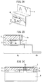
- Figure 2A is a perspective cutaway view depicting the electrodes of the antenna device of Figure 1A .
- Figure 2B is a side cutaway view depicting the electrodes of the antenna device of Figure 1A .
- Figure 2C is a front cutaway view depicting the electrodes of the antenna device of Figure 1A .
- a plane parallel to the surface of the radiation electrode 2 is hereinafter referred to as the horizontal plane.
- a direction perpendicular to the horizontal plane is referred to as the vertical direction of the antenna device 1, and the ground electrode is understood to be located at the lowermost end.
- the antenna device 1 includes, in order from top to bottom, the radiation electrode 2, the upper dielectric layer 3, the feed plate 4, the lower dielectric layer 5, and the ground electrode 6.
- the antenna device 1 further includes a feed line 7 which feeds to the feed plate 4 and which is connected to a communication circuit (not depicted) for communicating with other apparatus by means of radiowaves radiated or received by the antenna device 1.
- the antenna device 1 is mounted in a wireless apparatus, such as a tablet PC, with the ground electrode 6 facing the bottom surface of the housing of the wireless apparatus and with the radiation electrode 2 facing the top surface of the housing.
- the radiation electrode 2, the feed plate 4, and the ground electrode 6 are each formed from a metal such as aluminum, copper, gold, silver, or nickel, or an alloy based on some of these metals, or from some other suitable electrically conductive material.
- the upper dielectric layer 3 and the lower dielectric layer 5 are each formed, for example, from FR4 or from some other suitable dielectric material.
- the dielectric material forming the upper dielectric layer 3 and the dielectric material forming the lower dielectric layer 5 may be the same or may be different from each other.
- Figure 3 is a plan view of the antenna device 1, depicting the shape of the radiation electrode 2.
- the radiation electrode 2 is provided on the upper surface of the upper dielectric layer 3, and radiates or receives a radiowave having a first resonant frequency f 1 . Therefore, the radiation electrode 2 is formed so that the length measured from a feed point 2a connected to vias 3a formed in the upper dielectric layer 3 to an end 2b of the radiation electrode 2 becomes equal to one quarter of a wavelength ⁇ 1 corresponding to the first resonant frequency f 1 so as to be able to resonate with a radiowave having the first resonant frequency f 1 . Further, in the present embodiment, the radiation electrode 2 is constructed in a substantially U-shaped form in order to reduce the size of the antenna device 1 in the horizontal plane.
- the upper dielectric layer 3 is formed with its top surface contacting the radiation electrode 2 and with its bottom surface contacting the top surface of the feed plate 4.
- the radiation electrode 2 is supported on the upper dielectric layer 3.
- Two vias 3a are formed through the upper dielectric layer 3, and the radiation electrode 2 and the feed plate 4 are electrically connected by the vias 3a so that the radiation electrode 2 is fed from the feed plate 4 through the vias 3a.
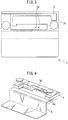
- Figure 4 is a perspective view depicting a surface of the lower dielectric layer 5.
- the lower dielectric layer 5 is formed with its top surface contacting the feed plate 4 and with its bottom surface contacting the top surface of the ground electrode 6.
- the upper dielectric layer 3 and the lower dielectric layer 5 support the feed plate 4 therebetween so that the feed plate 4 is substantially parallel with the radiation electrode 2.
- the upper dielectric layer 3 and the lower dielectric layer 5 are fixed together, for example, with resin screws.
- the upper dielectric layer 3 and the lower dielectric layer 5 may be fixed together by adhesive means.
- the lower dielectric layer 5 is formed so as not to cover the slit 6c formed in the ground electrode 6, but the lower dielectric layer 5 may be formed so as to cover the entire electrode portion 6a of the ground electrode 6 including the slit 6c.
- the feed plate 4 is an electrically conductive plate, and is disposed between the radiation electrode 2 and the ground electrode 6 so as to be substantially parallel with the radiation electrode 2 and the electrode portion 6a of the ground electrode 6 and so that the longitudinal direction of the feed plate 4 substantially coincides with the longitudinal direction of the radiation electrode 2.
- the feed plate 4 is shorted to the ground electrode 6 via a short pin 6b of the ground electrode 6.
- the feed plate 4 is fed via the feed line 7 at a feed point 4a which is located at a position different from the position where the short pin 6b contacts.
- the feed plate 4 is electrically connected to the radiation electrode 2 through the two vias 3a formed in the upper dielectric layer 3. In this way, the radiation electrode 2 is fed via the feed plate 4 and the feed line 7.
- the number of vias 3a is not limited to any specific number, but the number of vias 3a may be one or may be three.
- the point where the short pin 6b contacts the feed plate 4 is spaced away from the vias 3a by a prescribed distance along the crosswise direction of the feed plate 4.
- the vias 3a and the feed point 4a are spaced away from each other by a prescribed distance along the longitudinal direction of the feed plate 4.
- the distance between the vias 3 and the contact point and the distance between the feed point 4a and the vias 3a are each determined according to the resonant frequency f 1 of the radiation electrode 2.
- the lower the resonant frequency f 1 the longer the distance between the feed point 4a and the vias 3a.
- the distance between the vias 3a and the point where the short pin 6b contacts the feed plate 4 is set shorter as the resonant frequency f 1 becomes lower.
- FIG 5A is a plan view of the ground electrode 6, and Figure 5B is a perspective view of the ground electrode 6.
- the ground electrode 6 is formed, for example, from a metal plate to provide sufficient strength.
- the ground electrode 6 functions as a grounded conductor with respect to the radiation electrode 2, and also functions as an electrode for radiating or receiving a radiowave having a second resonant frequency f 2 .
- the ground electrode 6 has a grounding portion 6d in addition to the electrode portion 6a.
- the electrode portion 6a of the ground electrode 6 is disposed in contact with the bottom surface of the lower dielectric layer 5 and substantially parallel with the radiation electrode 2 and the feed plate 4.
- the short pin 6b protruding upward is formed on the electrode portion 6a in order to short the feed plate 4.
- the slit 6c is formed in the electrode portion 6a of the ground electrode 6.
- the slit 6c is disposed so that the longitudinal direction of the slit 6c substantially coincides with the longitudinal direction of the radiation electrode 2 in order to allow a portion of the radiowave radiated from the radiation electrode 2 to pass through.
- the slit 6c acts as an antenna for radiating or receiving a radiowave having the second resonant frequency f 2 .
- the slit 6c is formed so that the diagonal length of the slit 6c becomes equal to one quarter of a second wavelength ⁇ 2 corresponding to the second resonant frequency f 2 .
- the ground electrode 6 is connected to the feed line 7 at a position near the slit 6c and is fed via the feed line 7.
- the feed line 7 contacts the ground electrode 6 at a position where the impedance of the antenna formed by the slit 6c becomes equal to a predetermined value (for example, 50 ⁇ ).
- the grounding portion 6d of the ground electrode 6 is bent at a substantially right angle downward in a direction away from the radiation electrode 2. Then, at the bottom of the antenna device 1, the grounding portion 6d is bent at a substantially right angle so as to contact a conducting portion which is electrically connected to a metal plate acting as the ground electrode of the entire housing of the wireless apparatus equipped with the antenna device 1. In this way, the distance from the slit 6c to the bottom surface of the housing is increased. Since the increased distance serves to reduce the amount of the radiowave radiated from the slit 6c and the grounding portion 6d and absorbed by the human body located at a position contacting the bottom surface of the wireless apparatus, the antenna device 1 can reduce SAR.
- the ground electrode 6 is formed so that the width of the conductor forming the electrode portion 6a of the ground electrode 6 becomes larger than the width of the radiation electrode 2. Further, in the present embodiment, the feed plate 4 and the ground electrode 6 are arranged so that when the feed plate 4 and the ground electrode 6 are projected on the horizontal plane, at least a portion of the feed plate 4 overlaps the slit 6c. Then, the radiation electrode 2, the feed plate 4, and the ground electrode 6 are arranged so that when the radiation electrode 2, the feed plate 4, and the ground electrode 6 are projected on the horizontal plane, the radiation electrode 2 substantially overlaps the ground electrode 6 or the feed plate 4.
- the radiation electrode 2 and the feed plate 4 are arranged so that when the radiation electrode 2 and the feed plate 4 are projected on the horizontal plane, the feed point 2a of the radiation electrode 2 and its surrounding portion overlap the feed plate 4. As a result, the radiowave radiated from the feed point 2a and its surrounding portion where the current flowing through the radiation electrode 2 becomes strongest is blocked by the feed plate 4.
- the antenna device 1 can reduce SAR.
- the area of the feed plate 4 is smaller than the area of the radiation electrode 2.
- the radiation electrode 2, the feed plate 4, and the ground electrode 6 are arranged so that a portion of the radiation electrode 2 does not overlap the feed plate 4 but overlaps the slit 6c.
- a portion of the radiowave radiated from the radiation electrode 2 is allowed to be radiated outside the antenna device 1 without being blocked by the feed plate 4 or the ground electrode 6; this serves to substantially prevent degradation of the radiating characteristics of the antenna device 1 for a radiowave having a wavelength that resonates the radiation electrode 2.
- the feed plate 4 is smaller than the slit 6c, a portion of the radiowave radiated from the slit 6c is allowed to be radiated outside the antenna device 1 without being blocked by the feed plate 4. This serves to substantially prevent degradation, due to the presence of the feed plate 4, of the performance of the antenna device 1 for a radiowave having a wavelength corresponding to the resonant frequency f 2 of the slit 6c.
- the dimensions of the various portions of the antenna device 1 and the results of analysis of the SAR and radiation efficiency of the antenna device 1 will be described below for the case where the first resonant frequency f 1 of the radiation electrode 2 is 2.3 GHz and the second resonant frequency f 2 of the slit 6c is 5.5 GHz.
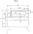
- Figure 6 is a plan view indicating the outer dimensions of the antenna device 1 and the dimensions of the radiation electrode 2.
- Figure 7 is a plan view indicating the dimensions of the ground electrode 6.
- the antenna device 1 has a length of 14.8 mm as measured along the longitudinal direction (hereinafter referred to as the x direction) of the radiation electrode 2, and a length of 11.21 mm as measured along the direction (hereinafter referred to as the y direction) orthogonal to the x direction in the horizontal plane.
- the substantially U-shaped radiation electrode 2 the length from the feed point 2a to the left edge is 6 mm, and the length of the radiation electrode 2 in the y direction is 4.14 mm.
- the length of the radiation electrode 2 in the x direction is 12.04 mm.
- the length, in the y direction, of the end portion of the radiation electrode 2 is 1.7 mm.
- the length, in the x direction, of the electrode portion 6a of the ground electrode 6 is 14.8 mm, and the length in the y direction is 6.54 mm.
- the length, in the x direction, of the portion of the electrode portion 6a located farther from the grounding portion 6d is 12.89 mm.
- the width of the narrowest portion of the slit 6c is 1.99 mm, and the diagonal length of the slit 6c is 11.4 mm.
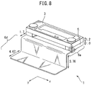
- Figure 8 is a perspective view of the antenna device 1, indicating the dimensions of the various portions in the vertical direction.
- the thickness of the upper dielectric layer 3 is 1.2 mm
- the thickness of the lower dielectric layer 5 is 1.0 mm.
- the relative permittivity of the upper dielectric layer 3 is 3.5
- the relative permittivity of the lower dielectric layer 5 is 2.9.
- the length from the edge portion of the lower dielectric layer 5 to the grounding portion 6d is 1.7 mm, and the length of the grounding portion 6d in the vertical direction is 3.76 mm.
- the length, in the y direction, of the bottom portion of the grounding portion 6d which is electrically connected to the conductor of the housing is 4.67 mm.
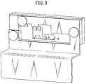
- Figure 9 is a perspective view of the antenna device 1, indicating the size of the feed plate 4.
- the length of the feed plate 4 in the x direction is 4.5 mm.
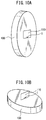
- Figure 10A is a diagram illustrating an arrangement of a phantom and a wireless apparatus, which corresponds to a situation where the wireless apparatus equipped with the antenna device 1 is placed on a lap.
- Figure 10B is a diagram illustrating an arrangement of a phantom and a wireless apparatus, which corresponds to a situation where the wireless apparatus equipped with the antenna device 1 is placed on a belly.
- the antenna device 1 is placed with its ground electrode disposed facing the bottom surface of the wireless apparatus 110 and in close proximity to one side of the wireless apparatus 110.
- the wireless apparatus 110 equipped with the antenna device 1 is placed so that the bottom surface of the wireless apparatus 110 contacts the surface of the phantom 100.
- this placement is hereinafter referred to as the horizontal placement.
- the wireless apparatus 110 equipped with the antenna device 1 is placed so that the bottom surface of the wireless apparatus 110 is perpendicular to the surface of the phantom 100 and so that the side on which the antenna device 1 is mounted contacts the phantom 100.
- this placement is hereinafter referred to as the vertical placement.
- the relative permittivity of the phantom used for analysis is 51.2 for 2.3 GHz and 48.7 for 5.5 GHz, the conductivity is 1.92 [S/m] for 2.3 GHz and 5.82 [S/m] for 5.5 GHz, and the density is 1000 [kg/m 3 ].
- the input power to the antenna device 1 is 16.0 [dBm] for 2.3 GHz and 17.0 [dBm] for 5.5 GHz.
- Figure 11 is a table indicating the results of the analysis of the SAR and radiation efficiency of the antenna device 1 performed using the Finite-Difference Time-Domain method.
- SAR is less than 1.6 [w/kg] for both of the first resonant frequency of 2.3 GHz and the second resonant frequency of 5.5 GHz, whether the placement be the horizontal placement or the vertical placement.
- the analysis of the radiation efficiency of the antenna device 1 also indicated good values, -3.6 [dB] for the first resonant frequency of 2.3 GHz and -4.0 [dB] for the second resonant frequency of 5.5 GHz. It is thus seen that the antenna device 1 achieves good performance in terms of both SAR and radiation efficiency.
- the feed plate is provided between the radiation electrode and the ground electrode, and the radiation electrode is fed via the feed plate, a portion of the radiowave radiated from the radiation electrode is blocked by the feed plate or the ground electrode, and as a result, SAR is reduced. Furthermore, in the antenna device, one end of the ground electrode is bent in a direction away from the radiation electrode, i.e., toward the bottom side, and is grounded to the conducting portion of the housing of the wireless apparatus.
- the antenna device since the spacing between the human body and the slit formed in the ground electrode and acting as an antenna can be made relatively large, the absorption by the human body of the radiowave radiated from the slit can be reduced, even when the human body is located on the bottom side of the housing. As a result, the antenna device can reduce SAR.
- the present invention is not limited to the above embodiment.
- FIG 12 is a schematic side view of a ground electrode according to a modified example, depicting the shape of the ground electrode.
- the ground electrode 6' according to the modified example of Figure 12 differs in that its electrode portion 6a' is extended in the y direction up to an end corresponding to the housing side end of the conducting portion 12 connected to the ground electrode (not depicted) of the entire housing. Then, the grounding portion 6d' is bent toward the housing side end of the conducting portion 12.
- the path of the current from the slit 6c formed in the ground electrode 6' to the conducting portion 12 becomes longer than the corresponding path in the above embodiment, and thus the current in the vicinity of the conducting portion 12 becomes smaller. Since this reduces the intensity of electromagnetic radiation in the vicinity of the human body located on the bottom side of the housing, SAR is further reduced.
- the antenna device may be configured to radiate or receive only radiowaves having a frequency with which the radiation electrode resonates.
- the distance from the ground electrode to the human body may be made shorter than in the case of the above embodiment, because there is no need to consider the radiowave radiated from the slit of the ground electrode.
- the ground electrode may be formed in a flat plate-like shape.
- the antenna device may include an additional dielectric layer located upwardly of the radiation electrode and an additional radiation electrode supported on the additional dielectric layer and capable of radiating or receiving a radiowave having a third resonant frequency.
- This additional radiation electrode is fed, for example, through a via formed in the additional dielectric layer in the same position as the via formed in the second dielectric layer.
- the antenna device can radiate or receive radiowaves of three different frequencies. It is preferable to arrange the additional radiation electrode so that when the additional radiation electrode, the feed plate, and the ground electrode are projected on the horizontal plane, the additional radiation electrode substantially overlaps the ground electrode or the feed plate. In this case, since a portion of the radiowave radiated from the additional radiation electrode is blocked by the feed plate or the ground electrode, SAR can also be reduced for the radiowave radiated from the additional radiation electrode.
- the radiation electrode may be formed in a straight line shape, or may be formed in an S shape or L shape.
- FIG. 13 is a diagram depicting one example of the placement of the antenna device in a wireless apparatus according to the above embodiment or modified example.
- the antenna device 1 is placed inside the rectangular-parallelepiped-shaped housing of the wireless apparatus, with the ground electrode 6 of the antenna device 1 facing the bottom surface 130 of the housing and with the radiation electrode 2 facing the top surface (not depicted) of the housing.
- a user interface such as a touch panel display (not depicted) is placed face up, i.e., to face the top surface of the housing. Therefore, generally the wireless apparatus is used with the bottom surface of the housing placed on a portion of the human body (for example, a lap).
- the bottom surface and top surface of the housing are formed from dielectric material such as a resin.
- the antenna device 1 is placed in such a manner that the bottom of the grounding portion of the ground electrode 6 contacts the conducting portion 1301 electrically connected to the ground electrode (not depicted) of the housing itself. It is preferable that the ground electrode of the housing itself is spaced away from the antenna device 1 so that the antenna device 1 can receive a radiowave from outside the housing and can transmit a radiowave outside the housing. It is also preferable that the antenna device 1 is placed, for example, in the vicinity of one of the sides of the housing in such a manner that the longitudinal direction of the slit and the radiation electrode is substantially parallel with the one side. In this case, when the wireless apparatus is placed in such a manner that the side of the housing in the vicinity of which the antenna device 1 is placed faces the human belly, SAR in the human belly is reduced.
- the orientation of the antenna device 1 may be determined according to the placement of the conducting portion so that the electrode portion of the ground electrode is located nearer to the side of the housing than the grounding portion is, or conversely, the orientation of the antenna device 1 may be determined so that the grounding portion of the ground electrode is located nearer to the side of the housing than the electrode portion is.
- the antenna device 1 may be placed in the vicinity of one of the corners of the housing. Since the current is relatively strong in the vicinity of the feed point of the radiation electrode, it is preferable that the feed point is located as far away from the human body as possible.
- the wireless apparatus is placed in such a manner that the side of the housing in the vicinity of which the antenna device 1 is placed faces the human belly, the position nearer to any one of the corners of the housing is farther from the human body, because the human body is substantially elliptical in cross section.
- the antenna device so that the feed point of the radiation electrode is located as close as possible to one of the corners of the housing; for example, when the feed point is located nearer to the left edge than the longitudinal center of the radiation electrode, it is preferable to place the antenna device in the left edge corner of the housing.
Landscapes
- Engineering & Computer Science (AREA)
- Computer Networks & Wireless Communication (AREA)
- Waveguide Aerials (AREA)
- Support Of Aerials (AREA)
Abstract
Description
- The present invention relates, for example, to an antenna device.
- A planar inverted F antenna has been proposed as an antenna advantageous for use with a portable wireless apparatus such as a mobile telephone. For example, in an antenna disclosed in
patent document 1, a slot acting as an antenna is formed between two portions of a ground electrode. Further, an antenna element is connected via one terminal to one of the two portions of the ground electrode and is fed via that terminal, and the antenna element is grounded via another terminal to the other of the two portions of the ground electrode. - [Patent document 1]
US Patent Application No. 2012/0092226 - In many countries around the world, regulations are implemented to limit human exposure to radiowaves in order to avoid harmful effects that radiowaves radiated from various apparatuses may have on the human body. For example, according to the guidelines set by the US Federal Communications Commission, it is provided that the specific absorption rate (SAR) be held to 1.6W/kg or below for wireless apparatuses such as tablet PCs. On the other hand, in Japan, a ministerial ordinance issued by the Ministry of Public Management, Home Affairs, Posts and Telecommunications requires that the local SAR not exceed 2W/kg for apparatuses such as mobile telephones.
- In order to reduce SAR, it is effective to increase the distance between the antenna and the human body. On the other hand, from the standpoint of enhancing portability, it is preferable that the housing of the wireless apparatus equipped with the antenna is made as thin as possible. However, the thinner the housing, the more difficult it becomes to increase the distance between the antenna and the human body.
- Accordingly, an object of the present invention is to provide an antenna device that can reduce SAR.
- According to one embodiment, an antenna device is provided. The antenna device includes: a ground electrode; a first dielectric layer which is provided on one surface of the ground electrode; a feed plate which is provided on a surface of the first dielectric layer opposite from the ground electrode and is made of a conductor, and which is shorted to the ground electrode; a feed line which feeds to the feed plate; a second dielectric layer which is provided in such a manner as to sandwich the feed plate with the first dielectric layer; and a radiation electrode which is provided on a surface of the second dielectric layer opposite from the feed plate, and which is fed by being electrically connected to the feed plate at a feed point to radiate or receive a radiowave with a first frequency.
- The object and advantages of the invention will be realized and attained by means of the elements and combinations particularly pointed out in the claims.
- It is to be understood that both the foregoing general description and the following detailed description are exemplary and explanatory and are not restrictive of the invention, as claimed.
- The antenna device disclosed in this patent specification can reduce SAR.
-
-
FIG. 1A is a perspective view of an antenna device according to one embodiment as viewed from the top thereof. -
FIG. 1B is a perspective view of the antenna device ofFIG. 1A as viewed from the bottom thereof. -
FIG. 2A is a perspective cutaway view depicting the electrodes of the antenna device ofFIG. 1A . -
FIG. 2B is a side cutaway view depicting the electrodes of the antenna device ofFIG. 1A . -
FIG. 2C is a front cutaway view depicting the electrodes of the antenna device ofFIG. 1A . -
FIG. 3 is a plan view of the antenna device, depicting the shape of a radiation electrode. -
FIG. 4 is a perspective view depicting a surface of a lower dielectric layer. -
FIG. 5A is a plan view of a ground electrode. -
FIG. 5B is a perspective view of the ground electrode. -
FIG. 6 is a plan view indicating the outer dimensions of the antenna device and the dimensions of the radiation electrode. -
FIG. 7 is a plan view indicating the dimensions of the ground electrode. -
FIG. 8 is a perspective view of the antenna device, indicating the dimensions of various portions in vertical direction. -
FIG. 9 is a perspective view of the antenna device, indicating the size of a feed plate. -
FIG. 10A is a diagram illustrating an arrangement of a phantom and a wireless apparatus, which corresponds to a situation where the wireless apparatus equipped with the antenna device is placed on a lap. -
FIG. 10B is a diagram illustrating an arrangement of a phantom and a wireless apparatus, which corresponds to a situation where the wireless apparatus equipped with the antenna device is placed on a belly. -
FIG. 11 is a table indicating the results of analysis of the SAR and radiation efficiency of the antenna device. -
FIG. 12 is a schematic side view of a ground electrode according to a modified example. -
FIG. 13 is a diagram depicting one example of the placement of the antenna device in a wireless apparatus according to the embodiment or modified example. - An antenna device will be described below with reference to the drawings.
- The antenna device includes a feed plate between a ground electrode and a radiation electrode, and the radiation electrode is fed via the feed plate. Since a portion of the radiowave radiated from the radiation electrode is blocked by the feed plate or the ground electrode, this arrangement serves to reduce SAR in the human body located on the ground electrode side. Furthermore, in the antenna device, a slit acting as an antenna is formed in the ground electrode, and a portion of the ground electrode is bent in a direction away from the radiation electrode so that the ground electrode is grounded via the bent portion. By thus providing a certain distance between the ground electrode and the human body and thereby reducing the absorption by the human body of the radiowave radiated from the ground electrode, the antenna device reduces SAR.
-
Figure 1A is a perspective view of the antenna device according to one embodiment as viewed from the top thereof.Figure 1B is a perspective view of the antenna device ofFigure 1A as viewed from the bottom thereof.Figure 2A is a perspective cutaway view depicting the electrodes of the antenna device ofFigure 1A .Figure 2B is a side cutaway view depicting the electrodes of the antenna device ofFigure 1A .Figure 2C is a front cutaway view depicting the electrodes of the antenna device ofFigure 1A . For convenience of explanation, a plane parallel to the surface of theradiation electrode 2 is hereinafter referred to as the horizontal plane. Further, a direction perpendicular to the horizontal plane is referred to as the vertical direction of theantenna device 1, and the ground electrode is understood to be located at the lowermost end. - As depicted in
Figures 1A, 1B , and2A to 2C , theantenna device 1 includes, in order from top to bottom, theradiation electrode 2, theupper dielectric layer 3, thefeed plate 4, the lowerdielectric layer 5, and theground electrode 6. Theantenna device 1 further includes afeed line 7 which feeds to thefeed plate 4 and which is connected to a communication circuit (not depicted) for communicating with other apparatus by means of radiowaves radiated or received by theantenna device 1. Theantenna device 1 is mounted in a wireless apparatus, such as a tablet PC, with theground electrode 6 facing the bottom surface of the housing of the wireless apparatus and with theradiation electrode 2 facing the top surface of the housing. - The
radiation electrode 2, thefeed plate 4, and theground electrode 6 are each formed from a metal such as aluminum, copper, gold, silver, or nickel, or an alloy based on some of these metals, or from some other suitable electrically conductive material. - The
upper dielectric layer 3 and the lowerdielectric layer 5 are each formed, for example, from FR4 or from some other suitable dielectric material. The dielectric material forming theupper dielectric layer 3 and the dielectric material forming the lowerdielectric layer 5 may be the same or may be different from each other. The higher the relative permittivity of the dielectric material forming theupper dielectric layer 3, the thinner theupper dielectric layer 3 can be made, i.e., the smaller the spacing between theradiation electrode 2 and thefeed plate 4 can be made. Likewise, the higher the relative permittivity of the dielectric material forming the lowerdielectric layer 5, the thinner the lowerdielectric layer 5 can be made, i.e., the smaller the spacing between thefeed plate 4 and theground electrode 6 can be made. -
Figure 3 is a plan view of theantenna device 1, depicting the shape of theradiation electrode 2. Theradiation electrode 2 is provided on the upper surface of theupper dielectric layer 3, and radiates or receives a radiowave having a first resonant frequency f1. Therefore, theradiation electrode 2 is formed so that the length measured from afeed point 2a connected tovias 3a formed in theupper dielectric layer 3 to anend 2b of theradiation electrode 2 becomes equal to one quarter of a wavelength λ1 corresponding to the first resonant frequency f1 so as to be able to resonate with a radiowave having the first resonant frequency f1. Further, in the present embodiment, theradiation electrode 2 is constructed in a substantially U-shaped form in order to reduce the size of theantenna device 1 in the horizontal plane. - The
upper dielectric layer 3 is formed with its top surface contacting theradiation electrode 2 and with its bottom surface contacting the top surface of thefeed plate 4. Theradiation electrode 2 is supported on theupper dielectric layer 3. Twovias 3a are formed through theupper dielectric layer 3, and theradiation electrode 2 and thefeed plate 4 are electrically connected by thevias 3a so that theradiation electrode 2 is fed from thefeed plate 4 through thevias 3a. -
Figure 4 is a perspective view depicting a surface of the lowerdielectric layer 5. The lowerdielectric layer 5 is formed with its top surface contacting thefeed plate 4 and with its bottom surface contacting the top surface of theground electrode 6. In other words, theupper dielectric layer 3 and the lowerdielectric layer 5 support thefeed plate 4 therebetween so that thefeed plate 4 is substantially parallel with theradiation electrode 2. Then, theupper dielectric layer 3 and the lowerdielectric layer 5 are fixed together, for example, with resin screws. Alternatively, theupper dielectric layer 3 and the lowerdielectric layer 5 may be fixed together by adhesive means. - In the present embodiment, the lower
dielectric layer 5 is formed so as not to cover theslit 6c formed in theground electrode 6, but the lowerdielectric layer 5 may be formed so as to cover theentire electrode portion 6a of theground electrode 6 including theslit 6c. - The
feed plate 4 is an electrically conductive plate, and is disposed between theradiation electrode 2 and theground electrode 6 so as to be substantially parallel with theradiation electrode 2 and theelectrode portion 6a of theground electrode 6 and so that the longitudinal direction of thefeed plate 4 substantially coincides with the longitudinal direction of theradiation electrode 2. Thefeed plate 4 is shorted to theground electrode 6 via ashort pin 6b of theground electrode 6. Thefeed plate 4 is fed via thefeed line 7 at a feed point 4a which is located at a position different from the position where theshort pin 6b contacts. Further, thefeed plate 4 is electrically connected to theradiation electrode 2 through the twovias 3a formed in theupper dielectric layer 3. In this way, theradiation electrode 2 is fed via thefeed plate 4 and thefeed line 7. The number ofvias 3a is not limited to any specific number, but the number ofvias 3a may be one or may be three. - In the present embodiment, the point where the
short pin 6b contacts thefeed plate 4 is spaced away from thevias 3a by a prescribed distance along the crosswise direction of thefeed plate 4. On the other hand, thevias 3a and the feed point 4a are spaced away from each other by a prescribed distance along the longitudinal direction of thefeed plate 4. The distance between thevias 3 and the contact point and the distance between the feed point 4a and thevias 3a are each determined according to the resonant frequency f1 of theradiation electrode 2. The lower the resonant frequency f1, the longer the distance between the feed point 4a and thevias 3a. On the other hand, the distance between thevias 3a and the point where theshort pin 6b contacts thefeed plate 4 is set shorter as the resonant frequency f1 becomes lower. -
Figure 5A is a plan view of theground electrode 6, andFigure 5B is a perspective view of theground electrode 6. Theground electrode 6 is formed, for example, from a metal plate to provide sufficient strength. Theground electrode 6 functions as a grounded conductor with respect to theradiation electrode 2, and also functions as an electrode for radiating or receiving a radiowave having a second resonant frequency f2. For this purpose, theground electrode 6 has agrounding portion 6d in addition to theelectrode portion 6a. Theelectrode portion 6a of theground electrode 6 is disposed in contact with the bottom surface of the lowerdielectric layer 5 and substantially parallel with theradiation electrode 2 and thefeed plate 4. Theshort pin 6b protruding upward is formed on theelectrode portion 6a in order to short thefeed plate 4. - Further, the
slit 6c is formed in theelectrode portion 6a of theground electrode 6. Theslit 6c is disposed so that the longitudinal direction of theslit 6c substantially coincides with the longitudinal direction of theradiation electrode 2 in order to allow a portion of the radiowave radiated from theradiation electrode 2 to pass through. - The
slit 6c acts as an antenna for radiating or receiving a radiowave having the second resonant frequency f2. To achieve this purpose, theslit 6c is formed so that the diagonal length of theslit 6c becomes equal to one quarter of a second wavelength λ2 corresponding to the second resonant frequency f2. Further, theground electrode 6 is connected to thefeed line 7 at a position near theslit 6c and is fed via thefeed line 7. Thefeed line 7 contacts theground electrode 6 at a position where the impedance of the antenna formed by theslit 6c becomes equal to a predetermined value (for example, 50 Ω). - The
grounding portion 6d of theground electrode 6 is bent at a substantially right angle downward in a direction away from theradiation electrode 2. Then, at the bottom of theantenna device 1, thegrounding portion 6d is bent at a substantially right angle so as to contact a conducting portion which is electrically connected to a metal plate acting as the ground electrode of the entire housing of the wireless apparatus equipped with theantenna device 1. In this way, the distance from theslit 6c to the bottom surface of the housing is increased. Since the increased distance serves to reduce the amount of the radiowave radiated from theslit 6c and thegrounding portion 6d and absorbed by the human body located at a position contacting the bottom surface of the wireless apparatus, theantenna device 1 can reduce SAR. - In the present embodiment, the
ground electrode 6 is formed so that the width of the conductor forming theelectrode portion 6a of theground electrode 6 becomes larger than the width of theradiation electrode 2. Further, in the present embodiment, thefeed plate 4 and theground electrode 6 are arranged so that when thefeed plate 4 and theground electrode 6 are projected on the horizontal plane, at least a portion of thefeed plate 4 overlaps theslit 6c. Then, theradiation electrode 2, thefeed plate 4, and theground electrode 6 are arranged so that when theradiation electrode 2, thefeed plate 4, and theground electrode 6 are projected on the horizontal plane, theradiation electrode 2 substantially overlaps theground electrode 6 or thefeed plate 4. With this arrangement, a portion of the radiowave radiated from theradiation electrode 2 and directed toward the bottom of theantenna device 1 is blocked by thefeed plate 4 or theground electrode 6. Furthermore, in the present embodiment, theradiation electrode 2 and thefeed plate 4 are arranged so that when theradiation electrode 2 and thefeed plate 4 are projected on the horizontal plane, thefeed point 2a of theradiation electrode 2 and its surrounding portion overlap thefeed plate 4. As a result, the radiowave radiated from thefeed point 2a and its surrounding portion where the current flowing through theradiation electrode 2 becomes strongest is blocked by thefeed plate 4. - This serves to reduce the amount of the radiowave radiated from the
radiation electrode 2 and absorbed by the human body located below theground electrode 6. In this way, theantenna device 1 can reduce SAR. - On the other hand, it is preferable that the area of the
feed plate 4 is smaller than the area of theradiation electrode 2. In the present embodiment, since thefeed plate 4 is smaller than theslit 6c, theradiation electrode 2, thefeed plate 4, and theground electrode 6 are arranged so that a portion of theradiation electrode 2 does not overlap thefeed plate 4 but overlaps theslit 6c. As a result, a portion of the radiowave radiated from theradiation electrode 2 is allowed to be radiated outside theantenna device 1 without being blocked by thefeed plate 4 or theground electrode 6; this serves to substantially prevent degradation of the radiating characteristics of theantenna device 1 for a radiowave having a wavelength that resonates theradiation electrode 2. - Further, since the
feed plate 4 is smaller than theslit 6c, a portion of the radiowave radiated from theslit 6c is allowed to be radiated outside theantenna device 1 without being blocked by thefeed plate 4. This serves to substantially prevent degradation, due to the presence of thefeed plate 4, of the performance of theantenna device 1 for a radiowave having a wavelength corresponding to the resonant frequency f2 of theslit 6c. - The dimensions of the various portions of the
antenna device 1 and the results of analysis of the SAR and radiation efficiency of theantenna device 1 will be described below for the case where the first resonant frequency f1 of theradiation electrode 2 is 2.3 GHz and the second resonant frequency f2 of theslit 6c is 5.5 GHz. -
Figure 6 is a plan view indicating the outer dimensions of theantenna device 1 and the dimensions of theradiation electrode 2.Figure 7 is a plan view indicating the dimensions of theground electrode 6. Theantenna device 1 has a length of 14.8 mm as measured along the longitudinal direction (hereinafter referred to as the x direction) of theradiation electrode 2, and a length of 11.21 mm as measured along the direction (hereinafter referred to as the y direction) orthogonal to the x direction in the horizontal plane. In the substantiallyU-shaped radiation electrode 2, the length from thefeed point 2a to the left edge is 6 mm, and the length of theradiation electrode 2 in the y direction is 4.14 mm. The length of theradiation electrode 2 in the x direction is 12.04 mm. The length, in the y direction, of the end portion of theradiation electrode 2 is 1.7 mm. - The length, in the x direction, of the
electrode portion 6a of theground electrode 6 is 14.8 mm, and the length in the y direction is 6.54 mm. The length, in the x direction, of the portion of theelectrode portion 6a located farther from thegrounding portion 6d is 12.89 mm. The width of the narrowest portion of theslit 6c is 1.99 mm, and the diagonal length of theslit 6c is 11.4 mm. -
Figure 8 is a perspective view of theantenna device 1, indicating the dimensions of the various portions in the vertical direction. As depicted inFigure 8 , the thickness of theupper dielectric layer 3 is 1.2 mm, and the thickness of the lowerdielectric layer 5 is 1.0 mm. The relative permittivity of theupper dielectric layer 3 is 3.5, and the relative permittivity of the lowerdielectric layer 5 is 2.9. - In the
electrode portion 6a of theground electrode 6, the length from the edge portion of the lowerdielectric layer 5 to thegrounding portion 6d is 1.7 mm, and the length of thegrounding portion 6d in the vertical direction is 3.76 mm. The length, in the y direction, of the bottom portion of thegrounding portion 6d which is electrically connected to the conductor of the housing is 4.67 mm. -
Figure 9 is a perspective view of theantenna device 1, indicating the size of thefeed plate 4. The length of thefeed plate 4 in the x direction is 4.5 mm. -
Figure 10A is a diagram illustrating an arrangement of a phantom and a wireless apparatus, which corresponds to a situation where the wireless apparatus equipped with theantenna device 1 is placed on a lap.Figure 10B is a diagram illustrating an arrangement of a phantom and a wireless apparatus, which corresponds to a situation where the wireless apparatus equipped with theantenna device 1 is placed on a belly. In the illustrated examples, theantenna device 1 is placed with its ground electrode disposed facing the bottom surface of thewireless apparatus 110 and in close proximity to one side of thewireless apparatus 110. - In the example illustrated in
Figure 10A , thewireless apparatus 110 equipped with theantenna device 1 is placed so that the bottom surface of thewireless apparatus 110 contacts the surface of thephantom 100. For convenience, this placement is hereinafter referred to as the horizontal placement. On the other hand, in the example illustrated inFigure 10B , thewireless apparatus 110 equipped with theantenna device 1 is placed so that the bottom surface of thewireless apparatus 110 is perpendicular to the surface of thephantom 100 and so that the side on which theantenna device 1 is mounted contacts thephantom 100. For convenience, this placement is hereinafter referred to as the vertical placement. - The relative permittivity of the phantom used for analysis is 51.2 for 2.3 GHz and 48.7 for 5.5 GHz, the conductivity is 1.92 [S/m] for 2.3 GHz and 5.82 [S/m] for 5.5 GHz, and the density is 1000 [kg/m3]. The input power to the
antenna device 1 is 16.0 [dBm] for 2.3 GHz and 17.0 [dBm] for 5.5 GHz. -
Figure 11 is a table indicating the results of the analysis of the SAR and radiation efficiency of theantenna device 1 performed using the Finite-Difference Time-Domain method. As indicated in Table 1100, SAR is less than 1.6 [w/kg] for both of the first resonant frequency of 2.3 GHz and the second resonant frequency of 5.5 GHz, whether the placement be the horizontal placement or the vertical placement. The analysis of the radiation efficiency of theantenna device 1 also indicated good values, -3.6 [dB] for the first resonant frequency of 2.3 GHz and -4.0 [dB] for the second resonant frequency of 5.5 GHz. It is thus seen that theantenna device 1 achieves good performance in terms of both SAR and radiation efficiency. - As has been described above, in the antenna device, since the feed plate is provided between the radiation electrode and the ground electrode, and the radiation electrode is fed via the feed plate, a portion of the radiowave radiated from the radiation electrode is blocked by the feed plate or the ground electrode, and as a result, SAR is reduced. Furthermore, in the antenna device, one end of the ground electrode is bent in a direction away from the radiation electrode, i.e., toward the bottom side, and is grounded to the conducting portion of the housing of the wireless apparatus. Accordingly, in the antenna device, since the spacing between the human body and the slit formed in the ground electrode and acting as an antenna can be made relatively large, the absorption by the human body of the radiowave radiated from the slit can be reduced, even when the human body is located on the bottom side of the housing. As a result, the antenna device can reduce SAR.
- The present invention is not limited to the above embodiment.
-
Figure 12 is a schematic side view of a ground electrode according to a modified example, depicting the shape of the ground electrode. Compared with theelectrode portion 6a andgrounding portion 6d of theground electrode 6 indicated by dashed lines, the ground electrode 6' according to the modified example ofFigure 12 differs in that itselectrode portion 6a' is extended in the y direction up to an end corresponding to the housing side end of the conductingportion 12 connected to the ground electrode (not depicted) of the entire housing. Then, thegrounding portion 6d' is bent toward the housing side end of the conductingportion 12. As a result, the path of the current from theslit 6c formed in the ground electrode 6' to the conductingportion 12 becomes longer than the corresponding path in the above embodiment, and thus the current in the vicinity of the conductingportion 12 becomes smaller. Since this reduces the intensity of electromagnetic radiation in the vicinity of the human body located on the bottom side of the housing, SAR is further reduced. - According to another modified example, the antenna device may be configured to radiate or receive only radiowaves having a frequency with which the radiation electrode resonates. In this case, the distance from the ground electrode to the human body may be made shorter than in the case of the above embodiment, because there is no need to consider the radiowave radiated from the slit of the ground electrode. Accordingly, the ground electrode may be formed in a flat plate-like shape.
- According to still another modified example, the antenna device may include an additional dielectric layer located upwardly of the radiation electrode and an additional radiation electrode supported on the additional dielectric layer and capable of radiating or receiving a radiowave having a third resonant frequency. This additional radiation electrode is fed, for example, through a via formed in the additional dielectric layer in the same position as the via formed in the second dielectric layer.
- By providing the additional radiation electrode, the antenna device can radiate or receive radiowaves of three different frequencies. It is preferable to arrange the additional radiation electrode so that when the additional radiation electrode, the feed plate, and the ground electrode are projected on the horizontal plane, the additional radiation electrode substantially overlaps the ground electrode or the feed plate. In this case, since a portion of the radiowave radiated from the additional radiation electrode is blocked by the feed plate or the ground electrode, SAR can also be reduced for the radiowave radiated from the additional radiation electrode.
- According to yet another modified example, the radiation electrode may be formed in a straight line shape, or may be formed in an S shape or L shape. In this case, it is preferable to form the electrode portion of the ground electrode so as to have a shape geometrically similar to the shape of the radiation electrode. In this case also, it is preferable to arrange the feed plate and the ground electrode so that when the radiation electrode, the feed plate, and the ground electrode are projected on the horizontal plane, most of the radiating portion overlaps the feed plate or the ground electrode. Since, in this case, a portion of the radiowave radiated from the radiation electrode toward the bottom of the antenna device is blocked by the feed plate or the ground electrode, SAR is reduce in the human body located on the bottom side. Further, since the other portion of the radiowave can be radiated outside the housing equipped with the antenna device, the antenna device can communicate with an apparatus outside the housing.
-
Figure 13 is a diagram depicting one example of the placement of the antenna device in a wireless apparatus according to the above embodiment or modified example. Theantenna device 1 is placed inside the rectangular-parallelepiped-shaped housing of the wireless apparatus, with theground electrode 6 of theantenna device 1 facing the bottom surface 130 of the housing and with theradiation electrode 2 facing the top surface (not depicted) of the housing. On the other hand, a user interface such as a touch panel display (not depicted) is placed face up, i.e., to face the top surface of the housing. Therefore, generally the wireless apparatus is used with the bottom surface of the housing placed on a portion of the human body (for example, a lap). The bottom surface and top surface of the housing are formed from dielectric material such as a resin. Theantenna device 1 is placed in such a manner that the bottom of the grounding portion of theground electrode 6 contacts the conductingportion 1301 electrically connected to the ground electrode (not depicted) of the housing itself. It is preferable that the ground electrode of the housing itself is spaced away from theantenna device 1 so that theantenna device 1 can receive a radiowave from outside the housing and can transmit a radiowave outside the housing. It is also preferable that theantenna device 1 is placed, for example, in the vicinity of one of the sides of the housing in such a manner that the longitudinal direction of the slit and the radiation electrode is substantially parallel with the one side. In this case, when the wireless apparatus is placed in such a manner that the side of the housing in the vicinity of which theantenna device 1 is placed faces the human belly, SAR in the human belly is reduced. - The orientation of the
antenna device 1 may be determined according to the placement of the conducting portion so that the electrode portion of the ground electrode is located nearer to the side of the housing than the grounding portion is, or conversely, the orientation of theantenna device 1 may be determined so that the grounding portion of the ground electrode is located nearer to the side of the housing than the electrode portion is. - Alternatively, the
antenna device 1 may be placed in the vicinity of one of the corners of the housing. Since the current is relatively strong in the vicinity of the feed point of the radiation electrode, it is preferable that the feed point is located as far away from the human body as possible. In particular, when the wireless apparatus is placed in such a manner that the side of the housing in the vicinity of which theantenna device 1 is placed faces the human belly, the position nearer to any one of the corners of the housing is farther from the human body, because the human body is substantially elliptical in cross section. Therefore, it is preferable to place the antenna device so that the feed point of the radiation electrode is located as close as possible to one of the corners of the housing; for example, when the feed point is located nearer to the left edge than the longitudinal center of the radiation electrode, it is preferable to place the antenna device in the left edge corner of the housing. - All examples and conditional language recited herein are intended for pedagogical purposes to aid the reader in understanding the invention and the concepts contributed by the inventor to furthering the art, and are to be construed as being without limitation to such specifically recited examples and conditions, nor does the organization of such examples in the specification relate to a showing of superiority and inferiority of the invention. Although the embodiments of the present invention have been described in detail, it should be understood that the various changes, substitutions, and alterations could be made hereto without departing from the spirit and scope of the invention.
-
- 1
- ANTENNA
- 2
- RADIATION ELECTRODE
- 2a
- FEED POINT
- 2b
- END OF RADIATION ELECTRODE
- 3
- UPPER DIELECTRIC LAYER (SECOND DIELECTRIC LAYER)
- 3a
- VIA
- 4
- FEED PLATE
- 4a
- FEED POINT
- 5
- LOWER DIELECTRIC LAYER (FIRST DIELECTRIC LAYER)
- 6, 6'
- GROUND ELECTRODE
- 6a, 6a'
- ELECTRODE PORTION
- 6b
- SHORT PIN
- 6c
- SLIT
- 6d, 6d'
- GROUNDING PORTION
- 7
- FEED LINE
- 12
- CONDUCTING PORTION
- 1300
- BOTTOM SURFACE OF CASING
- 1301
- CONDUCTING PORTION
Claims (7)
- An antenna device comprising:a ground electrode;a first dielectric layer which is provided on one surface of the ground electrode;a feed plate which is provided on a surface of the first dielectric layer opposite from the ground electrode and is made of a conductor, and which is shorted to the ground electrode;a feed line which feeds to the feed plate;a second dielectric layer which is provided in such a manner as to sandwich the feed plate with the first dielectric layer; anda radiation electrode which is provided on a surface of the second dielectric layer opposite from the feed plate, and which is fed by being electrically connected to the feed plate at a feed point to radiate or receive a radiowave with a first frequency.
- The antenna device according to claim 1, wherein the radiation electrode and the feed plate are arranged so that when the feed plate is projected on a surface of the radiation electrode, the feed plate overlaps the feed point.
- The antenna device according to claim 1 or 2, wherein an area of the feed plate is smaller than an area of the radiation electrode.
- The antenna device according to any one of claims 1 to 3, wherein the first dielectric layer is formed with a via in a position that contacts the feed point of the radiation electrode, and the radiation electrode is fed from the feed plate through the via, and wherein
a distance from the via to a position where the feed plate is shorted to the ground electrode and a distance from the via to a position where the feed plate is connected to the feed line are determined in accordance with the first frequency. - The antenna device according to any one of claims 1 to 4, wherein a slit is formed in the ground electrode.
- The antenna device according to claim 5, wherein the feed plate and the ground electrode are arranged so that when the feed plate and the ground electrode are projected on the surface of the radiation electrode, at least a portion of the feed plate overlaps the slit.
- The antenna device according to claim 5 or 6, wherein the slit radiates or receives a radiowave with a second frequency, and wherein
one end of the ground electrode, where the slit is not formed, is bent in a direction away from the radiation electrode, and the ground electrode is grounded at the one end.
Applications Claiming Priority (1)
| Application Number | Priority Date | Filing Date | Title |
|---|---|---|---|
| PCT/JP2013/073404 WO2015029235A1 (en) | 2013-08-30 | 2013-08-30 | Antenna device |
Publications (3)
| Publication Number | Publication Date |
|---|---|
| EP3041088A1 true EP3041088A1 (en) | 2016-07-06 |
| EP3041088A4 EP3041088A4 (en) | 2016-08-24 |
| EP3041088B1 EP3041088B1 (en) | 2020-01-22 |
Family
ID=52585844
Family Applications (1)
| Application Number | Title | Priority Date | Filing Date |
|---|---|---|---|
| EP13892395.8A Active EP3041088B1 (en) | 2013-08-30 | 2013-08-30 | Antenna device |
Country Status (4)
| Country | Link |
|---|---|
| US (1) | US9905917B2 (en) |
| EP (1) | EP3041088B1 (en) |
| JP (1) | JP6079886B2 (en) |
| WO (1) | WO2015029235A1 (en) |
Families Citing this family (4)
| Publication number | Priority date | Publication date | Assignee | Title |
|---|---|---|---|---|
| USD803194S1 (en) * | 2015-05-24 | 2017-11-21 | Airgain Incorporated | Antenna |
| USD797708S1 (en) * | 2015-05-24 | 2017-09-19 | Airgain Incorporated | Antenna |
| JP7247614B2 (en) * | 2019-01-31 | 2023-03-29 | 富士通株式会社 | Antenna device and wireless communication device |
| DE102021203543B3 (en) * | 2021-04-09 | 2022-08-25 | Continental Automotive Technologies GmbH | Antenna device for a mobile radio device |
Family Cites Families (25)
| Publication number | Priority date | Publication date | Assignee | Title |
|---|---|---|---|---|
| JPH0669122B2 (en) * | 1984-08-01 | 1994-08-31 | 日本電信電話株式会社 | Wideband transmission line antenna |
| DE69331989T2 (en) * | 1992-12-07 | 2003-01-16 | Ntt Mobile Communications Network Inc., Tokio/Tokyo | antenna device |
| JP3139610B2 (en) * | 1995-12-04 | 2001-03-05 | 株式会社エヌ・ティ・ティ・ドコモ | Microstrip antenna device |
| JP3286916B2 (en) | 1998-08-25 | 2002-05-27 | 株式会社村田製作所 | Antenna device and communication device using the same |
| JP3514305B2 (en) * | 2000-10-20 | 2004-03-31 | 日本電気株式会社 | Chip antenna |
| FR2826186B1 (en) * | 2001-06-18 | 2003-10-10 | Centre Nat Rech Scient | MULTI-FUNCTIONAL ANTENNA INCLUDING WIRE-PLATE ASSEMBLIES |
| JP4069638B2 (en) * | 2002-02-08 | 2008-04-02 | 三菱電機株式会社 | Antenna element |
| US6795021B2 (en) * | 2002-03-01 | 2004-09-21 | Massachusetts Institute Of Technology | Tunable multi-band antenna array |
| US6819287B2 (en) * | 2002-03-15 | 2004-11-16 | Centurion Wireless Technologies, Inc. | Planar inverted-F antenna including a matching network having transmission line stubs and capacitor/inductor tank circuits |
| JP2005531177A (en) | 2002-06-25 | 2005-10-13 | フラクトゥス・ソシエダッド・アノニマ | Multiband antenna for handheld terminal equipment |
| US20040017318A1 (en) | 2002-07-26 | 2004-01-29 | Amphenol Socapex | Antenna of small dimensions |
| FR2842951A1 (en) | 2002-07-26 | 2004-01-30 | Socapex Amphenol | LOW THICKNESS PLATE ANTENNA |
| FI114836B (en) | 2002-09-19 | 2004-12-31 | Filtronic Lk Oy | Internal antenna |
| US6812891B2 (en) * | 2002-11-07 | 2004-11-02 | Skycross, Inc. | Tri-band multi-mode antenna |
| US6982672B2 (en) * | 2004-03-08 | 2006-01-03 | Intel Corporation | Multi-band antenna and system for wireless local area network communications |
| EP1792363A1 (en) * | 2004-09-21 | 2007-06-06 | Fractus, S.A. | Multilevel ground-plane for a mobile device |
| WO2006070017A1 (en) | 2004-12-30 | 2006-07-06 | Fractus, S.A. | Shaped ground plane for radio apparatus |
| EP1859508A1 (en) * | 2005-03-15 | 2007-11-28 | Fractus, S.A. | Slotted ground-plane used as a slot antenna or used for a pifa antenna. |
| JP2007142934A (en) | 2005-11-21 | 2007-06-07 | Alps Electric Co Ltd | Antenna system |
| CN101390254B (en) * | 2006-02-28 | 2013-01-02 | 富士通株式会社 | Antenna device, electronic device and antenna cover |
| US7427956B2 (en) * | 2006-11-27 | 2008-09-23 | Speed Tech Corp. | Antenna structure |
| US7876274B2 (en) * | 2007-06-21 | 2011-01-25 | Apple Inc. | Wireless handheld electronic device |
| US8106836B2 (en) | 2008-04-11 | 2012-01-31 | Apple Inc. | Hybrid antennas for electronic devices |
| TWI390796B (en) * | 2008-09-09 | 2013-03-21 | Arcadyan Technology Corp | Solid dual band antenna device |
| WO2010109648A1 (en) * | 2009-03-27 | 2010-09-30 | 富士通株式会社 | Antenna unit and electronic device |
-
2013
- 2013-08-30 WO PCT/JP2013/073404 patent/WO2015029235A1/en not_active Ceased
- 2013-08-30 EP EP13892395.8A patent/EP3041088B1/en active Active
- 2013-08-30 JP JP2015533905A patent/JP6079886B2/en not_active Expired - Fee Related
-
2016
- 2016-02-26 US US15/054,406 patent/US9905917B2/en not_active Expired - Fee Related
Also Published As
| Publication number | Publication date |
|---|---|
| JPWO2015029235A1 (en) | 2017-03-02 |
| US20160181691A1 (en) | 2016-06-23 |
| EP3041088B1 (en) | 2020-01-22 |
| JP6079886B2 (en) | 2017-02-15 |
| WO2015029235A1 (en) | 2015-03-05 |
| EP3041088A4 (en) | 2016-08-24 |
| US9905917B2 (en) | 2018-02-27 |
Similar Documents
| Publication | Publication Date | Title |
|---|---|---|
| US8957813B2 (en) | External case for redistribution of RF radiation away from wireless communication device user and wireless communication device incorporating RF radiation redistribution elements | |
| TWI514666B (en) | Mobile device | |
| CN103247844B (en) | The antenna system of wireless terminal device | |
| JP6298103B2 (en) | Antenna module and mobile terminal using the antenna module | |
| US6909911B2 (en) | Wireless terminal | |
| US20150288074A1 (en) | Sar reduction in radio transmitting devices | |
| EP4391226A1 (en) | Electronic device | |
| CN103081220B (en) | Antenna device and wireless communication apparatus | |
| CN106200371B (en) | smart watch | |
| TWI404497B (en) | Portable electronic device | |
| TWI678841B (en) | Electronic device and antenna assembly thereof | |
| US9905917B2 (en) | Antenna device | |
| TWI784626B (en) | Mobile device supporting wideband operation | |
| US10122069B2 (en) | Mobile terminal device | |
| CN111478016A (en) | Mobile device | |
| CN117996436B (en) | An electronic device | |
| TWI617087B (en) | Antenna structure and wireless communication device using the same | |
| TWI825720B (en) | Mobile device with communication and sensing functions | |
| CN118367336A (en) | Antenna and terminal equipment | |
| CN116937131A (en) | Electronic equipment | |
| TWI663779B (en) | Antenna structure and wireless communication device using same | |
| Wong et al. | WWAN/LTE handset antenna with shaped circuit board, battery, and metal midplate | |
| US9368864B2 (en) | Antenna device and electronic apparatus using it | |
| US20250030154A1 (en) | Electronic Device | |
| CN204144445U (en) | Antenna structure that reduces metal shadowing effects |
Legal Events
| Date | Code | Title | Description |
|---|---|---|---|
| PUAI | Public reference made under article 153(3) epc to a published international application that has entered the european phase |
Free format text: ORIGINAL CODE: 0009012 |
|
| 17P | Request for examination filed |
Effective date: 20160225 |
|
| AK | Designated contracting states |
Kind code of ref document: A1 Designated state(s): AL AT BE BG CH CY CZ DE DK EE ES FI FR GB GR HR HU IE IS IT LI LT LU LV MC MK MT NL NO PL PT RO RS SE SI SK SM TR |
|
| AX | Request for extension of the european patent |
Extension state: BA ME |
|
| A4 | Supplementary search report drawn up and despatched |
Effective date: 20160727 |
|
| RIC1 | Information provided on ipc code assigned before grant |
Ipc: H01Q 9/42 20060101ALI20160721BHEP Ipc: H01Q 9/04 20060101ALI20160721BHEP Ipc: H01Q 1/38 20060101ALI20160721BHEP Ipc: H01Q 9/38 20060101AFI20160721BHEP Ipc: H01Q 13/10 20060101ALI20160721BHEP Ipc: H01Q 1/24 20060101ALI20160721BHEP |
|
| DAX | Request for extension of the european patent (deleted) | ||
| STAA | Information on the status of an ep patent application or granted ep patent |
Free format text: STATUS: EXAMINATION IS IN PROGRESS |
|
| 17Q | First examination report despatched |
Effective date: 20190227 |
|
| GRAP | Despatch of communication of intention to grant a patent |
Free format text: ORIGINAL CODE: EPIDOSNIGR1 |
|
| STAA | Information on the status of an ep patent application or granted ep patent |
Free format text: STATUS: GRANT OF PATENT IS INTENDED |
|
| INTG | Intention to grant announced |
Effective date: 20190813 |
|
| GRAS | Grant fee paid |
Free format text: ORIGINAL CODE: EPIDOSNIGR3 |
|
| GRAA | (expected) grant |
Free format text: ORIGINAL CODE: 0009210 |
|
| STAA | Information on the status of an ep patent application or granted ep patent |
Free format text: STATUS: THE PATENT HAS BEEN GRANTED |
|
| AK | Designated contracting states |
Kind code of ref document: B1 Designated state(s): AL AT BE BG CH CY CZ DE DK EE ES FI FR GB GR HR HU IE IS IT LI LT LU LV MC MK MT NL NO PL PT RO RS SE SI SK SM TR |
|
| REG | Reference to a national code |
Ref country code: GB Ref legal event code: FG4D |
|
| REG | Reference to a national code |
Ref country code: CH Ref legal event code: EP |
|
| REG | Reference to a national code |
Ref country code: AT Ref legal event code: REF Ref document number: 1227537 Country of ref document: AT Kind code of ref document: T Effective date: 20200215 |
|
| REG | Reference to a national code |
Ref country code: IE Ref legal event code: FG4D |
|
| REG | Reference to a national code |
Ref country code: DE Ref legal event code: R096 Ref document number: 602013065405 Country of ref document: DE |
|
| REG | Reference to a national code |
Ref country code: NL Ref legal event code: MP Effective date: 20200122 |
|
| REG | Reference to a national code |
Ref country code: LT Ref legal event code: MG4D |
|
| PG25 | Lapsed in a contracting state [announced via postgrant information from national office to epo] |
Ref country code: NL Free format text: LAPSE BECAUSE OF FAILURE TO SUBMIT A TRANSLATION OF THE DESCRIPTION OR TO PAY THE FEE WITHIN THE PRESCRIBED TIME-LIMIT Effective date: 20200122 Ref country code: RS Free format text: LAPSE BECAUSE OF FAILURE TO SUBMIT A TRANSLATION OF THE DESCRIPTION OR TO PAY THE FEE WITHIN THE PRESCRIBED TIME-LIMIT Effective date: 20200122 Ref country code: FI Free format text: LAPSE BECAUSE OF FAILURE TO SUBMIT A TRANSLATION OF THE DESCRIPTION OR TO PAY THE FEE WITHIN THE PRESCRIBED TIME-LIMIT Effective date: 20200122 Ref country code: PT Free format text: LAPSE BECAUSE OF FAILURE TO SUBMIT A TRANSLATION OF THE DESCRIPTION OR TO PAY THE FEE WITHIN THE PRESCRIBED TIME-LIMIT Effective date: 20200614 Ref country code: NO Free format text: LAPSE BECAUSE OF FAILURE TO SUBMIT A TRANSLATION OF THE DESCRIPTION OR TO PAY THE FEE WITHIN THE PRESCRIBED TIME-LIMIT Effective date: 20200422 |
|
| PG25 | Lapsed in a contracting state [announced via postgrant information from national office to epo] |
Ref country code: BG Free format text: LAPSE BECAUSE OF FAILURE TO SUBMIT A TRANSLATION OF THE DESCRIPTION OR TO PAY THE FEE WITHIN THE PRESCRIBED TIME-LIMIT Effective date: 20200422 Ref country code: IS Free format text: LAPSE BECAUSE OF FAILURE TO SUBMIT A TRANSLATION OF THE DESCRIPTION OR TO PAY THE FEE WITHIN THE PRESCRIBED TIME-LIMIT Effective date: 20200522 Ref country code: SE Free format text: LAPSE BECAUSE OF FAILURE TO SUBMIT A TRANSLATION OF THE DESCRIPTION OR TO PAY THE FEE WITHIN THE PRESCRIBED TIME-LIMIT Effective date: 20200122 Ref country code: LV Free format text: LAPSE BECAUSE OF FAILURE TO SUBMIT A TRANSLATION OF THE DESCRIPTION OR TO PAY THE FEE WITHIN THE PRESCRIBED TIME-LIMIT Effective date: 20200122 Ref country code: GR Free format text: LAPSE BECAUSE OF FAILURE TO SUBMIT A TRANSLATION OF THE DESCRIPTION OR TO PAY THE FEE WITHIN THE PRESCRIBED TIME-LIMIT Effective date: 20200423 Ref country code: HR Free format text: LAPSE BECAUSE OF FAILURE TO SUBMIT A TRANSLATION OF THE DESCRIPTION OR TO PAY THE FEE WITHIN THE PRESCRIBED TIME-LIMIT Effective date: 20200122 |
|
| REG | Reference to a national code |
Ref country code: DE Ref legal event code: R097 Ref document number: 602013065405 Country of ref document: DE |
|
| PG25 | Lapsed in a contracting state [announced via postgrant information from national office to epo] |
Ref country code: SM Free format text: LAPSE BECAUSE OF FAILURE TO SUBMIT A TRANSLATION OF THE DESCRIPTION OR TO PAY THE FEE WITHIN THE PRESCRIBED TIME-LIMIT Effective date: 20200122 Ref country code: EE Free format text: LAPSE BECAUSE OF FAILURE TO SUBMIT A TRANSLATION OF THE DESCRIPTION OR TO PAY THE FEE WITHIN THE PRESCRIBED TIME-LIMIT Effective date: 20200122 Ref country code: SK Free format text: LAPSE BECAUSE OF FAILURE TO SUBMIT A TRANSLATION OF THE DESCRIPTION OR TO PAY THE FEE WITHIN THE PRESCRIBED TIME-LIMIT Effective date: 20200122 Ref country code: DK Free format text: LAPSE BECAUSE OF FAILURE TO SUBMIT A TRANSLATION OF THE DESCRIPTION OR TO PAY THE FEE WITHIN THE PRESCRIBED TIME-LIMIT Effective date: 20200122 Ref country code: RO Free format text: LAPSE BECAUSE OF FAILURE TO SUBMIT A TRANSLATION OF THE DESCRIPTION OR TO PAY THE FEE WITHIN THE PRESCRIBED TIME-LIMIT Effective date: 20200122 Ref country code: ES Free format text: LAPSE BECAUSE OF FAILURE TO SUBMIT A TRANSLATION OF THE DESCRIPTION OR TO PAY THE FEE WITHIN THE PRESCRIBED TIME-LIMIT Effective date: 20200122 Ref country code: CZ Free format text: LAPSE BECAUSE OF FAILURE TO SUBMIT A TRANSLATION OF THE DESCRIPTION OR TO PAY THE FEE WITHIN THE PRESCRIBED TIME-LIMIT Effective date: 20200122 Ref country code: LT Free format text: LAPSE BECAUSE OF FAILURE TO SUBMIT A TRANSLATION OF THE DESCRIPTION OR TO PAY THE FEE WITHIN THE PRESCRIBED TIME-LIMIT Effective date: 20200122 |
|
| REG | Reference to a national code |
Ref country code: AT Ref legal event code: MK05 Ref document number: 1227537 Country of ref document: AT Kind code of ref document: T Effective date: 20200122 |
|
| PLBE | No opposition filed within time limit |
Free format text: ORIGINAL CODE: 0009261 |
|
| STAA | Information on the status of an ep patent application or granted ep patent |
Free format text: STATUS: NO OPPOSITION FILED WITHIN TIME LIMIT |
|
| 26N | No opposition filed |
Effective date: 20201023 |
|
| REG | Reference to a national code |
Ref country code: DE Ref legal event code: R082 Ref document number: 602013065405 Country of ref document: DE Representative=s name: HL KEMPNER PATENTANWAELTE, SOLICITORS (ENGLAND, DE Ref country code: DE Ref legal event code: R082 Ref document number: 602013065405 Country of ref document: DE Representative=s name: HL KEMPNER PATENTANWALT, RECHTSANWALT, SOLICIT, DE |
|
| PG25 | Lapsed in a contracting state [announced via postgrant information from national office to epo] |
Ref country code: IT Free format text: LAPSE BECAUSE OF FAILURE TO SUBMIT A TRANSLATION OF THE DESCRIPTION OR TO PAY THE FEE WITHIN THE PRESCRIBED TIME-LIMIT Effective date: 20200122 Ref country code: AT Free format text: LAPSE BECAUSE OF FAILURE TO SUBMIT A TRANSLATION OF THE DESCRIPTION OR TO PAY THE FEE WITHIN THE PRESCRIBED TIME-LIMIT Effective date: 20200122 |
|
| PG25 | Lapsed in a contracting state [announced via postgrant information from national office to epo] |
Ref country code: SI Free format text: LAPSE BECAUSE OF FAILURE TO SUBMIT A TRANSLATION OF THE DESCRIPTION OR TO PAY THE FEE WITHIN THE PRESCRIBED TIME-LIMIT Effective date: 20200122 Ref country code: PL Free format text: LAPSE BECAUSE OF FAILURE TO SUBMIT A TRANSLATION OF THE DESCRIPTION OR TO PAY THE FEE WITHIN THE PRESCRIBED TIME-LIMIT Effective date: 20200122 |
|
| PG25 | Lapsed in a contracting state [announced via postgrant information from national office to epo] |
Ref country code: MC Free format text: LAPSE BECAUSE OF FAILURE TO SUBMIT A TRANSLATION OF THE DESCRIPTION OR TO PAY THE FEE WITHIN THE PRESCRIBED TIME-LIMIT Effective date: 20200122 |
|
| REG | Reference to a national code |
Ref country code: CH Ref legal event code: PL |
|
| PG25 | Lapsed in a contracting state [announced via postgrant information from national office to epo] |
Ref country code: LU Free format text: LAPSE BECAUSE OF NON-PAYMENT OF DUE FEES Effective date: 20200830 Ref country code: LI Free format text: LAPSE BECAUSE OF NON-PAYMENT OF DUE FEES Effective date: 20200831 Ref country code: CH Free format text: LAPSE BECAUSE OF NON-PAYMENT OF DUE FEES Effective date: 20200831 |
|
| REG | Reference to a national code |
Ref country code: BE Ref legal event code: MM Effective date: 20200831 |
|
| PG25 | Lapsed in a contracting state [announced via postgrant information from national office to epo] |
Ref country code: IE Free format text: LAPSE BECAUSE OF NON-PAYMENT OF DUE FEES Effective date: 20200830 Ref country code: BE Free format text: LAPSE BECAUSE OF NON-PAYMENT OF DUE FEES Effective date: 20200831 |
|
| PG25 | Lapsed in a contracting state [announced via postgrant information from national office to epo] |
Ref country code: TR Free format text: LAPSE BECAUSE OF FAILURE TO SUBMIT A TRANSLATION OF THE DESCRIPTION OR TO PAY THE FEE WITHIN THE PRESCRIBED TIME-LIMIT Effective date: 20200122 Ref country code: MT Free format text: LAPSE BECAUSE OF FAILURE TO SUBMIT A TRANSLATION OF THE DESCRIPTION OR TO PAY THE FEE WITHIN THE PRESCRIBED TIME-LIMIT Effective date: 20200122 Ref country code: CY Free format text: LAPSE BECAUSE OF FAILURE TO SUBMIT A TRANSLATION OF THE DESCRIPTION OR TO PAY THE FEE WITHIN THE PRESCRIBED TIME-LIMIT Effective date: 20200122 |
|
| PG25 | Lapsed in a contracting state [announced via postgrant information from national office to epo] |
Ref country code: MK Free format text: LAPSE BECAUSE OF FAILURE TO SUBMIT A TRANSLATION OF THE DESCRIPTION OR TO PAY THE FEE WITHIN THE PRESCRIBED TIME-LIMIT Effective date: 20200122 Ref country code: AL Free format text: LAPSE BECAUSE OF FAILURE TO SUBMIT A TRANSLATION OF THE DESCRIPTION OR TO PAY THE FEE WITHIN THE PRESCRIBED TIME-LIMIT Effective date: 20200122 |
|
| PGFP | Annual fee paid to national office [announced via postgrant information from national office to epo] |
Ref country code: GB Payment date: 20230706 Year of fee payment: 11 |
|
| PGFP | Annual fee paid to national office [announced via postgrant information from national office to epo] |
Ref country code: FR Payment date: 20230703 Year of fee payment: 11 Ref country code: DE Payment date: 20230705 Year of fee payment: 11 |
|
| REG | Reference to a national code |
Ref country code: DE Ref legal event code: R119 Ref document number: 602013065405 Country of ref document: DE |
|
| GBPC | Gb: european patent ceased through non-payment of renewal fee |
Effective date: 20240830 |
|
| PG25 | Lapsed in a contracting state [announced via postgrant information from national office to epo] |
Ref country code: DE Free format text: LAPSE BECAUSE OF NON-PAYMENT OF DUE FEES Effective date: 20250301 |
|
| PG25 | Lapsed in a contracting state [announced via postgrant information from national office to epo] |
Ref country code: GB Free format text: LAPSE BECAUSE OF NON-PAYMENT OF DUE FEES Effective date: 20240830 |
|
| PG25 | Lapsed in a contracting state [announced via postgrant information from national office to epo] |
Ref country code: FR Free format text: LAPSE BECAUSE OF NON-PAYMENT OF DUE FEES Effective date: 20240831 |