EP3041011A1 - Control system including a switch with integrated rfid tag - Google Patents
Control system including a switch with integrated rfid tag Download PDFInfo
- Publication number
- EP3041011A1 EP3041011A1 EP15202984.9A EP15202984A EP3041011A1 EP 3041011 A1 EP3041011 A1 EP 3041011A1 EP 15202984 A EP15202984 A EP 15202984A EP 3041011 A1 EP3041011 A1 EP 3041011A1
- Authority
- EP
- European Patent Office
- Prior art keywords
- switch
- rfid tag
- control system
- rfid
- antenna
- Prior art date
- Legal status (The legal status is an assumption and is not a legal conclusion. Google has not performed a legal analysis and makes no representation as to the accuracy of the status listed.)
- Granted
Links
Images

Classifications
-
- H—ELECTRICITY
- H01—ELECTRIC ELEMENTS
- H01H—ELECTRIC SWITCHES; RELAYS; SELECTORS; EMERGENCY PROTECTIVE DEVICES
- H01H9/00—Details of switching devices, not covered by groups H01H1/00 - H01H7/00
- H01H9/54—Circuit arrangements not adapted to a particular application of the switching device and for which no provision exists elsewhere
-
- G—PHYSICS
- G06—COMPUTING OR CALCULATING; COUNTING
- G06K—GRAPHICAL DATA READING; PRESENTATION OF DATA; RECORD CARRIERS; HANDLING RECORD CARRIERS
- G06K7/00—Methods or arrangements for sensing record carriers, e.g. for reading patterns
- G06K7/10—Methods or arrangements for sensing record carriers, e.g. for reading patterns by electromagnetic radiation, e.g. optical sensing; by corpuscular radiation
- G06K7/10009—Methods or arrangements for sensing record carriers, e.g. for reading patterns by electromagnetic radiation, e.g. optical sensing; by corpuscular radiation sensing by radiation using wavelengths larger than 0.1 mm, e.g. radio-waves or microwaves
- G06K7/10316—Methods or arrangements for sensing record carriers, e.g. for reading patterns by electromagnetic radiation, e.g. optical sensing; by corpuscular radiation sensing by radiation using wavelengths larger than 0.1 mm, e.g. radio-waves or microwaves using at least one antenna particularly designed for interrogating the wireless record carriers
-
- G—PHYSICS
- G06—COMPUTING OR CALCULATING; COUNTING
- G06K—GRAPHICAL DATA READING; PRESENTATION OF DATA; RECORD CARRIERS; HANDLING RECORD CARRIERS
- G06K7/00—Methods or arrangements for sensing record carriers, e.g. for reading patterns
- G06K7/10—Methods or arrangements for sensing record carriers, e.g. for reading patterns by electromagnetic radiation, e.g. optical sensing; by corpuscular radiation
- G06K7/10009—Methods or arrangements for sensing record carriers, e.g. for reading patterns by electromagnetic radiation, e.g. optical sensing; by corpuscular radiation sensing by radiation using wavelengths larger than 0.1 mm, e.g. radio-waves or microwaves
- G06K7/10366—Methods or arrangements for sensing record carriers, e.g. for reading patterns by electromagnetic radiation, e.g. optical sensing; by corpuscular radiation sensing by radiation using wavelengths larger than 0.1 mm, e.g. radio-waves or microwaves the interrogation device being adapted for miscellaneous applications
-
- H—ELECTRICITY
- H01—ELECTRIC ELEMENTS
- H01H—ELECTRIC SWITCHES; RELAYS; SELECTORS; EMERGENCY PROTECTIVE DEVICES
- H01H9/00—Details of switching devices, not covered by groups H01H1/00 - H01H7/00
- H01H9/02—Bases, casings, or covers
- H01H9/0271—Bases, casings, or covers structurally combining a switch and an electronic component
-
- H—ELECTRICITY
- H01—ELECTRIC ELEMENTS
- H01H—ELECTRIC SWITCHES; RELAYS; SELECTORS; EMERGENCY PROTECTIVE DEVICES
- H01H9/00—Details of switching devices, not covered by groups H01H1/00 - H01H7/00
- H01H9/16—Indicators for switching condition, e.g. "on" or "off"
- H01H9/168—Indicators for switching condition, e.g. "on" or "off" making use of an electromagnetic wave communication
-
- H—ELECTRICITY
- H01—ELECTRIC ELEMENTS
- H01Q—ANTENNAS, i.e. RADIO AERIALS
- H01Q1/00—Details of, or arrangements associated with, antennas
- H01Q1/12—Supports; Mounting means
- H01Q1/22—Supports; Mounting means by structural association with other equipment or articles
- H01Q1/2208—Supports; Mounting means by structural association with other equipment or articles associated with components used in interrogation type services, i.e. in systems for information exchange between an interrogator/reader and a tag/transponder, e.g. in Radio Frequency Identification [RFID] systems
-
- H—ELECTRICITY
- H04—ELECTRIC COMMUNICATION TECHNIQUE
- H04B—TRANSMISSION
- H04B5/00—Near-field transmission systems, e.g. inductive or capacitive transmission systems
- H04B5/70—Near-field transmission systems, e.g. inductive or capacitive transmission systems specially adapted for specific purposes
- H04B5/77—Near-field transmission systems, e.g. inductive or capacitive transmission systems specially adapted for specific purposes for interrogation
-
- H—ELECTRICITY
- H01—ELECTRIC ELEMENTS
- H01H—ELECTRIC SWITCHES; RELAYS; SELECTORS; EMERGENCY PROTECTIVE DEVICES
- H01H21/00—Switches operated by an operating part in the form of a pivotable member acted upon directly by a solid body, e.g. by a hand
- H01H21/02—Details
- H01H21/18—Movable parts; Contacts mounted thereon
- H01H21/22—Operating parts, e.g. handle
- H01H21/24—Operating parts, e.g. handle biased to return to normal position upon removal of operating force
- H01H21/28—Operating parts, e.g. handle biased to return to normal position upon removal of operating force adapted for actuation at a limit or other predetermined position in the path of a body, the relative movement of switch and body being primarily for a purpose other than the actuation of the switch, e.g. door switch, limit switch, floor-levelling switch of a lift
-
- H—ELECTRICITY
- H01—ELECTRIC ELEMENTS
- H01H—ELECTRIC SWITCHES; RELAYS; SELECTORS; EMERGENCY PROTECTIVE DEVICES
- H01H2300/00—Orthogonal indexing scheme relating to electric switches, relays, selectors or emergency protective devices covered by H01H
- H01H2300/03—Application domotique, e.g. for house automation, bus connected switches, sensors, loads or intelligent wiring
- H01H2300/032—Application domotique, e.g. for house automation, bus connected switches, sensors, loads or intelligent wiring using RFID technology in switching devices
-
- Y—GENERAL TAGGING OF NEW TECHNOLOGICAL DEVELOPMENTS; GENERAL TAGGING OF CROSS-SECTIONAL TECHNOLOGIES SPANNING OVER SEVERAL SECTIONS OF THE IPC; TECHNICAL SUBJECTS COVERED BY FORMER USPC CROSS-REFERENCE ART COLLECTIONS [XRACs] AND DIGESTS
- Y02—TECHNOLOGIES OR APPLICATIONS FOR MITIGATION OR ADAPTATION AGAINST CLIMATE CHANGE
- Y02B—CLIMATE CHANGE MITIGATION TECHNOLOGIES RELATED TO BUILDINGS, e.g. HOUSING, HOUSE APPLIANCES OR RELATED END-USER APPLICATIONS
- Y02B90/00—Enabling technologies or technologies with a potential or indirect contribution to GHG emissions mitigation
- Y02B90/20—Smart grids as enabling technology in buildings sector
-
- Y—GENERAL TAGGING OF NEW TECHNOLOGICAL DEVELOPMENTS; GENERAL TAGGING OF CROSS-SECTIONAL TECHNOLOGIES SPANNING OVER SEVERAL SECTIONS OF THE IPC; TECHNICAL SUBJECTS COVERED BY FORMER USPC CROSS-REFERENCE ART COLLECTIONS [XRACs] AND DIGESTS
- Y04—INFORMATION OR COMMUNICATION TECHNOLOGIES HAVING AN IMPACT ON OTHER TECHNOLOGY AREAS
- Y04S—SYSTEMS INTEGRATING TECHNOLOGIES RELATED TO POWER NETWORK OPERATION, COMMUNICATION OR INFORMATION TECHNOLOGIES FOR IMPROVING THE ELECTRICAL POWER GENERATION, TRANSMISSION, DISTRIBUTION, MANAGEMENT OR USAGE, i.e. SMART GRIDS
- Y04S20/00—Management or operation of end-user stationary applications or the last stages of power distribution; Controlling, monitoring or operating thereof
- Y04S20/14—Protecting elements, switches, relays or circuit breakers
Definitions
- Embodiments of the present invention relates generally to electrical switches for use in motor vehicles and, more particularly, to vehicle switches having a self-identifying switch function.
- the self-identifying feature of the switches enables the placement of switches in any of a number of locations consistent with a customer's desired switch customization requirement, while providing for the identification of a switch regardless of its location, such that switches can be placed in any position within a defined network on the vehicle without changing the switch's functionality or the system wiring.
- Additional embodiments of the present invention relate generally to electrical control switches and, more particularly, to electrical control switches having an radio frequency identification (RFID) tag incorporated therein.
- RFID radio frequency identification
- the incorporation of the RFID tag into the control switch provides benefits in implementations of the switch as a remote limit switch or an intrinsic safety switch.
- Electrical switches are used in motor vehicles as control switches for switching the motor vehicle lighting, the windshield wipers, the rear windshield heating, the cruise control functions, the internal central locking and other functions on and off.
- a number of such switches can be combined as control panels in the dashboard, in the center console or the like.
- specialty vehicle markets such as heavy trucks, agricultural equipment, and construction equipment, for example - many original equipment manufacturers (OEMs) produce custom dashboards for their customers.
- OEMs allow the customers to pick options as well as their associated switch locations. While such customization is desirable from the standpoint of the customer, such customization leads to significant overhead expenses for the OEMs with respect to managing customer options for the dashboards. That is, present methods of managing production for customer dashboards having customized options and associated switch locations requires separate drawings and wire harnesses for every vehicle manufactured. Furthermore, some OEMs may even install the wires for every option sold, but only connect the wires used with the individual customer dashboard order.
- switches provide input signals to a vehicle's microprocessor-based controller, often referred to as a body controller, or electronic controller unit (ECU), which receives the signal and makes logic decisions regarding how that function is to be performed or activated.
- Other switches are wired directly to their intended loads.
- Those switches providing an ECU input typically operate at very low current, typically in the range of 5 to 20 milliAmperes (mA), whereas direct-wired switches may handle loads up to 20 Amperes or more.
- Different contact materials are needed to accommodate these varying load ranges, as well as different sized wires and connectors.
- the arrangement or rearrangement of switches within the dashboard array is often limited in practice by the ability of the OEM to provide appropriate high current and low current wiring to support the desired functions. It is also common for OEMs to provide the same type of electrical connector and wires for all switch positions for economy and standardization, though the practice can result in a higher percentage of wiring errors at the time the vehicle is being assembled.
- electrical control switches may be utilized in other environments beyond that of vehicle controls, and that electrical control switches may take a variety of other forms.
- Two common examples of electrical control switches include limit switches and intrinsic safety switches.
- limit switches it is known that such switches are used in a variety of applications and environments because of their ruggedness, ease of installation, and reliability of operation, with the switches being operated by the motion of a machine part (e.g., the passing, positioning, and/or end of travel of an object) or presence of an object and are used for controlling machinery as part of a control system, for example.
- Limit switches may take a variety of forms, such as an electromechanical device that consists of an actuator mechanically linked to one or more contacts such that, when an object comes into contact with the actuator, the device operates the contacts to make or break an electrical connection.
- intrinsic safety circuits and switches intrinsic safety circuits are circuits designed to provide for safe operation of electrical equipment in hazardous areas by limiting the energy available for ignition (i.e., operate with low currents and voltages). Areas with dangerous concentrations of flammable gases or dust are found in applications such as gas furnaces, petrochemical refineries and mines.
- a device termed intrinsically safe is designed to be incapable of producing heat or spark sufficient to ignite an explosive atmosphere. There are several considerations in designing intrinsically safe electronics devices: reducing or eliminating internal sparking, controlling component temperatures, and eliminating component spacing that would allow dust to short a circuit.
- the system and method would allow for dashboard customization without requiring the OEM to rewire/relocate the wire harnesses to accommodate the customization - thereby enabling vehicle OEMs to significantly reduce the engineering overhead and the wire count associated with a custom dashboard.
- Embodiments of the present invention provide a vehicle control switches that provides a self-identifying switch function.
- the switches may be placed in any of a number of locations consistent with a customer's desired switch customization requirement, while providing for the identification of a switch regardless of its location, such that switches can be placed in any position within a defined network on the vehicle without changing the switch's functionality or the system wiring.
- Embodiments of the present invention also provide a control system for controlling operation of a field device located in a remote location or in a hazardous environment that requires intrinsically safe operation.
- the control system includes a switch having an radio frequency identification (RFID) tag associated therewith that provides for wireless communication to and from the switch.
- RFID radio frequency identification
- a control system for controlling operation of a field device includes a switch having a switch contact movable between an off position and an activated position, a radio frequency identification (RFID) tag integrated with the switch and in selective communication with the switch based on the position thereof, an RFID reader configured to receive switch messages from the RFID tag that indicate an operational state of the switch, and a control circuit configured to receive switch messages from the RFID reader, the control circuit receiving the switch messages for purposes of controlling the field device.
- RFID radio frequency identification
- the limit switch control system also includes a radio frequency identification (RFID) tag integrated with the limit switch, the RFID tag including thereon a unique identifier tied to a function of the limit switch in its activated position.
- RFID radio frequency identification
- the limit switch control system further includes an antenna integrated with the limit switch and selectively in operable communication with the RFID tag based on a position of the switch contact, wherein a communications path between the RFID tag and the antenna is formed by the switch contact when the limit switch is in the activated position, thereby causing the antenna to transmit a switch signal to an RFID reader remote from the limit switch, the switch signal including therein the unique identifier of the RFID tag.
- the intrinsically safe control system also includes a control circuit in operable communication with the switch via transmission of the switch messages thereto, with the switch messages causing the control circuit to control operation of the field device.
- Embodiments of the invention are directed to vehicle control switches having a self-identifying switch function, and a vehicle communications system for detecting the switches.
- the self-identification feature of the switches enables the placement of switches in any of a number of locations within a defined vehicle network consistent with a customer's desired switch customization requirement, while providing for the identification of a switch regardless of its location, such that switches can be placed in any position on the vehicle within that network without changing the switch's functionality or the system wiring.
- the general structure of a switch module 10 having a plurality of switches 12 is shown according to an embodiment of the invention.
- the switch module 10 is incorporated as part of a dashboard 14 in a motor vehicle, for example in a commercial vehicle, such as a goods vehicle.
- An operator of the vehicle uses the switches 12 to operate various functions in the vehicle, such as for switching the motor vehicle lighting, the windshield wipers, the diesel fuel heating, or other specialized equipment on the vehicle.
- the switch module 10 comprises four switches 12; however, it is recognized that a greater or smaller number of switches 12 could be included in the module.
- a switch module 10 could be provided having eight switches 12 - arranged in a single row or in two rows of four, for example.
- switches 12 While there is no limit on the number of switches 12 that can be included in switch module 10, it is recognized that for practical purposes - such as responsiveness and speed of switch functioning - the number of switches 12 in an individual module 10 will be limited to a reasonable number so as to maintain a minimum level of vehicle performance.
- the switches 12 of switch module 10 are received within a module housing 16 that is fitted in the dashboard 14 of the motor vehicle.
- the housing 16 is formed as a generally hollow member configured to receive the individual switches 12 therein and includes mating features formed thereon, such as alignment tabs or slots 18, which enable mating of the switches 12 within the housing 16 in the correct orientation.
- a back surface 20 of the switch module 10 includes a power receptacle 22 formed thereon for enabling powering of the module.
- the switches 12 included in switch module 10 are configured as self-identifying switches. That is, each of the switches 12 includes data stored thereon regarding a unique address or identifier tying to the icon/function of the switch. Accordingly, the switches 12 may be placed in any of a number of locations in a module 10 and/or on the dashboard 14 consistent with a customer's desired switch customization requirement, while providing for the identification of a switch 12 regardless of its location, such that switches can be placed in any position within a defined network on the vehicle without changing the switch's functionality or the system wiring.
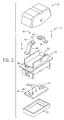
- the switch 12 generally includes an operating member 30, a switch frame 32 on which the operating member is mounted, a rear plate 34, and a printed circuit board (PCB) 36 positioned between the switch frame 32 and the rear plate 34.
- the operating member 30 is in the form of a rocker button that is movable by an operator between an off/neutral position and one or more activated positions, with the rocker button 30 rotating relative to the switch frame 32 responsive to actuation of the button by the operator.
- the switch 12 is constructed as a rocker switch having a neutral position and two activated positions - a first activated position and a second activated position.
- the rocker button 30 is moved to the first activated position and, if the user pushes the other side of the rocker button 30, the rocker button 30 is moved to the second activated position.
- LEDs 38 located on the PCB 36 provide illumination of graphic icons on the rockers 30 to provide a visual indication to the user of whether the rocker button 30 is in the neutral position, the first activated position or the second activated position.
- a radio-frequency identification (RFID) system 40 that includes at least one RFID tag 42, with each RFID tag 42 having data stored thereon regarding a unique identifier or address tying to the icon/function of the respective position of switch 12 - such that the switch 12 may function as a self-identifying switch.
- RFID radio-frequency identification
- the identifying data stored on the RFID tags 42 may tie/identify the switch position as functioning to control headlights, hazard lights, windshield wipers, rear windshield heating, cruise control functions, or internal central locking, for example.
- the switch 12 provided in FIG.
- the RFID system 40 is shown as including two RFID tags 42 therein - one RFID tag for each activated switch position - although it is recognized that only a single RFID tag 42 could be included in the switch 12.
- the RFID tags 42 may be affixed to the rocker button 30 on an underside thereof, such as via an adhesive, snap fit engagement, or other suitable means.
- Each of the RFID tags 42 contains an integrated circuit (IC) 44 for storing and processing information, modulating and demodulating an RF signal, and other specialized functions, as well as a non-volatile memory (not shown) for storing the tag information, and either fixed or programmable logic for processing the transmission and sensor data, respectively.
- the integrated circuit 44 also functions to collect DC power from radio energy transmitted by an RFID reader 56, although it is recognized that the RFID tags may instead be active tags or battery-assisted passive (BAP) tags, as will be explained in greater detail below.
- a switch contact 46 (i.e., contact terminal) is provided that allows for the RFID tag 42 to selectively communicate with a corresponding antenna 48 that, according to one embodiment, is affixed to the PCB 36. That is, a switch contact 46 is electrically coupled to each RFID tag 42 and is movable between "opened” and “closed” positions responsive to actuation of the rocker button 30, such that the contact 46 will selectively provide for a communication path between the RFID tag 42 and its respective antenna 48 when moved to the closed position- with openings 50 being formed in frame 32 to provide for connection of the switch contacts 46 and the antennas 48.
- a switch contact 46 When a switch contact 46 is closed, its respective RFID tag 42 will transmit the data stored thereon - i.e., a unique address tying to the icon/function of the switch - to the antenna 48, with the antenna 48 then functioning to send out a wireless signal that includes this data - referred to hereafter as a "switch message.”
- an antenna 48 is provided for each of the RFID tags 42, with each antenna 48 being in selective communication with its respective RFID tag 42; however, it is recognized that an alternative embodiment of the switch 12 could include only a single antenna 48 that would be utilized to broadcast signals for both of the RFID tags 42, with it being understood that no more than one of the RFID tags 42 would ever be in communication with the antenna 48 at any given time.
- the rocker button 30 is used in order to provide manual switching for the switch contacts 46.
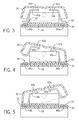
- the switch is shown in each of the neutral position, first activated position and second activated position, with the positioning of the switch contacts 46 relative to antennas 48 being illustrated therein.
- FIG. 3 when the rocker button 30 is in the neutral position, then the two switch contacts 46a, 46b are in the switched-off state - separated from antennas 48a, 48b - such that no communication path is provided from the RFID tags 42a, 42b to their respective antennas 48a, 48b.
- the rocker button 30 if the user pushes one side of the rocker button 30, the rocker button 30 is moved to a first activated position and, in consequence, a first RFID tag 42a and first switch contact 46a on the rocker button 30 are caused to translate downward such that the first switch contact 46a is electrically coupled to the first antenna 48a, such that the data stored on the RFID tag is provided to the antenna 48a and the antenna 48a transmits a wireless switch message that includes the data from the first RFID tag 42a. As shown in FIG.
- the second RFID tag 42b and second switch contact 46b are caused to translate downward such that the second switch contact 46b is electrically coupled to the second antenna 48b, such that the data stored on the RFID tag 42b is provided to the antenna 48b and the antenna 48b transmits a wireless switch message that includes the data from the second RFID tag 42b.
- switches 12 in switch module 10 are shown and described in FIGS. 2-5 as being rocker switches having a neutral position and two activated positions, it is recognized that the switches 12 could also be constructed as rocker switches having only a neutral/off position and one activated/on position. In such an embodiment, only a single RFID tag 42 and switch contact 46 would be employed - with the switch contact 46 selectively connecting with an antenna 48 to provide a communication path between the RFID tag 42 and the antenna 48. Construction of a switch 12 as a pushbutton switch or toggle switch would similarly operate with there being only a single RFID tag 42 and switch contact 46, and a single respective antenna 48.
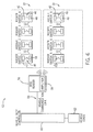
- the vehicle communication system 52 includes one or more switch modules 10 each having a plurality of switches 12 therein - such as shown and described in FIGS. 1 and 2 - operatively connected to and in communication with a vehicle communication network or link 54, such as a CAN bus or LIN bus for example. That is, the switch modules 10 and switches 12 therein are multiplexed with the vehicle communication network or link 54 communication device (using a CAN or LIN protocol, for example) to interface with other devices on the vehicle.
- a vehicle communication network or link 54 such as a CAN bus or LIN bus for example.
- an RFID reader 56 is operably coupled to the communication link 54 that interacts with the switches 12 to receive information therefrom, with the RFID reader 56 being mountable on the vehicle chassis.
- the RFID reader 56 and RFID tags 42 in switches 12 are provided as an Active Reader Passive Tag (ARPT) system - in which the RFID reader 56 transmits interrogator signals and receives authentication replies (in the form of switch messages) from passive RFID tags 42.
- ARPT Active Reader Passive Tag
- the RFID reader 56 In addition to interrogating the RFID tags 42 in order to receive authentication replies therefrom, the RFID reader 56 also functions to power/charge the RFID tags 42.
- the RFID reader 56 includes an antenna amplifier 58 that functions to selectively boost the strength of signals transmitted therefrom to the RFID tags 42, with a boosted "charging signal" being, for example, up to roughly a thousand times stronger than the interrogation signals transmitted by the RFID reader 56.
- the RFID tags 42 use the radio energy in the charging signals to charge components therein, such as the integrated circuit 44 of the RFID tag 42.
- RFID tags 42 and RFID reader 56 are described above as an ARPT system in which the RFID reader 56 transmits interrogator signals and receives authentication replies from passive RFID tags 42, it is recognized that alternative embodiments could instead provide the RFID tags as active tags or battery-assisted passive (BAP) tags.
- BAP battery-assisted passive
- the RFID tags 42 When provided as active tags having an on-board battery, the RFID tags 42 periodically transmit switch messages out therefrom - i.e., transmit switch messages when their respective switch 12 is in an activated position and the RFID tag 42 is in communication with its antenna 48.
- BAP tags the RFID tags 42 have a small battery on-board and are activated only when interrogated by the RFID reader 56.
- the RFID reader 56 periodically scans the system 52 checking for the presence of RFID tags, with the RFID reader 56 transmitting an encoded radio signal to interrogate RFID tags 42 in the switches 12 of switch modules 10.
- the RFID reader 56 detects a switch closure (i.e., a switch in an activated position) by detecting the presence of the RFID tags 42 responsive to the interrogation signal.
- a switch closure is only detected when the switch contact 46 is in a closed position that connects an antenna 48 to its respective RFID tag 42, with the closure of the switch contact 46 being based on the position of the rocker button 30 of the switch 12. Accordingly, the system logic used by the RFID reader 56 in interrogating the RFID tags 42 would be set forth simply as:
- RFID tags 42 that are connected to an antenna 48 by its respective switch contact 46 respond to the RFID reader 56 with a switch message that includes their identification and switch state information, with the RFID reader 56 receiving a switch message from each RFID tag 42 whose switch 12 is in an activated position.
- the RFID reader 56 can discriminate among several RFID tags 42 that might be within the range of the RFID reader 56 and read them simultaneously.
- the switch messages received by the RFID reader 56 are provided to the vehicle communication link 54 and a serial message is sent on the communication link.
- the serial message contains the switch identifier and the switch state for each switch message received from the RFID tags 42.
- the vehicle communication link 54 provides the serial message to a vehicle body controller 60 (i.e., CAN/LIN master controller), with the vehicle body controller 60 interpreting switch messages received from the switches 12 - via RFID reader 56 - and transmitting a command to the vehicle function/load 62, so as to cause the vehicle function/load to operate in a desired manner - such as sending a command to cause windshield wipers to turn-on.
- a vehicle body controller 60 i.e., CAN/LIN master controller
- the switch modules 10 can operate within vehicle communication system 52 to identify the presence of a particular switch 12 and the switch's state.
- any of "Rocker Switch 1" thru “Rocker Switch 8" could be individually identified to associate an individual identification to each switch 12 and a state of each switch 12.
- each switch 12 contains a unique address/identifier associated with the switch function, with such address information being stored on the RFID tag(s) 42 included in the switch 12.
- the RFID reader 56 receives switch messages from the RFID tags 42 that contains the switch's address/identifier as well as the switch's logic state, and provides these messages in serial to the vehicle body controller 60, such that the vehicle body controller 60 interprets the switch messages for controlling/turning on an associated load/output 62.
- each RFID tag 42 on a switch 12 contains a unique identifier and the RFID reader 56 receives signals from the RFID tags 42 that include these identifiers, an OEM can place a switch 12 in any position on a vehicle dashboard 14 without changing the switch's functionality. For example, swapping the positions of "Rocker Switch 2" with “Rocker Switch 7" would have no effect on the switches' functionality or the associated system/module wiring. Regardless of the location of Rocker Switch 2, for example, the RFID reader 56 would recognize that it is receiving a switch message from Rocker Switch 2 and that the switch is in either the first activated position or the second activated position, and would relay that information to the vehicle communication link 54 and turn on the appropriate load/output device 62 by way of the vehicle's body controller 60.
- RFID tag may be incorporated into control systems or circuits that include limit switches and/or intrinsic safety switches in order to beneficially enable identification of an operational state of such switches.
- Limit switches With respect to limit switches, it is known that such switches are used in a variety of applications and environments because of their ruggedness, ease of installation, and reliability of operation, with the switches being operated by the motion of a machine part (e.g., the passing, positioning, and/or end of travel of an object) or presence of an object and are used for controlling machinery as part of a control system, for example.
- Limit switches may take a variety of forms, such as an electromechanical device that consists of an actuator mechanically linked to one or more contacts such that, when an object comes into contact with the actuator, the device operates the contacts to make or break an electrical connection.
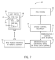
- FIG. 7 a schematic diagram of a limit switch control system 64 is shown according to an embodiment of the invention.
- the limit switch control system 64 is employed, for example, to prevent a field device 66 from moving beyond its normal stop position or operating range.
- the control system 64 of FIG. 7 includes a limit switch 68 and a control circuit 70 in communication therewith that is configured to control operation of the field device 66.
- the limit switch 68 may, for example, be in the form of a spring loaded limit switch or a reed switch.
- the limit switch 68 is positioned so that its contact 72 opens when a feature/component of the field device 66 engages the limit switch 68, thereby opening limit switch 68.
- the limit switch 68 opens, the change in switch state is provided to the control circuit 70 for purposes of controlling the field device 66, such as stopping movement of the field device 66, for example.
- an RFID tag 42 is provided for the limit switch 68 that functions to provide for remote determination of a switch state (and thus the position of the movable field device) and provide information on the field device 66 (e.g., device control number, device name, type, manufacturer name, manufactured date, etc.). That is, in certain applications or operating environments, it may be desirable to incorporate an RFID tag 42 into the limit switch 68. As one example, in the use of limit switches 68 in caustic environments (highly acidic, etc.) there is risk of wire corrosion, limited contact life, intermittent operation, etc., that can raise costs and compromise system operation.
- the RFID tag 42 contains an integrated circuit (IC) 44 for storing and processing information, modulating and demodulating an RF signal, and other specialized functions, as well as a non-volatile memory (not shown) for storing the tag information, and either fixed or programmable logic for processing the transmission and sensor data, respectively.
- the integrated circuit 44 also functions to collect DC power from radio energy transmitted by an RFID reader 56, although it is recognized that the RFID tags may instead be active tags or battery-assisted passive (BAP) tags.
- BAP battery-assisted passive
- the RFID tag 42 is an active tag, the tag incorporates a transceiver connecting a battery with the antenna so as to enable the tag to communicate with an RFID reader 56 at a greater distance.
- the RFID tag 42 selectively communicates with a corresponding antenna 48 based on the positioning of the switch contact 72 (i.e., contact terminal) of limit switch 68. That is, the switch contact 72 is movable between “opened” and “closed” positions responsive to actuation of the limit switch 68 in order to selectively provide for a communication path between the RFID tag 42 and its respective antenna 48 when moved to the closed position.
- the switch contact 72 When the switch contact 72 is closed, the RFID tag 42 will transmit to the antenna 48, with the antenna 48 then functioning to send out a wireless signal that includes the switch state of the limit switch 68 - and thus consequently the position/state of the field device 66.
- the wireless signal is received by an RFID reader 56 that is in operable communication with the antenna 48 and located remotely therefrom, with the RFID reader being operably coupled to the control circuit 70 to provide information thereto regarding the operational state of the limit switch.
- the control circuit may comprise a microcontroller 74 and system control equipment 76, with the RFID reader 56 providing a data message to the microcontroller 74 (such as in the form of serial communication, TTL communication, or another suitable communication mode/format) that contains a limit switch identifier and the switch state for a switch message received from the RFID tag 42.
- the microcontroller 74 may then transfer data to the system control equipment 76 via a communication or control data interface (i.e., communications link), in order to provide for control of the field device 66 via the system control equipment 76.
- a potting 78 may be provided about the limit switch 68 to provide protection to the limit switch 68 and its associated RFID tag 42 and antenna 48.
- the potting 78 serves to protect the switch contact 72 and thus improve reliability and life thereof and it is recognized that implementation of the RFID tag 42 with the limit switch 68 and the wireless communication provided thereby (as opposed to wiring running to the switch) allows for the limit switch 68 to be completely sealed within the potting 78.
- a limit switch 68 in the form of a spring loaded limit switch or a reed switch would be particularly well suited.
- intrinsic safety circuits are circuits designed to provide for safe operation of electrical equipment in hazardous areas by limiting the energy available for ignition (i.e., operate with low currents and voltages). Areas with dangerous concentrations of flammable gases or dust are found in applications such as gas furnaces, petrochemical refineries and mines.
- a device termed intrinsically safe is designed to be incapable of producing heat or spark sufficient to ignite an explosive atmosphere.
- intrinsically safe electronics devices reducing or eliminating internal sparking, controlling component temperatures, and eliminating component spacing that would allow dust to short a circuit.
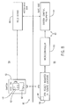
- the safety circuit 80 includes a switch 82 - in the form of a hand operated switch or a limit switch, for example - used to sense a condition of or control operation of a field device 84 and a control circuit 86 in communication therewith that is configured to control operation of the field device 84.
- the limit switch 68 includes a switch contact 88 that is opened/closed manually (when a hand operated switch) or that is opened closed responsive to a position or state of the field device 84 (when a limit switch) 68.
- the position/state of the switch 82 in its opened or closed position is provided to the control circuit 86 for purposes of controlling the field device 84 and, as shown in FIG. 8 , communication of such information is provided to the control circuit wirelessly.
- An RFID tag 42 is provided for the switch 82 (and incorporated therein) that functions to provide for remote determination of a switch state (and thus the position/state of the field device) and provide information on the field device 84 (e.g., device control number, device name, type, manufacturer name, manufactured date, etc.).
- the RFID tag 42 contains an integrated circuit (IC) 44 for storing and processing information, modulating and demodulating an RF signal, and other specialized functions, as well as a non-volatile memory (not shown) for storing the tag information, and either fixed or programmable logic for processing the transmission and sensor data, respectively.
- the RFID tag 42 selectively communicates with a corresponding antenna 48 based on the positioning of the switch contact 88 (i.e., contact terminal) of the switch 82. That is, the switch contact 88 is movable between "opened” and “closed” positions responsive to actuation of the switch 82 in order to selectively provide for a communication path between the RFID tag 42 and its respective antenna 48 when moved to the closed position.
- the switch contact 88 When the switch contact 88 is closed, the RFID tag 42 will transmit to the antenna 48, with the antenna 48 then functioning to send out a wireless signal that includes the switch state of the switch 82 - and thus consequently the position/state of the field device 84.
- the wireless signal is received by an RFID reader 56 that is in operable communication with the antenna 48 and located remotely therefrom, with the RFID reader being operably coupled to the control circuit 86 to provide information thereto regarding the operational state of the switch 82.
- the control circuit may comprise a microcontroller 90 and system control equipment 92, with the RFID reader 56 providing a data message to the microcontroller 90 that contains a switch identifier and the switch state for a switch message received from the RFID tag 42.
- the microcontroller 90 may then transfer data to the system control equipment 92 via a communication or control data interface (i.e., communications link), in order to provide for control of the field device 84 via the system control equipment 92.
- the switch 82 is located in a hazardous environment 94 in which intrinsic safety precautions must be undertaken - such as an environment where gas fumes, hydrogen, or other ignitable/flammable gasses/materials are present.
- the RFID reader 56 and an antenna amplifier 58 therein
- control circuit 86 are located in a "safe" environment 96 - such as in a remote location far from the intrinsic safety control system 80.
- the power in or provided to the RFID tag 42 is limited such that it remains below prescribed voltage and current intrinsic safety limits.
- the incorporation of the RFID tag 42 and antenna 48 in the switch 82 allows for isolation of the switch and the elimination of wiring thereto that could short out and causing an arc in the hazardous environment 94.
- use of the switch 82 and associated RFID tag 42 (and antenna 48) in the intrinsic safety control system 80 may negate the need for any special wiring and/or amplification to limit energy levels that is typically associated with existing safety circuits. Accordingly use of a switch 82 with an associated RFID tag 42 can reduce overall cost of the intrinsic safety control system 80.
- a control system for controlling operation of a field device includes a switch having a switch contact movable between an off position and an activated position, a radio frequency identification (RFID) tag integrated with the switch and in selective communication with the switch based on the position thereof, an RFID reader configured to receive switch messages from the RFID tag that indicate an operational state of the switch, and a control circuit configured to receive switch messages from the RFID reader, the control circuit receiving the switch messages for purposes of controlling the field device.
- RFID radio frequency identification
- the limit switch control system also includes a radio frequency identification (RFID) tag integrated with the limit switch, the RFID tag including thereon a unique identifier tied to a function of the limit switch in its activated position.
- RFID radio frequency identification
- the limit switch control system further includes an antenna integrated with the limit switch and selectively in operable communication with the RFID tag based on a position of the switch contact, wherein a communications path between the RFID tag and the antenna is formed by the switch contact when the limit switch is in the activated position, thereby causing the antenna to transmit a switch signal to an RFID reader remote from the limit switch, the switch signal including therein the unique identifier of the RFID tag.
- the intrinsically safe control system also includes a control circuit in operable communication with the switch via transmission of the switch messages thereto, with the switch messages causing the control circuit to control operation of the field device.
Landscapes
- Engineering & Computer Science (AREA)
- Physics & Mathematics (AREA)
- Health & Medical Sciences (AREA)
- Toxicology (AREA)
- Electromagnetism (AREA)
- Computer Networks & Wireless Communication (AREA)
- General Health & Medical Sciences (AREA)
- Artificial Intelligence (AREA)
- Computer Vision & Pattern Recognition (AREA)
- General Physics & Mathematics (AREA)
- Theoretical Computer Science (AREA)
- Signal Processing (AREA)
- Selective Calling Equipment (AREA)
- Arrangements For Transmission Of Measured Signals (AREA)
Abstract
Description
- The present invention is a continuation-in-part of and claims priority to
U.S. Ser. No. 14/584,118, filed December 29, 2014 - Embodiments of the present invention relates generally to electrical switches for use in motor vehicles and, more particularly, to vehicle switches having a self-identifying switch function. The self-identifying feature of the switches enables the placement of switches in any of a number of locations consistent with a customer's desired switch customization requirement, while providing for the identification of a switch regardless of its location, such that switches can be placed in any position within a defined network on the vehicle without changing the switch's functionality or the system wiring.
- Additional embodiments of the present invention relate generally to electrical control switches and, more particularly, to electrical control switches having an radio frequency identification (RFID) tag incorporated therein. The incorporation of the RFID tag into the control switch provides benefits in implementations of the switch as a remote limit switch or an intrinsic safety switch.
- Electrical switches are used in motor vehicles as control switches for switching the motor vehicle lighting, the windshield wipers, the rear windshield heating, the cruise control functions, the internal central locking and other functions on and off. A number of such switches can be combined as control panels in the dashboard, in the center console or the like. In specialty vehicle markets - such as heavy trucks, agricultural equipment, and construction equipment, for example - many original equipment manufacturers (OEMs) produce custom dashboards for their customers. In doing so, the OEMs allow the customers to pick options as well as their associated switch locations. While such customization is desirable from the standpoint of the customer, such customization leads to significant overhead expenses for the OEMs with respect to managing customer options for the dashboards. That is, present methods of managing production for customer dashboards having customized options and associated switch locations requires separate drawings and wire harnesses for every vehicle manufactured. Furthermore, some OEMs may even install the wires for every option sold, but only connect the wires used with the individual customer dashboard order.
- In the mix of switch functions, some switches provide input signals to a vehicle's microprocessor-based controller, often referred to as a body controller, or electronic controller unit (ECU), which receives the signal and makes logic decisions regarding how that function is to be performed or activated. Other switches are wired directly to their intended loads. Those switches providing an ECU input typically operate at very low current, typically in the range of 5 to 20 milliAmperes (mA), whereas direct-wired switches may handle loads up to 20 Amperes or more. Different contact materials are needed to accommodate these varying load ranges, as well as different sized wires and connectors. The arrangement or rearrangement of switches within the dashboard array is often limited in practice by the ability of the OEM to provide appropriate high current and low current wiring to support the desired functions. It is also common for OEMs to provide the same type of electrical connector and wires for all switch positions for economy and standardization, though the practice can result in a higher percentage of wiring errors at the time the vehicle is being assembled.
- It is recognized that electrical control switches may be utilized in other environments beyond that of vehicle controls, and that electrical control switches may take a variety of other forms. Two common examples of electrical control switches include limit switches and intrinsic safety switches. With respect to limit switches, it is known that such switches are used in a variety of applications and environments because of their ruggedness, ease of installation, and reliability of operation, with the switches being operated by the motion of a machine part (e.g., the passing, positioning, and/or end of travel of an object) or presence of an object and are used for controlling machinery as part of a control system, for example. Limit switches may take a variety of forms, such as an electromechanical device that consists of an actuator mechanically linked to one or more contacts such that, when an object comes into contact with the actuator, the device operates the contacts to make or break an electrical connection. With respect to intrinsic safety circuits and switches, intrinsic safety circuits are circuits designed to provide for safe operation of electrical equipment in hazardous areas by limiting the energy available for ignition (i.e., operate with low currents and voltages). Areas with dangerous concentrations of flammable gases or dust are found in applications such as gas furnaces, petrochemical refineries and mines. A device termed intrinsically safe is designed to be incapable of producing heat or spark sufficient to ignite an explosive atmosphere. There are several considerations in designing intrinsically safe electronics devices: reducing or eliminating internal sparking, controlling component temperatures, and eliminating component spacing that would allow dust to short a circuit.
- It is recognized that, in the use of limit switches in caustic environments (highly acidic, etc.), there is risk of wire corrosion, limited contact life, intermittent operation, etc., that can raise costs and compromise system operation. Also, in the use of limit switches in remote applications or in rotating applications (e.g., on the inside of a carousel), there can be extensive cost in making electrical connections to the limit switch, as the costs of running wire to a remote limit switch through conduit may be prohibitive and/or the cost and reliability of a slip ring required for wiring in a rotating application may be similarly prohibitive. It is also recognized that, in the use of intrinsic safety switches, special wiring and/or amplification may be required to limit energy levels in the intrinsic safety system, which leads to increased costs related to the system.
- It would therefore be desirable to design a system that enables OEMs to reduce the cost of managing a custom dashboard. In doing so, the system and method would allow for dashboard customization without requiring the OEM to rewire/relocate the wire harnesses to accommodate the customization - thereby enabling vehicle OEMs to significantly reduce the engineering overhead and the wire count associated with a custom dashboard.
- It would also therefore be desirable to provide a control switch useable in remote locations and/or in hazardous environments (i.e., caustic environments or environments requiring intrinsically safety operation) that overcomes the aforementioned drawbacks.
- Embodiments of the present invention provide a vehicle control switches that provides a self-identifying switch function. The switches may be placed in any of a number of locations consistent with a customer's desired switch customization requirement, while providing for the identification of a switch regardless of its location, such that switches can be placed in any position within a defined network on the vehicle without changing the switch's functionality or the system wiring.
- Embodiments of the present invention also provide a control system for controlling operation of a field device located in a remote location or in a hazardous environment that requires intrinsically safe operation. The control system includes a switch having an radio frequency identification (RFID) tag associated therewith that provides for wireless communication to and from the switch.
- In accordance with one aspect of the invention, a control system for controlling operation of a field device includes a switch having a switch contact movable between an off position and an activated position, a radio frequency identification (RFID) tag integrated with the switch and in selective communication with the switch based on the position thereof, an RFID reader configured to receive switch messages from the RFID tag that indicate an operational state of the switch, and a control circuit configured to receive switch messages from the RFID reader, the control circuit receiving the switch messages for purposes of controlling the field device.
- In accordance with another aspect of the invention, a limit switch control system for controlling operation of a field device includes a limit switch including a switch contact movable between an off position and an activated position, the switch contact movable between the off position and the activated position responsive to a movement or positioning of the field device relative to the limit switch. The limit switch control system also includes a radio frequency identification (RFID) tag integrated with the limit switch, the RFID tag including thereon a unique identifier tied to a function of the limit switch in its activated position. The limit switch control system further includes an antenna integrated with the limit switch and selectively in operable communication with the RFID tag based on a position of the switch contact, wherein a communications path between the RFID tag and the antenna is formed by the switch contact when the limit switch is in the activated position, thereby causing the antenna to transmit a switch signal to an RFID reader remote from the limit switch, the switch signal including therein the unique identifier of the RFID tag.
- In accordance with yet another aspect of the invention, an intrinsically safe control system for controlling operation of a field device includes a switch having a switch contact movable between an off position and an activated position, a radio frequency identification (RFID) tag integrated with the switch, and an antenna operable with the RFID tag to transmit switch messages indicative of an operational state of the switch, wherein movement of the switch between the off position and the activated position selectively provides a communications path between the RFID tag and the antenna. The intrinsically safe control system also includes a control circuit in operable communication with the switch via transmission of the switch messages thereto, with the switch messages causing the control circuit to control operation of the field device.
- Various other features and advantages of the present invention will be made apparent from the following detailed description and the drawings.
- The drawings illustrate preferred embodiments presently contemplated for carrying out the invention.
- In the drawings:
-
FIG. 1 shows front and rear views of a self-identifying vehicle switch module, according to an embodiment of the invention. -
FIG. 2 is an exploded view of a switch included in the switch module ofFIG. 1 , according to an embodiment of the invention. -
FIGS. 3-5 illustrate a cross-sectional view of the switch ofFIG. 2 , with the switch in a neutral position, first activated position, and second activated position, respectively. -
FIG. 6 is a schematic block diagram of a vehicle communication system that includes a plurality of self-identifying vehicle switches, according to an embodiment of the invention. -
FIG. 7 is a schematic block diagram of a limit switch control system according to an embodiment of the invention. -
FIG. 8 is a schematic block diagram of an intrinsic safety control system according to an embodiment of the invention. - Embodiments of the invention are directed to vehicle control switches having a self-identifying switch function, and a vehicle communications system for detecting the switches. The self-identification feature of the switches enables the placement of switches in any of a number of locations within a defined vehicle network consistent with a customer's desired switch customization requirement, while providing for the identification of a switch regardless of its location, such that switches can be placed in any position on the vehicle within that network without changing the switch's functionality or the system wiring.
- Referring to
FIG. 1 , the general structure of aswitch module 10 having a plurality ofswitches 12 is shown according to an embodiment of the invention. Theswitch module 10 is incorporated as part of adashboard 14 in a motor vehicle, for example in a commercial vehicle, such as a goods vehicle. An operator of the vehicle uses theswitches 12 to operate various functions in the vehicle, such as for switching the motor vehicle lighting, the windshield wipers, the diesel fuel heating, or other specialized equipment on the vehicle. In the embodiment illustrated inFIG. 1 , theswitch module 10 comprises fourswitches 12; however, it is recognized that a greater or smaller number ofswitches 12 could be included in the module. For example, aswitch module 10 could be provided having eight switches 12 - arranged in a single row or in two rows of four, for example. While there is no limit on the number ofswitches 12 that can be included inswitch module 10, it is recognized that for practical purposes - such as responsiveness and speed of switch functioning - the number ofswitches 12 in anindividual module 10 will be limited to a reasonable number so as to maintain a minimum level of vehicle performance. - As further shown in
FIG. 1 , theswitches 12 ofswitch module 10 are received within amodule housing 16 that is fitted in thedashboard 14 of the motor vehicle. Thehousing 16 is formed as a generally hollow member configured to receive theindividual switches 12 therein and includes mating features formed thereon, such as alignment tabs orslots 18, which enable mating of theswitches 12 within thehousing 16 in the correct orientation. Aback surface 20 of theswitch module 10 includes apower receptacle 22 formed thereon for enabling powering of the module. - According to embodiments of the invention, the
switches 12 included inswitch module 10 are configured as self-identifying switches. That is, each of theswitches 12 includes data stored thereon regarding a unique address or identifier tying to the icon/function of the switch. Accordingly, theswitches 12 may be placed in any of a number of locations in amodule 10 and/or on thedashboard 14 consistent with a customer's desired switch customization requirement, while providing for the identification of aswitch 12 regardless of its location, such that switches can be placed in any position within a defined network on the vehicle without changing the switch's functionality or the system wiring. - Referring now to
FIG. 2 , an exploded view of anindividual switch 12 is shown in more detail. Theswitch 12 generally includes an operatingmember 30, aswitch frame 32 on which the operating member is mounted, arear plate 34, and a printed circuit board (PCB) 36 positioned between theswitch frame 32 and therear plate 34. According to an exemplary embodiment, the operatingmember 30 is in the form of a rocker button that is movable by an operator between an off/neutral position and one or more activated positions, with therocker button 30 rotating relative to theswitch frame 32 responsive to actuation of the button by the operator. In the embodiment ofFIG. 2 , theswitch 12 is constructed as a rocker switch having a neutral position and two activated positions - a first activated position and a second activated position. If the user pushes one side of therocker button 30, therocker button 30 is moved to the first activated position and, if the user pushes the other side of therocker button 30, therocker button 30 is moved to the second activated position. In one embodiment, light emitting diodes (LEDs) 38 located on thePCB 36 provide illumination of graphic icons on therockers 30 to provide a visual indication to the user of whether therocker button 30 is in the neutral position, the first activated position or the second activated position. - Also included in the
switch 12 is a radio-frequency identification (RFID)system 40 that includes at least oneRFID tag 42, with eachRFID tag 42 having data stored thereon regarding a unique identifier or address tying to the icon/function of the respective position of switch 12 - such that theswitch 12 may function as a self-identifying switch. For example, the identifying data stored on the RFID tags 42 may tie/identify the switch position as functioning to control headlights, hazard lights, windshield wipers, rear windshield heating, cruise control functions, or internal central locking, for example. According to the embodiment of theswitch 12 provided inFIG. 2 , theRFID system 40 is shown as including twoRFID tags 42 therein - one RFID tag for each activated switch position - although it is recognized that only asingle RFID tag 42 could be included in theswitch 12. In one embodiment, the RFID tags 42 may be affixed to therocker button 30 on an underside thereof, such as via an adhesive, snap fit engagement, or other suitable means. - Each of the RFID tags 42 contains an integrated circuit (IC) 44 for storing and processing information, modulating and demodulating an RF signal, and other specialized functions, as well as a non-volatile memory (not shown) for storing the tag information, and either fixed or programmable logic for processing the transmission and sensor data, respectively. In an embodiment where the RFID tags 42 are passive tags, i.e., the tags have no battery, the
integrated circuit 44 also functions to collect DC power from radio energy transmitted by anRFID reader 56, although it is recognized that the RFID tags may instead be active tags or battery-assisted passive (BAP) tags, as will be explained in greater detail below. - For each
RFID tag 42 inswitch 12, a switch contact 46 (i.e., contact terminal) is provided that allows for theRFID tag 42 to selectively communicate with a correspondingantenna 48 that, according to one embodiment, is affixed to thePCB 36. That is, aswitch contact 46 is electrically coupled to eachRFID tag 42 and is movable between "opened" and "closed" positions responsive to actuation of therocker button 30, such that thecontact 46 will selectively provide for a communication path between theRFID tag 42 and itsrespective antenna 48 when moved to the closed position- withopenings 50 being formed inframe 32 to provide for connection of theswitch contacts 46 and theantennas 48. When aswitch contact 46 is closed, itsrespective RFID tag 42 will transmit the data stored thereon - i.e., a unique address tying to the icon/function of the switch - to theantenna 48, with theantenna 48 then functioning to send out a wireless signal that includes this data - referred to hereafter as a "switch message." According to one embodiment of the invention, anantenna 48 is provided for each of the RFID tags 42, with eachantenna 48 being in selective communication with itsrespective RFID tag 42; however, it is recognized that an alternative embodiment of theswitch 12 could include only asingle antenna 48 that would be utilized to broadcast signals for both of the RFID tags 42, with it being understood that no more than one of the RFID tags 42 would ever be in communication with theantenna 48 at any given time. - In operation of
switch 12, therocker button 30 is used in order to provide manual switching for theswitch contacts 46. Referring toFIGS. 3-5 , the switch is shown in each of the neutral position, first activated position and second activated position, with the positioning of theswitch contacts 46 relative toantennas 48 being illustrated therein. As shown inFIG. 3 , when therocker button 30 is in the neutral position, then the twoswitch contacts antennas RFID tags respective antennas FIG. 4 , if the user pushes one side of therocker button 30, therocker button 30 is moved to a first activated position and, in consequence, afirst RFID tag 42a andfirst switch contact 46a on therocker button 30 are caused to translate downward such that thefirst switch contact 46a is electrically coupled to thefirst antenna 48a, such that the data stored on the RFID tag is provided to theantenna 48a and theantenna 48a transmits a wireless switch message that includes the data from thefirst RFID tag 42a. As shown inFIG. 5 , in a second activated position of therocker button 30, which is reached by pushing the other side of therocker button 30, thesecond RFID tag 42b andsecond switch contact 46b are caused to translate downward such that thesecond switch contact 46b is electrically coupled to thesecond antenna 48b, such that the data stored on theRFID tag 42b is provided to theantenna 48b and theantenna 48b transmits a wireless switch message that includes the data from thesecond RFID tag 42b. - While the
switches 12 inswitch module 10 are shown and described inFIGS. 2-5 as being rocker switches having a neutral position and two activated positions, it is recognized that theswitches 12 could also be constructed as rocker switches having only a neutral/off position and one activated/on position. In such an embodiment, only asingle RFID tag 42 andswitch contact 46 would be employed - with theswitch contact 46 selectively connecting with anantenna 48 to provide a communication path between theRFID tag 42 and theantenna 48. Construction of aswitch 12 as a pushbutton switch or toggle switch would similarly operate with there being only asingle RFID tag 42 andswitch contact 46, and a singlerespective antenna 48. - Referring now to
FIG. 6 , and with continued reference toFIGS. 1 and2 , a schematic diagram of avehicle communication system 52 is shown according to an embodiment of the invention. Thevehicle communication system 52 includes one ormore switch modules 10 each having a plurality ofswitches 12 therein - such as shown and described inFIGS. 1 and2 - operatively connected to and in communication with a vehicle communication network or link 54, such as a CAN bus or LIN bus for example. That is, theswitch modules 10 and switches 12 therein are multiplexed with the vehicle communication network or link 54 communication device (using a CAN or LIN protocol, for example) to interface with other devices on the vehicle. - To provide for communication between the
switches 12 and thecommunication link 54, anRFID reader 56 is operably coupled to thecommunication link 54 that interacts with theswitches 12 to receive information therefrom, with theRFID reader 56 being mountable on the vehicle chassis. In an exemplary embodiment, theRFID reader 56 andRFID tags 42 inswitches 12 are provided as an Active Reader Passive Tag (ARPT) system - in which theRFID reader 56 transmits interrogator signals and receives authentication replies (in the form of switch messages) from passive RFID tags 42. In addition to interrogating the RFID tags 42 in order to receive authentication replies therefrom, theRFID reader 56 also functions to power/charge the RFID tags 42. For performing such a charging operation, theRFID reader 56 includes anantenna amplifier 58 that functions to selectively boost the strength of signals transmitted therefrom to the RFID tags 42, with a boosted "charging signal" being, for example, up to roughly a thousand times stronger than the interrogation signals transmitted by theRFID reader 56. The RFID tags 42 use the radio energy in the charging signals to charge components therein, such as theintegrated circuit 44 of theRFID tag 42. - While the RFID tags 42 and
RFID reader 56 are described above as an ARPT system in which theRFID reader 56 transmits interrogator signals and receives authentication replies from passive RFID tags 42, it is recognized that alternative embodiments could instead provide the RFID tags as active tags or battery-assisted passive (BAP) tags. When provided as active tags having an on-board battery, the RFID tags 42 periodically transmit switch messages out therefrom - i.e., transmit switch messages when theirrespective switch 12 is in an activated position and theRFID tag 42 is in communication with itsantenna 48. When provided as BAP tags, the RFID tags 42 have a small battery on-board and are activated only when interrogated by theRFID reader 56. - In operation, the
RFID reader 56 periodically scans thesystem 52 checking for the presence of RFID tags, with theRFID reader 56 transmitting an encoded radio signal to interrogateRFID tags 42 in theswitches 12 ofswitch modules 10. TheRFID reader 56 then detects a switch closure (i.e., a switch in an activated position) by detecting the presence of the RFID tags 42 responsive to the interrogation signal. A switch closure is only detected when theswitch contact 46 is in a closed position that connects anantenna 48 to itsrespective RFID tag 42, with the closure of theswitch contact 46 being based on the position of therocker button 30 of theswitch 12. Accordingly, the system logic used by theRFID reader 56 in interrogating the RFID tags 42 would be set forth simply as: - Switch contact closure is TRUE when the RFID reader reports the presence of the RFID tag.
- Switch contact closure is FALSE when the RFID reader does not report the presence of the RFID tag.
- Those RFID tags 42 that are connected to an
antenna 48 by itsrespective switch contact 46 respond to theRFID reader 56 with a switch message that includes their identification and switch state information, with theRFID reader 56 receiving a switch message from eachRFID tag 42 whoseswitch 12 is in an activated position. As each of the RFID tags 42 has an individual identification or serial number, theRFID reader 56 can discriminate amongseveral RFID tags 42 that might be within the range of theRFID reader 56 and read them simultaneously. - After running the RFID scan, the switch messages received by the
RFID reader 56 are provided to thevehicle communication link 54 and a serial message is sent on the communication link. The serial message contains the switch identifier and the switch state for each switch message received from the RFID tags 42. As shown inFIG. 3 , thevehicle communication link 54 provides the serial message to a vehicle body controller 60 (i.e., CAN/LIN master controller), with thevehicle body controller 60 interpreting switch messages received from the switches 12 - via RFID reader 56 - and transmitting a command to the vehicle function/load 62, so as to cause the vehicle function/load to operate in a desired manner - such as sending a command to cause windshield wipers to turn-on. - According to embodiments of the invention, the
switch modules 10 can operate withinvehicle communication system 52 to identify the presence of aparticular switch 12 and the switch's state. Thus, as indicated inFIG. 6 for example, any of "Rocker Switch 1" thru "Rocker Switch 8" could be individually identified to associate an individual identification to eachswitch 12 and a state of eachswitch 12. As indicated previously, eachswitch 12 contains a unique address/identifier associated with the switch function, with such address information being stored on the RFID tag(s) 42 included in theswitch 12. TheRFID reader 56 receives switch messages from the RFID tags 42 that contains the switch's address/identifier as well as the switch's logic state, and provides these messages in serial to thevehicle body controller 60, such that thevehicle body controller 60 interprets the switch messages for controlling/turning on an associated load/output 62. - Because each
RFID tag 42 on aswitch 12 contains a unique identifier and theRFID reader 56 receives signals from the RFID tags 42 that include these identifiers, an OEM can place aswitch 12 in any position on avehicle dashboard 14 without changing the switch's functionality. For example, swapping the positions of "Rocker Switch 2" with "Rocker Switch 7" would have no effect on the switches' functionality or the associated system/module wiring. Regardless of the location ofRocker Switch 2, for example, theRFID reader 56 would recognize that it is receiving a switch message fromRocker Switch 2 and that the switch is in either the first activated position or the second activated position, and would relay that information to thevehicle communication link 54 and turn on the appropriate load/output device 62 by way of the vehicle'sbody controller 60. - While embodiments described above make use of the RFID tag to provide a self-identifying vehicle control switch (provided on a vehicle dashboard) whose function and operational state is identifiable, it is recognized that additional embodiments of the invention may encompass other types of control systems and circuits that make use of RFID tags to provide for identification of an operational state of a switch. For example, an RFID tag may be incorporated into control systems or circuits that include limit switches and/or intrinsic safety switches in order to beneficially enable identification of an operational state of such switches.
- With respect to limit switches, it is known that such switches are used in a variety of applications and environments because of their ruggedness, ease of installation, and reliability of operation, with the switches being operated by the motion of a machine part (e.g., the passing, positioning, and/or end of travel of an object) or presence of an object and are used for controlling machinery as part of a control system, for example. Limit switches may take a variety of forms, such as an electromechanical device that consists of an actuator mechanically linked to one or more contacts such that, when an object comes into contact with the actuator, the device operates the contacts to make or break an electrical connection.
- Referring to
FIG. 7 , a schematic diagram of a limitswitch control system 64 is shown according to an embodiment of the invention. The limitswitch control system 64 is employed, for example, to prevent afield device 66 from moving beyond its normal stop position or operating range. Thecontrol system 64 ofFIG. 7 includes alimit switch 68 and acontrol circuit 70 in communication therewith that is configured to control operation of thefield device 66. According to embodiments of the invention, thelimit switch 68 may, for example, be in the form of a spring loaded limit switch or a reed switch. Thelimit switch 68 is positioned so that itscontact 72 opens when a feature/component of thefield device 66 engages thelimit switch 68, thereby openinglimit switch 68. When thelimit switch 68 opens, the change in switch state is provided to thecontrol circuit 70 for purposes of controlling thefield device 66, such as stopping movement of thefield device 66, for example. - As further shown in
FIG. 7 , anRFID tag 42 is provided for thelimit switch 68 that functions to provide for remote determination of a switch state (and thus the position of the movable field device) and provide information on the field device 66 (e.g., device control number, device name, type, manufacturer name, manufactured date, etc.). That is, in certain applications or operating environments, it may be desirable to incorporate anRFID tag 42 into thelimit switch 68. As one example, in the use oflimit switches 68 in caustic environments (highly acidic, etc.) there is risk of wire corrosion, limited contact life, intermittent operation, etc., that can raise costs and compromise system operation. As additional examples, in remote applications or in rotating applications (e.g., on the inside of a carousel), there can be extensive cost in making electrical connections to thelimit switch 68, as the costs of running wire to a remote limit switch through conduit may be prohibitive and/or the cost and reliability of a slip ring required for wiring in a rotating application may be similarly prohibitive. - The
RFID tag 42 contains an integrated circuit (IC) 44 for storing and processing information, modulating and demodulating an RF signal, and other specialized functions, as well as a non-volatile memory (not shown) for storing the tag information, and either fixed or programmable logic for processing the transmission and sensor data, respectively. In an embodiment where the RFID tags 42 are passive tags, i.e., the tags have no battery, theintegrated circuit 44 also functions to collect DC power from radio energy transmitted by anRFID reader 56, although it is recognized that the RFID tags may instead be active tags or battery-assisted passive (BAP) tags. In an embodiment where theRFID tag 42 is an active tag, the tag incorporates a transceiver connecting a battery with the antenna so as to enable the tag to communicate with anRFID reader 56 at a greater distance. - For the
RFID tag 42 associated withlimit switch 68, it is seen that theRFID tag 42 selectively communicates with a correspondingantenna 48 based on the positioning of the switch contact 72 (i.e., contact terminal) oflimit switch 68. That is, theswitch contact 72 is movable between "opened" and "closed" positions responsive to actuation of thelimit switch 68 in order to selectively provide for a communication path between theRFID tag 42 and itsrespective antenna 48 when moved to the closed position. When theswitch contact 72 is closed, theRFID tag 42 will transmit to theantenna 48, with theantenna 48 then functioning to send out a wireless signal that includes the switch state of the limit switch 68 - and thus consequently the position/state of thefield device 66. The wireless signal is received by anRFID reader 56 that is in operable communication with theantenna 48 and located remotely therefrom, with the RFID reader being operably coupled to thecontrol circuit 70 to provide information thereto regarding the operational state of the limit switch. In one embodiment, the control circuit may comprise amicrocontroller 74 andsystem control equipment 76, with theRFID reader 56 providing a data message to the microcontroller 74 (such as in the form of serial communication, TTL communication, or another suitable communication mode/format) that contains a limit switch identifier and the switch state for a switch message received from theRFID tag 42. Themicrocontroller 74 may then transfer data to thesystem control equipment 76 via a communication or control data interface (i.e., communications link), in order to provide for control of thefield device 66 via thesystem control equipment 76. - In an embodiment where the limit
switch control system 64 is employed in a caustic environment or exposed to inclement operating conditions, apotting 78 may be provided about thelimit switch 68 to provide protection to thelimit switch 68 and its associatedRFID tag 42 andantenna 48. The potting 78 serves to protect theswitch contact 72 and thus improve reliability and life thereof and it is recognized that implementation of theRFID tag 42 with thelimit switch 68 and the wireless communication provided thereby (as opposed to wiring running to the switch) allows for thelimit switch 68 to be completely sealed within thepotting 78. In an embodiment where such apotting 78 is provided, it is recognized that alimit switch 68 in the form of a spring loaded limit switch or a reed switch would be particularly well suited. - With respect to intrinsic safety circuits and switches, intrinsic safety circuits are circuits designed to provide for safe operation of electrical equipment in hazardous areas by limiting the energy available for ignition (i.e., operate with low currents and voltages). Areas with dangerous concentrations of flammable gases or dust are found in applications such as gas furnaces, petrochemical refineries and mines. A device termed intrinsically safe is designed to be incapable of producing heat or spark sufficient to ignite an explosive atmosphere. There are several considerations in designing intrinsically safe electronics devices: reducing or eliminating internal sparking, controlling component temperatures, and eliminating component spacing that would allow dust to short a circuit.
- Referring now to
FIG. 8 , an intrinsicsafety control system 80 is shown according to an embodiment of the invention. Thesafety circuit 80 includes a switch 82 - in the form of a hand operated switch or a limit switch, for example - used to sense a condition of or control operation of afield device 84 and acontrol circuit 86 in communication therewith that is configured to control operation of thefield device 84. Thelimit switch 68 includes aswitch contact 88 that is opened/closed manually (when a hand operated switch) or that is opened closed responsive to a position or state of the field device 84 (when a limit switch) 68. - The position/state of the
switch 82 in its opened or closed position is provided to thecontrol circuit 86 for purposes of controlling thefield device 84 and, as shown inFIG. 8 , communication of such information is provided to the control circuit wirelessly. AnRFID tag 42 is provided for the switch 82 (and incorporated therein) that functions to provide for remote determination of a switch state (and thus the position/state of the field device) and provide information on the field device 84 (e.g., device control number, device name, type, manufacturer name, manufactured date, etc.). TheRFID tag 42 contains an integrated circuit (IC) 44 for storing and processing information, modulating and demodulating an RF signal, and other specialized functions, as well as a non-volatile memory (not shown) for storing the tag information, and either fixed or programmable logic for processing the transmission and sensor data, respectively. TheRFID tag 42 selectively communicates with a correspondingantenna 48 based on the positioning of the switch contact 88 (i.e., contact terminal) of theswitch 82. That is, theswitch contact 88 is movable between "opened" and "closed" positions responsive to actuation of theswitch 82 in order to selectively provide for a communication path between theRFID tag 42 and itsrespective antenna 48 when moved to the closed position. When theswitch contact 88 is closed, theRFID tag 42 will transmit to theantenna 48, with theantenna 48 then functioning to send out a wireless signal that includes the switch state of the switch 82 - and thus consequently the position/state of thefield device 84. - The wireless signal is received by an
RFID reader 56 that is in operable communication with theantenna 48 and located remotely therefrom, with the RFID reader being operably coupled to thecontrol circuit 86 to provide information thereto regarding the operational state of theswitch 82. In one embodiment, the control circuit may comprise amicrocontroller 90 andsystem control equipment 92, with theRFID reader 56 providing a data message to themicrocontroller 90 that contains a switch identifier and the switch state for a switch message received from theRFID tag 42. Themicrocontroller 90 may then transfer data to thesystem control equipment 92 via a communication or control data interface (i.e., communications link), in order to provide for control of thefield device 84 via thesystem control equipment 92. - As shown in
FIG. 8 , theswitch 82 is located in ahazardous environment 94 in which intrinsic safety precautions must be undertaken - such as an environment where gas fumes, hydrogen, or other ignitable/flammable gasses/materials are present. Meanwhile, the RFID reader 56 (and anantenna amplifier 58 therein) andcontrol circuit 86 are located in a "safe" environment 96 - such as in a remote location far from the intrinsicsafety control system 80. In a hazardous location/environment, the power in or provided to theRFID tag 42 is limited such that it remains below prescribed voltage and current intrinsic safety limits. The incorporation of theRFID tag 42 andantenna 48 in theswitch 82 allows for isolation of the switch and the elimination of wiring thereto that could short out and causing an arc in thehazardous environment 94. - Beneficially, use of the
switch 82 and associated RFID tag 42 (and antenna 48) in the intrinsicsafety control system 80 may negate the need for any special wiring and/or amplification to limit energy levels that is typically associated with existing safety circuits. Accordingly use of aswitch 82 with an associatedRFID tag 42 can reduce overall cost of the intrinsicsafety control system 80. - Therefore, according to one embodiment of the present invention, a control system for controlling operation of a field device includes a switch having a switch contact movable between an off position and an activated position, a radio frequency identification (RFID) tag integrated with the switch and in selective communication with the switch based on the position thereof, an RFID reader configured to receive switch messages from the RFID tag that indicate an operational state of the switch, and a control circuit configured to receive switch messages from the RFID reader, the control circuit receiving the switch messages for purposes of controlling the field device.
- According to another embodiment of the present invention, a limit switch control system for controlling operation of a field device includes a limit switch including a switch contact movable between an off position and an activated position, the switch contact movable between the off position and the activated position responsive to a movement or positioning of the field device relative to the limit switch. The limit switch control system also includes a radio frequency identification (RFID) tag integrated with the limit switch, the RFID tag including thereon a unique identifier tied to a function of the limit switch in its activated position. The limit switch control system further includes an antenna integrated with the limit switch and selectively in operable communication with the RFID tag based on a position of the switch contact, wherein a communications path between the RFID tag and the antenna is formed by the switch contact when the limit switch is in the activated position, thereby causing the antenna to transmit a switch signal to an RFID reader remote from the limit switch, the switch signal including therein the unique identifier of the RFID tag.
- According to yet another embodiment of the present invention, an intrinsically safe control system for controlling operation of a field device includes a switch having a switch contact movable between an off position and an activated position, a radio frequency identification (RFID) tag integrated with the switch, and an antenna operable with the RFID tag to transmit switch messages indicative of an operational state of the switch, wherein movement of the switch between the off position and the activated position selectively provides a communications path between the RFID tag and the antenna. The intrinsically safe control system also includes a control circuit in operable communication with the switch via transmission of the switch messages thereto, with the switch messages causing the control circuit to control operation of the field device.
- The present invention has been described in terms of the preferred embodiment, and it is recognized that equivalents, alternatives, and modifications, aside from those expressly stated, are possible and within the scope of the appending claims.
Claims (20)
- A control system for controlling operation of a field device, the control system comprising:a switch having a switch contact movable between an off position and an activated position;a radio frequency identification (RFID) tag integrated with the switch and in selective communication with the switch based on the position thereof;an RFID reader configured to receive switch messages from the RFID tag that indicate an operational state of the switch; anda control circuit configured to receive switch messages from the RFID reader, the control circuit receiving the switch messages for purposes of controlling the field device.
- The control system of claim 1 further comprising an antenna integrated with the switch and selectively in operable communication with the RFID tag based on the position of the switch contact.
- The control system of claim 2 wherein the switch contact forms a communications path between the RFID tag and the antenna when in the activated position; and
wherein the antenna generates a switch message for transmission to the RFID reader when the communications path is formed between the RFID tag and the antenna. - The control system of claim 3 wherein the switch comprises a limit switch whose switch contact moves between the off position and the activated position based on a movement of the field device relative to the limit switch.
- The control system of claim 4 wherein the limit switch comprises a spring loaded limit switch or a reed switch.
- The control system of claim 1 further comprising a potting housing the switch and the RFID tag, so as to protect the switch and the RFID tag from a caustic environment.
- The control system of claim 1 wherein the control system comprises an intrinsically safe control system, with the switch and the RFID tag being located in a hazardous environment and the RFID reader and control circuit being located in an intrinsically safe environment.
- The control system of claim 7 wherein power in or provided to the RFID tag is limited such that it remains below prescribed voltage and current intrinsic safety limits.
- The control system of claim 1 wherein the RFID reader transmits interrogator signals to the RFID tag, with the RFID tag generating switch messages responsive to the interrogator signals.
- The control system of claim 1 wherein the RFID tag includes thereon a unique identifier tied to a function of the switch, with each switch message received by the RFID reader including the unique identifier of the RFID tag.
- A limit switch control system for controlling operation of a field device, the limit switch control system comprising:a limit switch including a switch contact movable between an off position and an activated position, the switch contact movable between the off position and the activated position responsive to a movement or positioning of the field device relative to the limit switch;a radio frequency identification (RFID) tag integrated with the limit switch, the RFID tag including thereon a unique identifier tied to a function of the limit switch in its activated position; andan antenna integrated with the limit switch and selectively in operable communication with the RFID tag based on a position of the switch contact;wherein a communications path between the RFID tag and the antenna is formed by the switch contact when the limit switch is in the activated position, thereby causing the antenna to transmit a switch signal to an RFID reader remote from the limit switch, the switch signal including therein the unique identifier of the RFID tag.
- The limit switch control system of claim 11 wherein the limit switch comprises a spring loaded limit switch or a reed switch.
- The limit switch control system of claim 11 further comprising a potting housing the limit switch, the RFID tag and the antenna so as to protect the limit switch, the RFID tag and the antenna from a caustic environment.
- The limit switch control system of claim 11 wherein the RFID tag comprises an active tag configured to communicate with the RFID reader from a remote location.
- The limit switch control system of claim 12 wherein the switch signal transmitted to the RFID reader from the RFID tag comprises a data message transmittable on a communications link connected to the RFID reader.
- An intrinsically safe control system for controlling operation of a field device, the intrinsically safe control system comprising:a switch having a switch contact movable between an off position and an activated position;a radio frequency identification (RFID) tag integrated with the switch;an antenna operable with the RFID tag to transmit switch messages indicative of an operational state of the switch, wherein movement of the switch between the off position and the activated position selectively provides a communications path between the RFID tag and the antenna;a control circuit in operable communication with the switch via transmission of the switch messages thereto, with the switch messages causing the control circuit to control operation of the field device.
- The intrinsically safe control system of claim 16 further comprising an RFID reader configured to:receive switch messages from the antenna and the RFID tag based on actuation of the switch to the activated position; andtransmit the switch messages to the control circuit.
- The intrinsically safe control system of claim 16 wherein the switch, RFID tag and antenna are located in a hazardous environment and the RFID reader and control circuit ate located in an intrinsically safe environment, with power in or provided to the RFID tag being limited such that it remains below prescribed voltage and current intrinsic safety limits.
- The intrinsically safe control system of claim 16 wherein the RFID tag includes thereon a unique identifier tied to a function of the switch, with each switch message received by the RFID reader including the unique identifier of the RFID tag.
- The intrinsically safe control system of claim 16 wherein the switch comprises a limit switch whose switch contact moves between the off position and the activated position based on a movement of the field device relative to the limit switch.
Applications Claiming Priority (2)
| Application Number | Priority Date | Filing Date | Title |
|---|---|---|---|
| US14/584,118 US9619680B2 (en) | 2014-12-29 | 2014-12-29 | Self-identifying control switch |
| US14/697,801 US9514899B2 (en) | 2014-12-29 | 2015-04-28 | Control switch with integrated RFID tag |
Publications (2)
| Publication Number | Publication Date |
|---|---|
| EP3041011A1 true EP3041011A1 (en) | 2016-07-06 |
| EP3041011B1 EP3041011B1 (en) | 2021-11-03 |
Family
ID=55069758
Family Applications (1)
| Application Number | Title | Priority Date | Filing Date |
|---|---|---|---|
| EP15202984.9A Not-in-force EP3041011B1 (en) | 2014-12-29 | 2015-12-29 | Control system including a switch with inegrated rfid tag |
Country Status (2)
| Country | Link |
|---|---|
| US (1) | US9514899B2 (en) |
| EP (1) | EP3041011B1 (en) |
Cited By (3)
| Publication number | Priority date | Publication date | Assignee | Title |
|---|---|---|---|---|
| EP3315080A1 (en) * | 2016-10-25 | 2018-05-02 | General Electric Company | Passive wireless footpedal for medical applications |
| DE102016223923A1 (en) * | 2016-12-01 | 2018-06-07 | Bayerische Motoren Werke Aktiengesellschaft | Operating system for vehicle components |
| CN111344826A (en) * | 2017-11-10 | 2020-06-26 | 伊顿智能动力有限公司 | Method and apparatus for verifying and testing circuit breaker integrity |
Families Citing this family (5)
| Publication number | Priority date | Publication date | Assignee | Title |
|---|---|---|---|---|
| US10975993B2 (en) * | 2017-08-11 | 2021-04-13 | Norma U.S. Holding Llc | Fluid line connector and assembly with securement detection |
| EP3665412B1 (en) * | 2017-08-11 | 2026-03-04 | Norma U.S. Holding LLC | Fluid line connector and assembly with securement detection |
| US11048994B2 (en) * | 2017-08-11 | 2021-06-29 | Norma U.S. Holding Llc | Fluid line connector and assembly with securement detection |
| US11306857B2 (en) | 2017-08-11 | 2022-04-19 | Norma U.S. Holding Llc | Fluid line connector and assembly with securement detection |
| CN114186652B (en) * | 2021-12-09 | 2023-05-16 | 国网湖南省电力有限公司 | Ammeter information intelligent identification device and method based on RFID and micro switch |
Citations (5)
| Publication number | Priority date | Publication date | Assignee | Title |
|---|---|---|---|---|
| GB907941A (en) * | 1958-08-20 | 1962-10-10 | Birmingham Small Arms Co Ltd | Improvements in or relating to electric switches |
| EP0380314A1 (en) * | 1989-01-23 | 1990-08-01 | Omron Corporation | Wireless switch |
| US5093929A (en) * | 1987-05-29 | 1992-03-03 | Stolar, Inc. | Medium frequency mine communication system |
| US20050116021A1 (en) * | 2003-12-01 | 2005-06-02 | Advanced Technology Materials, Inc. | Manufacturing system with intrinsically safe electric information storage |
| US20100079289A1 (en) * | 2008-09-30 | 2010-04-01 | Rockwell Automation Technologies, Inc. | Rfid tag based discrete contact position indication |
Family Cites Families (9)
| Publication number | Priority date | Publication date | Assignee | Title |
|---|---|---|---|---|
| GB307941A (en) | 1928-03-16 | 1930-02-20 | Soc D Const D App Mecaniques E | Improvements in and relating to sparking plug electrodes |
| US6618022B2 (en) * | 2001-07-20 | 2003-09-09 | Delta Systems, Inc. | Radio frequency powered switch |
| US6903662B2 (en) * | 2002-09-19 | 2005-06-07 | Ergodex | Computer input device with individually positionable and programmable input members |
| US7138914B2 (en) * | 2003-08-01 | 2006-11-21 | Spectrum Tracking Systems, Inc. | Method and system for providing tracking services to locate an asset |
| US7283046B2 (en) * | 2003-08-01 | 2007-10-16 | Spectrum Tracking Systems, Inc. | Method and system for providing tracking services to locate an asset |
| US7292159B2 (en) * | 2004-07-14 | 2007-11-06 | Spectrum Tracking Systems, Inc. | Method and system for providing tracking services to locate an asset |
| US7782202B2 (en) * | 2006-10-31 | 2010-08-24 | Corning Cable Systems, Llc | Radio frequency identification of component connections |
| US9208306B2 (en) * | 2008-08-08 | 2015-12-08 | Assa Abloy Ab | Directional sensing mechanism and communications authentication |
| US8618914B2 (en) * | 2010-01-05 | 2013-12-31 | The Regents Of The University Of California | MEMS sensor enabled RFID system and method for operating the same |
-
2015
- 2015-04-28 US US14/697,801 patent/US9514899B2/en not_active Expired - Fee Related
- 2015-12-29 EP EP15202984.9A patent/EP3041011B1/en not_active Not-in-force
Patent Citations (5)
| Publication number | Priority date | Publication date | Assignee | Title |
|---|---|---|---|---|
| GB907941A (en) * | 1958-08-20 | 1962-10-10 | Birmingham Small Arms Co Ltd | Improvements in or relating to electric switches |
| US5093929A (en) * | 1987-05-29 | 1992-03-03 | Stolar, Inc. | Medium frequency mine communication system |
| EP0380314A1 (en) * | 1989-01-23 | 1990-08-01 | Omron Corporation | Wireless switch |
| US20050116021A1 (en) * | 2003-12-01 | 2005-06-02 | Advanced Technology Materials, Inc. | Manufacturing system with intrinsically safe electric information storage |
| US20100079289A1 (en) * | 2008-09-30 | 2010-04-01 | Rockwell Automation Technologies, Inc. | Rfid tag based discrete contact position indication |
Cited By (7)
| Publication number | Priority date | Publication date | Assignee | Title |
|---|---|---|---|---|
| EP3315080A1 (en) * | 2016-10-25 | 2018-05-02 | General Electric Company | Passive wireless footpedal for medical applications |
| US10438697B2 (en) | 2016-10-25 | 2019-10-08 | General Electric Company | Passive wireless footpedal for medical applications |
| DE102016223923A1 (en) * | 2016-12-01 | 2018-06-07 | Bayerische Motoren Werke Aktiengesellschaft | Operating system for vehicle components |
| DE102016223923B4 (en) | 2016-12-01 | 2019-05-29 | Bayerische Motoren Werke Aktiengesellschaft | Operating system for vehicle components |
| CN111344826A (en) * | 2017-11-10 | 2020-06-26 | 伊顿智能动力有限公司 | Method and apparatus for verifying and testing circuit breaker integrity |
| CN111344826B (en) * | 2017-11-10 | 2021-07-02 | 伊顿智能动力有限公司 | Method and apparatus for verifying and testing circuit breaker integrity |
| US11056290B2 (en) | 2017-11-10 | 2021-07-06 | Eaton Intelligent Power Limited | Method and apparatus for authenticating and detecting circuit breaker integrity |
Also Published As
| Publication number | Publication date |
|---|---|
| US20160189888A1 (en) | 2016-06-30 |
| EP3041011B1 (en) | 2021-11-03 |
| US9514899B2 (en) | 2016-12-06 |
Similar Documents
| Publication | Publication Date | Title |
|---|---|---|
| EP3041011B1 (en) | Control system including a switch with inegrated rfid tag | |
| US9418808B2 (en) | RFID tag based state monitoring of contactors | |
| CN100370275C (en) | An electronic device containing its identifying information | |
| EP0612445B1 (en) | Intelligent lamp or intelligent contact terminal for a lamp | |
| EP2212899B1 (en) | Fuse state indicator systems | |
| US9966675B2 (en) | Power distributor for a vehicle | |
| US8764211B2 (en) | Non-opaque junction box cover with troubleshooting electronic circuit board | |
| US10211020B2 (en) | Self-powered wireless fuse switch | |
| CN105960347B (en) | Safety device for the battery contactor in electric vehicle | |
| EP3041012B1 (en) | Self-identifying control switch | |
| WO2004098950A3 (en) | Switch system capable of automatic configuration | |
| US4028738A (en) | Central circuit control plates for automotive vehicles | |
| EP3057836B1 (en) | Vehilce communications network with self-identifying switch system for vehicle control | |
| US20130169345A1 (en) | Electronic relay, electronic system and method for switching a power current | |
| EP3374832B1 (en) | Self-diagnostic electrical circuit | |
| US7589625B2 (en) | Wireless system with multi-device control | |
| US6693521B2 (en) | Sensor device for a motor vehicle | |
| USRE49398E1 (en) | Wireless electrical interface system | |
| KR100506719B1 (en) | Junction box having monitoring indicator | |
| KR101640097B1 (en) | Connector Assembly for CAN Communication Devices | |
| JP2018039342A (en) | object | |
| HK1146152B (en) | Fuse state indicator systems |
Legal Events
| Date | Code | Title | Description |
|---|---|---|---|
| PUAI | Public reference made under article 153(3) epc to a published international application that has entered the european phase |
Free format text: ORIGINAL CODE: 0009012 |
|
| AK | Designated contracting states |
Kind code of ref document: A1 Designated state(s): AL AT BE BG CH CY CZ DE DK EE ES FI FR GB GR HR HU IE IS IT LI LT LU LV MC MK MT NL NO PL PT RO RS SE SI SK SM TR |
|
| AX | Request for extension of the european patent |
Extension state: BA ME |
|
| STAA | Information on the status of an ep patent application or granted ep patent |
Free format text: STATUS: REQUEST FOR EXAMINATION WAS MADE |
|
| 17P | Request for examination filed |
Effective date: 20170109 |
|
| RBV | Designated contracting states (corrected) |
Designated state(s): AL AT BE BG CH CY CZ DE DK EE ES FI FR GB GR HR HU IE IS IT LI LT LU LV MC MK MT NL NO PL PT RO RS SE SI SK SM TR |
|
| STAA | Information on the status of an ep patent application or granted ep patent |
Free format text: STATUS: EXAMINATION IS IN PROGRESS |
|
| 17Q | First examination report despatched |
Effective date: 20180730 |
|
| RAP1 | Party data changed (applicant data changed or rights of an application transferred) |
Owner name: EATON INTELLIGENT POWER LIMITED |
|
| GRAP | Despatch of communication of intention to grant a patent |
Free format text: ORIGINAL CODE: EPIDOSNIGR1 |
|
| STAA | Information on the status of an ep patent application or granted ep patent |
Free format text: STATUS: GRANT OF PATENT IS INTENDED |
|
| INTG | Intention to grant announced |
Effective date: 20210604 |
|
| GRAS | Grant fee paid |
Free format text: ORIGINAL CODE: EPIDOSNIGR3 |
|
| GRAA | (expected) grant |
Free format text: ORIGINAL CODE: 0009210 |
|
| STAA | Information on the status of an ep patent application or granted ep patent |
Free format text: STATUS: THE PATENT HAS BEEN GRANTED |
|
| AK | Designated contracting states |
Kind code of ref document: B1 Designated state(s): AL AT BE BG CH CY CZ DE DK EE ES FI FR GB GR HR HU IE IS IT LI LT LU LV MC MK MT NL NO PL PT RO RS SE SI SK SM TR |
|
| REG | Reference to a national code |
Ref country code: GB Ref legal event code: FG4D |
|
| REG | Reference to a national code |
Ref country code: AT Ref legal event code: REF Ref document number: 1444720 Country of ref document: AT Kind code of ref document: T Effective date: 20211115 Ref country code: CH Ref legal event code: EP |
|
| REG | Reference to a national code |
Ref country code: DE Ref legal event code: R096 Ref document number: 602015074633 Country of ref document: DE |
|
| REG | Reference to a national code |
Ref country code: IE Ref legal event code: FG4D |
|
| REG | Reference to a national code |
Ref country code: LT Ref legal event code: MG9D |
|
| REG | Reference to a national code |
Ref country code: NL Ref legal event code: MP Effective date: 20211103 |
|
| REG | Reference to a national code |
Ref country code: AT Ref legal event code: MK05 Ref document number: 1444720 Country of ref document: AT Kind code of ref document: T Effective date: 20211103 |
|
| PG25 | Lapsed in a contracting state [announced via postgrant information from national office to epo] |
Ref country code: RS Free format text: LAPSE BECAUSE OF FAILURE TO SUBMIT A TRANSLATION OF THE DESCRIPTION OR TO PAY THE FEE WITHIN THE PRESCRIBED TIME-LIMIT Effective date: 20211103 Ref country code: LT Free format text: LAPSE BECAUSE OF FAILURE TO SUBMIT A TRANSLATION OF THE DESCRIPTION OR TO PAY THE FEE WITHIN THE PRESCRIBED TIME-LIMIT Effective date: 20211103 Ref country code: FI Free format text: LAPSE BECAUSE OF FAILURE TO SUBMIT A TRANSLATION OF THE DESCRIPTION OR TO PAY THE FEE WITHIN THE PRESCRIBED TIME-LIMIT Effective date: 20211103 Ref country code: BG Free format text: LAPSE BECAUSE OF FAILURE TO SUBMIT A TRANSLATION OF THE DESCRIPTION OR TO PAY THE FEE WITHIN THE PRESCRIBED TIME-LIMIT Effective date: 20220203 Ref country code: AT Free format text: LAPSE BECAUSE OF FAILURE TO SUBMIT A TRANSLATION OF THE DESCRIPTION OR TO PAY THE FEE WITHIN THE PRESCRIBED TIME-LIMIT Effective date: 20211103 |
|
| PG25 | Lapsed in a contracting state [announced via postgrant information from national office to epo] |
Ref country code: IS Free format text: LAPSE BECAUSE OF FAILURE TO SUBMIT A TRANSLATION OF THE DESCRIPTION OR TO PAY THE FEE WITHIN THE PRESCRIBED TIME-LIMIT Effective date: 20220303 Ref country code: SE Free format text: LAPSE BECAUSE OF FAILURE TO SUBMIT A TRANSLATION OF THE DESCRIPTION OR TO PAY THE FEE WITHIN THE PRESCRIBED TIME-LIMIT Effective date: 20211103 Ref country code: PT Free format text: LAPSE BECAUSE OF FAILURE TO SUBMIT A TRANSLATION OF THE DESCRIPTION OR TO PAY THE FEE WITHIN THE PRESCRIBED TIME-LIMIT Effective date: 20220303 Ref country code: PL Free format text: LAPSE BECAUSE OF FAILURE TO SUBMIT A TRANSLATION OF THE DESCRIPTION OR TO PAY THE FEE WITHIN THE PRESCRIBED TIME-LIMIT Effective date: 20211103 Ref country code: NO Free format text: LAPSE BECAUSE OF FAILURE TO SUBMIT A TRANSLATION OF THE DESCRIPTION OR TO PAY THE FEE WITHIN THE PRESCRIBED TIME-LIMIT Effective date: 20220203 Ref country code: NL Free format text: LAPSE BECAUSE OF FAILURE TO SUBMIT A TRANSLATION OF THE DESCRIPTION OR TO PAY THE FEE WITHIN THE PRESCRIBED TIME-LIMIT Effective date: 20211103 Ref country code: LV Free format text: LAPSE BECAUSE OF FAILURE TO SUBMIT A TRANSLATION OF THE DESCRIPTION OR TO PAY THE FEE WITHIN THE PRESCRIBED TIME-LIMIT Effective date: 20211103 Ref country code: HR Free format text: LAPSE BECAUSE OF FAILURE TO SUBMIT A TRANSLATION OF THE DESCRIPTION OR TO PAY THE FEE WITHIN THE PRESCRIBED TIME-LIMIT Effective date: 20211103 Ref country code: GR Free format text: LAPSE BECAUSE OF FAILURE TO SUBMIT A TRANSLATION OF THE DESCRIPTION OR TO PAY THE FEE WITHIN THE PRESCRIBED TIME-LIMIT Effective date: 20220204 Ref country code: ES Free format text: LAPSE BECAUSE OF FAILURE TO SUBMIT A TRANSLATION OF THE DESCRIPTION OR TO PAY THE FEE WITHIN THE PRESCRIBED TIME-LIMIT Effective date: 20211103 |
|
| REG | Reference to a national code |
Ref country code: DE Ref legal event code: R119 Ref document number: 602015074633 Country of ref document: DE |
|
| PG25 | Lapsed in a contracting state [announced via postgrant information from national office to epo] |
Ref country code: SM Free format text: LAPSE BECAUSE OF FAILURE TO SUBMIT A TRANSLATION OF THE DESCRIPTION OR TO PAY THE FEE WITHIN THE PRESCRIBED TIME-LIMIT Effective date: 20211103 Ref country code: SK Free format text: LAPSE BECAUSE OF FAILURE TO SUBMIT A TRANSLATION OF THE DESCRIPTION OR TO PAY THE FEE WITHIN THE PRESCRIBED TIME-LIMIT Effective date: 20211103 Ref country code: RO Free format text: LAPSE BECAUSE OF FAILURE TO SUBMIT A TRANSLATION OF THE DESCRIPTION OR TO PAY THE FEE WITHIN THE PRESCRIBED TIME-LIMIT Effective date: 20211103 Ref country code: EE Free format text: LAPSE BECAUSE OF FAILURE TO SUBMIT A TRANSLATION OF THE DESCRIPTION OR TO PAY THE FEE WITHIN THE PRESCRIBED TIME-LIMIT Effective date: 20211103 Ref country code: DK Free format text: LAPSE BECAUSE OF FAILURE TO SUBMIT A TRANSLATION OF THE DESCRIPTION OR TO PAY THE FEE WITHIN THE PRESCRIBED TIME-LIMIT Effective date: 20211103 Ref country code: CZ Free format text: LAPSE BECAUSE OF FAILURE TO SUBMIT A TRANSLATION OF THE DESCRIPTION OR TO PAY THE FEE WITHIN THE PRESCRIBED TIME-LIMIT Effective date: 20211103 |
|
| REG | Reference to a national code |
Ref country code: CH Ref legal event code: PL |
|
| PG25 | Lapsed in a contracting state [announced via postgrant information from national office to epo] |
Ref country code: MC Free format text: LAPSE BECAUSE OF FAILURE TO SUBMIT A TRANSLATION OF THE DESCRIPTION OR TO PAY THE FEE WITHIN THE PRESCRIBED TIME-LIMIT Effective date: 20211103 |
|
| PLBE | No opposition filed within time limit |
Free format text: ORIGINAL CODE: 0009261 |
|
| STAA | Information on the status of an ep patent application or granted ep patent |
Free format text: STATUS: NO OPPOSITION FILED WITHIN TIME LIMIT |
|
| REG | Reference to a national code |
Ref country code: BE Ref legal event code: MM Effective date: 20211231 |
|
| 26N | No opposition filed |
Effective date: 20220804 |
|
| GBPC | Gb: european patent ceased through non-payment of renewal fee |
Effective date: 20220203 |
|
| PG25 | Lapsed in a contracting state [announced via postgrant information from national office to epo] |
Ref country code: LU Free format text: LAPSE BECAUSE OF NON-PAYMENT OF DUE FEES Effective date: 20211229 Ref country code: IE Free format text: LAPSE BECAUSE OF NON-PAYMENT OF DUE FEES Effective date: 20211229 Ref country code: DE Free format text: LAPSE BECAUSE OF NON-PAYMENT OF DUE FEES Effective date: 20220701 Ref country code: AL Free format text: LAPSE BECAUSE OF FAILURE TO SUBMIT A TRANSLATION OF THE DESCRIPTION OR TO PAY THE FEE WITHIN THE PRESCRIBED TIME-LIMIT Effective date: 20211103 |
|
| PG25 | Lapsed in a contracting state [announced via postgrant information from national office to epo] |
Ref country code: SI Free format text: LAPSE BECAUSE OF FAILURE TO SUBMIT A TRANSLATION OF THE DESCRIPTION OR TO PAY THE FEE WITHIN THE PRESCRIBED TIME-LIMIT Effective date: 20211103 Ref country code: FR Free format text: LAPSE BECAUSE OF NON-PAYMENT OF DUE FEES Effective date: 20220103 Ref country code: BE Free format text: LAPSE BECAUSE OF NON-PAYMENT OF DUE FEES Effective date: 20211231 |
|
| PG25 | Lapsed in a contracting state [announced via postgrant information from national office to epo] |
Ref country code: LI Free format text: LAPSE BECAUSE OF NON-PAYMENT OF DUE FEES Effective date: 20211231 Ref country code: CH Free format text: LAPSE BECAUSE OF NON-PAYMENT OF DUE FEES Effective date: 20211231 |
|
| PG25 | Lapsed in a contracting state [announced via postgrant information from national office to epo] |
Ref country code: GB Free format text: LAPSE BECAUSE OF NON-PAYMENT OF DUE FEES Effective date: 20220203 |
|
| PG25 | Lapsed in a contracting state [announced via postgrant information from national office to epo] |
Ref country code: IT Free format text: LAPSE BECAUSE OF FAILURE TO SUBMIT A TRANSLATION OF THE DESCRIPTION OR TO PAY THE FEE WITHIN THE PRESCRIBED TIME-LIMIT Effective date: 20211103 Ref country code: HU Free format text: LAPSE BECAUSE OF FAILURE TO SUBMIT A TRANSLATION OF THE DESCRIPTION OR TO PAY THE FEE WITHIN THE PRESCRIBED TIME-LIMIT; INVALID AB INITIO Effective date: 20151229 |
|
| P01 | Opt-out of the competence of the unified patent court (upc) registered |
Effective date: 20230521 |
|
| PG25 | Lapsed in a contracting state [announced via postgrant information from national office to epo] |
Ref country code: CY Free format text: LAPSE BECAUSE OF FAILURE TO SUBMIT A TRANSLATION OF THE DESCRIPTION OR TO PAY THE FEE WITHIN THE PRESCRIBED TIME-LIMIT Effective date: 20211103 |
|
| PG25 | Lapsed in a contracting state [announced via postgrant information from national office to epo] |
Ref country code: MK Free format text: LAPSE BECAUSE OF FAILURE TO SUBMIT A TRANSLATION OF THE DESCRIPTION OR TO PAY THE FEE WITHIN THE PRESCRIBED TIME-LIMIT Effective date: 20211103 |
|
| PG25 | Lapsed in a contracting state [announced via postgrant information from national office to epo] |
Ref country code: TR Free format text: LAPSE BECAUSE OF FAILURE TO SUBMIT A TRANSLATION OF THE DESCRIPTION OR TO PAY THE FEE WITHIN THE PRESCRIBED TIME-LIMIT Effective date: 20211103 |
|
| PG25 | Lapsed in a contracting state [announced via postgrant information from national office to epo] |
Ref country code: MT Free format text: LAPSE BECAUSE OF FAILURE TO SUBMIT A TRANSLATION OF THE DESCRIPTION OR TO PAY THE FEE WITHIN THE PRESCRIBED TIME-LIMIT Effective date: 20211103 |