EP3040613B1 - A motor-driven chimney draft system - Google Patents
A motor-driven chimney draft system Download PDFInfo
- Publication number
- EP3040613B1 EP3040613B1 EP14200538.8A EP14200538A EP3040613B1 EP 3040613 B1 EP3040613 B1 EP 3040613B1 EP 14200538 A EP14200538 A EP 14200538A EP 3040613 B1 EP3040613 B1 EP 3040613B1
- Authority
- EP
- European Patent Office
- Prior art keywords
- motor
- flue gas
- impeller
- flow
- compartment
- Prior art date
- Legal status (The legal status is an assumption and is not a legal conclusion. Google has not performed a legal analysis and makes no representation as to the accuracy of the status listed.)
- Active
Links
Images


Classifications
-
- F—MECHANICAL ENGINEERING; LIGHTING; HEATING; WEAPONS; BLASTING
- F23—COMBUSTION APPARATUS; COMBUSTION PROCESSES
- F23L—SUPPLYING AIR OR NON-COMBUSTIBLE LIQUIDS OR GASES TO COMBUSTION APPARATUS IN GENERAL ; VALVES OR DAMPERS SPECIALLY ADAPTED FOR CONTROLLING AIR SUPPLY OR DRAUGHT IN COMBUSTION APPARATUS; INDUCING DRAUGHT IN COMBUSTION APPARATUS; TOPS FOR CHIMNEYS OR VENTILATING SHAFTS; TERMINALS FOR FLUES
- F23L17/00—Inducing draught; Tops for chimneys or ventilating shafts; Terminals for flues
- F23L17/005—Inducing draught; Tops for chimneys or ventilating shafts; Terminals for flues using fans
-
- F—MECHANICAL ENGINEERING; LIGHTING; HEATING; WEAPONS; BLASTING
- F23—COMBUSTION APPARATUS; COMBUSTION PROCESSES
- F23J—REMOVAL OR TREATMENT OF COMBUSTION PRODUCTS OR COMBUSTION RESIDUES; FLUES
- F23J11/00—Devices for conducting smoke or fumes, e.g. flues
- F23J11/12—Smoke conduit systems for factories or large buildings
-
- F—MECHANICAL ENGINEERING; LIGHTING; HEATING; WEAPONS; BLASTING
- F23—COMBUSTION APPARATUS; COMBUSTION PROCESSES
- F23J—REMOVAL OR TREATMENT OF COMBUSTION PRODUCTS OR COMBUSTION RESIDUES; FLUES
- F23J13/00—Fittings for chimneys or flues
- F23J13/08—Doors or covers specially adapted for smoke-boxes, flues, or chimneys
-
- F—MECHANICAL ENGINEERING; LIGHTING; HEATING; WEAPONS; BLASTING
- F23—COMBUSTION APPARATUS; COMBUSTION PROCESSES
- F23J—REMOVAL OR TREATMENT OF COMBUSTION PRODUCTS OR COMBUSTION RESIDUES; FLUES
- F23J3/00—Removing solid residues from passages or chambers beyond the fire, e.g. from flues by soot blowers
- F23J3/02—Cleaning furnace tubes; Cleaning flues or chimneys
- F23J3/026—Cleaning furnace tubes; Cleaning flues or chimneys cleaning the chimneys
-
- F—MECHANICAL ENGINEERING; LIGHTING; HEATING; WEAPONS; BLASTING
- F23—COMBUSTION APPARATUS; COMBUSTION PROCESSES
- F23L—SUPPLYING AIR OR NON-COMBUSTIBLE LIQUIDS OR GASES TO COMBUSTION APPARATUS IN GENERAL ; VALVES OR DAMPERS SPECIALLY ADAPTED FOR CONTROLLING AIR SUPPLY OR DRAUGHT IN COMBUSTION APPARATUS; INDUCING DRAUGHT IN COMBUSTION APPARATUS; TOPS FOR CHIMNEYS OR VENTILATING SHAFTS; TERMINALS FOR FLUES
- F23L17/00—Inducing draught; Tops for chimneys or ventilating shafts; Terminals for flues
- F23L17/02—Tops for chimneys or ventilating shafts; Terminals for flues
Definitions
- the invention relates to motor-driven chimney draft systems used for assisting or supplementing the thermally induced draft in a chimney.
- Motor-driven chimney draft systems are used when the thermally induced chimney draft is insufficient. This is the case when the temperature in the chimney has not yet reached a level where the thermally induced draft is sufficient for a proper combustion and operation of the system.
- a motor-driven chimney draft system supplements an insufficient thermally induced draft, and the forced draft increases the flow of flue gases which are removed from a furnace, a stove or other fireplace, which in turn draws fresh air into the furnace to support the combustion. After some time the combustion may have reached a stage where the thermally induced draft is sufficient and the motor-driven chimney draft system can be deactivated.
- Flue gases can be very hot, and although some cooling will take place on their way from the fireplace to the flue gas outlet of the chimney, the flue gases can still be hot when leaving the flue gas outlet of the chimney.
- Chimney draft system including its motor must therefore be constructed to operate at elevated temperatures caused by the flue gases.
- motor-driven chimney draft systems add as little as possible flow resistance to the flow path of flue gases. It is also desirable that the motor is protected from excessive heating by the flue gases so that no arrangements, or only cost-effective arrangements, need be taken for preventing excessive heating of the motor.
- a motor-driven chimney draft system is disclosed in documents US 5 439 349 , EP2594847 , CN2871928Y and US3782303 .
- Document US5070772 discloses a motor-driven draft system according to the preamble of claim 1.
- the invention provides a motor-driven chimney draft system according to claim 1.
- the distance between the separating walls reduces heat transfer from the flue gas compartment to the motor compartment, and access by the ambient air to the space will give rise to thermally induced convection, in particular when the space is oriented vertically and is open upwardly.
- the motor shaft (15) extends through both separating walls so that the flue gas compartment and the motor compartment are separated by two separating walls with a space therebetween.
- the motor-driven chimney draft system has a motor compartment housing the motor situated laterally relative to the flow direction and separated from the flow of flue gases by a separating wall extending parallel to the flow direction, the motor shaft extending through the separating wall in a direction transverse to the flow direction.
- the motor compartment housing the motor situated laterally relative to the flow direction and separated from the flow of flue gases by a separating wall extending parallel to the flow direction, the motor shaft extending through the separating wall in a direction transverse to the flow direction.
- the impeller preferably drives the flue gases in radial directions of the impeller, and comprises a screen arranged on the separating wall of the flue gas compartment, where the screen extends from the separating wall of the flue gas compartment upstream of the impeller and has a portion which, on a side of the impeller opposite the separating wall of the flue gas compartment, extends in the downstream direction and covers a peripheral portion of the impeller blades upstream of the motor shaft.
- flue gas compartment has a cover which can be opened to allow access to the flue gas compartment, e.g. for cleaning by a chimney sweep or inspection, service and maintenance.
- a motor compartment housing the motor is situated laterally relative to the flow direction and separated from the flow of flue gases by a separating wall extending parallel to the flow direction with the motor shaft extending through the separating wall in a direction transverse to the flow direction.
- the figures show a motor-driven chimney draft system for mounting on top of a chimney leading flue gases from a fireplace such as a stove.
- the system has a generally cylindrical shape.
- FIGS 2 and 4 are shown a fitting device 10 at the bottom of the system which is used for fitting the system to the top of a chimney so that a flue gas inlet 11 of the system can receive a flow 12 of flue gases from the chimney.
- the flow of flue gases have a flow direction indicated by arrows which is the same flow direction as in in the chimney.
- a motor compartment 14 of the system houses a motor 13 which has a motor shaft 15 carrying an impeller 16 with impeller blades 17, in this embodiment six impeller blades 17, for driving the received flow of flue gases out through a flue gas outlet 18 at the top of the system.
- the motor compartment 14 is situated laterally relative to the flow direction of flue gases and is separated from the flow of flue gases by two separating walls 19, 20 each extending parallel to the flow direction of flue gases.
- the motor shaft 15 extends through the separating walls 19, 20 in the horizontal direction, i.e. transverse to the flow direction of flue gases.
- a screen 21 is mounted on the separating wall 19 on the upstream side of the impeller (here: below the impeller) and extends from the separating wall 19 on the upstream side of the impeller 16 and has a portion which extends in the downstream direction (here: upward) on the suction side of the impeller 16 and covers a peripheral portion of some of the impeller blades 17 and leaves a central suction zone uncovered.
- the impeller 16 When the impeller 16 is driven in rotation by the motor 13 the impeller blades 17 will drive flue gases in all radial directions away from the shaft 15, and a central zone will act as a suction zone and suck flue gases in the flue gas compartment 27 towards the suction zone.
- the screen 21 blocks a radial flow path from the impeller 16 in the upstream direction (here: downward) towards the flue gas inlet 11, and the screen 21 thereby prevents flue gases and air from being blown out through the flue gas inlet 11, i.e. in the undesired reverse direction. Flue gases which are sucked toward the central suction zone will consequently be blown in the downstream direction (here: upward) and out through the flue gas outlet 18 as indicated by an arrow at the flue gas outlet 18.
- the impeller 16 will also cause a vortex with a rotational movement of the flue gases in the direction of rotation of the impeller.
- the screen can therefore advantageously be asymmetric and have a unilateral portion extending in the downstream direction as indicated by a dashed line 21'.
- the portion of flue gases between the separating wall 19 of the flue gas compartment 27 and the lateral portion 21' of the screen 21 are moving in the desired downstream direction, and the lateral portion 21' of the screen 21 separates this downstream flowing portion of the flue gases from the flue gases in the remaining part of the flue gas compartment whereby mixing is prevented or at least reduced with the effect that the efficiency of the system is further increased.
- an optional rain screen 22 shown in dashed line can be arranged at the top wall of the system and extending downward into the flue gas compartment 27. If present, the lower edge of the rain screen 22 will preferably be closer to the separating wall 19 than is the upper edge of the screen 21, so that water dripping from the rain screen 22 will be caught by the screen 21 and can be drained from the system as indicated by arrows 23 in figure 4 .
- the size and shape of the rain screen 22 shown in figures 2 and 4 are only for illustrative purposes.
- the top wall 28 of the flue gas compartment 27 is hinged and can be opened to give access to for inspection and easy cleaning by a chimney sweep.
- the motor compartment 14 is separated from the flue gas compartment 27 by a vertical air space 24 defined by the separating walls 19, 20 which are at a distance from each other.
- the air space 24 is closed downwardly whereby flue gases cannot enter into the air space 24, and the air space 24 has openings to the ambient at the two opposite vertical sides or, preferably, also upwardly i.e. at all three of the other sides allowing ambient air to flow through the air space 24.
- Flue gases in the flue gas compartment 27 will heat the separating wall 19 and air in the air space 24 which is in contact with the separating wall 19 will be heated, which will cause thermally induced convection whereby ambient air will be drawn into the air space 24 from the sides as indicated by arrows 25 in figures 1 and 3 and leave the air space 24 in an upward direction as indicated by arrow 26 in figure 2 .
- the air space 24 is oriented vertically which enhances thermally induced convection.
- the distance between the separating walls 19, 20 will in itself reduce heat transfer from the flue gas compartment 27 to the motor compartment 14, and the thermally induced convection will have a cooling effect. Furthermore, wind will have access to the air space 24 and provide cooling. Finally, because the flue gas outlet 18 and the upper opening of the air space 24 are close to each other over almost the entire diameter of the system, the flue gas flow out of the flue gas outlet 18 will also draw air out through the upper opening of the air space 24.
- the motor shaft can carry an impeller in the air space 24 for assisting the thermally induced convection.
Landscapes
- Engineering & Computer Science (AREA)
- Mechanical Engineering (AREA)
- General Engineering & Computer Science (AREA)
- Chemical & Material Sciences (AREA)
- Combustion & Propulsion (AREA)
- Architecture (AREA)
- Air Supply (AREA)
Description
- The invention relates to motor-driven chimney draft systems used for assisting or supplementing the thermally induced draft in a chimney.
- Motor-driven chimney draft systems are used when the thermally induced chimney draft is insufficient. This is the case when the temperature in the chimney has not yet reached a level where the thermally induced draft is sufficient for a proper combustion and operation of the system. A motor-driven chimney draft system supplements an insufficient thermally induced draft, and the forced draft increases the flow of flue gases which are removed from a furnace, a stove or other fireplace, which in turn draws fresh air into the furnace to support the combustion. After some time the combustion may have reached a stage where the thermally induced draft is sufficient and the motor-driven chimney draft system can be deactivated.
- In existing motor-driven chimney draft systems the flue gases are forced to change flow direction which increases the flow resistance, which is undesirable.
- Flue gases can be very hot, and although some cooling will take place on their way from the fireplace to the flue gas outlet of the chimney, the flue gases can still be hot when leaving the flue gas outlet of the chimney. Chimney draft system including its motor must therefore be constructed to operate at elevated temperatures caused by the flue gases.
- It is desirable that motor-driven chimney draft systems add as little as possible flow resistance to the flow path of flue gases. It is also desirable that the motor is protected from excessive heating by the flue gases so that no arrangements, or only cost-effective arrangements, need be taken for preventing excessive heating of the motor. A motor-driven chimney draft system is disclosed in documents
US 5 439 349 ,EP2594847 ,CN2871928Y andUS3782303 . DocumentUS5070772 discloses a motor-driven draft system according to the preamble of claim 1. - The invention provides a motor-driven chimney draft system according to claim 1.
- The distance between the separating walls reduces heat transfer from the flue gas compartment to the motor compartment, and access by the ambient air to the space will give rise to thermally induced convection, in particular when the space is oriented vertically and is open upwardly.
- With this structure the flow direction of the flue gases received from a chimney is maintained with a minimal disturbance also when the motor-driven impeller is inactive, and the motor-driven chimney draft system therefore exhibits a minimal flow resistance to the flue gases.
- Preferably, the motor shaft (15) extends through both separating walls so that the flue gas compartment and the motor compartment are separated by two separating walls with a space therebetween.
- Advantageously, the motor-driven chimney draft system has a motor compartment housing the motor situated laterally relative to the flow direction and separated from the flow of flue gases by a separating wall extending parallel to the flow direction, the motor shaft extending through the separating wall in a direction transverse to the flow direction. Thereby the flow of flue gases will be undisturbed by the motor compartment.
- In the motor-driven chimney draft system system according to the invention the impeller preferably drives the flue gases in radial directions of the impeller, and comprises a screen arranged on the separating wall of the flue gas compartment, where the screen extends from the separating wall of the flue gas compartment upstream of the impeller and has a portion which, on a side of the impeller opposite the separating wall of the flue gas compartment, extends in the downstream direction and covers a peripheral portion of the impeller blades upstream of the motor shaft.
- Preferably, flue gas compartment has a cover which can be opened to allow access to the flue gas compartment, e.g. for cleaning by a chimney sweep or inspection, service and maintenance.
- Preferably, a motor compartment housing the motor is situated laterally relative to the flow direction and separated from the flow of flue gases by a separating wall extending parallel to the flow direction with the motor shaft extending through the separating wall in a direction transverse to the flow direction.
-
-
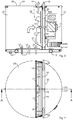
Figure 1 shows a motor-driven chimney draft system according to the invention seen from above; -
Figure 2 is a vertical section through the chimney draft system infigure 1 taken along the line A-A; -
Figure 3 corresponds tofigure 1 ; -
Figure 4 is a vertical section through the chimney draft system infigure 3 taken along the line B-B; and -
Figure 5 is a perspective view of the chimney draft system infigures 1-4 . - The figures show a motor-driven chimney draft system for mounting on top of a chimney leading flue gases from a fireplace such as a stove. In the shown embodiment the system has a generally cylindrical shape.
- In
figures 2 and4 are shown afitting device 10 at the bottom of the system which is used for fitting the system to the top of a chimney so that aflue gas inlet 11 of the system can receive aflow 12 of flue gases from the chimney. The flow of flue gases have a flow direction indicated by arrows which is the same flow direction as in in the chimney. A motor compartment 14 of the system houses amotor 13 which has amotor shaft 15 carrying animpeller 16 withimpeller blades 17, in this embodiment siximpeller blades 17, for driving the received flow of flue gases out through aflue gas outlet 18 at the top of the system. As shown, the motor compartment 14 is situated laterally relative to the flow direction of flue gases and is separated from the flow of flue gases by two separatingwalls motor shaft 15 extends through theseparating walls impeller 16 is driven by themotor 13 theimpeller blades 17 will expel the flue gases in radial directions relative to the impeller in a radial direction of the impeller, and flue gases will be sucked by theimpeller 16 in its axial direction as indicated by a curved arrow. - A
screen 21 is mounted on the separatingwall 19 on the upstream side of the impeller (here: below the impeller) and extends from theseparating wall 19 on the upstream side of theimpeller 16 and has a portion which extends in the downstream direction (here: upward) on the suction side of theimpeller 16 and covers a peripheral portion of some of theimpeller blades 17 and leaves a central suction zone uncovered. - When the
impeller 16 is driven in rotation by themotor 13 theimpeller blades 17 will drive flue gases in all radial directions away from theshaft 15, and a central zone will act as a suction zone and suck flue gases in theflue gas compartment 27 towards the suction zone. Thescreen 21 blocks a radial flow path from theimpeller 16 in the upstream direction (here: downward) towards theflue gas inlet 11, and thescreen 21 thereby prevents flue gases and air from being blown out through theflue gas inlet 11, i.e. in the undesired reverse direction. Flue gases which are sucked toward the central suction zone will consequently be blown in the downstream direction (here: upward) and out through theflue gas outlet 18 as indicated by an arrow at theflue gas outlet 18. - The
impeller 16 will also cause a vortex with a rotational movement of the flue gases in the direction of rotation of the impeller. The screen can therefore advantageously be asymmetric and have a unilateral portion extending in the downstream direction as indicated by a dashed line 21'. The portion of flue gases between theseparating wall 19 of theflue gas compartment 27 and the lateral portion 21' of thescreen 21 are moving in the desired downstream direction, and the lateral portion 21' of thescreen 21 separates this downstream flowing portion of the flue gases from the flue gases in the remaining part of the flue gas compartment whereby mixing is prevented or at least reduced with the effect that the efficiency of the system is further increased. - In a typical situation of use the
flue gas outlet 18 faces upward and in order to prevent rain entering the system through theflue gas outlet 18 from reaching the chimney through theflue gas inlet 11 anoptional rain screen 22 shown in dashed line can be arranged at the top wall of the system and extending downward into theflue gas compartment 27. If present, the lower edge of therain screen 22 will preferably be closer to the separatingwall 19 than is the upper edge of thescreen 21, so that water dripping from therain screen 22 will be caught by thescreen 21 and can be drained from the system as indicated byarrows 23 infigure 4 . The size and shape of therain screen 22 shown infigures 2 and4 are only for illustrative purposes. - Since the flue gas inlet 11 and the flue gas
flue gas outlet 18 are substantially aligned with no or negligible changes in direction or sharp edges that would increase the flow path resistance. Therefore, when themotor 13 is inactive the system will have only negligible influence on the flow. - The
top wall 28 of theflue gas compartment 27 is hinged and can be opened to give access to for inspection and easy cleaning by a chimney sweep. - The motor compartment 14 is separated from the
flue gas compartment 27 by avertical air space 24 defined by the separatingwalls air space 24 is closed downwardly whereby flue gases cannot enter into theair space 24, and theair space 24 has openings to the ambient at the two opposite vertical sides or, preferably, also upwardly i.e. at all three of the other sides allowing ambient air to flow through theair space 24. - Flue gases in the
flue gas compartment 27 will heat the separatingwall 19 and air in theair space 24 which is in contact with the separatingwall 19 will be heated, which will cause thermally induced convection whereby ambient air will be drawn into theair space 24 from the sides as indicated byarrows 25 infigures 1 and3 and leave theair space 24 in an upward direction as indicated byarrow 26 infigure 2 . In the shown typical situation of use theair space 24 is oriented vertically which enhances thermally induced convection. - The distance between the separating
walls flue gas compartment 27 to the motor compartment 14, and the thermally induced convection will have a cooling effect. Furthermore, wind will have access to theair space 24 and provide cooling. Finally, because theflue gas outlet 18 and the upper opening of theair space 24 are close to each other over almost the entire diameter of the system, the flue gas flow out of theflue gas outlet 18 will also draw air out through the upper opening of theair space 24. If desired, the motor shaft can carry an impeller in theair space 24 for assisting the thermally induced convection.
Claims (8)
- A motor-driven chimney draft system comprising:a flue gas inlet (11) for receiving a flow of flue gases,a flue gas outlet (18) for discharging the flow of flue gases,a flue gas compartment (27) in fluid communication with the flue gas inlet (11) and with the flue gas outlet (18), the flow of flue gases in the flue gas compartment (27) having a flow direction from the flue gas inlet (11) to the flue gas outlet (18),a motor compartment (14) housing a motor (13) having a motor shaft (15) extending through a separating wall (19) of the flue gas compartment (27), the motor shaft (15) carrying an impeller (16) for driving the received flow of flue gases in the flow direction,wherein the separating wall (19) of the flue gas compartment (27) and a separating wall (20) of the motor compartment (14), each separating wall (19, 20) extending parallel to the flow direction of flue gases, are arranged facing each other so as to define an air space (24) therebetween, the air space (24) having openings allowing ambient air to flow through the air space (24), characterized in that
the air space (24), defined by the separating walls (19, 20) which are at a distance from each other, is oriented vertically, and the air space (24) is closed downwardly and has openings to the ambient air at two opposite vertical sides and upwardly, allowing ambient air to flow through the air space (24) due to thermally induced natural convection. - A motor-driven chimney draft system according to claim 1 wherein the motor shaft (15) extends through both separating walls (19, 20).
- A motor-driven chimney draft system according to any one of the preceding claims wherein the motor compartment (14) is situated laterally relative to the flow direction and separated from the flow of flue gases by the separating wall (19), the motor shaft (15) extending in a direction transverse to the flow direction.
- A motor-driven chimney draft system system according to any one of the preceding claims wherein
the impeller drives the flue gases in radial directions of the impeller, and
a screen (21) is arranged on the separating wall (19) of the flue gas compartment (27), the screen (21) extending from the separating wall (19) of the flue gas compartment (27) upstream of the impeller (16) and having a portion which on a side of the impeller (16) opposite the separating wall (19) of the flue gas compartment (27) extends in the downstream direction and covers a peripheral portion of impeller blades (17) upstream of the motor shaft (15). - A motor-driven chimney draft system system according to claim 4 wherein a central suction zone of the impeller (16) is uncovered by the screen (21).
- A motor-driven chimney draft system according to any one of the preceding claims wherein the flue gas compartment (27) has a cover (28) which can be opened to allow access to the flue gas compartment (27).
- A motor-driven chimney draft system according to claim 4 or any of claims 5 to 6 when dependent on claim 4, wherein a rain screen (22) is arranged at a top wall (28) of the flue gas compartment (27) and extends downward into the flue gas compartment (27), the rain screen (22) having a lower edge which is closer to the separating wall (19) than is the upper edge of the screen (21).
- A motor-driven chimney draft system according to claim 4 or any of claims 5 to 7 when dependent on claim 4, wherein the screen (21) has a portion (21') extending in the downstream direction unilaterally relative to the central suction zone of the impeller (16).
Priority Applications (3)
| Application Number | Priority Date | Filing Date | Title |
|---|---|---|---|
| EP14200538.8A EP3040613B1 (en) | 2014-12-30 | 2014-12-30 | A motor-driven chimney draft system |
| DK14200538T DK3040613T3 (en) | 2014-12-30 | 2014-12-30 | Motor-driven chimney draft system |
| US14/981,556 US10113743B2 (en) | 2014-12-30 | 2015-12-28 | Motor-driven chimney draft system |
Applications Claiming Priority (1)
| Application Number | Priority Date | Filing Date | Title |
|---|---|---|---|
| EP14200538.8A EP3040613B1 (en) | 2014-12-30 | 2014-12-30 | A motor-driven chimney draft system |
Publications (2)
| Publication Number | Publication Date |
|---|---|
| EP3040613A1 EP3040613A1 (en) | 2016-07-06 |
| EP3040613B1 true EP3040613B1 (en) | 2019-08-07 |
Family
ID=52278468
Family Applications (1)
| Application Number | Title | Priority Date | Filing Date |
|---|---|---|---|
| EP14200538.8A Active EP3040613B1 (en) | 2014-12-30 | 2014-12-30 | A motor-driven chimney draft system |
Country Status (3)
| Country | Link |
|---|---|
| US (1) | US10113743B2 (en) |
| EP (1) | EP3040613B1 (en) |
| DK (1) | DK3040613T3 (en) |
Citations (4)
| Publication number | Priority date | Publication date | Assignee | Title |
|---|---|---|---|---|
| DE2607712A1 (en) * | 1976-02-25 | 1977-09-08 | Hans Schwarz Ohg | Fireplace waste air mixing hood - has internal shallow funnel within truncated conical hood for mixing |
| JPS63194119A (en) * | 1987-02-04 | 1988-08-11 | Matsushita Electric Ind Co Ltd | combustor exhaust system |
| DE4001849A1 (en) * | 1990-01-12 | 1991-07-18 | Langner Horst | Chimney fitted with extension and fan - incorporates collar to reduce noise emitted by fan unit |
| US5439349A (en) * | 1994-11-15 | 1995-08-08 | Kupferberg; Minel | Exhaust fan apparatus |
Family Cites Families (8)
| Publication number | Priority date | Publication date | Assignee | Title |
|---|---|---|---|---|
| US3782303A (en) * | 1972-07-06 | 1974-01-01 | Conco Inc | Draft inducer |
| US5070772A (en) * | 1990-03-15 | 1991-12-10 | Heico, Inc. | Venter |
| JP3097391B2 (en) | 1993-06-04 | 2000-10-10 | 松下電器産業株式会社 | Exhaust device |
| DE19755617B4 (en) | 1997-12-13 | 2014-02-27 | TROX TLT GmbH | flow channel |
| US20120083194A1 (en) * | 2003-03-06 | 2012-04-05 | Enervex, Inc. | Mechanical draft systems |
| US7018287B2 (en) | 2004-07-22 | 2006-03-28 | Minel Kupferberg | High velocity and high dilution exhaust system |
| CN2871928Y (en) * | 2006-03-03 | 2007-02-21 | 王键梅 | Civil centrifugal induced draft fan |
| DK2594847T3 (en) * | 2011-11-18 | 2018-06-25 | Exodraft As | A chimney-driven motor system and an impeller for use in the system |
-
2014
- 2014-12-30 EP EP14200538.8A patent/EP3040613B1/en active Active
- 2014-12-30 DK DK14200538T patent/DK3040613T3/en active
-
2015
- 2015-12-28 US US14/981,556 patent/US10113743B2/en active Active
Patent Citations (4)
| Publication number | Priority date | Publication date | Assignee | Title |
|---|---|---|---|---|
| DE2607712A1 (en) * | 1976-02-25 | 1977-09-08 | Hans Schwarz Ohg | Fireplace waste air mixing hood - has internal shallow funnel within truncated conical hood for mixing |
| JPS63194119A (en) * | 1987-02-04 | 1988-08-11 | Matsushita Electric Ind Co Ltd | combustor exhaust system |
| DE4001849A1 (en) * | 1990-01-12 | 1991-07-18 | Langner Horst | Chimney fitted with extension and fan - incorporates collar to reduce noise emitted by fan unit |
| US5439349A (en) * | 1994-11-15 | 1995-08-08 | Kupferberg; Minel | Exhaust fan apparatus |
Also Published As
| Publication number | Publication date |
|---|---|
| EP3040613A1 (en) | 2016-07-06 |
| US10113743B2 (en) | 2018-10-30 |
| US20160186993A1 (en) | 2016-06-30 |
| DK3040613T3 (en) | 2019-11-11 |
Similar Documents
| Publication | Publication Date | Title |
|---|---|---|
| US9279592B2 (en) | Evaporative cooler | |
| EP3550212B1 (en) | Cookware and exhaust device | |
| EP2918936B1 (en) | Air conditioner | |
| RU2012121941A (en) | CENTRIFUGAL CEILING FAN | |
| JP6311427B2 (en) | Air conditioner | |
| CN204987408U (en) | Drainage structure of air conditioner | |
| JP2017053514A (en) | Air conditioner | |
| US6450874B2 (en) | Thermostatically controlled power draft motor cooling system | |
| EP3901533A1 (en) | Compact forced ventilation system | |
| NO151382B (en) | VENTILATOR | |
| EP3040614B1 (en) | A motor-driven chimney draft system | |
| US10113743B2 (en) | Motor-driven chimney draft system | |
| CN104296214A (en) | Wind screen machine capable of facilitating removal of oily fume of ceiling type range hood | |
| CN101592158A (en) | Improved cooling airflow electric motor driving pump | |
| CN105757755B (en) | Top-suction type fume exhauster | |
| US9599339B2 (en) | Motor-driven chimney draft system and an impeller for use in the system | |
| CN215502532U (en) | Steam condensation structure and steam ager | |
| JP5908736B2 (en) | Drainage structure in indoor unit of air conditioner | |
| KR102111328B1 (en) | Ventilating apparatus | |
| CN105465018A (en) | High-temperature-resistant draught fan | |
| EP4375581A2 (en) | Cookware and exhaust device | |
| CN104791869A (en) | Near-suction type oil fume suction machine and top-suction type oil fume suction machine | |
| KR102256842B1 (en) | Impeller Structure of Exhaust System | |
| CN203349381U (en) | Built-in air conditioner | |
| CN203257699U (en) | Double-duct draught fan |
Legal Events
| Date | Code | Title | Description |
|---|---|---|---|
| PUAI | Public reference made under article 153(3) epc to a published international application that has entered the european phase |
Free format text: ORIGINAL CODE: 0009012 |
|
| AK | Designated contracting states |
Kind code of ref document: A1 Designated state(s): AL AT BE BG CH CY CZ DE DK EE ES FI FR GB GR HR HU IE IS IT LI LT LU LV MC MK MT NL NO PL PT RO RS SE SI SK SM TR |
|
| AX | Request for extension of the european patent |
Extension state: BA ME |
|
| STAA | Information on the status of an ep patent application or granted ep patent |
Free format text: STATUS: REQUEST FOR EXAMINATION WAS MADE |
|
| 17P | Request for examination filed |
Effective date: 20161222 |
|
| RBV | Designated contracting states (corrected) |
Designated state(s): AL AT BE BG CH CY CZ DE DK EE ES FI FR GB GR HR HU IE IS IT LI LT LU LV MC MK MT NL NO PL PT RO RS SE SI SK SM TR |
|
| STAA | Information on the status of an ep patent application or granted ep patent |
Free format text: STATUS: EXAMINATION IS IN PROGRESS |
|
| 17Q | First examination report despatched |
Effective date: 20180425 |
|
| GRAP | Despatch of communication of intention to grant a patent |
Free format text: ORIGINAL CODE: EPIDOSNIGR1 |
|
| STAA | Information on the status of an ep patent application or granted ep patent |
Free format text: STATUS: GRANT OF PATENT IS INTENDED |
|
| INTG | Intention to grant announced |
Effective date: 20190114 |
|
| GRAS | Grant fee paid |
Free format text: ORIGINAL CODE: EPIDOSNIGR3 |
|
| GRAJ | Information related to disapproval of communication of intention to grant by the applicant or resumption of examination proceedings by the epo deleted |
Free format text: ORIGINAL CODE: EPIDOSDIGR1 |
|
| GRAL | Information related to payment of fee for publishing/printing deleted |
Free format text: ORIGINAL CODE: EPIDOSDIGR3 |
|
| STAA | Information on the status of an ep patent application or granted ep patent |
Free format text: STATUS: EXAMINATION IS IN PROGRESS |
|
| GRAR | Information related to intention to grant a patent recorded |
Free format text: ORIGINAL CODE: EPIDOSNIGR71 |
|
| STAA | Information on the status of an ep patent application or granted ep patent |
Free format text: STATUS: GRANT OF PATENT IS INTENDED |
|
| INTC | Intention to grant announced (deleted) | ||
| GRAA | (expected) grant |
Free format text: ORIGINAL CODE: 0009210 |
|
| STAA | Information on the status of an ep patent application or granted ep patent |
Free format text: STATUS: THE PATENT HAS BEEN GRANTED |
|
| AK | Designated contracting states |
Kind code of ref document: B1 Designated state(s): AL AT BE BG CH CY CZ DE DK EE ES FI FR GB GR HR HU IE IS IT LI LT LU LV MC MK MT NL NO PL PT RO RS SE SI SK SM TR |
|
| INTG | Intention to grant announced |
Effective date: 20190628 |
|
| REG | Reference to a national code |
Ref country code: GB Ref legal event code: FG4D |
|
| REG | Reference to a national code |
Ref country code: CH Ref legal event code: EP Ref country code: AT Ref legal event code: REF Ref document number: 1164451 Country of ref document: AT Kind code of ref document: T Effective date: 20190815 |
|
| REG | Reference to a national code |
Ref country code: DE Ref legal event code: R096 Ref document number: 602014051208 Country of ref document: DE |
|
| REG | Reference to a national code |
Ref country code: IE Ref legal event code: FG4D |
|
| REG | Reference to a national code |
Ref country code: NL Ref legal event code: FP |
|
| REG | Reference to a national code |
Ref country code: DK Ref legal event code: T3 Effective date: 20191107 |
|
| REG | Reference to a national code |
Ref country code: SE Ref legal event code: TRGR |
|
| REG | Reference to a national code |
Ref country code: NO Ref legal event code: T2 Effective date: 20190807 |
|
| REG | Reference to a national code |
Ref country code: LT Ref legal event code: MG4D |
|
| PG25 | Lapsed in a contracting state [announced via postgrant information from national office to epo] |
Ref country code: BG Free format text: LAPSE BECAUSE OF FAILURE TO SUBMIT A TRANSLATION OF THE DESCRIPTION OR TO PAY THE FEE WITHIN THE PRESCRIBED TIME-LIMIT Effective date: 20191107 Ref country code: FI Free format text: LAPSE BECAUSE OF FAILURE TO SUBMIT A TRANSLATION OF THE DESCRIPTION OR TO PAY THE FEE WITHIN THE PRESCRIBED TIME-LIMIT Effective date: 20190807 Ref country code: LT Free format text: LAPSE BECAUSE OF FAILURE TO SUBMIT A TRANSLATION OF THE DESCRIPTION OR TO PAY THE FEE WITHIN THE PRESCRIBED TIME-LIMIT Effective date: 20190807 Ref country code: HR Free format text: LAPSE BECAUSE OF FAILURE TO SUBMIT A TRANSLATION OF THE DESCRIPTION OR TO PAY THE FEE WITHIN THE PRESCRIBED TIME-LIMIT Effective date: 20190807 Ref country code: PT Free format text: LAPSE BECAUSE OF FAILURE TO SUBMIT A TRANSLATION OF THE DESCRIPTION OR TO PAY THE FEE WITHIN THE PRESCRIBED TIME-LIMIT Effective date: 20191209 |
|
| REG | Reference to a national code |
Ref country code: AT Ref legal event code: MK05 Ref document number: 1164451 Country of ref document: AT Kind code of ref document: T Effective date: 20190807 |
|
| PG25 | Lapsed in a contracting state [announced via postgrant information from national office to epo] |
Ref country code: GR Free format text: LAPSE BECAUSE OF FAILURE TO SUBMIT A TRANSLATION OF THE DESCRIPTION OR TO PAY THE FEE WITHIN THE PRESCRIBED TIME-LIMIT Effective date: 20191108 Ref country code: ES Free format text: LAPSE BECAUSE OF FAILURE TO SUBMIT A TRANSLATION OF THE DESCRIPTION OR TO PAY THE FEE WITHIN THE PRESCRIBED TIME-LIMIT Effective date: 20190807 Ref country code: IS Free format text: LAPSE BECAUSE OF FAILURE TO SUBMIT A TRANSLATION OF THE DESCRIPTION OR TO PAY THE FEE WITHIN THE PRESCRIBED TIME-LIMIT Effective date: 20191207 Ref country code: RS Free format text: LAPSE BECAUSE OF FAILURE TO SUBMIT A TRANSLATION OF THE DESCRIPTION OR TO PAY THE FEE WITHIN THE PRESCRIBED TIME-LIMIT Effective date: 20190807 Ref country code: AL Free format text: LAPSE BECAUSE OF FAILURE TO SUBMIT A TRANSLATION OF THE DESCRIPTION OR TO PAY THE FEE WITHIN THE PRESCRIBED TIME-LIMIT Effective date: 20190807 Ref country code: LV Free format text: LAPSE BECAUSE OF FAILURE TO SUBMIT A TRANSLATION OF THE DESCRIPTION OR TO PAY THE FEE WITHIN THE PRESCRIBED TIME-LIMIT Effective date: 20190807 |
|
| PG25 | Lapsed in a contracting state [announced via postgrant information from national office to epo] |
Ref country code: TR Free format text: LAPSE BECAUSE OF FAILURE TO SUBMIT A TRANSLATION OF THE DESCRIPTION OR TO PAY THE FEE WITHIN THE PRESCRIBED TIME-LIMIT Effective date: 20190807 |
|
| PG25 | Lapsed in a contracting state [announced via postgrant information from national office to epo] |
Ref country code: PL Free format text: LAPSE BECAUSE OF FAILURE TO SUBMIT A TRANSLATION OF THE DESCRIPTION OR TO PAY THE FEE WITHIN THE PRESCRIBED TIME-LIMIT Effective date: 20190807 Ref country code: AT Free format text: LAPSE BECAUSE OF FAILURE TO SUBMIT A TRANSLATION OF THE DESCRIPTION OR TO PAY THE FEE WITHIN THE PRESCRIBED TIME-LIMIT Effective date: 20190807 Ref country code: RO Free format text: LAPSE BECAUSE OF FAILURE TO SUBMIT A TRANSLATION OF THE DESCRIPTION OR TO PAY THE FEE WITHIN THE PRESCRIBED TIME-LIMIT Effective date: 20190807 Ref country code: IT Free format text: LAPSE BECAUSE OF FAILURE TO SUBMIT A TRANSLATION OF THE DESCRIPTION OR TO PAY THE FEE WITHIN THE PRESCRIBED TIME-LIMIT Effective date: 20190807 Ref country code: EE Free format text: LAPSE BECAUSE OF FAILURE TO SUBMIT A TRANSLATION OF THE DESCRIPTION OR TO PAY THE FEE WITHIN THE PRESCRIBED TIME-LIMIT Effective date: 20190807 |
|
| PGFP | Annual fee paid to national office [announced via postgrant information from national office to epo] |
Ref country code: IE Payment date: 20200309 Year of fee payment: 6 |
|
| PG25 | Lapsed in a contracting state [announced via postgrant information from national office to epo] |
Ref country code: IS Free format text: LAPSE BECAUSE OF FAILURE TO SUBMIT A TRANSLATION OF THE DESCRIPTION OR TO PAY THE FEE WITHIN THE PRESCRIBED TIME-LIMIT Effective date: 20200224 Ref country code: SM Free format text: LAPSE BECAUSE OF FAILURE TO SUBMIT A TRANSLATION OF THE DESCRIPTION OR TO PAY THE FEE WITHIN THE PRESCRIBED TIME-LIMIT Effective date: 20190807 Ref country code: CZ Free format text: LAPSE BECAUSE OF FAILURE TO SUBMIT A TRANSLATION OF THE DESCRIPTION OR TO PAY THE FEE WITHIN THE PRESCRIBED TIME-LIMIT Effective date: 20190807 Ref country code: SK Free format text: LAPSE BECAUSE OF FAILURE TO SUBMIT A TRANSLATION OF THE DESCRIPTION OR TO PAY THE FEE WITHIN THE PRESCRIBED TIME-LIMIT Effective date: 20190807 |
|
| REG | Reference to a national code |
Ref country code: DE Ref legal event code: R097 Ref document number: 602014051208 Country of ref document: DE |
|
| PLBE | No opposition filed within time limit |
Free format text: ORIGINAL CODE: 0009261 |
|
| STAA | Information on the status of an ep patent application or granted ep patent |
Free format text: STATUS: NO OPPOSITION FILED WITHIN TIME LIMIT |
|
| PG2D | Information on lapse in contracting state deleted |
Ref country code: IS |
|
| REG | Reference to a national code |
Ref country code: CH Ref legal event code: PL |
|
| 26N | No opposition filed |
Effective date: 20200603 |
|
| PG25 | Lapsed in a contracting state [announced via postgrant information from national office to epo] |
Ref country code: MC Free format text: LAPSE BECAUSE OF FAILURE TO SUBMIT A TRANSLATION OF THE DESCRIPTION OR TO PAY THE FEE WITHIN THE PRESCRIBED TIME-LIMIT Effective date: 20190807 Ref country code: SI Free format text: LAPSE BECAUSE OF FAILURE TO SUBMIT A TRANSLATION OF THE DESCRIPTION OR TO PAY THE FEE WITHIN THE PRESCRIBED TIME-LIMIT Effective date: 20190807 |
|
| PG25 | Lapsed in a contracting state [announced via postgrant information from national office to epo] |
Ref country code: LU Free format text: LAPSE BECAUSE OF NON-PAYMENT OF DUE FEES Effective date: 20191230 |
|
| PG25 | Lapsed in a contracting state [announced via postgrant information from national office to epo] |
Ref country code: LI Free format text: LAPSE BECAUSE OF NON-PAYMENT OF DUE FEES Effective date: 20191231 Ref country code: CH Free format text: LAPSE BECAUSE OF NON-PAYMENT OF DUE FEES Effective date: 20191231 |
|
| PG25 | Lapsed in a contracting state [announced via postgrant information from national office to epo] |
Ref country code: CY Free format text: LAPSE BECAUSE OF FAILURE TO SUBMIT A TRANSLATION OF THE DESCRIPTION OR TO PAY THE FEE WITHIN THE PRESCRIBED TIME-LIMIT Effective date: 20190807 |
|
| PG25 | Lapsed in a contracting state [announced via postgrant information from national office to epo] |
Ref country code: MT Free format text: LAPSE BECAUSE OF FAILURE TO SUBMIT A TRANSLATION OF THE DESCRIPTION OR TO PAY THE FEE WITHIN THE PRESCRIBED TIME-LIMIT Effective date: 20190807 Ref country code: HU Free format text: LAPSE BECAUSE OF FAILURE TO SUBMIT A TRANSLATION OF THE DESCRIPTION OR TO PAY THE FEE WITHIN THE PRESCRIBED TIME-LIMIT; INVALID AB INITIO Effective date: 20141230 |
|
| PG25 | Lapsed in a contracting state [announced via postgrant information from national office to epo] |
Ref country code: IE Free format text: LAPSE BECAUSE OF NON-PAYMENT OF DUE FEES Effective date: 20201230 |
|
| PG25 | Lapsed in a contracting state [announced via postgrant information from national office to epo] |
Ref country code: MK Free format text: LAPSE BECAUSE OF FAILURE TO SUBMIT A TRANSLATION OF THE DESCRIPTION OR TO PAY THE FEE WITHIN THE PRESCRIBED TIME-LIMIT Effective date: 20190807 |
|
| P01 | Opt-out of the competence of the unified patent court (upc) registered |
Effective date: 20230523 |
|
| PGFP | Annual fee paid to national office [announced via postgrant information from national office to epo] |
Ref country code: DE Payment date: 20251211 Year of fee payment: 12 |
|
| PGFP | Annual fee paid to national office [announced via postgrant information from national office to epo] |
Ref country code: GB Payment date: 20251219 Year of fee payment: 12 |
|
| PGFP | Annual fee paid to national office [announced via postgrant information from national office to epo] |
Ref country code: DK Payment date: 20251224 Year of fee payment: 12 |
|
| PGFP | Annual fee paid to national office [announced via postgrant information from national office to epo] |
Ref country code: NL Payment date: 20251219 Year of fee payment: 12 Ref country code: FR Payment date: 20251223 Year of fee payment: 12 |
|
| PGFP | Annual fee paid to national office [announced via postgrant information from national office to epo] |
Ref country code: BE Payment date: 20251219 Year of fee payment: 12 |
|
| PGFP | Annual fee paid to national office [announced via postgrant information from national office to epo] |
Ref country code: SE Payment date: 20251219 Year of fee payment: 12 |
|
| PGFP | Annual fee paid to national office [announced via postgrant information from national office to epo] |
Ref country code: NO Payment date: 20251230 Year of fee payment: 12 |