EP3040562A1 - Regulator structure and centrifugal compressor - Google Patents
Regulator structure and centrifugal compressor Download PDFInfo
- Publication number
- EP3040562A1 EP3040562A1 EP14840668.9A EP14840668A EP3040562A1 EP 3040562 A1 EP3040562 A1 EP 3040562A1 EP 14840668 A EP14840668 A EP 14840668A EP 3040562 A1 EP3040562 A1 EP 3040562A1
- Authority
- EP
- European Patent Office
- Prior art keywords
- regulator
- driven gear
- rectangle
- shaped
- rotate
- Prior art date
- Legal status (The legal status is an assumption and is not a legal conclusion. Google has not performed a legal analysis and makes no representation as to the accuracy of the status listed.)
- Granted
Links
Images


Classifications
-
- F—MECHANICAL ENGINEERING; LIGHTING; HEATING; WEAPONS; BLASTING
- F04—POSITIVE - DISPLACEMENT MACHINES FOR LIQUIDS; PUMPS FOR LIQUIDS OR ELASTIC FLUIDS
- F04D—NON-POSITIVE-DISPLACEMENT PUMPS
- F04D27/00—Control, e.g. regulation, of pumps, pumping installations or pumping systems specially adapted for elastic fluids
- F04D27/002—Control, e.g. regulation, of pumps, pumping installations or pumping systems specially adapted for elastic fluids by varying geometry within the pumps, e.g. by adjusting vanes
-
- F—MECHANICAL ENGINEERING; LIGHTING; HEATING; WEAPONS; BLASTING
- F04—POSITIVE - DISPLACEMENT MACHINES FOR LIQUIDS; PUMPS FOR LIQUIDS OR ELASTIC FLUIDS
- F04D—NON-POSITIVE-DISPLACEMENT PUMPS
- F04D17/00—Radial-flow pumps, e.g. centrifugal pumps; Helico-centrifugal pumps
- F04D17/08—Centrifugal pumps
- F04D17/10—Centrifugal pumps for compressing or evacuating
-
- F—MECHANICAL ENGINEERING; LIGHTING; HEATING; WEAPONS; BLASTING
- F04—POSITIVE - DISPLACEMENT MACHINES FOR LIQUIDS; PUMPS FOR LIQUIDS OR ELASTIC FLUIDS
- F04D—NON-POSITIVE-DISPLACEMENT PUMPS
- F04D27/00—Control, e.g. regulation, of pumps, pumping installations or pumping systems specially adapted for elastic fluids
- F04D27/02—Surge control
-
- F—MECHANICAL ENGINEERING; LIGHTING; HEATING; WEAPONS; BLASTING
- F04—POSITIVE - DISPLACEMENT MACHINES FOR LIQUIDS; PUMPS FOR LIQUIDS OR ELASTIC FLUIDS
- F04D—NON-POSITIVE-DISPLACEMENT PUMPS
- F04D27/00—Control, e.g. regulation, of pumps, pumping installations or pumping systems specially adapted for elastic fluids
- F04D27/02—Surge control
- F04D27/0253—Surge control by throttling
-
- F—MECHANICAL ENGINEERING; LIGHTING; HEATING; WEAPONS; BLASTING
- F04—POSITIVE - DISPLACEMENT MACHINES FOR LIQUIDS; PUMPS FOR LIQUIDS OR ELASTIC FLUIDS
- F04D—NON-POSITIVE-DISPLACEMENT PUMPS
- F04D29/00—Details, component parts, or accessories
- F04D29/26—Rotors specially for elastic fluids
- F04D29/28—Rotors specially for elastic fluids for centrifugal or helico-centrifugal pumps for radial-flow or helico-centrifugal pumps
- F04D29/284—Rotors specially for elastic fluids for centrifugal or helico-centrifugal pumps for radial-flow or helico-centrifugal pumps for compressors
-
- F—MECHANICAL ENGINEERING; LIGHTING; HEATING; WEAPONS; BLASTING
- F04—POSITIVE - DISPLACEMENT MACHINES FOR LIQUIDS; PUMPS FOR LIQUIDS OR ELASTIC FLUIDS
- F04D—NON-POSITIVE-DISPLACEMENT PUMPS
- F04D29/00—Details, component parts, or accessories
- F04D29/40—Casings; Connections of working fluid
- F04D29/42—Casings; Connections of working fluid for radial or helico-centrifugal pumps
- F04D29/44—Fluid-guiding means, e.g. diffusers
- F04D29/441—Fluid-guiding means, e.g. diffusers especially adapted for elastic fluid pumps
- F04D29/444—Bladed diffusers
-
- F—MECHANICAL ENGINEERING; LIGHTING; HEATING; WEAPONS; BLASTING
- F04—POSITIVE - DISPLACEMENT MACHINES FOR LIQUIDS; PUMPS FOR LIQUIDS OR ELASTIC FLUIDS
- F04D—NON-POSITIVE-DISPLACEMENT PUMPS
- F04D29/00—Details, component parts, or accessories
- F04D29/40—Casings; Connections of working fluid
- F04D29/42—Casings; Connections of working fluid for radial or helico-centrifugal pumps
- F04D29/44—Fluid-guiding means, e.g. diffusers
- F04D29/46—Fluid-guiding means, e.g. diffusers adjustable
- F04D29/462—Fluid-guiding means, e.g. diffusers adjustable especially adapted for elastic fluid pumps
-
- F—MECHANICAL ENGINEERING; LIGHTING; HEATING; WEAPONS; BLASTING
- F04—POSITIVE - DISPLACEMENT MACHINES FOR LIQUIDS; PUMPS FOR LIQUIDS OR ELASTIC FLUIDS
- F04D—NON-POSITIVE-DISPLACEMENT PUMPS
- F04D29/00—Details, component parts, or accessories
- F04D29/40—Casings; Connections of working fluid
- F04D29/42—Casings; Connections of working fluid for radial or helico-centrifugal pumps
- F04D29/44—Fluid-guiding means, e.g. diffusers
- F04D29/46—Fluid-guiding means, e.g. diffusers adjustable
- F04D29/462—Fluid-guiding means, e.g. diffusers adjustable especially adapted for elastic fluid pumps
- F04D29/464—Fluid-guiding means, e.g. diffusers adjustable especially adapted for elastic fluid pumps adjusting flow cross-section, otherwise than by using adjustable stator blades
-
- F—MECHANICAL ENGINEERING; LIGHTING; HEATING; WEAPONS; BLASTING
- F05—INDEXING SCHEMES RELATING TO ENGINES OR PUMPS IN VARIOUS SUBCLASSES OF CLASSES F01-F04
- F05D—INDEXING SCHEME FOR ASPECTS RELATING TO NON-POSITIVE-DISPLACEMENT MACHINES OR ENGINES, GAS-TURBINES OR JET-PROPULSION PLANTS
- F05D2250/00—Geometry
- F05D2250/50—Inlet or outlet
- F05D2250/52—Outlet
-
- F—MECHANICAL ENGINEERING; LIGHTING; HEATING; WEAPONS; BLASTING
- F25—REFRIGERATION OR COOLING; COMBINED HEATING AND REFRIGERATION SYSTEMS; HEAT PUMP SYSTEMS; MANUFACTURE OR STORAGE OF ICE; LIQUEFACTION SOLIDIFICATION OF GASES
- F25B—REFRIGERATION MACHINES, PLANTS OR SYSTEMS; COMBINED HEATING AND REFRIGERATION SYSTEMS; HEAT PUMP SYSTEMS
- F25B1/00—Compression machines, plants or systems with non-reversible cycle
- F25B1/04—Compression machines, plants or systems with non-reversible cycle with compressor of rotary type
- F25B1/053—Compression machines, plants or systems with non-reversible cycle with compressor of rotary type of turbine type
Definitions
- the present disclosure relates to a regulator assembly, more particularly, to a regulator assembly for regulating the outlet width of the impeller of a centrifugal compressor, and to a centrifugal compressor.
- the regulator is installed at the outlet of the impeller, forming a segment with an adjustable width.
- the outlet width of the impeller is regulated according to the operating conditions of the unit, so as to enable the unit to remain the highest operating efficiency in a wider range.
- the regulator of the centrifugal compressor is normally linked with the regulating mechanism of the impeller, the regulator is not independent in structure, and thus the control is not precise enough. What's more, the regulating range of the adjustable width of the impeller is relatively smaller, and the regulator of the centrifugal compressor is not applicable to compressors under various kinds of operating conditions.
- the present disclosure provides a regulator assembly, comprising a vaned diffuser, wherein, said regulator assembly further comprises a motor, a driving gear, a driven gear and a regulating mechanism; the motor is rotatable forwardly and reversibly; the driving gear is engaged with the driven gear; the regulating mechanism comprises a regulator, a supporting member and regulator sliding members; the driven gear is sleeved on the regulator; the regulator is sleeved on the supporting member; the driven gear has rectangle-shaped through holes thereon, the rectangle-shaped through holes are disposed and extend along an axis of the driven gear; the regulator sliding members are fixed to the regulator through the rectangle-shaped through holes; the vaned diffuser is fixed on the supporting member, and is provided with internal threads; the regulator is provided with external threads, the external threads are engageable with the internal threads of the vaned diffuser; the motor is configured to drive the driving gear to rotate; the driving gear is configured to drive the driven gear to rotate; the driven gear is configured to push the regulator sliding members
- a bearing is disposed between the driven gear and the driven gear stopper.
- grooves which match with the rectangle-shaped through holes, are disposed on a periphery of the regulator; an axis of each groove is perpendicular to the axis of the driven gear;
- Each regulator sliding member is fixed in corresponding groove through corresponding rectangle-shaped through hole.
- At least two rectangle-shaped through holes are arranged evenly along a circumference of the driven gear; the number of the grooves is identical to the number of the rectangle-shaped through holes.
- the groove is provided with internal threads; the regulator sliding member is a bolt; the internal threads of the groove are engaged with and fixed with external threads of the regulator sliding member.
- a sealing groove is disposed in a periphery of the supporting member; a sealing ring is disposed in the sealing groove.
- length of the regulator is greater than length of the supporting member.
- a refrigeration compressor of the present disclosure comprises an impeller and the regulator assembly mentioned above.
- an end of the regulator with external threads thereon is arranged near an outlet of the impeller; when the motor drives the driving gear to rotate forwardly, the driving gear drives the driven gear to rotate forwardly, and the end of the regulator with external threads thereon is retracted continuously, till the outlet of the impeller is opened completely; when the motor drives the driving gear to rotate reversibly, the driving gear drives the driven gear to rotate reversibly, and the end of the regulator with external threads thereon extends continuously, till the outlet of the impeller is closed completely.
- the present disclosure has the beneficial effects as follows: the regulator assembly and the centrifugal compressor can realize a larger regulating range and have a wider range of applications; the outlet can be sealed completely, which prevents the refrigerant from flowing backwards to drive the impeller to rotate reversely, thereby avoiding the damage to the impeller; the regulator assembly is controlled independently, fewer transmission mechanisms are required, thus the transmission efficiency and the reliability are higher; the air flow direction and air flow rate at the inlet of the vaned diffuser are maintained unchanged, which reduces impact losses and avoids surges effectively; the overall structure of the regulator assembly is compact, and the regulator assembly is convenient to process and produce, and is convenient to refit.
- a regulator assembly is provided.
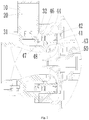
- Fig.1 is a schematic diagram illustrating the regulator assembly completely opened according to the first embodiment of the present invention.
- the regulator assembly comprises a motor 20, a driving gear 31, a driven gear 32, a vaned diffuser 42 and a regulating mechanism.
- the motor 20 is rotatable forwardly and reversibly.
- the driving gear 31 and the driven gear 32 are bevel gears.
- the driving gear 31 is connected with the motor 20, and the motor 20 drives the driving gear 31 to rotate. As the driving gear 31 is engaged with the driven gear 32, the driven gear 32 rotates synchronously.
- the regulating mechanism comprises a regulator 41, a supporting member 43 and regulator sliding members 47.
- the outer contour of the supporting member 43 is cylinder-shaped.
- the regulator 41 is formed through rotation machining, and has a through hole in the center.
- the regulator 41 is sleeved on the outer contour of the supporting member 43.
- the length of the regulator 41 is greater than the length of the supporting member 43.
- the supporting member 43 is disposed at the intermediate part of the regulator 41, so that the regulator 41 can be supported more evenly.
- the motor 20 drives the driving gear 31 to rotate, and the driving gear 31 drives the driven gear 32 to rotate.
- the driven gear 32 pushes the regulator sliding members 47 to move, and the regulator sliding members 47 drive the regulator 41 to rotate relative to the vaned diffuser 42, thus the regulator 41 moves along its axis.
- the driven gear 32 is sleeved on the regulator 41, the axis of the driven gear 32 is coincident with the axis of the regulator 41.
- the driven gear 32 has rectangle-shaped through holes thereon, and the axis of each rectangle-shaped through hole is perpendicular to the axis of the driven gear 32.
- the rectangle-shaped through hole extends along the axis of the driven gear 32. At least two rectangle-shaped through holes are arranged in the driven gear 32. In consideration of difficulties of processing and balance of forces acting on the driven gear, two rectangle-shaped through holes are provided preferably.
- the regulator sliding members 47 are fixed to the regulator 41 through the rectangle-shaped through holes, and the regulator sliding member is fixed with the regulator 41 through welding or is integrally formed with the regulator 41.
- grooves are provided at the proximal end of the regulator 41, which is proximal to the driven gear 32.
- the number of the grooves is identical to the number of the rectangle-shaped through holes, and the positions of the grooves arranged on the circumference of the regulator 41 correspond with the positions of the rectangle-shaped through holes.
- the regulator sliding member 47 is connected to the groove through the rectangle-shaped through hole in the driven gear 32. This kind of structure is easy to process and the installation is fixed and stable.
- the groove may be provided with threads, and the regulator sliding member 47 may be provided with threads as well, so that the regulator sliding member 47 is connected with the groove reliably through threads.
- the regulator sliding member 47 is a screw or a bolt.
- the regulator 41 and the regulator sliding member 47, as an integral assembly, move in the rectangle-shaped through hole in the axial direction of the regulator 41.
- the length of the rectangle-shaped through hole determines the displacement distance in the axial direction.
- the vaned diffuser 42 is provided with internal threads.
- the vaned diffuser 42 is sleeved on the external threads of the regulator 41, and is connected with the regulator 41 through threads. Meanwhile, the vaned diffuser 42 is fixed on the supporting member 43.
- the regulator 41 threadably engages with the vaned diffuser 42, and the vaned diffuser 42 is positioned and fixed, and thus the rotation of the regulator 41 will make itself to move in the axial direction, and the regulator 41 is pushed forwards along the axial direction through the internal threads of the vaned diffuser 42.
- the motor 20 rotates reversibly, the motor drives the driving gear 31, the driven gear 32 and the regulator 41 to rotate reversibly, and the regulator 41 moves backwards along the axial direction through the internal threads of the vaned diffuser 42.
- the length of the external threads of the regulator 41 is designed according to actual requirements, and the length of the corresponding rectangle-shaped through hole in the driven gear 32 is adjusted accordingly, thereby realizing a wider regulating rang and meeting different requirements under practical conditions.
- a driven gear stopper 44 is arranged on the regulator 41.
- the driven gear stopper 44 has a through hole in the center and is sleeved on the regulator 41.
- the regulating mechanism further comprises a position-limiting fastener 46, which fixes the driven gear stopper 44 on the case 10.
- the position-limiting fastener 46 may be a bolt, a positioning pin or a key in structure. Multiple position-limiting fasteners 46 may be arranged along the periphery of the driven gear stopper 44.
- a sealing groove is provided in a periphery of the supporting member 43 to contain a sealing ring 48, which ensures a good sealing between the regulator 41 and the supporting member 43.
- the regulator assembly is installed on the centrifugal compressor.
- the centrifugal compressor comprises a case 10.
- the supporting member 43 is fixed on the case 10.
- the end of the regulator 41 with external threads thereon is disposed near the outlet of the impeller 50.
- the axial movement of the regulator 41 causes the expansion and contraction of the regulator 41, thereby changing the outlet width of the impeller 50.
- Fig. 2 is a partial schematic diagram illustrating the regulator assembly incompletely opened according to the first embodiment of the present invention.
- the regulator 41 of the regulator assembly is in a state of being incompletely opened.
- the directions denoted by the double-headed arrow are the directions in which the regulator 41 moves along its axis; the direction denoted by the single-headed arrow is the direction in which the refrigerant in the centrifugal compressor flows.
- Fig. 3 is a partial schematic diagram illustrating the regulator assembly completely closed according to the first embodiment of the present invention.
- the motor 20 drives the driving gear 31 to rotate reversibly
- the driving gear 31 drives the driven gear 32 to rotate reversibly
- the end of the regulator 41 with external threads thereon extends continuously, till the outlet of the impeller 50 is closed completely.
- the outlet of the impeller 50 is sealed completely, which prevents the refrigerant from flowing backwards to drive the impeller 50 to rotate reversely.
- the regulator assembly does not need to use a check valve, thereby preventing the impeller 50 from rotating reversely to cause damages.
- Fig. 4 is a schematic diagram illustrating the regulator assembly completely opened according to the second embodiment of the present invention.
- the second embodiment differs from the first embodiment shown in Fig.1 in that: in the regulator assembly, a bearing 49 is provided between the driven gear 32 and the vaned diffuser 42.
- the bearing 49 is a thrust bearing.
- the frictional resistance of the thrust bearing is relative smaller and the operating state of the thrust bearing is better.
- the regulator assembly may be installed in the existing space of the conventional centrifugal compressor by slightly refitting the existing vaned diffuser and the existing case. By slightly changing the dimension of the regulator 41, the regulator 41 can be applied to impellers 50 with different diameters. The regulator assembly can be applied to centrifugal compressors with different powers, and has a wider range of applications.
- the present disclosure can regulate the outlet width of the impellers 50 precisely according to the operating conditions of applications, so as to form continuous and regulable width, enabling the centrifugal compressor to operate at the highest efficiency.
- the regulator assembly is controlled independently, fewer transmission mechanisms are required, and the transmission efficiency and the reliability are higher. Through regulating by the regulator assembly, it is ensured that the air flow direction and air flow rate at the inlet of the vaned diffuser 42 are maintained unchanged, which reduces impact losses and avoids surges effectively.
- the regulator assembly has high reliability, and the centrifugal compressor has a wider operating range.
- the overall structure of the regulator assembly is compact, and the regulator assembly is convenient to process and produce.
Landscapes
- Engineering & Computer Science (AREA)
- Mechanical Engineering (AREA)
- General Engineering & Computer Science (AREA)
- Physics & Mathematics (AREA)
- Geometry (AREA)
- Structures Of Non-Positive Displacement Pumps (AREA)
Abstract
Description
- This application claims the benefit of priority of Chinese Patent Application No.
201310377440.4, filed on August 26, 2013 - The present disclosure relates to a regulator assembly, more particularly, to a regulator assembly for regulating the outlet width of the impeller of a centrifugal compressor, and to a centrifugal compressor.
- In a centrifugal compressor of the prior art, the regulator is installed at the outlet of the impeller, forming a segment with an adjustable width. The outlet width of the impeller is regulated according to the operating conditions of the unit, so as to enable the unit to remain the highest operating efficiency in a wider range. In the prior art, the regulator of the centrifugal compressor is normally linked with the regulating mechanism of the impeller, the regulator is not independent in structure, and thus the control is not precise enough. What's more, the regulating range of the adjustable width of the impeller is relatively smaller, and the regulator of the centrifugal compressor is not applicable to compressors under various kinds of operating conditions.
- In view of the defects above, after long time of research and practice, the inventors finally obtained the present invention.
- In view of the situations, it is imperative to provide a regulator assembly capable of realizing a larger regulating range, and to provide a centrifugal compressor.
- The present disclosure provides a regulator assembly, comprising a vaned diffuser, wherein, said regulator assembly further comprises a motor, a driving gear, a driven gear and a regulating mechanism;
the motor is rotatable forwardly and reversibly; the driving gear is engaged with the driven gear;
the regulating mechanism comprises a regulator, a supporting member and regulator sliding members;
the driven gear is sleeved on the regulator; the regulator is sleeved on the supporting member;
the driven gear has rectangle-shaped through holes thereon, the rectangle-shaped through holes are disposed and extend along an axis of the driven gear;
the regulator sliding members are fixed to the regulator through the rectangle-shaped through holes;
the vaned diffuser is fixed on the supporting member, and is provided with internal threads;
the regulator is provided with external threads, the external threads are engageable with the internal threads of the vaned diffuser;
the motor is configured to drive the driving gear to rotate; the driving gear is configured to drive the driven gear to rotate; the driven gear is configured to push the regulator sliding members to move; and the regulator sliding members are configured to drive the regulator to rotate relative to the vaned diffuser, thus driving the regulator to move along its axis. In some embodiments, the regulator assembly further comprises a driven gear stopper;
the driven gear stopper is sleeved on the regulator, and is disposed between the driven gear and the vaned diffuser. - In some embodiments, a bearing is disposed between the driven gear and the driven gear stopper.
- In some embodiments, grooves, which match with the rectangle-shaped through holes, are disposed on a periphery of the regulator; an axis of each groove is perpendicular to the axis of the driven gear;
- Each regulator sliding member is fixed in corresponding groove through corresponding rectangle-shaped through hole.
- In some embodiments, at least two rectangle-shaped through holes are arranged evenly along a circumference of the driven gear;
the number of the grooves is identical to the number of the rectangle-shaped through holes. - In some embodiments, the groove is provided with internal threads;
the regulator sliding member is a bolt; the internal threads of the groove are engaged with and fixed with external threads of the regulator sliding member. - In some embodiments, a sealing groove is disposed in a periphery of the supporting member; a sealing ring is disposed in the sealing groove.
- In some embodiments, length of the regulator is greater than length of the supporting member.
- A refrigeration compressor of the present disclosure comprises an impeller and the regulator assembly mentioned above.
- In some embodiments, an end of the regulator with external threads thereon is arranged near an outlet of the impeller;
when the motor drives the driving gear to rotate forwardly, the driving gear drives the driven gear to rotate forwardly, and the end of the regulator with external threads thereon is retracted continuously, till the outlet of the impeller is opened completely; when the motor drives the driving gear to rotate reversibly, the driving gear drives the driven gear to rotate reversibly, and the end of the regulator with external threads thereon extends continuously, till the outlet of the impeller is closed completely. - As compared with the prior art, the present disclosure has the beneficial effects as follows: the regulator assembly and the centrifugal compressor can realize a larger regulating range and have a wider range of applications; the outlet can be sealed completely, which prevents the refrigerant from flowing backwards to drive the impeller to rotate reversely, thereby avoiding the damage to the impeller; the regulator assembly is controlled independently, fewer transmission mechanisms are required, thus the transmission efficiency and the reliability are higher; the air flow direction and air flow rate at the inlet of the vaned diffuser are maintained unchanged, which reduces impact losses and avoids surges effectively; the overall structure of the regulator assembly is compact, and the regulator assembly is convenient to process and produce, and is convenient to refit.
-
-
Fig. 1 is a schematic diagram illustrating the regulator assembly completely opened according to the first embodiment of the present invention; -
Fig. 2 is a partial schematic diagram illustrating the regulator assembly incompletely opened according to the first embodiment of the present invention; -
Fig. 3 is a partial schematic diagram illustrating the regulator assembly completely closed according to the first embodiment of the present invention; -
Fig. 4 is a schematic diagram illustrating the regulator assembly completely opened according to the second embodiment of the present invention. - In order to solve the problem of the too small regulating range, a regulator assembly is provided.
- The technical features above, additional technical features and the beneficial effects of the present invention will be described in more details with reference to the accompanying figures.
-
Fig.1 is a schematic diagram illustrating the regulator assembly completely opened according to the first embodiment of the present invention. As shown inFig.1 , the regulator assembly comprises amotor 20, adriving gear 31, a drivengear 32, avaned diffuser 42 and a regulating mechanism. - The
motor 20 is rotatable forwardly and reversibly. - Preferably, the
driving gear 31 and the drivengear 32 are bevel gears. - The
driving gear 31 is connected with themotor 20, and themotor 20 drives thedriving gear 31 to rotate. As thedriving gear 31 is engaged with the drivengear 32, the drivengear 32 rotates synchronously. - The regulating mechanism comprises a
regulator 41, a supportingmember 43 andregulator sliding members 47. - The outer contour of the supporting
member 43 is cylinder-shaped. - The
regulator 41 is formed through rotation machining, and has a through hole in the center. Theregulator 41 is sleeved on the outer contour of the supportingmember 43. The length of theregulator 41 is greater than the length of the supportingmember 43. The supportingmember 43 is disposed at the intermediate part of theregulator 41, so that theregulator 41 can be supported more evenly. - The
motor 20 drives thedriving gear 31 to rotate, and thedriving gear 31 drives the drivengear 32 to rotate. The drivengear 32 pushes theregulator sliding members 47 to move, and theregulator sliding members 47 drive theregulator 41 to rotate relative to thevaned diffuser 42, thus theregulator 41 moves along its axis. - The driven
gear 32 is sleeved on theregulator 41, the axis of the drivengear 32 is coincident with the axis of theregulator 41. The drivengear 32 has rectangle-shaped through holes thereon, and the axis of each rectangle-shaped through hole is perpendicular to the axis of the drivengear 32. The rectangle-shaped through hole extends along the axis of the drivengear 32. At least two rectangle-shaped through holes are arranged in the drivengear 32. In consideration of difficulties of processing and balance of forces acting on the driven gear, two rectangle-shaped through holes are provided preferably. - The
regulator sliding members 47 are fixed to theregulator 41 through the rectangle-shaped through holes, and the regulator sliding member is fixed with theregulator 41 through welding or is integrally formed with theregulator 41. - Preferably, grooves are provided at the proximal end of the
regulator 41, which is proximal to the drivengear 32. The number of the grooves is identical to the number of the rectangle-shaped through holes, and the positions of the grooves arranged on the circumference of theregulator 41 correspond with the positions of the rectangle-shaped through holes. Theregulator sliding member 47 is connected to the groove through the rectangle-shaped through hole in the drivengear 32. This kind of structure is easy to process and the installation is fixed and stable. - The groove may be provided with threads, and the
regulator sliding member 47 may be provided with threads as well, so that theregulator sliding member 47 is connected with the groove reliably through threads. Theregulator sliding member 47 is a screw or a bolt. Theregulator 41 and theregulator sliding member 47, as an integral assembly, move in the rectangle-shaped through hole in the axial direction of theregulator 41. The length of the rectangle-shaped through hole determines the displacement distance in the axial direction. - External threads are provided at the distal end of the
regulator 41, which is distal from the drivengear 32. Thevaned diffuser 42 is provided with internal threads. Thevaned diffuser 42 is sleeved on the external threads of theregulator 41, and is connected with theregulator 41 through threads. Meanwhile, thevaned diffuser 42 is fixed on the supportingmember 43. - According to the description above, when the driven
gear 32 rotates to drive theregulator 41 to rotate, theregulator 41 threadably engages with thevaned diffuser 42, and thevaned diffuser 42 is positioned and fixed, and thus the rotation of theregulator 41 will make itself to move in the axial direction, and theregulator 41 is pushed forwards along the axial direction through the internal threads of thevaned diffuser 42. When themotor 20 rotates reversibly, the motor drives thedriving gear 31, the drivengear 32 and theregulator 41 to rotate reversibly, and theregulator 41 moves backwards along the axial direction through the internal threads of thevaned diffuser 42. - The length of the external threads of the
regulator 41 is designed according to actual requirements, and the length of the corresponding rectangle-shaped through hole in the drivengear 32 is adjusted accordingly, thereby realizing a wider regulating rang and meeting different requirements under practical conditions. - Preferably, in order to prevent the driven
gear 32 from moving in the axial direction and ensure that the drivengear 32 is engaged with thedriving gear 31, a drivengear stopper 44 is arranged on theregulator 41. The drivengear stopper 44 has a through hole in the center and is sleeved on theregulator 41. - Preferably, the regulating mechanism further comprises a position-limiting
fastener 46, which fixes the drivengear stopper 44 on thecase 10. - The position-limiting
fastener 46 may be a bolt, a positioning pin or a key in structure. Multiple position-limitingfasteners 46 may be arranged along the periphery of the drivengear stopper 44. - Preferably, a sealing groove is provided in a periphery of the supporting
member 43 to contain a sealingring 48, which ensures a good sealing between theregulator 41 and the supportingmember 43. - The regulator assembly is installed on the centrifugal compressor. The centrifugal compressor comprises a
case 10. The supportingmember 43 is fixed on thecase 10. The end of theregulator 41 with external threads thereon is disposed near the outlet of theimpeller 50. The axial movement of theregulator 41 causes the expansion and contraction of theregulator 41, thereby changing the outlet width of theimpeller 50. - When the
motor 20 drives thedriving gear 31 to rotate forwardly, thedriving gear 31 drives the drivengear 32 to rotate forwardly, and the end of theregulator 41 with external threads thereon is retracted continuously, till the outlet of theimpeller 50 is opened completely. The state of theimpeller 50 with the largest outlet width is shown inFig.1 . -
Fig. 2 is a partial schematic diagram illustrating the regulator assembly incompletely opened according to the first embodiment of the present invention. As shown inFig.2 , theregulator 41 of the regulator assembly is in a state of being incompletely opened. As shown in the figure, the directions denoted by the double-headed arrow are the directions in which theregulator 41 moves along its axis; the direction denoted by the single-headed arrow is the direction in which the refrigerant in the centrifugal compressor flows. -
Fig. 3 is a partial schematic diagram illustrating the regulator assembly completely closed according to the first embodiment of the present invention. When themotor 20 drives thedriving gear 31 to rotate reversibly, thedriving gear 31 drives the drivengear 32 to rotate reversibly, and the end of theregulator 41 with external threads thereon extends continuously, till the outlet of theimpeller 50 is closed completely. - When the
regulator 41 extends to the farthest position, the outlet of theimpeller 50 is sealed completely, which prevents the refrigerant from flowing backwards to drive theimpeller 50 to rotate reversely. The regulator assembly does not need to use a check valve, thereby preventing theimpeller 50 from rotating reversely to cause damages. -
Fig. 4 is a schematic diagram illustrating the regulator assembly completely opened according to the second embodiment of the present invention. The second embodiment differs from the first embodiment shown inFig.1 in that: in the regulator assembly, abearing 49 is provided between the drivengear 32 and thevaned diffuser 42. - Preferably, the
bearing 49 is a thrust bearing. The frictional resistance of the thrust bearing is relative smaller and the operating state of the thrust bearing is better. - Conventional centrifugal compressors are mature products which are mass-produced in series. The regulator assembly may be installed in the existing space of the conventional centrifugal compressor by slightly refitting the existing vaned diffuser and the existing case. By slightly changing the dimension of the
regulator 41, theregulator 41 can be applied toimpellers 50 with different diameters. The regulator assembly can be applied to centrifugal compressors with different powers, and has a wider range of applications. - The present disclosure can regulate the outlet width of the
impellers 50 precisely according to the operating conditions of applications, so as to form continuous and regulable width, enabling the centrifugal compressor to operate at the highest efficiency. - The regulator assembly is controlled independently, fewer transmission mechanisms are required, and the transmission efficiency and the reliability are higher. Through regulating by the regulator assembly, it is ensured that the air flow direction and air flow rate at the inlet of the
vaned diffuser 42 are maintained unchanged, which reduces impact losses and avoids surges effectively. The regulator assembly has high reliability, and the centrifugal compressor has a wider operating range. The overall structure of the regulator assembly is compact, and the regulator assembly is convenient to process and produce. - What described above are several embodiments of the present invention, and they are specific and in details, but not intended to limit the scope of the present invention. It will be understood by those skilled in the art that various modifications and improvements can be made without departing from the conception of the present invention, and all these modifications and improvements are within the scope of the present invention.
Claims (10)
- A regulator assembly, comprising a vaned diffuser, wherein, said regulator assembly further comprises a motor, a driving gear, a driven gear and a regulating mechanism;
the motor is rotatable forwardly and reversibly; the driving gear is engaged with the driven gear;
the regulating mechanism comprises a regulator, a supporting member and regulator sliding members;
the driven gear is sleeved on the regulator; the regulator is sleeved on the supporting member;
the driven gear has rectangle-shaped through holes thereon, the rectangle-shaped through holes are disposed and extend along an axis of the driven gear;
the regulator sliding members are fixed to the regulator through the rectangle-shaped through holes;
the vaned diffuser is fixed on the supporting member, and is provided with internal threads;
the regulator is provided with external threads, the external threads are engageable with the internal threads of the vaned diffuser;
the motor is configured to drive the driving gear to rotate; the driving gear is configured to drive the driven gear to rotate; the driven gear is configured to push the regulator sliding members to move; and the regulator sliding members are configured to drive the regulator to rotate relative to the vaned diffuser, thus driving the regulator to move along its axis. - The regulator assembly according to claim 1, further comprising a driven gear stopper; the driven gear stopper is sleeved on the regulator, and is disposed between the driven gear and the vaned diffuser.
- The regulator assembly according to claim 2, wherein, a bearing is disposed between the driven gear and the driven gear stopper.
- The regulator assembly according to any one of claims 1-3, wherein, grooves, which match with the rectangle-shaped through holes, are disposed on a periphery of the regulator; an axis of each groove is perpendicular to the axis of the driven gear;
each regulator sliding member is fixed in corresponding groove through corresponding rectangle-shaped through hole. - The regulator assembly according to claim 4, wherein, at least two rectangle-shaped through holes are arranged evenly along a circumference of the driven gear;
the number of the grooves is identical to the number of the rectangle-shaped through holes. - The regulator assembly according to claim 4, wherein, the groove is provided with internal threads;
the regulator sliding member is a bolt; the internal threads of the groove are engaged with and fixed with external threads of the regulator sliding member. - The regulator assembly according to any one of claims 1-3, wherein, a sealing groove is disposed in a periphery of the supporting member; a sealing ring is disposed in the sealing groove.
- The regulator assembly according to claim 1, wherein, length of the regulator is greater than length of the supporting member.
- A refrigeration compressor, comprising an impeller, wherein, said refrigeration compressor further comprises a regulator assembly as defined in any one of claims 1-8.
- The refrigeration compressor according to claim 9, wherein, an end of the regulator with external threads thereon is arranged near an outlet of the impeller;
when the motor drives the driving gear to rotate forwardly, the driving gear drives the driven gear to rotate forwardly, and the end of the regulator with external threads thereon is retracted continuously, till the outlet of the impeller is opened completely; when the motor drives the driving gear to rotate reversibly, the driving gear drives the driven gear to rotate reversibly, and the end of the regulator with external threads thereon extends continuously, till the outlet of the impeller is closed completely.
Applications Claiming Priority (2)
| Application Number | Priority Date | Filing Date | Title |
|---|---|---|---|
| CN201310377440.4A CN104421209B (en) | 2013-08-26 | 2013-08-26 | regulator structure and centrifugal compressor |
| PCT/CN2014/084409 WO2015027824A1 (en) | 2013-08-26 | 2014-08-14 | Regulator structure and centrifugal compressor |
Publications (3)
| Publication Number | Publication Date |
|---|---|
| EP3040562A1 true EP3040562A1 (en) | 2016-07-06 |
| EP3040562A4 EP3040562A4 (en) | 2016-09-14 |
| EP3040562B1 EP3040562B1 (en) | 2018-01-10 |
Family
ID=52585545
Family Applications (1)
| Application Number | Title | Priority Date | Filing Date |
|---|---|---|---|
| EP14840668.9A Active EP3040562B1 (en) | 2013-08-26 | 2014-08-14 | Regulator structure and centrifugal compressor |
Country Status (8)
| Country | Link |
|---|---|
| US (1) | US10082147B2 (en) |
| EP (1) | EP3040562B1 (en) |
| JP (1) | JP6343346B2 (en) |
| CN (1) | CN104421209B (en) |
| ES (1) | ES2663502T3 (en) |
| MY (1) | MY171396A (en) |
| PH (1) | PH12016500365B1 (en) |
| WO (1) | WO2015027824A1 (en) |
Cited By (1)
| Publication number | Priority date | Publication date | Assignee | Title |
|---|---|---|---|---|
| WO2018080983A1 (en) * | 2016-10-24 | 2018-05-03 | Carrier Corporation | Diffuser for a centrifugal compressor and a centrifugal compressor having the same |
Families Citing this family (8)
| Publication number | Priority date | Publication date | Assignee | Title |
|---|---|---|---|---|
| CN105545788B (en) * | 2016-01-27 | 2020-06-16 | 珠海格力电器股份有限公司 | Centrifugal compressor and air conditioner having the same |
| CN107642506A (en) * | 2017-10-24 | 2018-01-30 | 珠海格力电器股份有限公司 | Regulator structure and centrifugal compressor with same |
| CN109404312A (en) * | 2018-10-30 | 2019-03-01 | 江苏贝莱德风机制造有限公司 | A kind of aging furnace high-temperature resistant axial-flow fan |
| CN109764001A (en) * | 2019-03-18 | 2019-05-17 | 重庆通用工业(集团)有限责任公司 | Outlet conditioning device and centrifugal refrigeration compressor |
| JP7351903B2 (en) * | 2019-03-19 | 2023-09-27 | 三菱重工エンジン&ターボチャージャ株式会社 | Centrifugal compressor and turbocharger |
| CA3152956A1 (en) * | 2019-09-18 | 2021-03-25 | Massachusetts Institute Of Technology | Adaptive volutes for centrifugal pumps |
| CN112797030A (en) * | 2020-09-29 | 2021-05-14 | 宁波威孚天力增压技术股份有限公司 | Compressor with improved diffuser |
| CN116877488B (en) * | 2023-08-02 | 2026-01-20 | 杭州老板电器股份有限公司 | A fan, a range hood, and a control method for the fan. |
Family Cites Families (54)
| Publication number | Priority date | Publication date | Assignee | Title |
|---|---|---|---|---|
| US2382913A (en) * | 1943-04-12 | 1945-08-14 | Gen Electric | Centrifugal compressor |
| US2933237A (en) * | 1957-05-20 | 1960-04-19 | Gen Electric | Compressor |
| NL98031C (en) * | 1957-12-23 | |||
| DE1074206B (en) * | 1958-01-20 | 1960-01-28 | Gebrüder Sulzer Aktiengesellschaft, Winterthur (Schweiz) | Idler wheel for turbo machines |
| US3236500A (en) * | 1961-12-09 | 1966-02-22 | Geratebau Eberspacher Ohg | Turbine |
| US3160392A (en) * | 1962-01-05 | 1964-12-08 | David U Hunter | Turbine with variable nozzle |
| US3243159A (en) * | 1964-04-27 | 1966-03-29 | Ingersoll Rand Co | Guide vane mechanism for centrifugal fluid-flow machines |
| NL126489C (en) * | 1964-05-11 | |||
| US3289919A (en) * | 1964-11-16 | 1966-12-06 | Westinghouse Electric Corp | Centrifugal gas compressors |
| US3362624A (en) * | 1966-09-06 | 1968-01-09 | Carrier Corp | Centrifugal gas compressor |
| US3426964A (en) * | 1966-10-11 | 1969-02-11 | Dresser Ind | Compressor apparatus |
| US3478955A (en) * | 1968-03-11 | 1969-11-18 | Dresser Ind | Variable area diffuser for compressor |
| US3667860A (en) * | 1970-03-13 | 1972-06-06 | Carrier Corp | Diffuser valve mechanism for centrifugal gas compressor |
| US3619078A (en) * | 1970-06-22 | 1971-11-09 | Carrier Corp | Centrifugal gas compressor |
| BE793550A (en) * | 1971-12-29 | 1973-04-16 | Gen Electric | CENTRIFUGAL PUMP WITH ADJUSTABLE DIFFUSER |
| JPS58594B2 (en) | 1978-03-31 | 1983-01-07 | 日立造船株式会社 | centrifugal compressor |
| US4219305A (en) * | 1978-12-26 | 1980-08-26 | Carrier Corporation | Diffuser control |
| US4257733A (en) * | 1978-12-26 | 1981-03-24 | Carrier Corporation | Diffuser control |
| US4416583A (en) * | 1980-04-04 | 1983-11-22 | Carrier Corporation | Centrifugal vapor compressor |
| US4378194A (en) * | 1980-10-02 | 1983-03-29 | Carrier Corporation | Centrifugal compressor |
| JPS57105595A (en) * | 1980-12-24 | 1982-07-01 | Hitachi Ltd | Centrifugal type fluid machinery for turbo refrigerator |
| US4460310A (en) * | 1982-06-28 | 1984-07-17 | Carrier Corporation | Diffuser throttle ring control |
| US4629396A (en) * | 1984-10-17 | 1986-12-16 | Borg-Warner Corporation | Adjustable stator mechanism for high pressure radial turbines and the like |
| US4643639A (en) * | 1984-12-24 | 1987-02-17 | Sundstrand Corporation | Adjustable centrifugal pump |
| US4844690A (en) * | 1985-01-24 | 1989-07-04 | Carrier Corporation | Diffuser vane seal for a centrifugal compressor |
| US4611969A (en) * | 1985-08-19 | 1986-09-16 | Carrier Corporation | Calibrating apparatus and method for a movable diffuser wall in a centrifugal compressor |
| US4802817A (en) * | 1987-12-23 | 1989-02-07 | Sundstrand Corporation | Centrifugal pump with self-regulating impeller discharge shutter |
| JPH01219397A (en) * | 1988-02-26 | 1989-09-01 | Hitachi Ltd | Diffuser for centrifugal compressor |
| US4902200A (en) * | 1988-04-25 | 1990-02-20 | Dresser-Rand Company | Variable diffuser wall with ribbed vanes |
| US4932835A (en) * | 1989-04-04 | 1990-06-12 | Dresser-Rand Company | Variable vane height diffuser |
| GB2234295B (en) * | 1989-07-21 | 1993-07-21 | Rolls Royce Plc | Gas turbine engine compressor assembly |
| US5116197A (en) * | 1990-10-31 | 1992-05-26 | York International Corporation | Variable geometry diffuser |
| US5214920A (en) * | 1990-11-27 | 1993-06-01 | Leavesley Malcolm G | Turbocharger apparatus |
| CA2149576A1 (en) * | 1994-05-19 | 1995-11-20 | Hideomi Harada | Surge detection device and turbomachinery therewith |
| US5807071A (en) * | 1996-06-07 | 1998-09-15 | Brasz; Joost J. | Variable pipe diffuser for centrifugal compressor |
| US5895204A (en) * | 1997-08-06 | 1999-04-20 | Carrier Corporation | Drive positioning mechanism for a variable pipe diffuser |
| TW402666B (en) * | 1997-08-06 | 2000-08-21 | Carrier Corp | Drive positioning mechanism, centrifugal compressor, and backlash adjustment mechanism |
| US6129511A (en) * | 1998-10-27 | 2000-10-10 | Carrier Corporation | Method and apparatus for controlling interaction between variable guide vanes and variable diffuser of a centrifugal compressor |
| ITTO20010505A1 (en) * | 2001-05-25 | 2002-11-25 | Iveco Motorenforschung Ag | VARIABLE GEOMETRY TURBINE. |
| US6506011B1 (en) * | 2001-09-21 | 2003-01-14 | Carrier Corporation | Method for limiting split ring diffuser travel |
| US6672826B2 (en) * | 2002-04-05 | 2004-01-06 | Mafi-Trench Corporation | Compressor surge control apparatus |
| US6872050B2 (en) * | 2002-12-06 | 2005-03-29 | York International Corporation | Variable geometry diffuser mechanism |
| US7905102B2 (en) * | 2003-10-10 | 2011-03-15 | Johnson Controls Technology Company | Control system |
| US7326027B1 (en) * | 2004-05-25 | 2008-02-05 | The United States Of America As Represented By The Administrator Of The National Aeronautics And Space Administration | Devices and methods of operation thereof for providing stable flow for centrifugal compressors |
| US7824148B2 (en) * | 2004-07-13 | 2010-11-02 | Carrier Corporation | Centrifugal compressor performance by optimizing diffuser surge control and flow control device settings |
| JP2008111369A (en) * | 2006-10-30 | 2008-05-15 | Mitsubishi Heavy Ind Ltd | Centrifugal compressor |
| AT506107B1 (en) * | 2007-12-03 | 2009-11-15 | Tcg Unitech Systemtechnik Gmbh | RADIAL PUMP |
| CN201159212Y (en) * | 2008-02-14 | 2008-12-03 | 文志成 | Surge-proof mechanism of centrifugal compressor |
| CN102597532B (en) * | 2009-11-17 | 2014-09-17 | 丰田自动车株式会社 | Centrifugal compressor and turbo supercharger |
| CN102472298A (en) * | 2010-03-18 | 2012-05-23 | 丰田自动车株式会社 | Centrifugal compressor and turbo supercharger |
| KR101176312B1 (en) * | 2010-12-07 | 2012-08-23 | 엘지전자 주식회사 | Variable diffuser structure for centrifugal compressor |
| CN103075370B (en) * | 2011-10-26 | 2015-06-17 | 珠海格力电器股份有限公司 | Adjustable diffuser structure and compressor with same |
| KR101342383B1 (en) * | 2012-02-09 | 2013-12-16 | 엘지전자 주식회사 | centrifugal compressor |
| CN203488437U (en) * | 2013-08-26 | 2014-03-19 | 珠海格力电器股份有限公司 | Regulator structure and centrifugal compressor |
-
2013
- 2013-08-26 CN CN201310377440.4A patent/CN104421209B/en active Active
-
2014
- 2014-08-14 ES ES14840668.9T patent/ES2663502T3/en active Active
- 2014-08-14 EP EP14840668.9A patent/EP3040562B1/en active Active
- 2014-08-14 US US14/914,937 patent/US10082147B2/en active Active
- 2014-08-14 WO PCT/CN2014/084409 patent/WO2015027824A1/en not_active Ceased
- 2014-08-14 MY MYPI2016000363A patent/MY171396A/en unknown
- 2014-08-14 JP JP2016537108A patent/JP6343346B2/en active Active
-
2016
- 2016-02-24 PH PH12016500365A patent/PH12016500365B1/en unknown
Cited By (2)
| Publication number | Priority date | Publication date | Assignee | Title |
|---|---|---|---|---|
| WO2018080983A1 (en) * | 2016-10-24 | 2018-05-03 | Carrier Corporation | Diffuser for a centrifugal compressor and a centrifugal compressor having the same |
| US10823198B2 (en) | 2016-10-24 | 2020-11-03 | Carrier Corporation | Diffuser for a centrifugal compressor and centrifugal compressor having the same |
Also Published As
| Publication number | Publication date |
|---|---|
| ES2663502T3 (en) | 2018-04-13 |
| CN104421209A (en) | 2015-03-18 |
| JP6343346B2 (en) | 2018-06-13 |
| US20160208808A1 (en) | 2016-07-21 |
| MY171396A (en) | 2019-10-11 |
| CN104421209B (en) | 2017-02-08 |
| WO2015027824A1 (en) | 2015-03-05 |
| US10082147B2 (en) | 2018-09-25 |
| PH12016500365A1 (en) | 2016-05-02 |
| JP2016528441A (en) | 2016-09-15 |
| PH12016500365B1 (en) | 2016-05-02 |
| EP3040562B1 (en) | 2018-01-10 |
| EP3040562A4 (en) | 2016-09-14 |
Similar Documents
| Publication | Publication Date | Title |
|---|---|---|
| EP3040562B1 (en) | Regulator structure and centrifugal compressor | |
| JP6206638B2 (en) | Centrifugal compressor | |
| EP3073124B1 (en) | Centrifugal compressor and centrifugal water chilling unit | |
| AU2017352546B2 (en) | Fan blade regulation device and counter-rotating axial-flow fan | |
| EP2626573B1 (en) | Centrifugal compressor | |
| KR101176312B1 (en) | Variable diffuser structure for centrifugal compressor | |
| CN102996522B (en) | linkage structure of adjustable guide vanes and adjustable diffuser as well as centrifugal refrigerating compressor | |
| KR102651716B1 (en) | Compact variable geometry diffuser mechanism | |
| CN104613018A (en) | Inlet guide vane device | |
| WO2019174497A1 (en) | Magnetic levitation compressor | |
| EP3851682B1 (en) | Centrifugal compressor and diffuser device | |
| CN105020162A (en) | Air intake regulating device and centrifugal compressor having the same | |
| CN106704265B (en) | Diffuser, diffuser mounting structure, mechanical device and refrigeration equipment | |
| WO2013021089A3 (en) | Hydraulic turbine having pivoting blades for the bidirectional use of fluids | |
| WO2016011777A1 (en) | Centrifugal compressor adjustment structure and centrifugal compressor | |
| CN111434962A (en) | Automatic valve adjusting device | |
| KR101767977B1 (en) | Electric motor actuator with dc motor | |
| US9206814B2 (en) | Energy saving pump with multiple impellers | |
| CN203532279U (en) | Centrifugal compressor and centrifugal water chilling unit | |
| EP3118462B1 (en) | Centrifugal compressor and centrifugal facility having same | |
| CN205533382U (en) | Centrifugal compressor and air conditioner with same | |
| CN203488437U (en) | Regulator structure and centrifugal compressor | |
| CN211501690U (en) | Electronic expansion valve stop structure capable of reducing number of parts | |
| CN105545788A (en) | Centrifugal compressor and air conditioner with same | |
| CN116906336A (en) | Mud purifier liquid supply device based on axial-flow pump |
Legal Events
| Date | Code | Title | Description |
|---|---|---|---|
| PUAI | Public reference made under article 153(3) epc to a published international application that has entered the european phase |
Free format text: ORIGINAL CODE: 0009012 |
|
| 17P | Request for examination filed |
Effective date: 20160323 |
|
| AK | Designated contracting states |
Kind code of ref document: A1 Designated state(s): AL AT BE BG CH CY CZ DE DK EE ES FI FR GB GR HR HU IE IS IT LI LT LU LV MC MK MT NL NO PL PT RO RS SE SI SK SM TR |
|
| AX | Request for extension of the european patent |
Extension state: BA ME |
|
| A4 | Supplementary search report drawn up and despatched |
Effective date: 20160812 |
|
| RIC1 | Information provided on ipc code assigned before grant |
Ipc: F04D 29/44 20060101ALI20160808BHEP Ipc: F25B 1/053 20060101ALI20160808BHEP Ipc: F04D 29/46 20060101AFI20160808BHEP Ipc: F04D 27/02 20060101ALI20160808BHEP Ipc: F04D 17/10 20060101ALI20160808BHEP |
|
| DAX | Request for extension of the european patent (deleted) | ||
| GRAP | Despatch of communication of intention to grant a patent |
Free format text: ORIGINAL CODE: EPIDOSNIGR1 |
|
| STAA | Information on the status of an ep patent application or granted ep patent |
Free format text: STATUS: GRANT OF PATENT IS INTENDED |
|
| INTG | Intention to grant announced |
Effective date: 20170609 |
|
| RIC1 | Information provided on ipc code assigned before grant |
Ipc: F04D 27/02 20060101ALI20170529BHEP Ipc: F04D 29/46 20060101AFI20170529BHEP Ipc: F04D 17/10 20060101ALI20170529BHEP Ipc: F25B 1/053 20060101ALI20170529BHEP Ipc: F04D 29/44 20060101ALI20170529BHEP |
|
| GRAS | Grant fee paid |
Free format text: ORIGINAL CODE: EPIDOSNIGR3 |
|
| GRAJ | Information related to disapproval of communication of intention to grant by the applicant or resumption of examination proceedings by the epo deleted |
Free format text: ORIGINAL CODE: EPIDOSDIGR1 |
|
| GRAL | Information related to payment of fee for publishing/printing deleted |
Free format text: ORIGINAL CODE: EPIDOSDIGR3 |
|
| STAA | Information on the status of an ep patent application or granted ep patent |
Free format text: STATUS: REQUEST FOR EXAMINATION WAS MADE |
|
| GRAP | Despatch of communication of intention to grant a patent |
Free format text: ORIGINAL CODE: EPIDOSNIGR1 |
|
| STAA | Information on the status of an ep patent application or granted ep patent |
Free format text: STATUS: GRANT OF PATENT IS INTENDED |
|
| INTC | Intention to grant announced (deleted) | ||
| GRAA | (expected) grant |
Free format text: ORIGINAL CODE: 0009210 |
|
| STAA | Information on the status of an ep patent application or granted ep patent |
Free format text: STATUS: THE PATENT HAS BEEN GRANTED |
|
| INTG | Intention to grant announced |
Effective date: 20171127 |
|
| AK | Designated contracting states |
Kind code of ref document: B1 Designated state(s): AL AT BE BG CH CY CZ DE DK EE ES FI FR GB GR HR HU IE IS IT LI LT LU LV MC MK MT NL NO PL PT RO RS SE SI SK SM TR |
|
| REG | Reference to a national code |
Ref country code: CH Ref legal event code: EP Ref country code: AT Ref legal event code: REF Ref document number: 962728 Country of ref document: AT Kind code of ref document: T Effective date: 20180115 |
|
| REG | Reference to a national code |
Ref country code: IE Ref legal event code: FG4D |
|
| REG | Reference to a national code |
Ref country code: DE Ref legal event code: R096 Ref document number: 602014019936 Country of ref document: DE |
|
| REG | Reference to a national code |
Ref country code: ES Ref legal event code: FG2A Ref document number: 2663502 Country of ref document: ES Kind code of ref document: T3 Effective date: 20180413 |
|
| REG | Reference to a national code |
Ref country code: NL Ref legal event code: MP Effective date: 20180110 |
|
| REG | Reference to a national code |
Ref country code: AT Ref legal event code: MK05 Ref document number: 962728 Country of ref document: AT Kind code of ref document: T Effective date: 20180110 |
|
| PG25 | Lapsed in a contracting state [announced via postgrant information from national office to epo] |
Ref country code: NL Free format text: LAPSE BECAUSE OF FAILURE TO SUBMIT A TRANSLATION OF THE DESCRIPTION OR TO PAY THE FEE WITHIN THE PRESCRIBED TIME-LIMIT Effective date: 20180110 |
|
| PG25 | Lapsed in a contracting state [announced via postgrant information from national office to epo] |
Ref country code: CY Free format text: LAPSE BECAUSE OF FAILURE TO SUBMIT A TRANSLATION OF THE DESCRIPTION OR TO PAY THE FEE WITHIN THE PRESCRIBED TIME-LIMIT Effective date: 20180110 Ref country code: LT Free format text: LAPSE BECAUSE OF FAILURE TO SUBMIT A TRANSLATION OF THE DESCRIPTION OR TO PAY THE FEE WITHIN THE PRESCRIBED TIME-LIMIT Effective date: 20180110 Ref country code: NO Free format text: LAPSE BECAUSE OF FAILURE TO SUBMIT A TRANSLATION OF THE DESCRIPTION OR TO PAY THE FEE WITHIN THE PRESCRIBED TIME-LIMIT Effective date: 20180410 Ref country code: FI Free format text: LAPSE BECAUSE OF FAILURE TO SUBMIT A TRANSLATION OF THE DESCRIPTION OR TO PAY THE FEE WITHIN THE PRESCRIBED TIME-LIMIT Effective date: 20180110 Ref country code: HR Free format text: LAPSE BECAUSE OF FAILURE TO SUBMIT A TRANSLATION OF THE DESCRIPTION OR TO PAY THE FEE WITHIN THE PRESCRIBED TIME-LIMIT Effective date: 20180110 |
|
| REG | Reference to a national code |
Ref country code: FR Ref legal event code: PLFP Year of fee payment: 5 |
|
| PG25 | Lapsed in a contracting state [announced via postgrant information from national office to epo] |
Ref country code: AT Free format text: LAPSE BECAUSE OF FAILURE TO SUBMIT A TRANSLATION OF THE DESCRIPTION OR TO PAY THE FEE WITHIN THE PRESCRIBED TIME-LIMIT Effective date: 20180110 Ref country code: GR Free format text: LAPSE BECAUSE OF FAILURE TO SUBMIT A TRANSLATION OF THE DESCRIPTION OR TO PAY THE FEE WITHIN THE PRESCRIBED TIME-LIMIT Effective date: 20180411 Ref country code: PL Free format text: LAPSE BECAUSE OF FAILURE TO SUBMIT A TRANSLATION OF THE DESCRIPTION OR TO PAY THE FEE WITHIN THE PRESCRIBED TIME-LIMIT Effective date: 20180110 Ref country code: BG Free format text: LAPSE BECAUSE OF FAILURE TO SUBMIT A TRANSLATION OF THE DESCRIPTION OR TO PAY THE FEE WITHIN THE PRESCRIBED TIME-LIMIT Effective date: 20180410 Ref country code: IS Free format text: LAPSE BECAUSE OF FAILURE TO SUBMIT A TRANSLATION OF THE DESCRIPTION OR TO PAY THE FEE WITHIN THE PRESCRIBED TIME-LIMIT Effective date: 20180510 Ref country code: RS Free format text: LAPSE BECAUSE OF FAILURE TO SUBMIT A TRANSLATION OF THE DESCRIPTION OR TO PAY THE FEE WITHIN THE PRESCRIBED TIME-LIMIT Effective date: 20180110 Ref country code: LV Free format text: LAPSE BECAUSE OF FAILURE TO SUBMIT A TRANSLATION OF THE DESCRIPTION OR TO PAY THE FEE WITHIN THE PRESCRIBED TIME-LIMIT Effective date: 20180110 Ref country code: SE Free format text: LAPSE BECAUSE OF FAILURE TO SUBMIT A TRANSLATION OF THE DESCRIPTION OR TO PAY THE FEE WITHIN THE PRESCRIBED TIME-LIMIT Effective date: 20180110 |
|
| REG | Reference to a national code |
Ref country code: DE Ref legal event code: R097 Ref document number: 602014019936 Country of ref document: DE |
|
| PG25 | Lapsed in a contracting state [announced via postgrant information from national office to epo] |
Ref country code: AL Free format text: LAPSE BECAUSE OF FAILURE TO SUBMIT A TRANSLATION OF THE DESCRIPTION OR TO PAY THE FEE WITHIN THE PRESCRIBED TIME-LIMIT Effective date: 20180110 Ref country code: RO Free format text: LAPSE BECAUSE OF FAILURE TO SUBMIT A TRANSLATION OF THE DESCRIPTION OR TO PAY THE FEE WITHIN THE PRESCRIBED TIME-LIMIT Effective date: 20180110 Ref country code: EE Free format text: LAPSE BECAUSE OF FAILURE TO SUBMIT A TRANSLATION OF THE DESCRIPTION OR TO PAY THE FEE WITHIN THE PRESCRIBED TIME-LIMIT Effective date: 20180110 |
|
| PLBE | No opposition filed within time limit |
Free format text: ORIGINAL CODE: 0009261 |
|
| STAA | Information on the status of an ep patent application or granted ep patent |
Free format text: STATUS: NO OPPOSITION FILED WITHIN TIME LIMIT |
|
| PG25 | Lapsed in a contracting state [announced via postgrant information from national office to epo] |
Ref country code: DK Free format text: LAPSE BECAUSE OF FAILURE TO SUBMIT A TRANSLATION OF THE DESCRIPTION OR TO PAY THE FEE WITHIN THE PRESCRIBED TIME-LIMIT Effective date: 20180110 Ref country code: SM Free format text: LAPSE BECAUSE OF FAILURE TO SUBMIT A TRANSLATION OF THE DESCRIPTION OR TO PAY THE FEE WITHIN THE PRESCRIBED TIME-LIMIT Effective date: 20180110 Ref country code: CZ Free format text: LAPSE BECAUSE OF FAILURE TO SUBMIT A TRANSLATION OF THE DESCRIPTION OR TO PAY THE FEE WITHIN THE PRESCRIBED TIME-LIMIT Effective date: 20180110 Ref country code: SK Free format text: LAPSE BECAUSE OF FAILURE TO SUBMIT A TRANSLATION OF THE DESCRIPTION OR TO PAY THE FEE WITHIN THE PRESCRIBED TIME-LIMIT Effective date: 20180110 |
|
| 26N | No opposition filed |
Effective date: 20181011 |
|
| PG25 | Lapsed in a contracting state [announced via postgrant information from national office to epo] |
Ref country code: SI Free format text: LAPSE BECAUSE OF FAILURE TO SUBMIT A TRANSLATION OF THE DESCRIPTION OR TO PAY THE FEE WITHIN THE PRESCRIBED TIME-LIMIT Effective date: 20180110 |
|
| PG25 | Lapsed in a contracting state [announced via postgrant information from national office to epo] |
Ref country code: MC Free format text: LAPSE BECAUSE OF FAILURE TO SUBMIT A TRANSLATION OF THE DESCRIPTION OR TO PAY THE FEE WITHIN THE PRESCRIBED TIME-LIMIT Effective date: 20180110 |
|
| REG | Reference to a national code |
Ref country code: CH Ref legal event code: PL |
|
| PG25 | Lapsed in a contracting state [announced via postgrant information from national office to epo] |
Ref country code: CH Free format text: LAPSE BECAUSE OF NON-PAYMENT OF DUE FEES Effective date: 20180831 Ref country code: LU Free format text: LAPSE BECAUSE OF NON-PAYMENT OF DUE FEES Effective date: 20180814 Ref country code: LI Free format text: LAPSE BECAUSE OF NON-PAYMENT OF DUE FEES Effective date: 20180831 |
|
| REG | Reference to a national code |
Ref country code: BE Ref legal event code: MM Effective date: 20180831 |
|
| REG | Reference to a national code |
Ref country code: IE Ref legal event code: MM4A |
|
| PG25 | Lapsed in a contracting state [announced via postgrant information from national office to epo] |
Ref country code: IE Free format text: LAPSE BECAUSE OF NON-PAYMENT OF DUE FEES Effective date: 20180814 |
|
| PG25 | Lapsed in a contracting state [announced via postgrant information from national office to epo] |
Ref country code: BE Free format text: LAPSE BECAUSE OF NON-PAYMENT OF DUE FEES Effective date: 20180831 |
|
| PG25 | Lapsed in a contracting state [announced via postgrant information from national office to epo] |
Ref country code: MT Free format text: LAPSE BECAUSE OF NON-PAYMENT OF DUE FEES Effective date: 20180814 |
|
| PG25 | Lapsed in a contracting state [announced via postgrant information from national office to epo] |
Ref country code: TR Free format text: LAPSE BECAUSE OF FAILURE TO SUBMIT A TRANSLATION OF THE DESCRIPTION OR TO PAY THE FEE WITHIN THE PRESCRIBED TIME-LIMIT Effective date: 20180110 |
|
| PG25 | Lapsed in a contracting state [announced via postgrant information from national office to epo] |
Ref country code: PT Free format text: LAPSE BECAUSE OF FAILURE TO SUBMIT A TRANSLATION OF THE DESCRIPTION OR TO PAY THE FEE WITHIN THE PRESCRIBED TIME-LIMIT Effective date: 20180110 |
|
| PG25 | Lapsed in a contracting state [announced via postgrant information from national office to epo] |
Ref country code: HU Free format text: LAPSE BECAUSE OF FAILURE TO SUBMIT A TRANSLATION OF THE DESCRIPTION OR TO PAY THE FEE WITHIN THE PRESCRIBED TIME-LIMIT; INVALID AB INITIO Effective date: 20140814 Ref country code: MK Free format text: LAPSE BECAUSE OF NON-PAYMENT OF DUE FEES Effective date: 20180110 |
|
| P01 | Opt-out of the competence of the unified patent court (upc) registered |
Effective date: 20230530 |
|
| PGFP | Annual fee paid to national office [announced via postgrant information from national office to epo] |
Ref country code: ES Payment date: 20250917 Year of fee payment: 12 |
|
| PGFP | Annual fee paid to national office [announced via postgrant information from national office to epo] |
Ref country code: DE Payment date: 20250819 Year of fee payment: 12 |
|
| PGFP | Annual fee paid to national office [announced via postgrant information from national office to epo] |
Ref country code: IT Payment date: 20250829 Year of fee payment: 12 |
|
| PGFP | Annual fee paid to national office [announced via postgrant information from national office to epo] |
Ref country code: GB Payment date: 20250709 Year of fee payment: 12 |
|
| PGFP | Annual fee paid to national office [announced via postgrant information from national office to epo] |
Ref country code: FR Payment date: 20250709 Year of fee payment: 12 |