EP3040553A1 - Wind power generation station and gearbox - Google Patents
Wind power generation station and gearbox Download PDFInfo
- Publication number
- EP3040553A1 EP3040553A1 EP15202842.9A EP15202842A EP3040553A1 EP 3040553 A1 EP3040553 A1 EP 3040553A1 EP 15202842 A EP15202842 A EP 15202842A EP 3040553 A1 EP3040553 A1 EP 3040553A1
- Authority
- EP
- European Patent Office
- Prior art keywords
- gearbox
- lubricant
- oil
- power generation
- wind power
- Prior art date
- Legal status (The legal status is an assumption and is not a legal conclusion. Google has not performed a legal analysis and makes no representation as to the accuracy of the status listed.)
- Withdrawn
Links
- 238000010248 power generation Methods 0.000 title claims abstract description 91
- 239000000314 lubricant Substances 0.000 claims abstract description 148
- 238000000034 method Methods 0.000 abstract description 29
- 230000005540 biological transmission Effects 0.000 description 5
- 238000005461 lubrication Methods 0.000 description 5
- 238000012423 maintenance Methods 0.000 description 3
- CURLTUGMZLYLDI-UHFFFAOYSA-N Carbon dioxide Chemical compound O=C=O CURLTUGMZLYLDI-UHFFFAOYSA-N 0.000 description 2
- 230000000694 effects Effects 0.000 description 2
- 230000005611 electricity Effects 0.000 description 2
- 238000009434 installation Methods 0.000 description 2
- 238000005086 pumping Methods 0.000 description 2
- 238000007664 blowing Methods 0.000 description 1
- 229910002092 carbon dioxide Inorganic materials 0.000 description 1
- 239000001569 carbon dioxide Substances 0.000 description 1
- 238000001816 cooling Methods 0.000 description 1
- 230000003247 decreasing effect Effects 0.000 description 1
- 238000001514 detection method Methods 0.000 description 1
- 238000005516 engineering process Methods 0.000 description 1
- 230000005484 gravity Effects 0.000 description 1
- 239000005431 greenhouse gas Substances 0.000 description 1
- 238000012986 modification Methods 0.000 description 1
- 230000004048 modification Effects 0.000 description 1
- 238000012544 monitoring process Methods 0.000 description 1
- 230000005855 radiation Effects 0.000 description 1
Images


Classifications
-
- F—MECHANICAL ENGINEERING; LIGHTING; HEATING; WEAPONS; BLASTING
- F03—MACHINES OR ENGINES FOR LIQUIDS; WIND, SPRING, OR WEIGHT MOTORS; PRODUCING MECHANICAL POWER OR A REACTIVE PROPULSIVE THRUST, NOT OTHERWISE PROVIDED FOR
- F03D—WIND MOTORS
- F03D80/00—Details, components or accessories not provided for in groups F03D1/00 - F03D17/00
- F03D80/70—Bearing or lubricating arrangements
-
- F—MECHANICAL ENGINEERING; LIGHTING; HEATING; WEAPONS; BLASTING
- F03—MACHINES OR ENGINES FOR LIQUIDS; WIND, SPRING, OR WEIGHT MOTORS; PRODUCING MECHANICAL POWER OR A REACTIVE PROPULSIVE THRUST, NOT OTHERWISE PROVIDED FOR
- F03D—WIND MOTORS
- F03D15/00—Transmission of mechanical power
- F03D15/10—Transmission of mechanical power using gearing not limited to rotary motion, e.g. with oscillating or reciprocating members
-
- F—MECHANICAL ENGINEERING; LIGHTING; HEATING; WEAPONS; BLASTING
- F05—INDEXING SCHEMES RELATING TO ENGINES OR PUMPS IN VARIOUS SUBCLASSES OF CLASSES F01-F04
- F05B—INDEXING SCHEME RELATING TO WIND, SPRING, WEIGHT, INERTIA OR LIKE MOTORS, TO MACHINES OR ENGINES FOR LIQUIDS COVERED BY SUBCLASSES F03B, F03D AND F03G
- F05B2260/00—Function
- F05B2260/40—Transmission of power
- F05B2260/403—Transmission of power through the shape of the drive components
- F05B2260/4031—Transmission of power through the shape of the drive components as in toothed gearing
-
- F—MECHANICAL ENGINEERING; LIGHTING; HEATING; WEAPONS; BLASTING
- F05—INDEXING SCHEMES RELATING TO ENGINES OR PUMPS IN VARIOUS SUBCLASSES OF CLASSES F01-F04
- F05B—INDEXING SCHEME RELATING TO WIND, SPRING, WEIGHT, INERTIA OR LIKE MOTORS, TO MACHINES OR ENGINES FOR LIQUIDS COVERED BY SUBCLASSES F03B, F03D AND F03G
- F05B2260/00—Function
- F05B2260/98—Lubrication
-
- Y—GENERAL TAGGING OF NEW TECHNOLOGICAL DEVELOPMENTS; GENERAL TAGGING OF CROSS-SECTIONAL TECHNOLOGIES SPANNING OVER SEVERAL SECTIONS OF THE IPC; TECHNICAL SUBJECTS COVERED BY FORMER USPC CROSS-REFERENCE ART COLLECTIONS [XRACs] AND DIGESTS
- Y02—TECHNOLOGIES OR APPLICATIONS FOR MITIGATION OR ADAPTATION AGAINST CLIMATE CHANGE
- Y02E—REDUCTION OF GREENHOUSE GAS [GHG] EMISSIONS, RELATED TO ENERGY GENERATION, TRANSMISSION OR DISTRIBUTION
- Y02E10/00—Energy generation through renewable energy sources
- Y02E10/70—Wind energy
- Y02E10/72—Wind turbines with rotation axis in wind direction
Definitions
- the present invention relates to a wind power generation station, particularly, to a gearbox of a wind power generation station.
- the drive system structure of the wind turbine is largely divided into structures with or without a gearbox.
- a relatively small generator is mounted in a nacelle so as to increase the rotational speed of a rotor.
- the structure of the wind turbine is relatively simple, but a large-sized generator is mounted on the outside of the nacelle in an exposed manner such that the large-sized generator generates electricity at the same rotational speed as that of the rotor.
- Offshore wind power generation using the gearbox is a main stream, and partly, a hydraulic transmission instead of the gearbox being used.
- the efficiency of the gearbox becomes a problem area in the enlargement of the wind turbine.
- the impact of heat loss is negligible as output increases, and the enlargement has an impact on a cooling device or the cost.
- An extra output equivalent to the loss is applied to the rotor, and thus the rotor requires extra strength.
- PTL 1 discloses "the bearing lubricant supplying structure of the wind power generation station with a planetary gear type gearbox in which a planetary gear rotates, via a slide bearing, around a planetary pin (which serves as a rotating shaft) fixed to a carrier, in which the slide bearing is lubricated by supplying lubricant from a lubricant bath to a lower rotation region, and supplying the lubricant to an upper rotation region by injecting, via a nozzle, the lubricant that is pressure-fed from a lubricant source”.
- the bearing lubricant supplying structure of the wind power generation station it is possible to reduce the number of components through the simplification of a lubricant supply method, and to reduce the cost through the simplification of an assembly structure.
- the efficiency of the gearbox of the large-sized wind turbine is improved by changing a lubricant supply method (refer to Fig. 8A ) in the related art to a dry sump method (refer to Fig. 8B ) so as to lubricate gears and bearings.
- a lubricant 12 stored in a gearbox 4 is pumped by the rotation of a gear 10 in the gearbox 4.
- the lubricant 12 is circulated without the aid of a pump, but the efficiency is relatively bad due to the occurrence of pumping loss.
- a lubricant pump 14 supplies the lubricant 12 only to lubricant requiring portions from an oil tank 13 installed outside of a gearbox 4. Therefore, pumping loss for the lubricant is reduced, and the efficiency is good, but when necessary, the supply of the lubricant is required even during a power failure.
- the gearbox with the dry sump lubrication system has merits in that it is not necessary to pump the lubricant, and the efficiency is good; however, the gearbox requires a backup power source for supplying the lubricant to the gears and the bearings during a power failure.
- the gearbox disclosed in PTL 1 has a lubricant supply structure in which both the lubricant bath method and the dry sump method are adopted, but has a problem such as the internal structure of the gearbox being complicated, and from the viewpoint of cost or maintenance.
- An object of the present invention is to provide a high-reliability wind power generation station at a reduced cost by mounting a gearbox in the wind power generation station, with the gearbox having a relatively simple structure and being capable of taking advantage of merits of both of a lubricant bath method and a dry sump method.
- Another object of the present invention is to provide the gearbox of the power wind generation station, which has a relatively simple structure and is capable of taking advantage of merits of both the lubricant bath method and the dry sump method.
- a wind power generation station including: a rotor that includes a hub configured to convert wind power into rotational energy when wind blows against the hub, and a plurality of blades; a gearbox configured to increase the rotational speed of the rotor; a generator configured to convert the rotational energy, which is transmitted through the gearbox, into electric power; an oil tank configured to supply lubricant to the gearbox; and an oil circulation system configured to circulate the lubricant between the gearbox and the oil tank.
- the oil circulation system includes at least an oil supply system and an oil drain system for each system.
- the oil supply system includes a pump that discharges the lubricant.
- the oil drain system includes an automatic valve that is provided between the gearbox and the oil tank, and is closed during a power failure.
- a gearbox mounted in a wind power generation station including: an oil tank configured to supply lubricant to the gearbox; and an oil circulation system configured to circulate the lubricant between the gearbox and the oil tank.
- the oil circulation system includes at least an oil supply system and an oil drain system for each system.
- the oil supply system includes a pump configured to discharge the lubricant.
- the oil drain system includes an automatic valve that is provided between the gearbox and the oil tank, and is closed during a power failure.
- the gearbox it is possible to realize the high-reliability wind power generation station at a reduced cost by mounting the gearbox in the wind power generation station, with the gearbox having a relatively simple structure and being capable of taking advantage of merits of both the lubricant bath method and the dry sump method.
- the gearbox of the wind power generation station which has a relatively simple structure and is capable of taking advantage of merits of both the lubricant bath method and the dry sump method.
- FIG. 7 An outline of the entirety of a wind power generation station in the example will be described with reference to Fig. 7 .
- the example is described focused mainly on a downwind type wind power generation station; however, the present invention is not limited to the downwind type wind power generation station, and similarly, can be applied to an upwind type wind power generation station.
- a wind power generation station installed on the ground has the same configuration as that of a wind power generation station installed offshore, and thus a description will be given without discriminating the wind power generation stations installed on the ground or offshore.
- a nacelle 3 is provided in an apex portion of a tower 6 installed on the ground or offshore, and a gearbox, that is, a gearbox 4 and a generator 5 are built into the nacelle 3.
- a rotor is provided at one end of the nacelle 3, and is configured to include a hub 2 and a plurality of blades 1.
- the hub 2 is connected to the gearbox 4 and the generator 5 via a rotating shaft.
- the plurality of blades 1 rotate along with the hub 2 due to wind blowing against the blades 1 such that wind power is converted into rotational energy, the rotational energy is transmitted to the generator 5 via the rotating shaft and the gearbox 4, and electricity is generated.
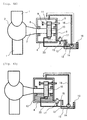
- Fig. 1A illustrates a state of the gearbox and the vicinity of the gearbox during energization, that is, while electric power required to operate the wind power generation station is supplied.
- Fig. 1B illustrates a state of the gearbox and the vicinity of the gearbox during a power failure, that is, while electric power required to operate the wind power generation station is not supplied.
- the gearbox 4 is connected to the rotor, which is configured to include the hub 2 and the plurality of blades 1, via a rotating shaft 7.
- the rotating shaft 7 is provided to pass through the inside of the gearbox 4.
- a relatively large gear 10 is attached to the rotating shaft 7.
- a plurality of bearings 8 are provided between the gearbox 4 and the rotating shaft 7 such that the rotating shaft 7 is capable of rotating relative to the gearbox 4 in a state where frictional resistance is applied much less therebetween.
- a relatively small gear 11 is provided in the gearbox 4, and rotates as a pair of the gears 10.
- the rotation of the rotating shaft 7 is increased by a gear ratio between the gear 10 and the gear 11, and thus a rotational speed transmitted to the generator is increased, and power generation efficiency is improved.
- a plurality of bearings 9 are provided between the gearbox 4 and a rotating shaft.
- gear 10 and the gear 11 When the gear 10 and the gear 11 rotate while being in mesh with each other, due to friction therebetween, the gear 10 or the gear 11 may wear away, or frictional heat may occur in the gearbox 4. It is necessary to supply lubricant into the gearbox 4 to reduce as much friction as possible between the gears or between the gears and the bearings.
- an oil tank 13 for storing lubricant 12 is provided outside of the gearbox 4.
- a lubricant pump 14 is provided in the oil tank 13 so as to supply the lubricant 12 to the gearbox 4.
- the lubricant pump 14 is connected to the gearbox 4 via an oil supply passage 16.
- the lubricant 12, which is discharged from the oil tank 13 by the lubricant pump 14, is injected into the gearbox 4 through the oil supply passage 16, and is applied to the gears, the bearings, and the like in the gearbox 4.
- An oil drain passage 15 is provided in a bottom portion of the gearbox 4 such that the lubricant in the gearbox 4 drains into the oil tank 13.
- An automatic valve A17 is provided on the oil drain passage 15 between the gearbox 4 and the oil tank 13.
- a so-called normally-closed type valve is used as the automatic valve A17. The valve is opened during energization, and is closed during a power failure.
- the lubricant pump 14 is connected to a backup power source 19 that supplies electric power to the lubricant pump 14 during a power failure. Even during a power failure, the lubricant pump 14 is capable of continuously supplying the lubricant 12 from the oil tank 13 to the gearbox 4 for a while.
- An uninterruptible power supply (UPS) or the like is used as the backup power source.
- a level gauge 18 is provided in the oil tank 13, and is a sensor that detects the volume of the lubricant 12. The operation of the lubricant pump 14 is controlled according to the height of the level of the lubricant 12 detected by the level gauge 18.
- the lubricant 12 is discharged from the oil tank 13 to the oil supply passage 16 by the lubricant pump 14.
- the lubricant which is supplied to the gearbox 4 through the oil supply passage 16, is injected into the gearbox 4, and is applied to the gears or the bearings in the gearbox 4.
- Electric power is supplied to the automatic valve A17 of the oil drain passage 15 provided in the bottom portion of the gearbox 4, and thus the automatic valve A17 is opened, and the lubricant, which has fallen to the bottom portion of the gearbox 4, drains into the oil tank 13 through the oil drain passage 15.
- the gearbox of the wind power generation station is operated in a dry sump lubrication manner.
- the lubricant pump 14 is connected to the backup power source 19, and thus the lubricant pump 14 is continuously operated, and the lubricant 12 is continuously supplied from the oil tank 13 to the gearbox 4. Meanwhile, the automatic valve A17 of the oil drain passage 15 is closed, and thus the lubricant 12 accumulated in the bottom portion of the gearbox 4 does not drain into the oil tank 13, and is accumulated in the gearbox 4.
- the level gauge 18 is provided in the oil tank 13 so as to detect the level of the lubricant 12.
- the level of the lubricant 12 in the oil tank 13 is lower than or equal to a predetermined value, that is, when the volume of the lubricant 12 in the oil tank 13 is less than a predetermined value, the lubricant pump 14 is stopped such that more than the lubricant 12 needed is prevented from being supplied into the gearbox 4.
- Fig. 2 is a flowchart illustrating the control of the operation of the lubricant pump 14 according to the level gauge 18. First, when a power failure occurs, the automatic valve A17 of the oil drain passage 15 is closed. (Closing of Valve Passage (Automatic))
- the level of the lubricant 12 in the oil tank (lubricant tank) 13 is detected by the level gauge 18, and it is determined whether the level is greater than or equal to the predetermined value.
- the lubricant pump 14 When it is determined that the level of the lubricant is greater than or equal to the predetermined value, the lubricant pump 14 is started up, and the lubricant 12 is continuously supplied into the gearbox 4 from the oil tank 13. In contrast, when it is determined that the level of the lubricant is less than or equal to the predetermined value, the lubricant pump 14 is stopped, and the supply of the lubricant 12 into the gearbox 4 from the oil tank 13 is stopped. Thereafter, the operation and the stopping of the lubricant pump 14 is controlled by continuously monitoring the level of the lubricant in the oil tank 13 using the level gauge 18, and continuously determining the position of an actual level relative to a predetermined level.
- the gearbox of the wind power generation station in the example is operated in a dry sump lubrication manner.
- the gearbox includes the oil tank and the lubricant pump outside of the gearbox, and the valve is provided at a lubricant drain port of the gearbox, and is closed when electric power is not supplied to the valve.
- the gearbox is operated in a lubricant-bath lubrication manner.
- the required volume of lubricant is supplied into the gearbox from the oil tank, a portion of the gears is immersed in the lubricant.
- the gearbox 4 has a structure in which the gearbox 4 is sufficiently sealed up to an increased level of the lubricant.
- the lubricant pump is operated by the backup power source, and supplies the lubricant into the gearbox until the required volume of lubricant is stored in the gearbox.
- the volume of the lubricant is managed by the level gauge, and when the lubricant returns into the lubricant tank from the gearbox due to the leakage of the valve, and the volume of the lubricant in the gearbox is insufficient, the lubricant pump is intermittently operated.
- the wind power generation station in the example is capable of taking advantage of merits of both the lubricant bath method and the dry sump method, and cancelling out the demerits thereof. That is, the gearbox is used by a dry sump method during a normal operation (energization), and thus the efficiency of the gearbox is high. The gearbox is operated by a lubricant bath method during a power failure, and thus it is possible to reduce the capacity of an emergency power source, that is, the backup power source.
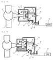
- Fig. 3A illustrates a state of the gearbox and the vicinity of the gearbox during energization, that is, when electric power required to operate the wind power generation station is supplied.
- Fig. 3B illustrates a state of the gearbox and the vicinity of the gearbox during a power failure, that is, when electric power required to operate the wind power generation station is not supplied.
- the wind power generation station in Example 2 is different from the wind power generation station in Example 1 in that the level gauge 18 for detecting the level of the lubricant 12 is provided in the gearbox 4.
- Example 1 as illustrated in Figs. 1A and 1B , the level gauge 18 is provided in the oil tank 13. In contrast, in Example 2, as illustrated in Figs. 3A and 3B , the level gauge 18 is provided in the gearbox 4. As described in Example 1, the operation of the lubricant pump 14 is controlled by using the level gauge 18 in the gearbox 4.
- a sensor like a level gauge is provided in the gearbox 4 so as to monitor the volume of the lubricant in the gearbox 4.
- a level detection signal which is supplied from the level gauge 18 already provided in the gearbox 4, for the controlling of the operation of the lubricant pump 14.
- the level gauge 18 When the level gauge 18 is provided in the oil tank 13, it is possible to accurately monitor the suction of the lubricant pump 14, and in contrast, when'the level gauge 18 is provided in the gearbox 4 or a casing, it is possible to more accurately monitor an immersed state of the gear 10 of the gearbox 4.
- the level gauges 18 may be respectively provided in both the oil tank 13 and the gearbox 4, and may be used for the controlling of the operation of the lubricant pump 14.
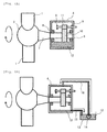
- Fig. 4A illustrates a state of the gearbox and the vicinity of the gearbox during energization, that is, when electric power required to operate the wind power generation station is supplied.
- Fig. 4B illustrates a state of the gearbox and the vicinity of the gearbox during a power failure, that is, when electric power required to operate the wind power generation station is not supplied.
- the wind power generation station in Example 3 is different from the wind power generation station in Example 1 in that drive force or electric power obtained from the rotation of the gear 10 in the gearbox 4 is supplied to the lubricant pump 14 instead of the backup power source which supplies electric power during a power failure.
- Example 1 as illustrated in Figs. 1A and 1B , the backup power source 19 is connected to the lubricant pump 14 so as to supply electric power during a power failure.
- Example 3 as illustrated in Figs. 4A and 4B , drive force or electric power obtained from the rotation of the gear 10 in the gearbox 4 is supplied to the lubricant pump 14 through a drive force transmission system 20. That is, the lubricant pump 14 is operated by a portion of rotational energy of the wind power generation station.
- a new gear is provided to mesh with the gear 10, and the rotation of the gear is transmitted to the lubricant pump 14 through the drive force transmission system 20 such that the lubricant pump 14 is operated.
- a mechanical pump is used to mechanically discharge the lubricant 12 through rotation.
- Example 3 even during a power failure, it is possible to operate the lubricant pump 14 without providing the backup power source like a UPS.
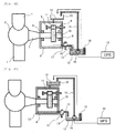
- Fig. 5A illustrates a state of the gearbox and the vicinity of the gearbox during energization, that is, when electric power required to operate the wind power generation station is supplied.
- Fig. 5B illustrates a state of the gearbox and the vicinity of the gearbox during a power failure, that is, when electric power required to operate the wind power generation station is not supplied.
- Example 4 The wind power generation station in Example 4 is different from the wind power generation station in Example 1 in that an oil supply system, through which the lubricant 12 is supplied into the gearbox 4 from the oil tank 13, is formed of two systems, that is, an oil supply passage 16 and an oil supply passage 22.
- Example 4 is different from Example 1 in that an automatic valve (three-way valve) B21 is provided in the oil supply system.
- the automatic valve B21 is opened in such a way that the lubricant 12 flows through the oil supply passage 16. At this time, the lubricant 12 does not flow through the oil supply passage 22.
- the oil supply passage 16 is connected to an upper surface of the gearbox 4 so that the lubricant 12 is capable of flowing to an upper side of the gearbox 4.
- the automatic valve B21 is opened in such a way that the lubricant 12 flows through the oil supply passage 22. At this time, the lubricant 12 does not flow through the oil supply passage 16.
- the oil supply passage 22 is connected to the gearbox 4, and the connection position of the oil supply passage 22 is lower than that of the oil supply passage 16.
- the wind power generation station in Example 4 has a structure in which the oil supply passage can be changed during energization and a power failure.
- the height of the supply passage of the lubricant 12 to the gearbox 4 is lowered, and as a result, it is possible to decrease the pump head of the lubricant pump 14, to supply the lubricant by using much less electric power or energy, and to reduce the capacity of a pump power source for a power failure, that is, the capacity of the backup power source.
- the following methods are effective in reducing the load of the lubricant pump 14: a method of decreasing pipe resistance by increasing a pipe diameter of the oil supply passage; a method of reducing the path of the oil supply passage as much as possible; and the like.
- Fig. 6A illustrates a state of the gearbox and the vicinity of the gearbox during energization, that is, when electric power required to operate the wind power generation station is supplied.
- Fig. 6B illustrates a state of the gearbox and the vicinity of the gearbox during a power failure, that is, when electric power required to operate the wind power generation station is not supplied.
- the wind power generation station in Example 5 is different from the wind power generation station in Example 1 in that an intermediate oil tank 22 is provided in the supply system (through which the lubricant 12 is supplied into the gearbox 4 from the oil tank 13) so as to be positioned higher than the gearbox 4 such that the lubricant 12 is capable of temporarily staying in the intermediate oil tank 22.
- the intermediate oil tank 22 is provided in the system for the supply of the lubricant to the gearbox 4, and thus during a power failure, the lubricant 12 is capable of temporarily staying at a position higher than that of the gearbox 4.
- the lubricant 12 accumulated in the intermediate oil tank 22 is supplied into the gearbox 4 due to gravity.
- Example 5 According to the structure of the wind power generation station in Example 5, it is possible to reduce the capacity of the backup power source 19 that supplies electric power to the lubricant pump 14 during a power failure.
- the present invention is not limited to these examples, and includes various modification examples. These examples have been described in detail for the purpose of easy description of the present invention, and the present invention is not limited to a case in which the entirety of the aforementioned configuration elements is included. A portion of the configuration elements of an example can be replaced with a portion of the configuration elements of another example, and the configuration elements of an example can be added to the configuration of another example. A portion of the configuration elements of each example can be added to, removed from, or replaced with a portion of the configuration elements of another example.
Landscapes
- Engineering & Computer Science (AREA)
- Life Sciences & Earth Sciences (AREA)
- Sustainable Development (AREA)
- Sustainable Energy (AREA)
- Chemical & Material Sciences (AREA)
- Combustion & Propulsion (AREA)
- Mechanical Engineering (AREA)
- General Engineering & Computer Science (AREA)
- Wind Motors (AREA)
- General Details Of Gearings (AREA)
- Connection Of Motors, Electrical Generators, Mechanical Devices, And The Like (AREA)
Abstract
Description
- The present invention relates to a wind power generation station, particularly, to a gearbox of a wind power generation station.
- In recent years, attention has been paid to a wind power generation station as a low-risk and environmentally friendly power generation method that does not emit greenhouse gases such as carbon dioxide, and is not exposed to radiation hazards compared to a thermal power plant or a nuclear power plant in the related art. In contrast, power generation cost is high, and it is necessary to further reduce the cost of the wind power generation station while ensuring safety.
- In order to reduce the cost of the wind power generation station, the enlargement of a wind turbine has been progressed, and an installation location has been moved from a land site to an offshore site.
- The drive system structure of the wind turbine is largely divided into structures with or without a gearbox. When the gearbox is provided, a relatively small generator is mounted in a nacelle so as to increase the rotational speed of a rotor. In contrast, when the gearbox is not provided, the structure of the wind turbine is relatively simple, but a large-sized generator is mounted on the outside of the nacelle in an exposed manner such that the large-sized generator generates electricity at the same rotational speed as that of the rotor.
- Offshore wind power generation using the gearbox is a main stream, and partly, a hydraulic transmission instead of the gearbox being used.
- The efficiency of the gearbox becomes a problem area in the enlargement of the wind turbine. The impact of heat loss is negligible as output increases, and the enlargement has an impact on a cooling device or the cost. An extra output equivalent to the loss is applied to the rotor, and thus the rotor requires extra strength.
- Technology disclosed in
PTL 1 is an example of the gearbox of the wind power generation station.PTL 1 discloses "the bearing lubricant supplying structure of the wind power generation station with a planetary gear type gearbox in which a planetary gear rotates, via a slide bearing, around a planetary pin (which serves as a rotating shaft) fixed to a carrier, in which the slide bearing is lubricated by supplying lubricant from a lubricant bath to a lower rotation region, and supplying the lubricant to an upper rotation region by injecting, via a nozzle, the lubricant that is pressure-fed from a lubricant source". - According to the bearing lubricant supplying structure of the wind power generation station, it is possible to reduce the number of components through the simplification of a lubricant supply method, and to reduce the cost through the simplification of an assembly structure.
- [PTL 1]
JP-A-2012-132333 - The efficiency of the gearbox of the large-sized wind turbine is improved by changing a lubricant supply method (refer to
Fig. 8A ) in the related art to a dry sump method (refer toFig. 8B ) so as to lubricate gears and bearings. - As illustrated in
Fig. 8A , according to the lubricant bath method, alubricant 12 stored in agearbox 4 is pumped by the rotation of agear 10 in thegearbox 4. Thelubricant 12 is circulated without the aid of a pump, but the efficiency is relatively bad due to the occurrence of pumping loss. - In contrast, according to the dry sump method illustrated in
Fig. 8B , alubricant pump 14 supplies thelubricant 12 only to lubricant requiring portions from anoil tank 13 installed outside of agearbox 4. Therefore, pumping loss for the lubricant is reduced, and the efficiency is good, but when necessary, the supply of the lubricant is required even during a power failure. - When the wind turbine is installed at an offshore site, a maintenance method during a power failure becomes a problem area. An installation project of the offshore wind turbine is a large-scale project, and thus a situation, in which the supply of electric power is stopped for a long period of time due to business trouble, occurs frequently. Even after the start of operation, the offshore wind turbine may stand by without the supply of electric power thereto for a long period of time due to a power failure or damage to an undersea cable, and a maintenance method becomes a problem area. As a countermeasure of these problems, typically, an emergency power supply device or a diesel powered generator is prepared.
- As described above, when the gearbox is used and the lubricant bath method is adopted in the wind turbine, there is a problem such as the efficiency being bad, and particularly, the problem becomes magnified as the wind turbine is enlarged. The gearbox with the dry sump lubrication system has merits in that it is not necessary to pump the lubricant, and the efficiency is good; however, the gearbox requires a backup power source for supplying the lubricant to the gears and the bearings during a power failure.
- The gearbox disclosed in
PTL 1 has a lubricant supply structure in which both the lubricant bath method and the dry sump method are adopted, but has a problem such as the internal structure of the gearbox being complicated, and from the viewpoint of cost or maintenance. - An object of the present invention is to provide a high-reliability wind power generation station at a reduced cost by mounting a gearbox in the wind power generation station, with the gearbox having a relatively simple structure and being capable of taking advantage of merits of both of a lubricant bath method and a dry sump method.
- Another object of the present invention is to provide the gearbox of the power wind generation station, which has a relatively simple structure and is capable of taking advantage of merits of both the lubricant bath method and the dry sump method.
- In order to solve the problems, according to an aspect of the present invention, there is provided a wind power generation station including: a rotor that includes a hub configured to convert wind power into rotational energy when wind blows against the hub, and a plurality of blades; a gearbox configured to increase the rotational speed of the rotor; a generator configured to convert the rotational energy, which is transmitted through the gearbox, into electric power; an oil tank configured to supply lubricant to the gearbox; and an oil circulation system configured to circulate the lubricant between the gearbox and the oil tank. The oil circulation system includes at least an oil supply system and an oil drain system for each system. The oil supply system includes a pump that discharges the lubricant. The oil drain system includes an automatic valve that is provided between the gearbox and the oil tank, and is closed during a power failure.
- According to another aspect of the present invention, there is provided a gearbox mounted in a wind power generation station, the increaser including: an oil tank configured to supply lubricant to the gearbox; and an oil circulation system configured to circulate the lubricant between the gearbox and the oil tank. The oil circulation system includes at least an oil supply system and an oil drain system for each system. The oil supply system includes a pump configured to discharge the lubricant. The oil drain system includes an automatic valve that is provided between the gearbox and the oil tank, and is closed during a power failure.
- According to the present invention, it is possible to realize the high-reliability wind power generation station at a reduced cost by mounting the gearbox in the wind power generation station, with the gearbox having a relatively simple structure and being capable of taking advantage of merits of both the lubricant bath method and the dry sump method.
- According to the present invention, it is possible to realize the gearbox of the wind power generation station, which has a relatively simple structure and is capable of taking advantage of merits of both the lubricant bath method and the dry sump method.
- Objects, configurations, and effects other than the aforementioned description are apparent from the description of examples given below.
-
- [
Fig. 1A] Fig. 1A is a view illustrating an outline of a gearbox of a wind power generation station in an embodiment of the present invention. - [
Fig. 1B] Fig. 1B is a view illustrating an outline of the gearbox of the wind power generation station in the embodiment of the present invention. - [
Fig. 2] Fig. 2 is a flowchart illustrating the operation of the gearbox of the wind power generation station in the embodiment of the present invention. - [
Fig. 3A] Fig. 3A is a view illustrating an outline of the gearbox of the wind power generation station in the embodiment of the present invention. - [
Fig. 3B] Fig. 3B is a view illustrating an outline of the gearbox of the wind power generation station in the embodiment of the present invention. - [
Fig. 4A] Fig. 4A is a view illustrating an outline of the gearbox of the wind power generation station in the embodiment of the present invention. - [
Fig. 4B] Fig. 4B is a view illustrating an outline of the gearbox of the wind power generation station in the embodiment of the present invention. - [
Fig. 5A] Fig. 5A is a view illustrating an outline of the gearbox of the wind power generation station in the embodiment of the present invention. - [
Fig. 5B] Fig. 5B is a view illustrating an outline of the gearbox of the wind power generation station in the embodiment of the present invention. - [
Fig. 6A] Fig. 6A is a view illustrating an outline of the gearbox of the wind power generation station in the embodiment of the present invention. - [
Fig. 6B] Fig. 6B is a view illustrating an outline of the gearbox of the wind power generation station in the embodiment of the present invention. - [
Fig. 7] Fig. 7 is a view illustrating an outline of the entirety of the wind power generation station in the embodiment of the present invention. - [
Fig. 8A] Fig. 8A is a view illustrating an outline of a gearbox of a wind power generation station in the related art. - [
Fig. 8B] Fig. 8B is a view illustrating an outline of the gearbox of the wind power generation station in the related art. - Hereinafter, examples of the present invention will be described with reference to the accompanying drawings. In the drawings, the same reference signs are assigned to the same configuration elements, and the detailed descriptions thereof will be omitted.
- First, an outline of the entirety of a wind power generation station in the example will be described with reference to
Fig. 7 . The example is described focused mainly on a downwind type wind power generation station; however, the present invention is not limited to the downwind type wind power generation station, and similarly, can be applied to an upwind type wind power generation station. A wind power generation station installed on the ground has the same configuration as that of a wind power generation station installed offshore, and thus a description will be given without discriminating the wind power generation stations installed on the ground or offshore. - As illustrated in
Fig. 7 , in the wind power generation station of the example, anacelle 3 is provided in an apex portion of atower 6 installed on the ground or offshore, and a gearbox, that is, agearbox 4 and a generator 5 are built into thenacelle 3. - A rotor is provided at one end of the
nacelle 3, and is configured to include ahub 2 and a plurality ofblades 1. Thehub 2 is connected to thegearbox 4 and the generator 5 via a rotating shaft. The plurality ofblades 1 rotate along with thehub 2 due to wind blowing against theblades 1 such that wind power is converted into rotational energy, the rotational energy is transmitted to the generator 5 via the rotating shaft and thegearbox 4, and electricity is generated. - Hereinafter, the structure of the gearbox of the wind power generation station in the example will be described with reference to
Figs. 1A and 1B. Fig. 1A illustrates a state of the gearbox and the vicinity of the gearbox during energization, that is, while electric power required to operate the wind power generation station is supplied.Fig. 1B illustrates a state of the gearbox and the vicinity of the gearbox during a power failure, that is, while electric power required to operate the wind power generation station is not supplied. - As illustrated in
Fig. 1A , thegearbox 4 is connected to the rotor, which is configured to include thehub 2 and the plurality ofblades 1, via arotating shaft 7. Therotating shaft 7 is provided to pass through the inside of thegearbox 4. - In the
gearbox 4, a relativelylarge gear 10 is attached to therotating shaft 7. A plurality ofbearings 8 are provided between thegearbox 4 and therotating shaft 7 such that therotating shaft 7 is capable of rotating relative to thegearbox 4 in a state where frictional resistance is applied much less therebetween. - A relatively
small gear 11 is provided in thegearbox 4, and rotates as a pair of thegears 10. The rotation of therotating shaft 7 is increased by a gear ratio between thegear 10 and thegear 11, and thus a rotational speed transmitted to the generator is increased, and power generation efficiency is improved. In order to reduce the frictional resistance of a rotating shaft against thegearbox 4, with thegear 11 being attached to the rotating shaft, a plurality ofbearings 9 are provided between thegearbox 4 and a rotating shaft. - When the
gear 10 and thegear 11 rotate while being in mesh with each other, due to friction therebetween, thegear 10 or thegear 11 may wear away, or frictional heat may occur in thegearbox 4. It is necessary to supply lubricant into thegearbox 4 to reduce as much friction as possible between the gears or between the gears and the bearings. - In the wind power generation station of the example, an
oil tank 13 for storinglubricant 12 is provided outside of thegearbox 4. Alubricant pump 14 is provided in theoil tank 13 so as to supply thelubricant 12 to thegearbox 4. Thelubricant pump 14 is connected to thegearbox 4 via anoil supply passage 16. Thelubricant 12, which is discharged from theoil tank 13 by thelubricant pump 14, is injected into thegearbox 4 through theoil supply passage 16, and is applied to the gears, the bearings, and the like in thegearbox 4. - An
oil drain passage 15 is provided in a bottom portion of thegearbox 4 such that the lubricant in thegearbox 4 drains into theoil tank 13. An automatic valve A17 is provided on theoil drain passage 15 between thegearbox 4 and theoil tank 13. A so-called normally-closed type valve is used as the automatic valve A17. The valve is opened during energization, and is closed during a power failure. - The
lubricant pump 14 is connected to abackup power source 19 that supplies electric power to thelubricant pump 14 during a power failure. Even during a power failure, thelubricant pump 14 is capable of continuously supplying thelubricant 12 from theoil tank 13 to thegearbox 4 for a while. An uninterruptible power supply (UPS) or the like is used as the backup power source. - A
level gauge 18 is provided in theoil tank 13, and is a sensor that detects the volume of thelubricant 12. The operation of thelubricant pump 14 is controlled according to the height of the level of thelubricant 12 detected by thelevel gauge 18. - As illustrated in
Fig. 1A , in the wind power generation station of the example, during energization, thelubricant 12 is discharged from theoil tank 13 to theoil supply passage 16 by thelubricant pump 14. The lubricant, which is supplied to thegearbox 4 through theoil supply passage 16, is injected into thegearbox 4, and is applied to the gears or the bearings in thegearbox 4. Electric power is supplied to the automatic valve A17 of theoil drain passage 15 provided in the bottom portion of thegearbox 4, and thus the automatic valve A17 is opened, and the lubricant, which has fallen to the bottom portion of thegearbox 4, drains into theoil tank 13 through theoil drain passage 15. - That is, in the example, as described above, during energization, the gearbox of the wind power generation station is operated in a dry sump lubrication manner.
- In contrast, as illustrated in
Fig. 1B , electric power is not supplied to the automatic valve A17 of theoil drain passage 15 during a power failure, and thus the automatic valve A17 is closed. - The
lubricant pump 14 is connected to thebackup power source 19, and thus thelubricant pump 14 is continuously operated, and thelubricant 12 is continuously supplied from theoil tank 13 to thegearbox 4. Meanwhile, the automatic valve A17 of theoil drain passage 15 is closed, and thus thelubricant 12 accumulated in the bottom portion of thegearbox 4 does not drain into theoil tank 13, and is accumulated in thegearbox 4. - As a result, when the volume of the accumulated lubricant is greater than or equal to a predetermined value, a portion of the
gear 10 is immersed in thelubricant 12, and thegearbox 4 is operated in a lubricant-bath lubrication manner. - As illustrated in
Fig. 1B , thelevel gauge 18 is provided in theoil tank 13 so as to detect the level of thelubricant 12. The level of thelubricant 12 in theoil tank 13 is lower than or equal to a predetermined value, that is, when the volume of thelubricant 12 in theoil tank 13 is less than a predetermined value, thelubricant pump 14 is stopped such that more than thelubricant 12 needed is prevented from being supplied into thegearbox 4. -
Fig. 2 is a flowchart illustrating the control of the operation of thelubricant pump 14 according to thelevel gauge 18. First, when a power failure occurs, the automatic valve A17 of theoil drain passage 15 is closed. (Closing of Valve Passage (Automatic)) - Subsequently, the level of the
lubricant 12 in the oil tank (lubricant tank) 13 is detected by thelevel gauge 18, and it is determined whether the level is greater than or equal to the predetermined value. - When it is determined that the level of the lubricant is greater than or equal to the predetermined value, the
lubricant pump 14 is started up, and thelubricant 12 is continuously supplied into thegearbox 4 from theoil tank 13. In contrast, when it is determined that the level of the lubricant is less than or equal to the predetermined value, thelubricant pump 14 is stopped, and the supply of thelubricant 12 into thegearbox 4 from theoil tank 13 is stopped. Thereafter, the operation and the stopping of thelubricant pump 14 is controlled by continuously monitoring the level of the lubricant in theoil tank 13 using thelevel gauge 18, and continuously determining the position of an actual level relative to a predetermined level. - As described above, during energization, that is, when electric power required to operate the wind power generation station is supplied, the gearbox of the wind power generation station in the example is operated in a dry sump lubrication manner. The gearbox includes the oil tank and the lubricant pump outside of the gearbox, and the valve is provided at a lubricant drain port of the gearbox, and is closed when electric power is not supplied to the valve.
- During a power failure, that is, when electric power required to operate the wind power generation station is not supplied, the gearbox is operated in a lubricant-bath lubrication manner. When the required volume of lubricant is supplied into the gearbox from the oil tank, a portion of the gears is immersed in the lubricant. The
gearbox 4 has a structure in which thegearbox 4 is sufficiently sealed up to an increased level of the lubricant. - During a power failure, the lubricant pump is operated by the backup power source, and supplies the lubricant into the gearbox until the required volume of lubricant is stored in the gearbox. The volume of the lubricant is managed by the level gauge, and when the lubricant returns into the lubricant tank from the gearbox due to the leakage of the valve, and the volume of the lubricant in the gearbox is insufficient, the lubricant pump is intermittently operated.
- The wind power generation station in the example is capable of taking advantage of merits of both the lubricant bath method and the dry sump method, and cancelling out the demerits thereof. That is, the gearbox is used by a dry sump method during a normal operation (energization), and thus the efficiency of the gearbox is high. The gearbox is operated by a lubricant bath method during a power failure, and thus it is possible to reduce the capacity of an emergency power source, that is, the backup power source.
- Only the automatic valve A17 is added to this system from the viewpoint of hardware, and a decrease in the reliability of the entirety of the system almost does not occur.
- As a result, it is possible to realize the high-reliability wind power generation station with a relatively simple structure at a reduced cost.
- The structure of the gearbox of the wind power generation station in Example 2 will be described with reference to
Figs. 3A and 3B. Fig. 3A illustrates a state of the gearbox and the vicinity of the gearbox during energization, that is, when electric power required to operate the wind power generation station is supplied.Fig. 3B illustrates a state of the gearbox and the vicinity of the gearbox during a power failure, that is, when electric power required to operate the wind power generation station is not supplied. - The wind power generation station in Example 2 is different from the wind power generation station in Example 1 in that the
level gauge 18 for detecting the level of thelubricant 12 is provided in thegearbox 4. - In Example 1, as illustrated in
Figs. 1A and 1B , thelevel gauge 18 is provided in theoil tank 13. In contrast, in Example 2, as illustrated inFigs. 3A and 3B , thelevel gauge 18 is provided in thegearbox 4. As described in Example 1, the operation of thelubricant pump 14 is controlled by using thelevel gauge 18 in thegearbox 4. - Typically, in many cases, a sensor like a level gauge is provided in the
gearbox 4 so as to monitor the volume of the lubricant in thegearbox 4. In Example 2, it is possible to simplify the structure of the gearbox without an additional provision of a level gauge by using a level detection signal, which is supplied from thelevel gauge 18 already provided in thegearbox 4, for the controlling of the operation of thelubricant pump 14. - When the
level gauge 18 is provided in theoil tank 13, it is possible to accurately monitor the suction of thelubricant pump 14, and in contrast,when'the level gauge 18 is provided in thegearbox 4 or a casing, it is possible to more accurately monitor an immersed state of thegear 10 of thegearbox 4. - Naturally, the level gauges 18 may be respectively provided in both the
oil tank 13 and thegearbox 4, and may be used for the controlling of the operation of thelubricant pump 14. - The structure of the gearbox of the wind power generation station in Example 3 will be described with reference to
Figs. 4A and 4B. Fig. 4A illustrates a state of the gearbox and the vicinity of the gearbox during energization, that is, when electric power required to operate the wind power generation station is supplied.Fig. 4B illustrates a state of the gearbox and the vicinity of the gearbox during a power failure, that is, when electric power required to operate the wind power generation station is not supplied. - The wind power generation station in Example 3 is different from the wind power generation station in Example 1 in that drive force or electric power obtained from the rotation of the
gear 10 in thegearbox 4 is supplied to thelubricant pump 14 instead of the backup power source which supplies electric power during a power failure. - In Example 1, as illustrated in
Figs. 1A and 1B , thebackup power source 19 is connected to thelubricant pump 14 so as to supply electric power during a power failure. In contrast, in Example 3, as illustrated inFigs. 4A and 4B , drive force or electric power obtained from the rotation of thegear 10 in thegearbox 4 is supplied to thelubricant pump 14 through a driveforce transmission system 20. That is, thelubricant pump 14 is operated by a portion of rotational energy of the wind power generation station. - For example, in order to obtain drive force or electric power to drive the
lubricant pump 14 from the rotation of thegear 10, a new gear is provided to mesh with thegear 10, and the rotation of the gear is transmitted to thelubricant pump 14 through the driveforce transmission system 20 such that thelubricant pump 14 is operated. In this case, as thelubricant pump 14, a mechanical pump is used to mechanically discharge thelubricant 12 through rotation. - In addition, it is possible to operate the
lubricant pump 14 by providing a small-sized generator, which meshes with thegear 10, in thegearbox 4, and transmitting electric power from the small-sized generator to thelubricant pump 14 through the driveforce transmission system 20. - According to the configuration of Example 3, even during a power failure, it is possible to operate the
lubricant pump 14 without providing the backup power source like a UPS. - The structure of the gearbox of the wind power generation station in Example 4 will be described with reference to
Figs. 5A and 5B. Fig. 5A illustrates a state of the gearbox and the vicinity of the gearbox during energization, that is, when electric power required to operate the wind power generation station is supplied.Fig. 5B illustrates a state of the gearbox and the vicinity of the gearbox during a power failure, that is, when electric power required to operate the wind power generation station is not supplied. - The wind power generation station in Example 4 is different from the wind power generation station in Example 1 in that an oil supply system, through which the
lubricant 12 is supplied into thegearbox 4 from theoil tank 13, is formed of two systems, that is, anoil supply passage 16 and anoil supply passage 22. In addition, Example 4 is different from Example 1 in that an automatic valve (three-way valve) B21 is provided in the oil supply system. - As illustrated in
Fig. 5A , during energization, that is, when electric power required to operate the wind power generation station is supplied, the automatic valve B21 is opened in such a way that thelubricant 12 flows through theoil supply passage 16. At this time, thelubricant 12 does not flow through theoil supply passage 22. Theoil supply passage 16 is connected to an upper surface of thegearbox 4 so that thelubricant 12 is capable of flowing to an upper side of thegearbox 4. - In contrast, as illustrated in
Fig. 5B , during a power failure, that is, when electric power required to operate the wind power generation station is not supplied, the automatic valve B21 is opened in such a way that thelubricant 12 flows through theoil supply passage 22. At this time, thelubricant 12 does not flow through theoil supply passage 16. Theoil supply passage 22 is connected to thegearbox 4, and the connection position of theoil supply passage 22 is lower than that of theoil supply passage 16. - As described above, the wind power generation station in Example 4 has a structure in which the oil supply passage can be changed during energization and a power failure. During a power failure, the height of the supply passage of the
lubricant 12 to thegearbox 4 is lowered, and as a result, it is possible to decrease the pump head of thelubricant pump 14, to supply the lubricant by using much less electric power or energy, and to reduce the capacity of a pump power source for a power failure, that is, the capacity of the backup power source. - For example, in addition to a method of lowering the position of the oil supply passage to a lower position as in the example, the following methods are effective in reducing the load of the lubricant pump 14: a method of decreasing pipe resistance by increasing a pipe diameter of the oil supply passage; a method of reducing the path of the oil supply passage as much as possible; and the like.
- The structure of the gearbox of the wind power generation station in Example 5 will be described with reference to
Figs. 6A and 6B. Fig. 6A illustrates a state of the gearbox and the vicinity of the gearbox during energization, that is, when electric power required to operate the wind power generation station is supplied.Fig. 6B illustrates a state of the gearbox and the vicinity of the gearbox during a power failure, that is, when electric power required to operate the wind power generation station is not supplied. - The wind power generation station in Example 5 is different from the wind power generation station in Example 1 in that an
intermediate oil tank 22 is provided in the supply system (through which thelubricant 12 is supplied into thegearbox 4 from the oil tank 13) so as to be positioned higher than thegearbox 4 such that thelubricant 12 is capable of temporarily staying in theintermediate oil tank 22. - As illustrated in
Fig. 6B , theintermediate oil tank 22 is provided in the system for the supply of the lubricant to thegearbox 4, and thus during a power failure, thelubricant 12 is capable of temporarily staying at a position higher than that of thegearbox 4. Thelubricant 12 accumulated in theintermediate oil tank 22 is supplied into thegearbox 4 due to gravity. - According to the structure of the wind power generation station in Example 5, it is possible to reduce the capacity of the
backup power source 19 that supplies electric power to thelubricant pump 14 during a power failure. - The present invention is not limited to these examples, and includes various modification examples. These examples have been described in detail for the purpose of easy description of the present invention, and the present invention is not limited to a case in which the entirety of the aforementioned configuration elements is included. A portion of the configuration elements of an example can be replaced with a portion of the configuration elements of another example, and the configuration elements of an example can be added to the configuration of another example. A portion of the configuration elements of each example can be added to, removed from, or replaced with a portion of the configuration elements of another example.
-
- 1: BLADE
- 2: HUB
- 3: NACELLE
- 4: GEARBOX
- 5: GENERATOR
- 6: TOWER
- 7: ROTATING SHAFT
- 8, 9: BEARING
- 10, 11: GEAR
- 12: LUBRICANT
- 13: OIL TANK
- 14: LUBRICANT PUMP
- 15: OIL DRAIN PASSAGE
- 16, 22: OIL SUPPLY PASSAGE
- 17: AUTOMATIC VALVE A
- 18: LEVEL GAUGE
- 19: BACKUP POWER SOURCE (UPS)
- 20: DRIVE FORCE TRANSMISSION SYSTEM
- 21: AUTOMATIC VALVE B (THREE-WAY VALVE)
- 22: INTERMEDIATE OIL TANK
Claims (14)
- A wind power generation station comprising:a rotor that includes a hub configured to convert wind power into rotational energy when wind blows against the hub (2), and a plurality of blades (1);a gearbox (4) configured to increase the rotational speed of the rotor;a generator (5) configured to convert the rotational energy, which is transmitted through the gearbox (4), into electric power;an oil tank (13) configured to supply lubricant to the gearbox (4); andan oil circulation system configured to circulate the lubricant between the gearbox (4) and the oil tank (13),wherein the oil circulation system includes at least an oil supply system and an oil drain system for each system,wherein the oil supply system includes a pump that discharges the lubricant, andwherein the oil drain system includes an automatic valve (17) that is provided between the gearbox (4) and the oil tank (13), and is closed during a power failure.
- The wind power generation station according to claim 1,
wherein the oil tank (13) includes a sensor configured to detect the volume of the lubricant in the oil tank (13), and
wherein during a power failure, the operation of the pump is controlled according to the volume of the lubricant detected by the sensor. - The wind power generation station according to claim 1,
wherein the gearbox (4) includes a sensor configured to detect the volume of the lubricant in the gearbox (4), and
wherein during a power failure, the operation of the pump is controlled according to the volume of the lubricant detected by the sensor. - The wind power generation station according to at least one of the claims 1 to 3,
wherein the wind power generation station includes a backup power source (19) configured to supply electric power during a power failure, and
wherein during a power failure, electric power is supplied to the pump from the backup power source (19). - The wind power generation station according to at least one of the claims 1 to 3,
wherein at least during a power failure, the pump is operated by a portion of the rotational energy of the wind power generation station. - The wind power generation station according to at least one of the claims 1 to 5,
wherein the oil supply system includes a first oil supply system through which the lubricant is supplied to the gearbox (4), and a second oil supply system which is positioned to be lower than the first oil supply system, and through which the lubricant is supplied to the gearbox (4), and
wherein during a power failure, the oil supply system is switched from the first oil supply system to the second oil supply system by an automatic three-way valve (21) provided in the oil supply system. - The wind power generation station according to at least one of the claims 1 to 5,
wherein the oil supply system includes an intermediate oil tank (22) which is positioned to be higher than the gearbox (4), and in which the lubricant temporarily stays. - A gearbox (4) mounted in a wind power generation station, the increaser comprising:an oil tank (13) configured to supply lubricant to the gearbox (4); andan oil circulation system configured to circulate the lubricant between the gearbox and the oil tank (13),wherein the oil circulation system includes at least an oil supply system and an oil drain system for each system,wherein the oil supply system includes a pump configured to discharge the lubricant, andwherein the oil drain system includes an automatic valve that is provided between the gearbox (4) and the oil tank (13), and is closed during a power failure.
- The gearbox (4) according to claim 8,
wherein the oil tank includes a sensor configured to detect the volume of the lubricant in the oil tank (13), and
wherein during a power failure, the operation of the pump is controlled according to the volume of the lubricant detected by the sensor. - The gearbox (4) according to claim 8,
wherein the gearbox (4) includes a sensor configured to detect the volume of the lubricant in the gearbox (4), and
wherein during a power failure, the operation of the pump is controlled according to the volume of the lubricant detected by the sensor. - The gearbox (4) according to at least one of the claims 8 to 10,
wherein during a power failure, electric power is supplied to the pump from a backup power source (19). - The gearbox (4) according to at least one of the claims 8 to 10,
wherein at least during a power failure, the pump is operated by a portion of rotational energy generated by the wind power generation station in which the gearbox (4) is mounted. - The gearbox (4) according to at least one of the claims 8 to 12,
wherein the oil supply system includes a first oil supply system through which the lubricant is supplied to the gearbox (4), and a second oil supply system which is positioned to be lower than the first oil supply system, and through which the lubricant is supplied to the gearbox (4), and
wherein during a power failure, the oil supply system is switched from the first oil supply system to the second oil supply system by an automatic three-way valve provided in the oil supply system. - The gearbox (4) according to at least one of the claims 8 to 12,
wherein the oil supply system includes an intermediate oil tank (22) which is positioned to be higher than the gearbox (4), and in which the lubricant temporarily stays.
Applications Claiming Priority (1)
| Application Number | Priority Date | Filing Date | Title |
|---|---|---|---|
| JP2014266952A JP6386375B2 (en) | 2014-12-29 | 2014-12-29 | Wind power generation equipment and gearbox |
Publications (1)
| Publication Number | Publication Date |
|---|---|
| EP3040553A1 true EP3040553A1 (en) | 2016-07-06 |
Family
ID=55066420
Family Applications (1)
| Application Number | Title | Priority Date | Filing Date |
|---|---|---|---|
| EP15202842.9A Withdrawn EP3040553A1 (en) | 2014-12-29 | 2015-12-28 | Wind power generation station and gearbox |
Country Status (2)
| Country | Link |
|---|---|
| EP (1) | EP3040553A1 (en) |
| JP (1) | JP6386375B2 (en) |
Cited By (19)
| Publication number | Priority date | Publication date | Assignee | Title |
|---|---|---|---|---|
| CN106015541A (en) * | 2016-07-21 | 2016-10-12 | 中国电建集团贵阳勘测设计研究院有限公司 | Method and system for monitoring and filtering oil sample of gearbox of wind driven generator |
| EP3388668A1 (en) * | 2017-04-12 | 2018-10-17 | Adwen GmbH | Lubrication system for a drive train of a wind turbine |
| EP3388666A1 (en) * | 2017-04-12 | 2018-10-17 | Adwen GmbH | Lubrication system for a drive train of a wind turbine, wind turbine and method of lubrication |
| CN110475970A (en) * | 2017-04-12 | 2019-11-19 | 艾德温股份有限公司 | Lubrication system for the drive train of a wind turbine |
| AT521687B1 (en) * | 2018-12-13 | 2020-04-15 | Miba Gleitlager Austria Gmbh | Gondola for a wind turbine |
| CN112303200A (en) * | 2020-11-23 | 2021-02-02 | 沈阳工程学院 | Transmission device of mechanical pump set of wind power gear box |
| WO2021139860A1 (en) * | 2020-01-08 | 2021-07-15 | Vestas Wind Systems A/S | Main bearing housing of a wind turbine |
| US11371208B2 (en) | 2018-04-25 | 2022-06-28 | Komatsu Ltd. | Work equipment for motor grader |
| CN115574251A (en) * | 2022-10-19 | 2023-01-06 | 中车株洲电力机车研究所有限公司 | An offshore wind turbine gearbox lubrication system |
| US11746757B2 (en) | 2018-12-13 | 2023-09-05 | Miba Gleitlager Austria Gmbh | Nacelle for a wind turbine |
| US11754054B2 (en) | 2018-06-25 | 2023-09-12 | Vestas Wind Systems A/S | Pump system for lubricating components of a wind turbine |
| US11761429B2 (en) | 2018-12-13 | 2023-09-19 | Miba Gleitlager Austria Gmbh | Slide bearing, in particular for a gearbox of a wind turbine |
| US11808247B2 (en) | 2018-12-13 | 2023-11-07 | Miba Gleitlager Austria Gmbh | Planetary gear set for a wind turbine |
| US11940006B2 (en) | 2018-12-13 | 2024-03-26 | Miba Gleitlager Austria Gmbh | Method for changing a sliding bearing element of a rotor bearing of a wind turbine, and nacelle for a wind turbine |
| US12049873B2 (en) | 2020-01-08 | 2024-07-30 | Vestas Wind Systems A/S | Main bearing housing of a wind turbine |
| US12110874B2 (en) | 2018-12-13 | 2024-10-08 | Miba Gleitlager Austria Gmbh | Nacelle for a wind turbine |
| CN119551584A (en) * | 2025-01-22 | 2025-03-04 | 江苏奥德减速机有限公司 | A reducer for a safety ladder winch |
| DE102024103036A1 (en) * | 2024-02-02 | 2025-08-07 | Schaeffler Technologies AG & Co. KG | Bearing device for a wind turbine for hydrodynamically supporting a rotor shaft with a rotor axis |
| WO2025208466A1 (en) * | 2024-04-03 | 2025-10-09 | Envision Energy Co., Ltd. | Gearbox unit and wind power generation device |
Families Citing this family (3)
| Publication number | Priority date | Publication date | Assignee | Title |
|---|---|---|---|---|
| CN108050236A (en) * | 2017-11-15 | 2018-05-18 | 芜湖乐佳自动化机械有限公司 | A kind of energy-efficient property gear-box |
| CN110701288B (en) * | 2019-09-12 | 2020-12-25 | 珠海格力电器股份有限公司 | RV reducer for displaying lubricating states of cycloidal teeth and pin teeth and displaying method |
| CN112610872A (en) * | 2020-11-30 | 2021-04-06 | 福建海电运维科技有限责任公司 | Intelligent lubricating oil system based on offshore platform generator set design |
Citations (3)
| Publication number | Priority date | Publication date | Assignee | Title |
|---|---|---|---|---|
| GB2201200A (en) * | 1987-01-23 | 1988-08-24 | Bergische Stahlindustrie | Lubrication of gear means for a wind energy installation |
| JP2012132333A (en) | 2010-12-20 | 2012-07-12 | Mitsubishi Heavy Ind Ltd | Bearing oil supply structure for wind power generation apparatus |
| GB2500118A (en) * | 2012-03-10 | 2013-09-11 | Romax Technology Ltd | Gravity fed lubrication arrangement for a rotating machine |
Family Cites Families (2)
| Publication number | Priority date | Publication date | Assignee | Title |
|---|---|---|---|---|
| JP3322072B2 (en) * | 1994-08-12 | 2002-09-09 | トヨタ自動車株式会社 | Power transmission lubrication system |
| JP2014240667A (en) * | 2013-06-11 | 2014-12-25 | Ntn株式会社 | In-wheel motor drive unit |
-
2014
- 2014-12-29 JP JP2014266952A patent/JP6386375B2/en active Active
-
2015
- 2015-12-28 EP EP15202842.9A patent/EP3040553A1/en not_active Withdrawn
Patent Citations (3)
| Publication number | Priority date | Publication date | Assignee | Title |
|---|---|---|---|---|
| GB2201200A (en) * | 1987-01-23 | 1988-08-24 | Bergische Stahlindustrie | Lubrication of gear means for a wind energy installation |
| JP2012132333A (en) | 2010-12-20 | 2012-07-12 | Mitsubishi Heavy Ind Ltd | Bearing oil supply structure for wind power generation apparatus |
| GB2500118A (en) * | 2012-03-10 | 2013-09-11 | Romax Technology Ltd | Gravity fed lubrication arrangement for a rotating machine |
Cited By (34)
| Publication number | Priority date | Publication date | Assignee | Title |
|---|---|---|---|---|
| CN106015541A (en) * | 2016-07-21 | 2016-10-12 | 中国电建集团贵阳勘测设计研究院有限公司 | Method and system for monitoring and filtering oil sample of gearbox of wind driven generator |
| CN110475970A (en) * | 2017-04-12 | 2019-11-19 | 艾德温股份有限公司 | Lubrication system for the drive train of a wind turbine |
| EP3388666A1 (en) * | 2017-04-12 | 2018-10-17 | Adwen GmbH | Lubrication system for a drive train of a wind turbine, wind turbine and method of lubrication |
| WO2018189328A1 (en) * | 2017-04-12 | 2018-10-18 | Adwen Gmbh | Lubrication system for a drive train of a wind turbine |
| WO2018189323A1 (en) * | 2017-04-12 | 2018-10-18 | Adwen Gmbh | Lubrication system for a drive train of a wind turbine, wind turbine and method of lubricating |
| CN110475969A (en) * | 2017-04-12 | 2019-11-19 | 艾德温股份有限公司 | Lubrication system for a drive train of a wind turbine |
| CN110573729A (en) * | 2017-04-12 | 2019-12-13 | 艾德温股份有限公司 | Lubrication system for drive train of wind turbine, wind turbine and lubrication method |
| EP3388668A1 (en) * | 2017-04-12 | 2018-10-17 | Adwen GmbH | Lubrication system for a drive train of a wind turbine |
| US11512681B2 (en) | 2017-04-12 | 2022-11-29 | Dwen Gmbh | Lubrication system for a drive train of a wind turbine, wind turbine and method of lubricating |
| US11480155B2 (en) | 2017-04-12 | 2022-10-25 | Adwen Gmbh | Lubrication system for a drive train of a wind turbine |
| US10975850B2 (en) | 2017-04-12 | 2021-04-13 | Adwen Gmbh | Lubrication system for a drive train of a wind turbine |
| US11371208B2 (en) | 2018-04-25 | 2022-06-28 | Komatsu Ltd. | Work equipment for motor grader |
| US11754054B2 (en) | 2018-06-25 | 2023-09-12 | Vestas Wind Systems A/S | Pump system for lubricating components of a wind turbine |
| AT521687B1 (en) * | 2018-12-13 | 2020-04-15 | Miba Gleitlager Austria Gmbh | Gondola for a wind turbine |
| US12110874B2 (en) | 2018-12-13 | 2024-10-08 | Miba Gleitlager Austria Gmbh | Nacelle for a wind turbine |
| US12196184B2 (en) | 2018-12-13 | 2025-01-14 | Miba Gleitlager Austria Gmbh | Nacelle for a wind turbine |
| CN113167324A (en) * | 2018-12-13 | 2021-07-23 | 米巴滑动轴承奥地利有限公司 | Nacelle for a wind power plant |
| WO2020118332A1 (en) * | 2018-12-13 | 2020-06-18 | Miba Gleitlager Austria Gmbh | Nacelle for a wind turbine |
| US11940006B2 (en) | 2018-12-13 | 2024-03-26 | Miba Gleitlager Austria Gmbh | Method for changing a sliding bearing element of a rotor bearing of a wind turbine, and nacelle for a wind turbine |
| US11808247B2 (en) | 2018-12-13 | 2023-11-07 | Miba Gleitlager Austria Gmbh | Planetary gear set for a wind turbine |
| CN116066469A (en) * | 2018-12-13 | 2023-05-05 | 米巴滑动轴承奥地利有限公司 | Nacelles for wind power plants |
| EP4215772A1 (en) * | 2018-12-13 | 2023-07-26 | Miba Gleitlager Austria GmbH | Nacelle for a wind turbine |
| US11746757B2 (en) | 2018-12-13 | 2023-09-05 | Miba Gleitlager Austria Gmbh | Nacelle for a wind turbine |
| AT521687A4 (en) * | 2018-12-13 | 2020-04-15 | Miba Gleitlager Austria Gmbh | Gondola for a wind turbine |
| US11761429B2 (en) | 2018-12-13 | 2023-09-19 | Miba Gleitlager Austria Gmbh | Slide bearing, in particular for a gearbox of a wind turbine |
| US12049873B2 (en) | 2020-01-08 | 2024-07-30 | Vestas Wind Systems A/S | Main bearing housing of a wind turbine |
| US12104580B2 (en) | 2020-01-08 | 2024-10-01 | Vestas Wind Systems A/S | Main bearing housing of a wind turbine |
| WO2021139860A1 (en) * | 2020-01-08 | 2021-07-15 | Vestas Wind Systems A/S | Main bearing housing of a wind turbine |
| CN112303200B (en) * | 2020-11-23 | 2023-04-25 | 沈阳工程学院 | A wind power gearbox mechanical pump transmission device |
| CN112303200A (en) * | 2020-11-23 | 2021-02-02 | 沈阳工程学院 | Transmission device of mechanical pump set of wind power gear box |
| CN115574251A (en) * | 2022-10-19 | 2023-01-06 | 中车株洲电力机车研究所有限公司 | An offshore wind turbine gearbox lubrication system |
| DE102024103036A1 (en) * | 2024-02-02 | 2025-08-07 | Schaeffler Technologies AG & Co. KG | Bearing device for a wind turbine for hydrodynamically supporting a rotor shaft with a rotor axis |
| WO2025208466A1 (en) * | 2024-04-03 | 2025-10-09 | Envision Energy Co., Ltd. | Gearbox unit and wind power generation device |
| CN119551584A (en) * | 2025-01-22 | 2025-03-04 | 江苏奥德减速机有限公司 | A reducer for a safety ladder winch |
Also Published As
| Publication number | Publication date |
|---|---|
| JP6386375B2 (en) | 2018-09-05 |
| JP2016125587A (en) | 2016-07-11 |
Similar Documents
| Publication | Publication Date | Title |
|---|---|---|
| EP3040553A1 (en) | Wind power generation station and gearbox | |
| CN102121524B (en) | The lubrication of fluid turbine gear-box during idling or grid loss | |
| US11619210B2 (en) | Gearbox system for a wind turbine, wind turbine with a gearbox system, and method for operating a gearbox system | |
| EP2325486A1 (en) | Wind driven electric power generator | |
| JP6352777B2 (en) | Wind power generator operation method | |
| EP2479429B1 (en) | A wind turbine and a method for powering one or more hydraulic pitch actuators | |
| EP2541057B1 (en) | Oil level maintenance system | |
| GB2500118A (en) | Gravity fed lubrication arrangement for a rotating machine | |
| KR20100126766A (en) | Wind power generator | |
| KR20200015458A (en) | Marine energy generation device and its marine energy generation leakage protection device | |
| EP3775635B1 (en) | Wind turbine drivetrain component with low friction radial shaft seal | |
| CN113551030A (en) | Filter system for a wind turbine and method for replacing an oil filter thereof | |
| JP7394494B2 (en) | Sealing systems used in ocean energy power generation devices | |
| WO2013182355A1 (en) | Method for lubricating a gearbox for a wind turbine | |
| CN106640527A (en) | Hydraulic control system and wind power generating set | |
| EP2402590A1 (en) | Three-bladed wind turbine device for small spaces | |
| CN102840107A (en) | Retention systems | |
| KR101264592B1 (en) | Wind power generator | |
| AU2008331348A1 (en) | Wind turbine generator | |
| KR101369968B1 (en) | Apparatus for monitoring bearing and wind power generator including the same | |
| TW201727054A (en) | Wind power generation system |
Legal Events
| Date | Code | Title | Description |
|---|---|---|---|
| PUAI | Public reference made under article 153(3) epc to a published international application that has entered the european phase |
Free format text: ORIGINAL CODE: 0009012 |
|
| 17P | Request for examination filed |
Effective date: 20160205 |
|
| AK | Designated contracting states |
Kind code of ref document: A1 Designated state(s): AL AT BE BG CH CY CZ DE DK EE ES FI FR GB GR HR HU IE IS IT LI LT LU LV MC MK MT NL NO PL PT RO RS SE SI SK SM TR |
|
| AX | Request for extension of the european patent |
Extension state: BA ME |
|
| STAA | Information on the status of an ep patent application or granted ep patent |
Free format text: STATUS: EXAMINATION IS IN PROGRESS |
|
| 17Q | First examination report despatched |
Effective date: 20180413 |
|
| GRAP | Despatch of communication of intention to grant a patent |
Free format text: ORIGINAL CODE: EPIDOSNIGR1 |
|
| STAA | Information on the status of an ep patent application or granted ep patent |
Free format text: STATUS: GRANT OF PATENT IS INTENDED |
|
| INTG | Intention to grant announced |
Effective date: 20181126 |
|
| STAA | Information on the status of an ep patent application or granted ep patent |
Free format text: STATUS: THE APPLICATION IS DEEMED TO BE WITHDRAWN |
|
| 18D | Application deemed to be withdrawn |
Effective date: 20190409 |