EP3040543A1 - Method to control the temperature of the exhaust gases of a supercharged internal combustion engine - Google Patents
Method to control the temperature of the exhaust gases of a supercharged internal combustion engine Download PDFInfo
- Publication number
- EP3040543A1 EP3040543A1 EP15197676.8A EP15197676A EP3040543A1 EP 3040543 A1 EP3040543 A1 EP 3040543A1 EP 15197676 A EP15197676 A EP 15197676A EP 3040543 A1 EP3040543 A1 EP 3040543A1
- Authority
- EP
- European Patent Office
- Prior art keywords
- air
- scav
- fuel ratio
- exhaust
- exhaust gases
- Prior art date
- Legal status (The legal status is an assumption and is not a legal conclusion. Google has not performed a legal analysis and makes no representation as to the accuracy of the status listed.)
- Granted
Links
Images

Classifications
-
- F—MECHANICAL ENGINEERING; LIGHTING; HEATING; WEAPONS; BLASTING
- F01—MACHINES OR ENGINES IN GENERAL; ENGINE PLANTS IN GENERAL; STEAM ENGINES
- F01N—GAS-FLOW SILENCERS OR EXHAUST APPARATUS FOR MACHINES OR ENGINES IN GENERAL; GAS-FLOW SILENCERS OR EXHAUST APPARATUS FOR INTERNAL-COMBUSTION ENGINES
- F01N3/00—Exhaust or silencing apparatus having means for purifying, rendering innocuous, or otherwise treating exhaust
- F01N3/02—Exhaust or silencing apparatus having means for purifying, rendering innocuous, or otherwise treating exhaust for cooling, or for removing solid constituents of, exhaust
- F01N3/05—Exhaust or silencing apparatus having means for purifying, rendering innocuous, or otherwise treating exhaust for cooling, or for removing solid constituents of, exhaust by means of air, e.g. by mixing exhaust with air
-
- F—MECHANICAL ENGINEERING; LIGHTING; HEATING; WEAPONS; BLASTING
- F02—COMBUSTION ENGINES; HOT-GAS OR COMBUSTION-PRODUCT ENGINE PLANTS
- F02D—CONTROLLING COMBUSTION ENGINES
- F02D41/00—Electrical control of supply of combustible mixture or its constituents
- F02D41/0002—Controlling intake air
- F02D41/0007—Controlling intake air for control of turbo-charged or super-charged engines
-
- F—MECHANICAL ENGINEERING; LIGHTING; HEATING; WEAPONS; BLASTING
- F01—MACHINES OR ENGINES IN GENERAL; ENGINE PLANTS IN GENERAL; STEAM ENGINES
- F01N—GAS-FLOW SILENCERS OR EXHAUST APPARATUS FOR MACHINES OR ENGINES IN GENERAL; GAS-FLOW SILENCERS OR EXHAUST APPARATUS FOR INTERNAL-COMBUSTION ENGINES
- F01N13/00—Exhaust or silencing apparatus characterised by constructional features
- F01N13/08—Other arrangements or adaptations of exhaust conduits
- F01N13/10—Other arrangements or adaptations of exhaust conduits of exhaust manifolds
-
- F—MECHANICAL ENGINEERING; LIGHTING; HEATING; WEAPONS; BLASTING
- F02—COMBUSTION ENGINES; HOT-GAS OR COMBUSTION-PRODUCT ENGINE PLANTS
- F02B—INTERNAL-COMBUSTION PISTON ENGINES; COMBUSTION ENGINES IN GENERAL
- F02B37/00—Engines characterised by provision of pumps driven at least for part of the time by exhaust
-
- F—MECHANICAL ENGINEERING; LIGHTING; HEATING; WEAPONS; BLASTING
- F02—COMBUSTION ENGINES; HOT-GAS OR COMBUSTION-PRODUCT ENGINE PLANTS
- F02B—INTERNAL-COMBUSTION PISTON ENGINES; COMBUSTION ENGINES IN GENERAL
- F02B77/00—Component parts, details or accessories, not otherwise provided for
- F02B77/08—Safety, indicating, or supervising devices
- F02B77/085—Safety, indicating, or supervising devices with sensors measuring combustion processes, e.g. knocking, pressure, ionization, combustion flame
- F02B77/086—Sensor arrangements in the exhaust, e.g. for temperature, misfire, air/fuel ratio, oxygen sensors
-
- F—MECHANICAL ENGINEERING; LIGHTING; HEATING; WEAPONS; BLASTING
- F02—COMBUSTION ENGINES; HOT-GAS OR COMBUSTION-PRODUCT ENGINE PLANTS
- F02D—CONTROLLING COMBUSTION ENGINES
- F02D41/00—Electrical control of supply of combustible mixture or its constituents
- F02D41/02—Circuit arrangements for generating control signals
- F02D41/14—Introducing closed-loop corrections
- F02D41/1438—Introducing closed-loop corrections using means for determining characteristics of the combustion gases; Sensors therefor
- F02D41/1444—Introducing closed-loop corrections using means for determining characteristics of the combustion gases; Sensors therefor characterised by the characteristics of the combustion gases
- F02D41/1454—Introducing closed-loop corrections using means for determining characteristics of the combustion gases; Sensors therefor characterised by the characteristics of the combustion gases the characteristics being an oxygen content or concentration or the air-fuel ratio
-
- F—MECHANICAL ENGINEERING; LIGHTING; HEATING; WEAPONS; BLASTING
- F02—COMBUSTION ENGINES; HOT-GAS OR COMBUSTION-PRODUCT ENGINE PLANTS
- F02D—CONTROLLING COMBUSTION ENGINES
- F02D41/00—Electrical control of supply of combustible mixture or its constituents
- F02D41/02—Circuit arrangements for generating control signals
- F02D41/14—Introducing closed-loop corrections
- F02D41/1438—Introducing closed-loop corrections using means for determining characteristics of the combustion gases; Sensors therefor
- F02D41/1444—Introducing closed-loop corrections using means for determining characteristics of the combustion gases; Sensors therefor characterised by the characteristics of the combustion gases
- F02D41/1454—Introducing closed-loop corrections using means for determining characteristics of the combustion gases; Sensors therefor characterised by the characteristics of the combustion gases the characteristics being an oxygen content or concentration or the air-fuel ratio
- F02D41/1458—Introducing closed-loop corrections using means for determining characteristics of the combustion gases; Sensors therefor characterised by the characteristics of the combustion gases the characteristics being an oxygen content or concentration or the air-fuel ratio with determination means using an estimation
-
- F—MECHANICAL ENGINEERING; LIGHTING; HEATING; WEAPONS; BLASTING
- F02—COMBUSTION ENGINES; HOT-GAS OR COMBUSTION-PRODUCT ENGINE PLANTS
- F02D—CONTROLLING COMBUSTION ENGINES
- F02D41/00—Electrical control of supply of combustible mixture or its constituents
- F02D41/02—Circuit arrangements for generating control signals
- F02D41/18—Circuit arrangements for generating control signals by measuring intake air flow
-
- F—MECHANICAL ENGINEERING; LIGHTING; HEATING; WEAPONS; BLASTING
- F02—COMBUSTION ENGINES; HOT-GAS OR COMBUSTION-PRODUCT ENGINE PLANTS
- F02B—INTERNAL-COMBUSTION PISTON ENGINES; COMBUSTION ENGINES IN GENERAL
- F02B25/00—Engines characterised by using fresh charge for scavenging cylinders
-
- F—MECHANICAL ENGINEERING; LIGHTING; HEATING; WEAPONS; BLASTING
- F02—COMBUSTION ENGINES; HOT-GAS OR COMBUSTION-PRODUCT ENGINE PLANTS
- F02B—INTERNAL-COMBUSTION PISTON ENGINES; COMBUSTION ENGINES IN GENERAL
- F02B29/00—Engines characterised by provision for charging or scavenging not provided for in groups F02B25/00, F02B27/00 or F02B33/00 - F02B39/00; Details thereof
- F02B29/06—After-charging, i.e. supplementary charging after scavenging
-
- F—MECHANICAL ENGINEERING; LIGHTING; HEATING; WEAPONS; BLASTING
- F02—COMBUSTION ENGINES; HOT-GAS OR COMBUSTION-PRODUCT ENGINE PLANTS
- F02D—CONTROLLING COMBUSTION ENGINES
- F02D13/00—Controlling the engine output power by varying inlet or exhaust valve operating characteristics, e.g. timing
- F02D13/02—Controlling the engine output power by varying inlet or exhaust valve operating characteristics, e.g. timing during engine operation
- F02D13/0261—Controlling the valve overlap
-
- F—MECHANICAL ENGINEERING; LIGHTING; HEATING; WEAPONS; BLASTING
- F02—COMBUSTION ENGINES; HOT-GAS OR COMBUSTION-PRODUCT ENGINE PLANTS
- F02D—CONTROLLING COMBUSTION ENGINES
- F02D41/00—Electrical control of supply of combustible mixture or its constituents
- F02D41/0002—Controlling intake air
- F02D2041/001—Controlling intake air for engines with variable valve actuation
-
- F—MECHANICAL ENGINEERING; LIGHTING; HEATING; WEAPONS; BLASTING
- F02—COMBUSTION ENGINES; HOT-GAS OR COMBUSTION-PRODUCT ENGINE PLANTS
- F02D—CONTROLLING COMBUSTION ENGINES
- F02D23/00—Controlling engines characterised by their being supercharged
-
- F—MECHANICAL ENGINEERING; LIGHTING; HEATING; WEAPONS; BLASTING
- F02—COMBUSTION ENGINES; HOT-GAS OR COMBUSTION-PRODUCT ENGINE PLANTS
- F02M—SUPPLYING COMBUSTION ENGINES IN GENERAL WITH COMBUSTIBLE MIXTURES OR CONSTITUENTS THEREOF
- F02M26/00—Engine-pertinent apparatus for adding exhaust gases to combustion-air, main fuel or fuel-air mixture, e.g. by exhaust gas recirculation [EGR] systems
- F02M26/02—EGR systems specially adapted for supercharged engines
- F02M26/04—EGR systems specially adapted for supercharged engines with a single turbocharger
- F02M26/05—High pressure loops, i.e. wherein recirculated exhaust gas is taken out from the exhaust system upstream of the turbine and reintroduced into the intake system downstream of the compressor
-
- F—MECHANICAL ENGINEERING; LIGHTING; HEATING; WEAPONS; BLASTING
- F02—COMBUSTION ENGINES; HOT-GAS OR COMBUSTION-PRODUCT ENGINE PLANTS
- F02M—SUPPLYING COMBUSTION ENGINES IN GENERAL WITH COMBUSTIBLE MIXTURES OR CONSTITUENTS THEREOF
- F02M26/00—Engine-pertinent apparatus for adding exhaust gases to combustion-air, main fuel or fuel-air mixture, e.g. by exhaust gas recirculation [EGR] systems
- F02M26/02—EGR systems specially adapted for supercharged engines
- F02M26/04—EGR systems specially adapted for supercharged engines with a single turbocharger
- F02M26/06—Low pressure loops, i.e. wherein recirculated exhaust gas is taken out from the exhaust downstream of the turbocharger turbine and reintroduced into the intake system upstream of the compressor
-
- Y—GENERAL TAGGING OF NEW TECHNOLOGICAL DEVELOPMENTS; GENERAL TAGGING OF CROSS-SECTIONAL TECHNOLOGIES SPANNING OVER SEVERAL SECTIONS OF THE IPC; TECHNICAL SUBJECTS COVERED BY FORMER USPC CROSS-REFERENCE ART COLLECTIONS [XRACs] AND DIGESTS
- Y02—TECHNOLOGIES OR APPLICATIONS FOR MITIGATION OR ADAPTATION AGAINST CLIMATE CHANGE
- Y02T—CLIMATE CHANGE MITIGATION TECHNOLOGIES RELATED TO TRANSPORTATION
- Y02T10/00—Road transport of goods or passengers
- Y02T10/10—Internal combustion engine [ICE] based vehicles
- Y02T10/12—Improving ICE efficiencies
Definitions
- the present invention relates to a method to control the temperature of the exhaust gases of a supercharged internal combustion engine.
- an internal combustion engine supercharged by means of a turbocharger supercharging system comprises a number of cylinders, each connected to an intake manifold by means of at least one respective intake valve and to an exhaust manifold by means of at least one respective exhaust valve.
- the intake manifold receives a gas mixture comprising both exhaust gases and fresh air, i.e. air coming from the outside through an intake pipe.
- the exhaust manifold is connected to an exhaust pipe, which feeds the exhaust gases produced by the combustion to an exhaust system, which releases the gases produced by the combustion into the atmosphere and normally comprises at least one catalytic converter (if necessary, provided with a diesel particulate filter) and at least one silencer (not shown) arranged downstream of the catalytic converter.
- the internal combustion engine supercharging system comprises a turbocharger provided with a turbine, which is arranged along the exhaust pipe so as to rotate at a high speed due to the action of the exhaust gases expelled from the cylinders, and a supercharger, which is arranged along the intake pipe and is mechanically connected to the turbine so as to be caused to rotate by the turbine itself in order to increase the pressure of the air present in the feeding pipe.
- the internal combustion engine is controlled by an electronic control unit, which controls the operation of all the components of the internal combustion engine.
- the electronic control unit is designed to control the supercharged internal combustion engine for the operation in its normal operating mode and in its "scavenging" operating mode, which involves a significant passage of air from the intake manifold directly into the exhaust pipe.
- the passage of air from the intake manifold directly into the exhaust pipe is obtained by properly timing the intake valves connecting each cylinder to the intake manifold and the exhaust valves connecting each cylinder to the exhaust manifold, so as to allow fresh air to directly flow from the intake manifold to the exhaust manifold and, hence, to the exhaust pipe of the internal combustion engine.
- turbocharger lag phenomenon also known as turbo-lag
- the object of the present invention is to provide a method to control the temperature of the exhaust gases of a supercharged internal combustion engine, which is not affected by the drawbacks of the prior art and, at the same time, is easy and cheap to be implemented.
- number 1 indicates, as a whole, an internal combustion engine supercharged by means of a turbocharger supercharging system.
- the internal combustion engine 1 comprises four injectors 2, which directly inject fuel, preferably gasoline, into four cylinders 3, each connected to an intake manifold 4 by means of at least one respective intake valve 4* and to an exhaust manifold 5 by means of at least one respective exhaust valve 5*.
- the intake manifold 4 receives a gas mixture comprising both exhaust gases (as described more in detail below) and fresh air, i.e. air coming from the outside through an intake pipe 6, which is provided with an air filter 7 for the fresh air flow and is regulated by a throttle valve 8. Along the intake pipe 6, downstream of the air filter 7, there is also provided an air flow meter 7*, which is designed to detect the mass of the flow of fresh air taken in by the internal combustion engine 1.
- the exhaust manifold 5 is connected to an exhaust pipe 10, which feeds the exhaust gases produced by the combustion to an exhaust system, which releases the gases produced by the combustion into the atmosphere and normally comprises at least one catalytic converter 11 (if necessary, provided with a diesel particulate filter) and at least one silencer (not shown) arranged downstream of the catalytic converter 11.
- the supercharging system of the internal combustion engine 1 comprises a turbocharger 12 provided with a turbine 13, which is arranged along the exhaust pipe 10 so as to rotate at a high speed due to the action of the exhaust gases expelled from the cylinders 3, and a supercharger 14, which is arranged along the intake pipe 6 and is mechanically connected to the turbine 13 so as to be caused to rotate by the turbine 13 itself in order to increase the pressure of the air present in the feeding pipe 6.
- a bypass pipe 15 which is connected in parallel to the supercharger 13 so as to have its ends connected upstream and downstream of the supercharger 13 itself; along the bypass pipe 15 there is provided a wastegate valve 16, which is designed to adjust the flow rate of the exhaust gases flowing through the bypass pipe 15 and is controlled by a solenoid valve 17.
- the internal combustion engine 1 comprises, furthermore, a high pressure circuit EGR HP , which comprises, in turn, a bypass pipe connected in parallel to the assembly consisting of the four cylinders 3, the intake manifold 4 and the exhaust manifold 5.
- EGR HP high pressure circuit
- a bypass pipe connected in parallel to the assembly consisting of the four cylinders 3, the intake manifold 4 and the exhaust manifold 5.
- a blowoff valve 19 which is designed to adjust the flow rate of the exhaust gases flowing through the bypass pipe 18 and is controlled by an EGR solenoid valve 20.
- a heat exchanger 21 which fulfils the function of cooling the gases flowing out of the exhaust manifold 5.
- the internal combustion engine 1 is controlled by an electronic control unit 22, which controls the operation of all the components of the internal combustion engine 1.
- the electronic control unit 22 is connected to a sensor 23 measuring the temperature and the pressure of the gas mixture present in the intake manifold 4, to a sensor 24 measuring the number of revolutions per minute of the internal combustion engine 1, and to a sensor 25 (typically a UHEGO or UEGO linear oxygen sensor - which is known and not described below) measuring the air/fuel ratio of the exhaust gases upstream of the catalytic converter 11.
- the internal combustion engine 1 comprises a low pressure circuit EGR LP , which comprises, in turn, a bypass pipe 26 arranged along the exhaust pope 10; the bypass pipe 26 is connected in parallel to the turbocharger 12.
- EGR LP low pressure circuit
- the bypass pipe 26 is connected in parallel to the turbocharger 12.
- an EGR valve 27 which is designed to adjust the flow rate of the exhaust gases flowing through the bypass pipe 26.
- a heat exchanger 29 which fulfils the function of cooling the gases flowing out of the exhaust manifold 5 and into the supercharger 14.
- the electronic control unit 22 is connected to a sensor 30 which measures the quantity of oxygen present in the gas mixture flowing in the intake pipe 6 and is arranged along the intake pipe upstream both of the intercooler 9 and of the throttle valve 8.
- the measure of the quantity of oxygen present in the gas mixture flowing in the intake pipe 6 is used by the electronic control nit 22 to determine the flow rate of the exhaust gases of the low pressure circuit EGR LP .
- the electronic control unit 22 is designed to control the supercharged internal combustion engine 1 for the operation in its normal operating mode and in its "scavenging" operating mode, which involves a significant passage of air from the intake manifold 4 directly into the exhaust pipe 10 of the internal combustion engine 1.
- the passage of air from the intake manifold 4 directly into the exhaust pipe 10 is obtained by properly timing the intake valves (not shown) connecting each cylinder 3 to the intake manifold 4 and the exhaust valves (not shown) connecting each cylinder 3 to the exhaust manifold 5, so as to allow fresh air to directly flow from the intake manifold 4 to the exhaust manifold 5 and, hence, to the exhaust pipe 10 of the internal combustion engine 1.
- the intake valves (not shown) connecting each cylinder 3 to the intake manifold 4 and the exhaust valves (not shown) connecting each cylinder 3 to the exhaust manifold 5 can be operated by means of a known actuator, for example a VVT ( Variable Valve Timing ) actuator, or also with an electromagnetic camless actuator or an electro-hydraulic actuator.
- a known actuator for example a VVT ( Variable Valve Timing ) actuator, or also with an electromagnetic camless actuator or an electro-hydraulic actuator.
- the electronic control unit 22 is also designed to control the supercharged internal combustion engine 1 so as to increase the mass and volume flow rate of the air and/or exhaust gases flowing through the supercharger 14 and the turbine 13, relative to the air flow rate actually used by the supercharged internal combustion engine during the combustion to generate the desired power.
- the temperature of the exhaust gases is generated by two contributions: the first contribution derives from the heat of the mass of fuel that was not involved in the combustion taking place inside the cylinder 3 and reacts, in the exhaust manifold 5, with the oxygen of the flow rate m air_scav of scavenging air, the second contribution, on the other hand, derives from the heat generated by the residual oxygen of the flow rate m air_scav of scavenging air that does not react with the mass of fuel that was not involved in the combustion taking place inside the cylinder 3 and potentially reacts with combustion residues.
- the electronic control unit 22 is designed to control the supercharged internal combustion engine 1 so as to limit - as much as possible - both the first contribution and the second contribution, namely to limit - as much as possible - the input of heat deriving both from the mass of fuel that was not involved in the combustion taking place inside the cylinder 3 and and reacts, in the exhaust manifold 5, with the oxygen of the flow rate m air_scav of scavenging air and from the residual oxygen of the flow rate m air_scav of scavenging air that does not react with the mass of fuel that was not involved in the combustion taking place inside the cylinder 3 and potentially reacts with combustion residues.
- the electronic control unit 22 is designed to limit the heat generated by the mass of fuel that was not involved in the combustion taking place inside the cylinder 3 and reacts, in the exhaust manifold 5, with the oxygen of the flow rate m air_scav of scavenging air.
- ⁇ min m air_cyl / F st A st * m f ⁇ min minimum air/fuel ratio that can be obtained in the exhaust gases upstream of the catalytic converter 11; A st / F st stoichiometric ratio of the fuel being used; m f flow rate of fuel involved in the combustion taking place inside the cylinder 3; and m air_cyl flow rate of fuel that is involved in the combustion taking place inside the cylinder 3 and reacts with the flow rate m f of fuel.
- ⁇ min m air_cyl c p_exh * ⁇ T max - k i + ⁇ h * / F st A st m air_cyl ⁇ h * / F st A st - c p_exh * ⁇ T max * / F st A st + m air_cyl ⁇ h * / F st A st - k i - c p_exh * ⁇ T max * / F st A st + m air_cyl ⁇ h * / F st A st - k i - c p_exh * ⁇ T max * / F st A st
- the electronic control unit 22 is designed to learn the value of the air/fuel ratio ⁇ meas of the exhaust gases upstream of the catalytic converter 11 provided by the sensor 25 and to compare it with a reference value of the air/fuel ratio ⁇ target of the exhaust gases upstream of the catalytic converter 11.
- the electronic control unit 22 is designed to calculate the difference between the value of the air/fuel ratio ⁇ meas of the exhaust gases upstream of the catalytic converter 11 provided by the sensor 25 and the reference value of the air/fuel ratio ⁇ target of the exhaust gases upstream of the catalytic converter 11.
- the reference value of the air/fuel ratio ⁇ target of the exhaust gases upstream of the catalytic converter 11 is variable based on the flow rate m air_scav of air that is not involved in the combustion taking place inside the cylinders 3 and flows directly from the intake manifold 4 into the exhaust pipe 10.
- the reference value of the air/fuel ratio ⁇ target is determined based on the operating condition to be taken on by the operation of the internal combustion engine 1.
- the reference value of the air/fuel ratio ⁇ target is variable based on the engine point and on the thermal state of the internal combustion engine 1 (normally defined starting from the measure of the temperature of the cooling liquid).
- the electronic control unit 22 is designed to exploit as much as possible, in a given condition, the potential enthalpy drop ⁇ h generated by the "scavenging" operating mode so as to favour the turbocharger 12 (in other words, the the reference value of the air/fuel ratio ⁇ target leans towards the minimum air/fuel ratio ⁇ min ) or, alternatively, to heat the catalytic converter 11 or to restore the oxygen content, for example after an operating step with a basically rich mixture (in other words, the reference value of the air/fuel ratio ⁇ target is equal to 1 or is basically lean).
- an interval of safety values is defined for the operation of the supercharged internal combustion engine 1 in the "scavenging" operating mode.
- said interval of safety values for the operation of the supercharged internal combustion engine 1 in the "scavenging” operating mode is defined by an upper threshold value UTV LIMIT_SCAV and by a lower threshold value LTV LIMIT_SCAV .
- the electronic control unit 22 is designed to compare the air/fuel ratio measure error ⁇ ⁇ _scav with the interval of safety values for the operation of the supercharged internal combustion engine 1 in the "scavenging” operating mode, i.e. with the upper threshold value UTV LIMIT_SCAV and with the lower threshold value LTV LIMIT_SCAV .
- the electronic control unit 22 is designed to carry on with the operation of the internal combustion engine 1 in the "scavenging" operating mode.
- the electronic control unit 22 is designed to limit the operation of the internal combustion engine 1 in the "scavenging" operating mode.
- the electronic control unit 22 is designed to limit the flow rate m air_scav of air that is not involved in the combustion taking place inside the cylinders 3 and flows directly from the intake manifold 4 into the exhaust pipe 10, if the air/fuel ratio ⁇ meas of the exhaust gases detected by the sensor 25 does not lie within the interval of safety values defined by the pair of threshold values UTV LIMIT_SCAV , LTV LIMIT_SCAV .
- an interval of inhibition values is defined, outside which the operation of the supercharged internal combustion engine 1 in the "scavenging" operating mode must be inhibited.
- said interval of inhibition values for the operation of the supercharged internal combustion engine 1 in the "scavenging" operating mode is defined by an upper threshold value UTV INHIB_SCAV and by a lower threshold value LTV INHIB_SCAV .
- the electronic control unit 22 is designed to compare the air/fuel ratio measure error ⁇ ⁇ _scav with the interval of inhibition values for the operation of the supercharged internal combustion engine 1 in the "scavenging" operating mode, i.e.
- the electronic control unit 22 is designed to carry on with the operation of the internal combustion engine 1 in the "scavenging" operating mode.
- the electronic control unit 22 is designed to stop the operation of the internal combustion engine 1 in the "scavenging" operating mode.
- the upper threshold value UTV INHIB_SCAV is greater than the upper threshold value UTV LIMIT_SCAV and the lower threshold value LTV INHIB_SCAV is greater (in absolute value) than the lower threshold value LTV LIMIT_SCAV .
- the interval of inhibition values, outside which the operation of the supercharged internal combustion engine 1 in the "scavenging" operating mode must be inhibited is wider than the interval of safety value, outside which the operation of the supercharged internal combustion engine 1 in the "scavenging" operating mode must be limited.
- an interval of closed-loop values is defined, outside which the air/fuel ratio must be controlled in an open-loop operating mode.
- said interval of closed-loop values for the operation of the supercharged internal combustion engine 1 in the "scavenging" operating mode is defined by an upper threshold value UTV OL_SCAV and by a lower threshold value LTV OL_SCAV .
- the electronic control unit 22 is designed to compare the air/fuel ratio measure error ⁇ ⁇ _scav with the interval of closed-loop values for the operation of the supercharged internal combustion engine 1 in the "scavenging" operating mode, i.e.
- the electronic control unit 22 is designed to control the air/fuel ratio during the operation of the internal combustion engine 1 in the "scavenging" operating mode in closed-loop.
- the electronic control unit 22 is designed to control the air/fuel ratio during the operation of the internal combustion engine 1 in the "scavenging" operating mode in open-loop.
- the upper threshold value UTV OL_SCAV is smaller both than the upper threshold value UTV INHIB_SCAV and than the upper threshold value UTV LIMIT_SCAV ; whereas the lower threshold value LTV OL_SCAV is greater (in absolute value) both than the lower threshold value LTV INHIB_SCAV and then lower threshold value LTV LIMIT_SCAV .
- the electronic control unit 22 is designed to carry out a further check on the value of the air/fuel ratio ⁇ meas of the exhaust gases upstream of the catalytic converter 11 provided by the sensor 25.
- the electronic control unit 22 is configured to filter the value of the air/fuel ratio ⁇ meas of the exhaust gases upstream of the catalytic converter 11 provided by the sensor 25 and to compare it with the minimum air/fuel ratio ⁇ min that can be obtained in the exhaust gases upstream of the catalytic converter 11 during the operation of the internal combustion engine 1 in the scavenging operating mode, as calculated through the equation [11] set forth in the description above.
- the electronic control unit 22 is configured to carry on with the operation of the internal combustion engine 1 in the "scavenging" operating mode.
- the electronic control unit 22 is configured to limit the operation of the internal combustion engine 1 in the "scavenging" operating mode.
- the electronic control unit 22 is designed to limit the flow rate m air_scav of air that is not involved in the combustion taking place inside the cylinders 3 and flows directly from the intake manifold 4 into the exhaust pipe 10, if the air/fuel ratio ⁇ meas of the exhaust gases detected by the sensor 25 becomes smaller than the minimum air/fuel ratio ⁇ min .
- the electronic control unit 22 is configured to carry out a further check on the minimum air/fuel ratio ⁇ min that can be obtained in the exhaust gases upstream of the catalytic converter 11 during the operation of the internal combustion engine 1 in the scavenging operating mode, as calculated through the equation [11] set forth in the description above.
- the electronic control unit 22 is designed to compare the minimum air/fuel ratio ⁇ min that can be obtained in the exhaust gases upstream of the catalytic converter 11 during the operation of the internal combustion engine 1 in the scavenging operating mode, as calculated through the equation [11] set forth in the description above, with a safety value SV (usually smaller than 1) of the minimum air/fuel ratio ⁇ min that can be obtained in the exhaust gases upstream of the catalytic converter 11 during the operation of the internal combustion engine 1, which is calculated in a preliminary adjustment and set up phase and substantially lies in a neighbourhood smaller than 1.
- the electronic control unit 22 is designed to carry on with the operation of the internal combustion engine 1 in the "scavenging" operating mode.
- the electronic control unit 22 is designed to stop the operation of the internal combustion engine 1 in the "scavenging" operating mode.
- the method described above to control the temperature of the exhaust gases has some advantages. In particular, it ensures a small computing load for the electronic control unit 22 and avoids high thermal stresses for the components of the exhaust system during the operation in the "scavenging" operating mode of the internal combustion engine 1.
Landscapes
- Engineering & Computer Science (AREA)
- Chemical & Material Sciences (AREA)
- Combustion & Propulsion (AREA)
- Mechanical Engineering (AREA)
- General Engineering & Computer Science (AREA)
- Health & Medical Sciences (AREA)
- Chemical Kinetics & Catalysis (AREA)
- Toxicology (AREA)
- Electrical Control Of Air Or Fuel Supplied To Internal-Combustion Engine (AREA)
- Combined Controls Of Internal Combustion Engines (AREA)
- Output Control And Ontrol Of Special Type Engine (AREA)
Abstract
Description
- The present invention relates to a method to control the temperature of the exhaust gases of a supercharged internal combustion engine.
- As it is known, an internal combustion engine supercharged by means of a turbocharger supercharging system comprises a number of cylinders, each connected to an intake manifold by means of at least one respective intake valve and to an exhaust manifold by means of at least one respective exhaust valve. The intake manifold receives a gas mixture comprising both exhaust gases and fresh air, i.e. air coming from the outside through an intake pipe. The exhaust manifold is connected to an exhaust pipe, which feeds the exhaust gases produced by the combustion to an exhaust system, which releases the gases produced by the combustion into the atmosphere and normally comprises at least one catalytic converter (if necessary, provided with a diesel particulate filter) and at least one silencer (not shown) arranged downstream of the catalytic converter.
- The internal combustion engine supercharging system comprises a turbocharger provided with a turbine, which is arranged along the exhaust pipe so as to rotate at a high speed due to the action of the exhaust gases expelled from the cylinders, and a supercharger, which is arranged along the intake pipe and is mechanically connected to the turbine so as to be caused to rotate by the turbine itself in order to increase the pressure of the air present in the feeding pipe.
- The internal combustion engine is controlled by an electronic control unit, which controls the operation of all the components of the internal combustion engine. In particular, the electronic control unit is designed to control the supercharged internal combustion engine for the operation in its normal operating mode and in its "scavenging" operating mode, which involves a significant passage of air from the intake manifold directly into the exhaust pipe.
- Typically, the passage of air from the intake manifold directly into the exhaust pipe is obtained by properly timing the intake valves connecting each cylinder to the intake manifold and the exhaust valves connecting each cylinder to the exhaust manifold, so as to allow fresh air to directly flow from the intake manifold to the exhaust manifold and, hence, to the exhaust pipe of the internal combustion engine.
- The "scavenging" operating mode of the supercharged internal combustion engine permits a reduction in the turbocharger lag (phenomenon also known as turbo-lag), thus increasing the enthalpy drop available to the turbocharger, though it becomes extremely important to control the temperature of the exhaust system in a reliable manner, so as to avoid causing damages to the exhaust system itself and, in particular, to the catalytic converter and the silencer.
- The object of the present invention is to provide a method to control the temperature of the exhaust gases of a supercharged internal combustion engine, which is not affected by the drawbacks of the prior art and, at the same time, is easy and cheap to be implemented.
- According to the present invention, there is provided a method to control the temperature of the exhaust gases of a supercharged internal combustion engine according to the appended claims.
- The present invention will now be described with reference to the accompanying drawings, which show a nonlimiting embodiment thereof, wherein:
-
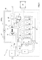
figure 1 schematically shows a supercharged internal combustion engine provided with an electronic control unit implementing the method according to the present invention; -
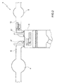
figure 2 schematically shows a cylinder of the supercharged internal combustion engine offigure 1 ; and -
figure 3 shows the development of the air/fuel ratio in the exhaust system of the supercharged internal combustion engine offigure 1 . - In
figure 1 ,number 1 indicates, as a whole, an internal combustion engine supercharged by means of a turbocharger supercharging system. - The
internal combustion engine 1 comprises fourinjectors 2, which directly inject fuel, preferably gasoline, into fourcylinders 3, each connected to anintake manifold 4 by means of at least onerespective intake valve 4* and to anexhaust manifold 5 by means of at least onerespective exhaust valve 5*. - The
intake manifold 4 receives a gas mixture comprising both exhaust gases (as described more in detail below) and fresh air, i.e. air coming from the outside through anintake pipe 6, which is provided with anair filter 7 for the fresh air flow and is regulated by athrottle valve 8. Along theintake pipe 6, downstream of theair filter 7, there is also provided anair flow meter 7*, which is designed to detect the mass of the flow of fresh air taken in by theinternal combustion engine 1. - Along the
intake pipe 6 there is provided anintercooler 9, which fulfils the function of cooling the air taken in and is preferably built-in in theintake manifold 4. Theexhaust manifold 5 is connected to anexhaust pipe 10, which feeds the exhaust gases produced by the combustion to an exhaust system, which releases the gases produced by the combustion into the atmosphere and normally comprises at least one catalytic converter 11 (if necessary, provided with a diesel particulate filter) and at least one silencer (not shown) arranged downstream of thecatalytic converter 11. - The supercharging system of the
internal combustion engine 1 comprises aturbocharger 12 provided with aturbine 13, which is arranged along theexhaust pipe 10 so as to rotate at a high speed due to the action of the exhaust gases expelled from thecylinders 3, and asupercharger 14, which is arranged along theintake pipe 6 and is mechanically connected to theturbine 13 so as to be caused to rotate by theturbine 13 itself in order to increase the pressure of the air present in thefeeding pipe 6. - Along the
exhaust pipe 10 there is provided abypass pipe 15, which is connected in parallel to thesupercharger 13 so as to have its ends connected upstream and downstream of thesupercharger 13 itself; along thebypass pipe 15 there is provided awastegate valve 16, which is designed to adjust the flow rate of the exhaust gases flowing through thebypass pipe 15 and is controlled by asolenoid valve 17. - The
internal combustion engine 1 comprises, furthermore, a high pressure circuit EGRHP, which comprises, in turn, a bypass pipe connected in parallel to the assembly consisting of the fourcylinders 3, theintake manifold 4 and theexhaust manifold 5. Along thebypass pipe 18 there is provided ablowoff valve 19, which is designed to adjust the flow rate of the exhaust gases flowing through thebypass pipe 18 and is controlled by anEGR solenoid valve 20. Along thebypass pipe 18, downstream of theblowoff valve 19, there is provided aheat exchanger 21, which fulfils the function of cooling the gases flowing out of theexhaust manifold 5. - The
internal combustion engine 1 is controlled by anelectronic control unit 22, which controls the operation of all the components of theinternal combustion engine 1. Theelectronic control unit 22 is connected to asensor 23 measuring the temperature and the pressure of the gas mixture present in theintake manifold 4, to asensor 24 measuring the number of revolutions per minute of theinternal combustion engine 1, and to a sensor 25 (typically a UHEGO or UEGO linear oxygen sensor - which is known and not described below) measuring the air/fuel ratio of the exhaust gases upstream of thecatalytic converter 11. - Finally, the
internal combustion engine 1 comprises a low pressure circuit EGRLP, which comprises, in turn, abypass pipe 26 arranged along theexhaust pope 10; thebypass pipe 26 is connected in parallel to theturbocharger 12. Along thebypass pipe 26 there is provided anEGR valve 27, which is designed to adjust the flow rate of the exhaust gases flowing through thebypass pipe 26. Along thebypass pipe 26, upstream of thevalve 27, there is also provided aheat exchanger 29, which fulfils the function of cooling the gases flowing out of theexhaust manifold 5 and into thesupercharger 14. - Finally, the
electronic control unit 22 is connected to asensor 30 which measures the quantity of oxygen present in the gas mixture flowing in theintake pipe 6 and is arranged along the intake pipe upstream both of theintercooler 9 and of thethrottle valve 8. - The measure of the quantity of oxygen present in the gas mixture flowing in the
intake pipe 6 is used by theelectronic control nit 22 to determine the flow rate of the exhaust gases of the low pressure circuit EGRLP. - Hereinafter you will find a description of the way in which the
electronic control unit 22 control the temperature of the exhaust gases through the measurement of the air/flow ratio of the exhaust gases upstream of thecatalytic converter 11, which is provided by thesensor 25. - The
electronic control unit 22 is designed to control the superchargedinternal combustion engine 1 for the operation in its normal operating mode and in its "scavenging" operating mode, which involves a significant passage of air from theintake manifold 4 directly into theexhaust pipe 10 of theinternal combustion engine 1. - Typically, the passage of air from the
intake manifold 4 directly into theexhaust pipe 10 is obtained by properly timing the intake valves (not shown) connecting eachcylinder 3 to theintake manifold 4 and the exhaust valves (not shown) connecting eachcylinder 3 to theexhaust manifold 5, so as to allow fresh air to directly flow from theintake manifold 4 to theexhaust manifold 5 and, hence, to theexhaust pipe 10 of theinternal combustion engine 1. It is clear that the intake valves (not shown) connecting eachcylinder 3 to theintake manifold 4 and the exhaust valves (not shown) connecting eachcylinder 3 to theexhaust manifold 5 can be operated by means of a known actuator, for example a VVT (Variable Valve Timing) actuator, or also with an electromagnetic camless actuator or an electro-hydraulic actuator. - According to a further embodiment, the
electronic control unit 22 is also designed to control the superchargedinternal combustion engine 1 so as to increase the mass and volume flow rate of the air and/or exhaust gases flowing through thesupercharger 14 and theturbine 13, relative to the air flow rate actually used by the supercharged internal combustion engine during the combustion to generate the desired power. - According to
figure 2 , in case of a "scavenging" configuration, the temperature of the exhaust gases is generated by two contributions: the first contribution derives from the heat of the mass of fuel that was not involved in the combustion taking place inside thecylinder 3 and reacts, in theexhaust manifold 5, with the oxygen of the flow rate mair_scav of scavenging air, the second contribution, on the other hand, derives from the heat generated by the residual oxygen of the flow rate mair_scav of scavenging air that does not react with the mass of fuel that was not involved in the combustion taking place inside thecylinder 3 and potentially reacts with combustion residues. - In order to avoid an excessive increase of the temperature of the exhaust gases, the
electronic control unit 22 is designed to control the superchargedinternal combustion engine 1 so as to limit - as much as possible - both the first contribution and the second contribution, namely to limit - as much as possible - the input of heat deriving both from the mass of fuel that was not involved in the combustion taking place inside thecylinder 3 and and reacts, in theexhaust manifold 5, with the oxygen of the flow rate mair_scav of scavenging air and from the residual oxygen of the flow rate mair_scav of scavenging air that does not react with the mass of fuel that was not involved in the combustion taking place inside thecylinder 3 and potentially reacts with combustion residues. In other words, based on the flow rate mair_scav of scavenging air, theelectronic control unit 22 is designed to limit the heat generated by the mass of fuel that was not involved in the combustion taking place inside thecylinder 3 and reacts, in theexhaust manifold 5, with the oxygen of the flow rate mair_scav of scavenging air. - Given the flow rate mair_scav of scavenging air, the heat balance in the exhaust system cam be calculated as follows:

cp_exh specific heat in the exhaust system;
mexh flow rate in the exhaust system;
Δ Tmax maximum temperature difference in the exhaust system;
mf_exh flow rate of fuel that was not involved in the combustion taking place inside thecylinder 3 and reacts, in theexhaust manifold 5, with the oxygen of the flow rate mair_scav of scavenging air;
ki lower heating value of the fuel being used;
Ast / Fst stoichiometric ratio of the fuel being used;
mair_scav flow rate of scavenging air; and
Δ h enthalpy drop. - The flow rate mexh in the exhaust system can be expressed as follows:

mexh flow rate in the exhaust system;
mair_scav flow rate of scavenging air;
mf flow rate of fuel involved in the combustion taking place inside thecylinder 3;
mair_cyl flow rate of fuel that is involved in the combustion taking place inside thecylinder 3 and reacts with the flow rate mf of fuel. - Inserting the equation [2] in the balance [1], you obtain that:

- The flow rate mf_exh of fuel that was not involved in the combustion taking place inside the
cylinder 3 and reacts, in theexhaust manifold 5, with the oxygen of the flow rate mair_scav of scavenging air an be xpressed as follows:
mf_exh flow rate of fuel that was not involved in the combustion inside thecylinder 3 and reacts, in theexhaust manifold 5, with the oxygen of the flow rate mair_scav of scavenging air;
Ast / Fst stoichiometric ratio of the fuel being used;
mf flow rate of fuel involved in the combustion taking place inside thecylinder 3; and
mair_cyl flow rate of fuel that is involved in the combustion taking place inside thecylinder 3 and reacts with the flow rate mf of fuel. - Inserting the equation [4] in the balance [3], the result is:

- From the equation [5], with some simple passages, you can obtain that:

- The minimum air/fuel ratio λmin that can be obtained in the exhaust gases upstream of the
catalytic converter 11 during the operation of theinternal combustion engine 1 in the scavenging configuration is established by the expression:
λ min minimum air/fuel ratio that can be obtained in the exhaust gases upstream of thecatalytic converter 11;
Ast / Fst stoichiometric ratio of the fuel being used;
mf flow rate of fuel involved in the combustion taking place inside thecylinder 3; and
mair_cyl flow rate of fuel that is involved in the combustion taking place inside thecylinder 3 and reacts with the flow rate mf of fuel. - The minimum air/fuel ratio λmin that can be obtained in the exhaust gases upstream of the
catalytic converter 11 during the operation of theinternal combustion engine 1 in the scavenging configuration, expressed by the formula [7], can be expressed as follows using the equation [6]:
- Generally speaking, the following equation applies:

cp specific heat of the air;
Δ Tmax temperature difference; and
Δ h enthalpy drop. - For the sake of simplicity, we consider the specific heat cp_exh in the exhaust system as equal to the specific heat cp of the air; if we insert the value of the enthalpy drop obtained from the equation [9] in the equation [8], the minimum air/fuel ratio λmin that can be obtained in the exhaust gases upstream of the
catalytic converter 11 during the operation of theinternal combustion engine 1 in the scavenging configuration is the following: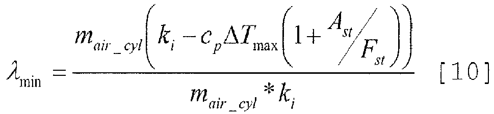

λ min minimum air/fuel ratio that can be obtained in the exhaust gases upstream of thecatalytic converter 11;
cp specific heat of the air;
Δ Tmax maximum temperature difference in the exhaust system;
Ast / Fst stoichiometric ratio of the fuel being used; and
ki lower heating value of the fuel being used. - In order to control the temperature of the exhaust gases through the measurement of the air/fuel ratio of the exhaust gases upstream of the
catalytic converter 11 when the superchargedinternal combustion engine 1 operates in the "scavenging" operating mode (i.e. when there is a significant passage of air from theintake manifold 4 directly into theexhaust pipe 10 of the internal combustion engine 1), theelectronic control unit 22 is designed to learn the value of the air/fuel ratio λmeas of the exhaust gases upstream of thecatalytic converter 11 provided by thesensor 25 and to compare it with a reference value of the air/fuel ratio λtarget of the exhaust gases upstream of thecatalytic converter 11. In particular, theelectronic control unit 22 is designed to calculate the difference between the value of the air/fuel ratio λmeas of the exhaust gases upstream of thecatalytic converter 11 provided by thesensor 25 and the reference value of the air/fuel ratio λtarget of the exhaust gases upstream of thecatalytic converter 11. The reference value of the air/fuel ratio λtarget of the exhaust gases upstream of thecatalytic converter 11 is variable based on the flow rate mair_scav of air that is not involved in the combustion taking place inside thecylinders 3 and flows directly from theintake manifold 4 into theexhaust pipe 10. - The reference value of the air/fuel ratio λtarget is determined based on the operating condition to be taken on by the operation of the
internal combustion engine 1. In particular, the reference value of the air/fuel ratio λtarget is variable based on the engine point and on the thermal state of the internal combustion engine 1 (normally defined starting from the measure of the temperature of the cooling liquid). In particular, theelectronic control unit 22 is designed to exploit as much as possible, in a given condition, the potential enthalpy drop Δh generated by the "scavenging" operating mode so as to favour the turbocharger 12 (in other words, the the reference value of the air/fuel ratio λtarget leans towards the minimum air/fuel ratio λmin) or, alternatively, to heat thecatalytic converter 11 or to restore the oxygen content, for example after an operating step with a basically rich mixture (in other words, the reference value of the air/fuel ratio λtarget is equal to 1 or is basically lean). - After having calculated the difference between the value of the air/fuel ratio λmeas of the exhaust gases upstream of the
catalytic converter 11 provided by thesensor 25 and the reference value of the air/fuel ratio λtarget of the exhaust gases upstream of thecatalytic converter 11, we can determine an air/fuel ratio measure error ελ_scav by applying a filter to the difference between the air/fuel ratio λmeas of the exhaust gases upstream of thecatalytic converter 11 provided by thesensor 25 and the reference value of the air/fuel ratio λtarget of the exhaust gases upstream of thecatalytic converter 11. - Therefore, the air/fuel ratio measure error ελ_scav when the supercharged
internal combustion engine 1 works in the "scavenging" operating mode can be expressed as follows:
ε λ_scav air/fuel ratio measure error when the superchargedinternal combustion engine 1 works in the "scavenging" operating mode;
λ meas value of the air/fuel ratio of the exhaust gases upstream of thecatalytic converter 11 provided by thesensor 25; and
λ target value of the air/fuel ratio of the exhaust gases upstream of thecatalytic converter 11. - In a preliminary adjustment and set up phase, an interval of safety values is defined for the operation of the supercharged
internal combustion engine 1 in the "scavenging" operating mode. In particular, said interval of safety values for the operation of the superchargedinternal combustion engine 1 in the "scavenging" operating mode is defined by an upper threshold value UTVLIMIT_SCAV and by a lower threshold value LTVLIMIT_SCAV. Theelectronic control unit 22 is designed to compare the air/fuel ratio measure error ελ_scav with the interval of safety values for the operation of the superchargedinternal combustion engine 1 in the "scavenging" operating mode, i.e. with the upper threshold value UTVLIMIT_SCAV and with the lower threshold value LTVLIMIT_SCAV. In case the air/fuel ratio measure error ελ_scav lies within the interval of safety values for the operation of the superchargedinternal combustion engine 1 in the "scavenging" operating mode defined by the upper threshold value UTVLIMIT_SCAV and by the lower threshold value LTVLIMIT_SCAV, theelectronic control unit 22 is designed to carry on with the operation of theinternal combustion engine 1 in the "scavenging" operating mode. In case the air/fuel ratio measure error ελ_scav doe not lie within the interval of safety values for the operation of the superchargedinternal combustion engine 1 in the "scavenging" operating mode defined by the upper threshold value UTVLIMIT_SCAV and by the lower threshold value LTVLIMIT_SCAV, theelectronic control unit 22 is designed to limit the operation of theinternal combustion engine 1 in the "scavenging" operating mode. - In other words, the
electronic control unit 22 is designed to limit the flow rate mair_scav of air that is not involved in the combustion taking place inside thecylinders 3 and flows directly from theintake manifold 4 into theexhaust pipe 10, if the air/fuel ratio λmeas of the exhaust gases detected by thesensor 25 does not lie within the interval of safety values defined by the pair of threshold values UTVLIMIT_SCAV, LTVLIMIT_SCAV. - In a preliminary adjustment and set up phase, an interval of inhibition values is defined, outside which the operation of the supercharged
internal combustion engine 1 in the "scavenging" operating mode must be inhibited. In particular, said interval of inhibition values for the operation of the superchargedinternal combustion engine 1 in the "scavenging" operating mode is defined by an upper threshold value UTVINHIB_SCAV and by a lower threshold value LTVINHIB_SCAV. Theelectronic control unit 22 is designed to compare the air/fuel ratio measure error ελ_scav with the interval of inhibition values for the operation of the superchargedinternal combustion engine 1 in the "scavenging" operating mode, i.e. with the upper threshold value UTVINHIB_SCAV and with the lower threshold value LTVINHIB_SCAV. In case the air/fuel ratio measure error ελ_scav lies within the interval of inhibition values for the operation of the superchargedinternal combustion engine 1 in the "scavenging" operating mode defined by the upper threshold value UTVINHIB_SCAV and by the lower threshold value LTVINHIB_SCAV, theelectronic control unit 22 is designed to carry on with the operation of theinternal combustion engine 1 in the "scavenging" operating mode. In case the air/fuel ratio measure error ελ_scav doe not lie within the interval of inhibition values for the operation of the superchargedinternal combustion engine 1 in the "scavenging" operating mode defined by the upper threshold value UTVINHIB_SCAV and by the lower threshold value LTVINHIB_SCAV, theelectronic control unit 22 is designed to stop the operation of theinternal combustion engine 1 in the "scavenging" operating mode. - Clearly, the upper threshold value UTVINHIB_SCAV is greater than the upper threshold value UTVLIMIT_SCAV and the lower threshold value LTVINHIB_SCAV is greater (in absolute value) than the lower threshold value LTVLIMIT_SCAV.
- In other words, the interval of inhibition values, outside which the operation of the supercharged
internal combustion engine 1 in the "scavenging" operating mode must be inhibited, is wider than the interval of safety value, outside which the the operation of the superchargedinternal combustion engine 1 in the "scavenging" operating mode must be limited. - Finally, in a preliminary adjustment and set up phase, an interval of closed-loop values is defined, outside which the air/fuel ratio must be controlled in an open-loop operating mode. In particular, said interval of closed-loop values for the operation of the supercharged
internal combustion engine 1 in the "scavenging" operating mode is defined by an upper threshold value UTVOL_SCAV and by a lower threshold value LTVOL_SCAV. Theelectronic control unit 22 is designed to compare the air/fuel ratio measure error ελ_scav with the interval of closed-loop values for the operation of the superchargedinternal combustion engine 1 in the "scavenging" operating mode, i.e. with the upper threshold value UTVOL_SCAV and with the lower threshold value LTVOL_SCAV. In case the air/fuel ratio measure error ελ_scav lies within the interval of closed loop values defined by the upper threshold value UTVOL_SCAV and by the lower threshold value LTVOL_SCAV, theelectronic control unit 22 is designed to control the air/fuel ratio during the operation of theinternal combustion engine 1 in the "scavenging" operating mode in closed-loop. In case the air/fuel ratio measure error ελ_scav does not lie within the interval of closed loop values defined by the upper threshold value UTVOL_SCAV and by the lower threshold value LTVOL_SCAV, theelectronic control unit 22 is designed to control the air/fuel ratio during the operation of theinternal combustion engine 1 in the "scavenging" operating mode in open-loop. - Typically, the upper threshold value UTVOL_SCAV is smaller both than the upper threshold value UTVINHIB_SCAV and than the upper threshold value UTVLIMIT_SCAV; whereas the lower threshold value LTVOL_SCAV is greater (in absolute value) both than the lower threshold value LTVINHIB_SCAV and then lower threshold value LTVLIMIT_SCAV.
- Furthermore, in order to control the temperature of the exhaust gases through the measurement of the air/fuel ratio of the exhaust gases upstream of the
catalytic converter 11 when the superchargedinternal combustion engine 1 operates in the "scavenging" operating mode (i.e. when there is a significant passage of air from theintake manifold 4 directly into theexhaust pipe 10 of the internal combustion engine 1), theelectronic control unit 22 is designed to carry out a further check on the value of the air/fuel ratio λmeas of the exhaust gases upstream of thecatalytic converter 11 provided by thesensor 25. In particular, theelectronic control unit 22 is configured to filter the value of the air/fuel ratio λmeas of the exhaust gases upstream of thecatalytic converter 11 provided by thesensor 25 and to compare it with the minimum air/fuel ratio λmin that can be obtained in the exhaust gases upstream of thecatalytic converter 11 during the operation of theinternal combustion engine 1 in the scavenging operating mode, as calculated through the equation [11] set forth in the description above. - In case the filtered value of the air/fuel ratio λmeas of the exhaust gases upstream of the
catalytic converter 11 provided by thesensor 25 is greater than the minimum air/fuel ratio λmin that can be obtained in the exhaust gases upstream of thecatalytic converter 11 during the operation of theinternal combustion engine 1, theelectronic control unit 22 is configured to carry on with the operation of theinternal combustion engine 1 in the "scavenging" operating mode. In case the filtered value of the air/fuel ratio λmea of the exhaust gases upstream of thecatalytic converter 11 provided by thesensor 25 is smaller than the minimum air/fuel ratio λmin that can be obtained in the exhaust gases upstream of thecatalytic converter 11 during the operation of theinternal combustion engine 1, theelectronic control unit 22 is configured to limit the operation of theinternal combustion engine 1 in the "scavenging" operating mode. In other words, theelectronic control unit 22 is designed to limit the flow rate mair_scav of air that is not involved in the combustion taking place inside thecylinders 3 and flows directly from theintake manifold 4 into theexhaust pipe 10, if the air/fuel ratio λmeas of the exhaust gases detected by thesensor 25 becomes smaller than the minimum air/fuel ratio λmin. - Finally, the
electronic control unit 22 is configured to carry out a further check on the minimum air/fuel ratio λmin that can be obtained in the exhaust gases upstream of thecatalytic converter 11 during the operation of theinternal combustion engine 1 in the scavenging operating mode, as calculated through the equation [11] set forth in the description above. In particular, theelectronic control unit 22 is designed to compare the minimum air/fuel ratio λmin that can be obtained in the exhaust gases upstream of thecatalytic converter 11 during the operation of theinternal combustion engine 1 in the scavenging operating mode, as calculated through the equation [11] set forth in the description above, with a safety value SV (usually smaller than 1) of the minimum air/fuel ratio λmin that can be obtained in the exhaust gases upstream of thecatalytic converter 11 during the operation of theinternal combustion engine 1, which is calculated in a preliminary adjustment and set up phase and substantially lies in a neighbourhood smaller than 1. - In case the minimum air/fuel ratio λmin that can be obtained in the exhaust gases upstream of the
catalytic converter 11 during the operation of theinternal combustion engine 1 in the scavenging operating mode, as calculated through the equation [11] set forth in the description above, is smaller than the safety value SV of the minimum air/fuel ratio that can be obtained in the exhaust gases upstream of thecatalytic converter 11 during the operation of theinternal combustion engine 1, theelectronic control unit 22 is designed to carry on with the operation of theinternal combustion engine 1 in the "scavenging" operating mode. - In case the minimum air/fuel ratio λmin that can be obtained in the exhaust gases upstream of the
catalytic converter 11 during the operation of theinternal combustion engine 1 in the scavenging operating mode, as calculated through the equation [11] set forth in the description above, is greater than the safety value SV of the minimum air/fuel ratio that can be obtained in the exhaust gases upstream of thecatalytic converter 11 during the operation of theinternal combustion engine 1, theelectronic control unit 22 is designed to stop the operation of theinternal combustion engine 1 in the "scavenging" operating mode. - The method described above to control the temperature of the exhaust gases has some advantages. In particular, it ensures a small computing load for the
electronic control unit 22 and avoids high thermal stresses for the components of the exhaust system during the operation in the "scavenging" operating mode of theinternal combustion engine 1.
Claims (11)
- A method to control the temperature of the exhaust gases of a supercharged internal combustion engine (1) comprising a number of cylinders (3), an intake manifold (4), which is connected to the cylinders (3), an exhaust manifold (5), which is connected to the cylinders (3), as well, and feeds the exhaust gases produced by the combustion taking place inside the cylinders (3) to an exhaust system, and a turbocharger (12), which is provided with a turbine (13) and a supercharger (14); and a sensor (25), which measures the air/fuel ratio of the exhaust gases downstream of the exhaust manifold (5); the supercharged internal combustion engine (1), furthermore, is designed to permit the passage of air not involved in the combustion taking place inside the cylinders (3) from the intake manifold (4) directly into the exhaust pipe (10); the method comprises the steps of:determining the flow rate (mair_scav) of air that is not involved in the combustion taking place inside the cylinders (3) and flows directly from the intake manifold (4) into the exhaust pipe (10);determining the minimum air/fuel ratio (λmin) of the exhaust gases downstream of the exhaust manifold (5) as a function of the flow rate (mair_scav) of air that is not involved in the combustion taking place inside the cylinders (3) and flows directly from the intake manifold (4) into the exhaust pipe (10);detecting the air/fuel ratio (λmeas) of the exhaust gases downstream of the exhaust manifold (5) provided by the sensor (25);comparing the air/fuel ratio (λmeas) of the exhaust gases downstream of the exhaust manifold (5) detected by the sensor (25) and/or the minimum air/fuel ratio (λmin) of the exhaust gases downstream of the exhaust manifold (5) with a number of threshold values (UTVOL_SCAV, UTVINHIB_SCAV, UTVLIMIT_SCAV, LTVOL_SCAV, LTVINHIB_SCAV, LTVLIMIT_SCAV, SV); andcontrolling the supercharged internal combustion engine as a function of the comparison between the air/fuel ratio (λmeas) of the exhaust gases downstream of the exhaust manifold (5) detected by the sensor (25) and/or the minimum air/fuel ratio (λmin) of the exhaust gases downstream of the exhaust manifold (5) with said number of threshold values (UTVOL_SCAV, UTVINHIB_SCAV, UTVLIMIT_SCAV, LTVOL_SCAV, LTVINHIB_SCAV, LTVLIMIT_SCAV, SV) .
- A method according to claim 1 and comprising the further steps of:comparing the air/fuel ratio (λmeas) of the exhaust gases downstream of the exhaust manifold (5) detected by the sensor (25) with a first pair of threshold values (UTVLIMTT_SCAV, LTVLIMIT_SCAV); andlimiting the flow rate (mair_scav) of air that is not involved in the combustion taking place inside the cylinders (3) and flows directly from the intake manifold (4) into the exhaust pipe (10), if the air/fuel ratio (λmeas) of the exhaust gases downstream of the exhaust manifold (5) detected by the sensor (25) is not comprised within the interval defined by the first pair of threshold values (UTVLIMIT_SCAV, LTVLIMIT_SCAV).
- A method according to claim 1 or 2 and comprising the further steps of:comparing the air/fuel ratio (λmeas) of the exhaust gases downstream of the exhaust manifold (5) detected by the sensor (25) with a second pair of threshold values (UTVINHIB_SCAV, LTVINHIB_SCAV); andforbidding the passage of a flow rate (mair_scav) of air that is not involved in the combustion taking place inside the cylinders (3) directly from the intake manifold (4) into the exhaust pipe (10), if the air/fuel ratio (λmeas) of the exhaust gases downstream of the exhaust manifold (5) detected by the sensor (25) is not comprised within the interval defined by the second pair of threshold values (UTVINHIB_SCAV, LTVINHIB_SCAV).
- A method according to claim 2 and 3, wherein the interval defined by the first pair of threshold values (UTVLIMIT_SCAV, LTVLIMIT_SCAV) is comprised within the interval defined by the second pair of threshold values (UTVINHIB_SCAV, LTVINHIB_SCAV).
- A method according to any of the previous claims and comprising the further steps of:comparing the air/fuel ratio (λmeas) of the exhaust gases downstream of the exhaust manifold (5) detected by the sensor (25) with a third pair of threshold values (UTVOL_SCAV, LTVOL_SCAV); andcontrolling the air/fuel ratio of the exhaust gases downstream of the exhaust manifold (5) in open-loop, if the air/fuel ratio (λmeas) of the exhaust gases downstream of the exhaust manifold (5) detected by the sensor (25) is not comprised within the interval defined by the third pair of threshold values (UTVOL_SCAV, LTVOL_SCAV).
- A method according to any of the previous claims and comprising the further steps of:comparing the air/fuel ratio (λmeas) of the exhaust gases downstream of the exhaust manifold (5) detected by the sensor (25) with the minimum air/fuel ratio (λmin) of the exhaust gases downstream of the exhaust manifold (5); andlimiting the flow rate (mair_scav) of air that is not involved in the combustion taking place inside the cylinders (3) and flows directly from the intake manifold (4) into the exhaust pipe (10), if the air/fuel ratio (λmeas) of the exhaust gases downstream of the exhaust manifold (5) detected by the sensor (25) is smaller than the minimum air/fuel ratio (λmin) of the exhaust gases downstream of the exhaust manifold (5).
- A method according to any of the previous claims and comprising the further steps of:comparing the minimum air/fuel ratio (λmin) of the exhaust gases downstream of the exhaust manifold (5) with a safety value (SV); andforbidding the passage of a flow rate (mair_scav) of air that is not involved in the combustion taking place inside the cylinders (3) directly from the intake manifold (4) into the exhaust pipe (10), if the minimum air/fuel ratio (λmin) of the exhaust gases downstream of the exhaust manifold (5) is greater than the safety value (SV).
- A method according to any of the previous claims and comprising the further steps of:determining the reference value of the air/fuel ratio (λtarget) of the exhaust gases as a function of the flow rate (mair_scav) of air that is not involved in the combustion taking place inside the cylinders (3) and flows directly from the intake manifold (4) into the exhaust pipe (10);calculating the difference between the air/fuel ratio (λmeas) of the exhaust gases downstream of the exhaust manifold (5) detected by the sensor (25) and the reference value of the air/fuel ratio (λtarget) of the exhaust gases; andcontrolling the supercharged internal combustion engine (1) as a function of the difference between the air/fuel ratio (λmeas) of the exhaust gases downstream of the exhaust manifold (5) detected by the sensor (25) and the reference value of the air/fuel ratio (λtarget) of the exhaust gases.
- A method according to claim 8, wherein the reference value of the air/fuel ratio (λtarget) is variable as a function of the engine point and of the thermal state of the internal combustion engine (1).
- A method according to claim 8 or 9 and comprising the further step of filtering the difference between the air/fuel ratio (λmeas) of the exhaust gases downstream of the exhaust manifold (5) detected by the sensor (25) and the reference value of the air/fuel ratio (λtarget) of the exhaust gases.
- A method according to any of the previous claims, wherein the minimum air/fuel ratio (λmin) of the exhaust gases downstream of the exhaust manifold (5) is calculated by means of the formula:

λ min air/fuel ratio that can be obtained in the exhaust gases downstream of the exhaust manifold (5);;
cp specific heat of the air;
Δ Tmax maximum temperature difference in an exhaust system;
ki lower heating value of the fuel being used; and Ast / Fst stoichiometric ratio of the fuel being used.
Applications Claiming Priority (1)
| Application Number | Priority Date | Filing Date | Title |
|---|---|---|---|
| ITBO20140676 | 2014-12-02 |
Publications (2)
| Publication Number | Publication Date |
|---|---|
| EP3040543A1 true EP3040543A1 (en) | 2016-07-06 |
| EP3040543B1 EP3040543B1 (en) | 2017-11-29 |
Family
ID=52232265
Family Applications (1)
| Application Number | Title | Priority Date | Filing Date |
|---|---|---|---|
| EP15197676.8A Active EP3040543B1 (en) | 2014-12-02 | 2015-12-02 | Method to control the temperature of the exhaust gases of a supercharged internal combustion engine |
Country Status (2)
| Country | Link |
|---|---|
| US (1) | US9567886B2 (en) |
| EP (1) | EP3040543B1 (en) |
Cited By (1)
| Publication number | Priority date | Publication date | Assignee | Title |
|---|---|---|---|---|
| CN110925107A (en) * | 2019-12-20 | 2020-03-27 | 潍柴西港新能源动力有限公司 | Fuel closed-loop control method for gas power generation engine |
Families Citing this family (3)
| Publication number | Priority date | Publication date | Assignee | Title |
|---|---|---|---|---|
| JP6337819B2 (en) * | 2015-03-30 | 2018-06-06 | トヨタ自動車株式会社 | Internal combustion engine |
| JP6319254B2 (en) * | 2015-09-29 | 2018-05-09 | マツダ株式会社 | Engine control device |
| US10233854B1 (en) * | 2017-11-07 | 2019-03-19 | Fca Us Llc | Engine control systems and methods for regulating emissions during scavenging |
Citations (4)
| Publication number | Priority date | Publication date | Assignee | Title |
|---|---|---|---|---|
| DE102004038389A1 (en) * | 2004-08-06 | 2006-03-16 | Iav Gmbh Ingenieurgesellschaft Auto Und Verkehr | Method for calculating the air ratio in the combustion chamber of an internal combustion engine comprises forming a model for the connection between a calculated value for the air ratio and the measured value |
| US20090070009A1 (en) * | 2007-09-12 | 2009-03-12 | Matthias Delp | Method for determining the trapping efficiency and/or a scavenging air mass of an internal combustion engine |
| EP2669497A1 (en) * | 2011-01-24 | 2013-12-04 | Toyota Jidosha Kabushiki Kaisha | Control device for supercharger-equipped internal combustion engine |
| EP2674595A1 (en) * | 2011-02-07 | 2013-12-18 | Nissan Motor Co., Ltd | Control device for internal combustion engine equipped with turbocharger |
Family Cites Families (5)
| Publication number | Priority date | Publication date | Assignee | Title |
|---|---|---|---|---|
| US6293097B1 (en) * | 1999-08-16 | 2001-09-25 | Ford Global Technologies, Inc. | On-board reductant delivery system |
| DE10005888A1 (en) * | 2000-02-10 | 2001-08-16 | Mann & Hummel Filter | Method and device for simultaneous adjustment of an air intake flow for an internal combustion engine and a secondary airflow into the same internal combustion engine's exhaust gas unit creates the secondary airflow by a fan. |
| DE10348131A1 (en) * | 2003-10-16 | 2005-05-12 | Daimler Chrysler Ag | Internal combustion engine with exhaust gas turbocharger and secondary air injection, as well as diagnosis and control of secondary air injection |
| JP2008261287A (en) * | 2007-04-12 | 2008-10-30 | Fuji Heavy Ind Ltd | Filter clogging judgment device for diesel engine |
| US8359839B2 (en) * | 2009-09-29 | 2013-01-29 | Ford Global Technologies, Llc | System and method for regenerating a particulate filter for a direct injection engine |
-
2015
- 2015-11-30 US US14/954,219 patent/US9567886B2/en active Active - Reinstated
- 2015-12-02 EP EP15197676.8A patent/EP3040543B1/en active Active
Patent Citations (4)
| Publication number | Priority date | Publication date | Assignee | Title |
|---|---|---|---|---|
| DE102004038389A1 (en) * | 2004-08-06 | 2006-03-16 | Iav Gmbh Ingenieurgesellschaft Auto Und Verkehr | Method for calculating the air ratio in the combustion chamber of an internal combustion engine comprises forming a model for the connection between a calculated value for the air ratio and the measured value |
| US20090070009A1 (en) * | 2007-09-12 | 2009-03-12 | Matthias Delp | Method for determining the trapping efficiency and/or a scavenging air mass of an internal combustion engine |
| EP2669497A1 (en) * | 2011-01-24 | 2013-12-04 | Toyota Jidosha Kabushiki Kaisha | Control device for supercharger-equipped internal combustion engine |
| EP2674595A1 (en) * | 2011-02-07 | 2013-12-18 | Nissan Motor Co., Ltd | Control device for internal combustion engine equipped with turbocharger |
Cited By (2)
| Publication number | Priority date | Publication date | Assignee | Title |
|---|---|---|---|---|
| CN110925107A (en) * | 2019-12-20 | 2020-03-27 | 潍柴西港新能源动力有限公司 | Fuel closed-loop control method for gas power generation engine |
| CN110925107B (en) * | 2019-12-20 | 2022-02-22 | 潍柴西港新能源动力有限公司 | Fuel closed-loop control method for gas power generation engine |
Also Published As
| Publication number | Publication date |
|---|---|
| US9567886B2 (en) | 2017-02-14 |
| EP3040543B1 (en) | 2017-11-29 |
| US20160153331A1 (en) | 2016-06-02 |
Similar Documents
| Publication | Publication Date | Title |
|---|---|---|
| EP2198141B1 (en) | Exhaust-gas recirculation apparatus and exhaust-gas recirculation flow rate estimation method for internal combustion engines | |
| JP5905066B1 (en) | Control device and control method for internal combustion engine | |
| US8453434B2 (en) | Method for adapting an SCR catalytic converter in an exhaust system of a motor vehicle | |
| JP5907339B2 (en) | In-cylinder inflow EGR gas flow rate estimation device for internal combustion engine | |
| JP5115629B2 (en) | Control device for internal combustion engine | |
| CN106285981B (en) | An EGR flow calculation method based on valve body and intake pressure sensor | |
| EP2098710A1 (en) | A method for estimating the oxygen concentration in internal combustion engines | |
| JP6653274B2 (en) | Failure diagnosis device for low pressure EGR system | |
| JP4715799B2 (en) | Exhaust gas recirculation device for internal combustion engine | |
| US9322349B2 (en) | Internal combustion engine control apparatus | |
| EP3029307B1 (en) | Control device for internal combustion engine | |
| JP4192759B2 (en) | Injection quantity control device for diesel engine | |
| US9464585B2 (en) | Exhaust gas recirculation control system of engine | |
| EP3040543B1 (en) | Method to control the temperature of the exhaust gases of a supercharged internal combustion engine | |
| CN104948322A (en) | Control device of internal combustion engine | |
| WO2006000472A1 (en) | Method for controlling a supercharged internal combustion engine | |
| EP3128159B1 (en) | Method to control a low-pressure exhaust gas recirculation egr circuit in an internal combustion engine | |
| US20190153967A1 (en) | Method for controlling engine | |
| EP3707362B1 (en) | Engine control systems and methods for regulating emissions during scavenging | |
| EP3128158B1 (en) | Method to control a low-pressure exhaust gas recirculation egr circuit in an internal combustion engine | |
| EP3640461B1 (en) | Estimation method to determine the concentration of recirculated exhaust gas present in a cylinder of an internal combustion engine | |
| JP6498537B2 (en) | Control device for internal combustion engine | |
| US7469687B2 (en) | Method and device for operating an internal combustion engine | |
| JP6824712B2 (en) | Fuel injection control device and fuel injection control method | |
| JP5857678B2 (en) | Control device for internal combustion engine and control method for internal combustion engine |
Legal Events
| Date | Code | Title | Description |
|---|---|---|---|
| PUAI | Public reference made under article 153(3) epc to a published international application that has entered the european phase |
Free format text: ORIGINAL CODE: 0009012 |
|
| AK | Designated contracting states |
Kind code of ref document: A1 Designated state(s): AL AT BE BG CH CY CZ DE DK EE ES FI FR GB GR HR HU IE IS IT LI LT LU LV MC MK MT NL NO PL PT RO RS SE SI SK SM TR |
|
| AX | Request for extension of the european patent |
Extension state: BA ME |
|
| 17P | Request for examination filed |
Effective date: 20161230 |
|
| GRAP | Despatch of communication of intention to grant a patent |
Free format text: ORIGINAL CODE: EPIDOSNIGR1 |
|
| INTG | Intention to grant announced |
Effective date: 20170616 |
|
| GRAS | Grant fee paid |
Free format text: ORIGINAL CODE: EPIDOSNIGR3 |
|
| GRAA | (expected) grant |
Free format text: ORIGINAL CODE: 0009210 |
|
| AK | Designated contracting states |
Kind code of ref document: B1 Designated state(s): AL AT BE BG CH CY CZ DE DK EE ES FI FR GB GR HR HU IE IS IT LI LT LU LV MC MK MT NL NO PL PT RO RS SE SI SK SM TR |
|
| REG | Reference to a national code |
Ref country code: CH Ref legal event code: EP |
|
| REG | Reference to a national code |
Ref country code: AT Ref legal event code: REF Ref document number: 950624 Country of ref document: AT Kind code of ref document: T Effective date: 20171215 |
|
| REG | Reference to a national code |
Ref country code: FR Ref legal event code: PLFP Year of fee payment: 3 |
|
| REG | Reference to a national code |
Ref country code: IE Ref legal event code: FG4D |
|
| REG | Reference to a national code |
Ref country code: DE Ref legal event code: R096 Ref document number: 602015006323 Country of ref document: DE |
|
| REG | Reference to a national code |
Ref country code: NL Ref legal event code: MP Effective date: 20171129 |
|
| REG | Reference to a national code |
Ref country code: LT Ref legal event code: MG4D |
|
| REG | Reference to a national code |
Ref country code: AT Ref legal event code: MK05 Ref document number: 950624 Country of ref document: AT Kind code of ref document: T Effective date: 20171129 |
|
| PG25 | Lapsed in a contracting state [announced via postgrant information from national office to epo] |
Ref country code: SE Free format text: LAPSE BECAUSE OF FAILURE TO SUBMIT A TRANSLATION OF THE DESCRIPTION OR TO PAY THE FEE WITHIN THE PRESCRIBED TIME-LIMIT Effective date: 20171129 Ref country code: LT Free format text: LAPSE BECAUSE OF FAILURE TO SUBMIT A TRANSLATION OF THE DESCRIPTION OR TO PAY THE FEE WITHIN THE PRESCRIBED TIME-LIMIT Effective date: 20171129 Ref country code: FI Free format text: LAPSE BECAUSE OF FAILURE TO SUBMIT A TRANSLATION OF THE DESCRIPTION OR TO PAY THE FEE WITHIN THE PRESCRIBED TIME-LIMIT Effective date: 20171129 Ref country code: NO Free format text: LAPSE BECAUSE OF FAILURE TO SUBMIT A TRANSLATION OF THE DESCRIPTION OR TO PAY THE FEE WITHIN THE PRESCRIBED TIME-LIMIT Effective date: 20180228 Ref country code: ES Free format text: LAPSE BECAUSE OF FAILURE TO SUBMIT A TRANSLATION OF THE DESCRIPTION OR TO PAY THE FEE WITHIN THE PRESCRIBED TIME-LIMIT Effective date: 20171129 |
|
| PG25 | Lapsed in a contracting state [announced via postgrant information from national office to epo] |
Ref country code: AT Free format text: LAPSE BECAUSE OF FAILURE TO SUBMIT A TRANSLATION OF THE DESCRIPTION OR TO PAY THE FEE WITHIN THE PRESCRIBED TIME-LIMIT Effective date: 20171129 Ref country code: BG Free format text: LAPSE BECAUSE OF FAILURE TO SUBMIT A TRANSLATION OF THE DESCRIPTION OR TO PAY THE FEE WITHIN THE PRESCRIBED TIME-LIMIT Effective date: 20180228 Ref country code: RS Free format text: LAPSE BECAUSE OF FAILURE TO SUBMIT A TRANSLATION OF THE DESCRIPTION OR TO PAY THE FEE WITHIN THE PRESCRIBED TIME-LIMIT Effective date: 20171129 Ref country code: LV Free format text: LAPSE BECAUSE OF FAILURE TO SUBMIT A TRANSLATION OF THE DESCRIPTION OR TO PAY THE FEE WITHIN THE PRESCRIBED TIME-LIMIT Effective date: 20171129 Ref country code: GR Free format text: LAPSE BECAUSE OF FAILURE TO SUBMIT A TRANSLATION OF THE DESCRIPTION OR TO PAY THE FEE WITHIN THE PRESCRIBED TIME-LIMIT Effective date: 20180301 Ref country code: HR Free format text: LAPSE BECAUSE OF FAILURE TO SUBMIT A TRANSLATION OF THE DESCRIPTION OR TO PAY THE FEE WITHIN THE PRESCRIBED TIME-LIMIT Effective date: 20171129 |
|
| PG25 | Lapsed in a contracting state [announced via postgrant information from national office to epo] |
Ref country code: NL Free format text: LAPSE BECAUSE OF FAILURE TO SUBMIT A TRANSLATION OF THE DESCRIPTION OR TO PAY THE FEE WITHIN THE PRESCRIBED TIME-LIMIT Effective date: 20171129 |
|
| PG25 | Lapsed in a contracting state [announced via postgrant information from national office to epo] |
Ref country code: SK Free format text: LAPSE BECAUSE OF FAILURE TO SUBMIT A TRANSLATION OF THE DESCRIPTION OR TO PAY THE FEE WITHIN THE PRESCRIBED TIME-LIMIT Effective date: 20171129 Ref country code: DK Free format text: LAPSE BECAUSE OF FAILURE TO SUBMIT A TRANSLATION OF THE DESCRIPTION OR TO PAY THE FEE WITHIN THE PRESCRIBED TIME-LIMIT Effective date: 20171129 Ref country code: CY Free format text: LAPSE BECAUSE OF FAILURE TO SUBMIT A TRANSLATION OF THE DESCRIPTION OR TO PAY THE FEE WITHIN THE PRESCRIBED TIME-LIMIT Effective date: 20171129 Ref country code: EE Free format text: LAPSE BECAUSE OF FAILURE TO SUBMIT A TRANSLATION OF THE DESCRIPTION OR TO PAY THE FEE WITHIN THE PRESCRIBED TIME-LIMIT Effective date: 20171129 Ref country code: CZ Free format text: LAPSE BECAUSE OF FAILURE TO SUBMIT A TRANSLATION OF THE DESCRIPTION OR TO PAY THE FEE WITHIN THE PRESCRIBED TIME-LIMIT Effective date: 20171129 |
|
| REG | Reference to a national code |
Ref country code: DE Ref legal event code: R097 Ref document number: 602015006323 Country of ref document: DE |
|
| PG25 | Lapsed in a contracting state [announced via postgrant information from national office to epo] |
Ref country code: PL Free format text: LAPSE BECAUSE OF FAILURE TO SUBMIT A TRANSLATION OF THE DESCRIPTION OR TO PAY THE FEE WITHIN THE PRESCRIBED TIME-LIMIT Effective date: 20171129 Ref country code: SM Free format text: LAPSE BECAUSE OF FAILURE TO SUBMIT A TRANSLATION OF THE DESCRIPTION OR TO PAY THE FEE WITHIN THE PRESCRIBED TIME-LIMIT Effective date: 20171129 Ref country code: RO Free format text: LAPSE BECAUSE OF FAILURE TO SUBMIT A TRANSLATION OF THE DESCRIPTION OR TO PAY THE FEE WITHIN THE PRESCRIBED TIME-LIMIT Effective date: 20171129 |
|
| REG | Reference to a national code |
Ref country code: IE Ref legal event code: MM4A |
|
| PG25 | Lapsed in a contracting state [announced via postgrant information from national office to epo] |
Ref country code: LU Free format text: LAPSE BECAUSE OF NON-PAYMENT OF DUE FEES Effective date: 20171202 Ref country code: MT Free format text: LAPSE BECAUSE OF NON-PAYMENT OF DUE FEES Effective date: 20171202 |
|
| PLBE | No opposition filed within time limit |
Free format text: ORIGINAL CODE: 0009261 |
|
| STAA | Information on the status of an ep patent application or granted ep patent |
Free format text: STATUS: NO OPPOSITION FILED WITHIN TIME LIMIT |
|
| REG | Reference to a national code |
Ref country code: BE Ref legal event code: MM Effective date: 20171231 |
|
| PG25 | Lapsed in a contracting state [announced via postgrant information from national office to epo] |
Ref country code: IE Free format text: LAPSE BECAUSE OF NON-PAYMENT OF DUE FEES Effective date: 20171202 |
|
| 26N | No opposition filed |
Effective date: 20180830 |
|
| PG25 | Lapsed in a contracting state [announced via postgrant information from national office to epo] |
Ref country code: SI Free format text: LAPSE BECAUSE OF FAILURE TO SUBMIT A TRANSLATION OF THE DESCRIPTION OR TO PAY THE FEE WITHIN THE PRESCRIBED TIME-LIMIT Effective date: 20171129 Ref country code: BE Free format text: LAPSE BECAUSE OF NON-PAYMENT OF DUE FEES Effective date: 20171231 |
|
| PG25 | Lapsed in a contracting state [announced via postgrant information from national office to epo] |
Ref country code: MC Free format text: LAPSE BECAUSE OF FAILURE TO SUBMIT A TRANSLATION OF THE DESCRIPTION OR TO PAY THE FEE WITHIN THE PRESCRIBED TIME-LIMIT Effective date: 20171129 Ref country code: HU Free format text: LAPSE BECAUSE OF FAILURE TO SUBMIT A TRANSLATION OF THE DESCRIPTION OR TO PAY THE FEE WITHIN THE PRESCRIBED TIME-LIMIT; INVALID AB INITIO Effective date: 20151202 |
|
| REG | Reference to a national code |
Ref country code: CH Ref legal event code: PL |
|
| PG25 | Lapsed in a contracting state [announced via postgrant information from national office to epo] |
Ref country code: MK Free format text: LAPSE BECAUSE OF FAILURE TO SUBMIT A TRANSLATION OF THE DESCRIPTION OR TO PAY THE FEE WITHIN THE PRESCRIBED TIME-LIMIT Effective date: 20171129 |
|
| PG25 | Lapsed in a contracting state [announced via postgrant information from national office to epo] |
Ref country code: CH Free format text: LAPSE BECAUSE OF NON-PAYMENT OF DUE FEES Effective date: 20181231 Ref country code: LI Free format text: LAPSE BECAUSE OF NON-PAYMENT OF DUE FEES Effective date: 20181231 |
|
| PG25 | Lapsed in a contracting state [announced via postgrant information from national office to epo] |
Ref country code: TR Free format text: LAPSE BECAUSE OF FAILURE TO SUBMIT A TRANSLATION OF THE DESCRIPTION OR TO PAY THE FEE WITHIN THE PRESCRIBED TIME-LIMIT Effective date: 20171129 |
|
| PG25 | Lapsed in a contracting state [announced via postgrant information from national office to epo] |
Ref country code: PT Free format text: LAPSE BECAUSE OF FAILURE TO SUBMIT A TRANSLATION OF THE DESCRIPTION OR TO PAY THE FEE WITHIN THE PRESCRIBED TIME-LIMIT Effective date: 20171129 |
|
| PG25 | Lapsed in a contracting state [announced via postgrant information from national office to epo] |
Ref country code: AL Free format text: LAPSE BECAUSE OF FAILURE TO SUBMIT A TRANSLATION OF THE DESCRIPTION OR TO PAY THE FEE WITHIN THE PRESCRIBED TIME-LIMIT Effective date: 20171129 Ref country code: IS Free format text: LAPSE BECAUSE OF FAILURE TO SUBMIT A TRANSLATION OF THE DESCRIPTION OR TO PAY THE FEE WITHIN THE PRESCRIBED TIME-LIMIT Effective date: 20180329 |
|
| GBPC | Gb: european patent ceased through non-payment of renewal fee |
Effective date: 20191202 |
|
| PG25 | Lapsed in a contracting state [announced via postgrant information from national office to epo] |
Ref country code: GB Free format text: LAPSE BECAUSE OF NON-PAYMENT OF DUE FEES Effective date: 20191202 |
|
| PGFP | Annual fee paid to national office [announced via postgrant information from national office to epo] |
Ref country code: DE Payment date: 20251126 Year of fee payment: 11 |
|
| PGFP | Annual fee paid to national office [announced via postgrant information from national office to epo] |
Ref country code: IT Payment date: 20251119 Year of fee payment: 11 |
|
| PGFP | Annual fee paid to national office [announced via postgrant information from national office to epo] |
Ref country code: FR Payment date: 20251120 Year of fee payment: 11 |