EP3040540A1 - Methods and systems to characterize noises sensed by a knock sensor - Google Patents
Methods and systems to characterize noises sensed by a knock sensor Download PDFInfo
- Publication number
- EP3040540A1 EP3040540A1 EP15201539.2A EP15201539A EP3040540A1 EP 3040540 A1 EP3040540 A1 EP 3040540A1 EP 15201539 A EP15201539 A EP 15201539A EP 3040540 A1 EP3040540 A1 EP 3040540A1
- Authority
- EP
- European Patent Office
- Prior art keywords
- noise signal
- preconditioned
- noise
- signal
- ecu
- Prior art date
- Legal status (The legal status is an assumption and is not a legal conclusion. Google has not performed a legal analysis and makes no representation as to the accuracy of the status listed.)
- Granted
Links
- 238000000034 method Methods 0.000 title claims abstract description 45
- 238000004458 analytical method Methods 0.000 claims description 10
- 238000012512 characterization method Methods 0.000 claims description 6
- 235000009413 Ratibida columnifera Nutrition 0.000 claims description 3
- 241000510442 Ratibida peduncularis Species 0.000 claims description 3
- 238000004590 computer program Methods 0.000 claims 4
- 238000002485 combustion reaction Methods 0.000 description 24
- 239000000446 fuel Substances 0.000 description 17
- 239000007789 gas Substances 0.000 description 6
- 239000000203 mixture Substances 0.000 description 6
- 230000002159 abnormal effect Effects 0.000 description 5
- 239000007800 oxidant agent Substances 0.000 description 5
- 238000007906 compression Methods 0.000 description 4
- 239000000284 extract Substances 0.000 description 4
- VNWKTOKETHGBQD-UHFFFAOYSA-N methane Chemical compound C VNWKTOKETHGBQD-UHFFFAOYSA-N 0.000 description 4
- 230000001590 oxidative effect Effects 0.000 description 4
- 238000012545 processing Methods 0.000 description 4
- 239000013598 vector Substances 0.000 description 4
- QVGXLLKOCUKJST-UHFFFAOYSA-N atomic oxygen Chemical compound [O] QVGXLLKOCUKJST-UHFFFAOYSA-N 0.000 description 3
- 239000001301 oxygen Substances 0.000 description 3
- 229910052760 oxygen Inorganic materials 0.000 description 3
- 230000010363 phase shift Effects 0.000 description 3
- 238000010248 power generation Methods 0.000 description 3
- 230000003595 spectral effect Effects 0.000 description 3
- ATUOYWHBWRKTHZ-UHFFFAOYSA-N Propane Chemical compound CCC ATUOYWHBWRKTHZ-UHFFFAOYSA-N 0.000 description 2
- 230000001133 acceleration Effects 0.000 description 2
- 230000008901 benefit Effects 0.000 description 2
- 230000006835 compression Effects 0.000 description 2
- 238000013480 data collection Methods 0.000 description 2
- 230000007423 decrease Effects 0.000 description 2
- 238000013461 design Methods 0.000 description 2
- 238000011161 development Methods 0.000 description 2
- 238000010586 diagram Methods 0.000 description 2
- 230000000694 effects Effects 0.000 description 2
- 238000004519 manufacturing process Methods 0.000 description 2
- 239000003345 natural gas Substances 0.000 description 2
- 238000010223 real-time analysis Methods 0.000 description 2
- 230000005355 Hall effect Effects 0.000 description 1
- 239000003570 air Substances 0.000 description 1
- 230000009286 beneficial effect Effects 0.000 description 1
- -1 biogas Substances 0.000 description 1
- 239000003245 coal Substances 0.000 description 1
- 239000000567 combustion gas Substances 0.000 description 1
- 238000004891 communication Methods 0.000 description 1
- 238000005474 detonation Methods 0.000 description 1
- 238000007599 discharging Methods 0.000 description 1
- 239000012530 fluid Substances 0.000 description 1
- 239000003502 gasoline Substances 0.000 description 1
- 238000002347 injection Methods 0.000 description 1
- 239000007924 injection Substances 0.000 description 1
- 239000007788 liquid Substances 0.000 description 1
- 238000012423 maintenance Methods 0.000 description 1
- 238000013507 mapping Methods 0.000 description 1
- 238000005259 measurement Methods 0.000 description 1
- 230000003278 mimic effect Effects 0.000 description 1
- 238000012544 monitoring process Methods 0.000 description 1
- 230000010355 oscillation Effects 0.000 description 1
- 239000003209 petroleum derivative Substances 0.000 description 1
- 239000001294 propane Substances 0.000 description 1
- 239000010865 sewage Substances 0.000 description 1
Images


Classifications
-
- G—PHYSICS
- G01—MEASURING; TESTING
- G01L—MEASURING FORCE, STRESS, TORQUE, WORK, MECHANICAL POWER, MECHANICAL EFFICIENCY, OR FLUID PRESSURE
- G01L23/00—Devices or apparatus for measuring or indicating or recording rapid changes, such as oscillations, in the pressure of steam, gas, or liquid; Indicators for determining work or energy of steam, internal-combustion, or other fluid-pressure engines from the condition of the working fluid
- G01L23/22—Devices or apparatus for measuring or indicating or recording rapid changes, such as oscillations, in the pressure of steam, gas, or liquid; Indicators for determining work or energy of steam, internal-combustion, or other fluid-pressure engines from the condition of the working fluid for detecting or indicating knocks in internal-combustion engines; Units comprising pressure-sensitive members combined with ignitors for firing internal-combustion engines
- G01L23/221—Devices or apparatus for measuring or indicating or recording rapid changes, such as oscillations, in the pressure of steam, gas, or liquid; Indicators for determining work or energy of steam, internal-combustion, or other fluid-pressure engines from the condition of the working fluid for detecting or indicating knocks in internal-combustion engines; Units comprising pressure-sensitive members combined with ignitors for firing internal-combustion engines for detecting or indicating knocks in internal combustion engines
-
- G—PHYSICS
- G01—MEASURING; TESTING
- G01H—MEASUREMENT OF MECHANICAL VIBRATIONS OR ULTRASONIC, SONIC OR INFRASONIC WAVES
- G01H17/00—Measuring mechanical vibrations or ultrasonic, sonic or infrasonic waves, not provided for in the preceding groups
-
- G—PHYSICS
- G01—MEASURING; TESTING
- G01L—MEASURING FORCE, STRESS, TORQUE, WORK, MECHANICAL POWER, MECHANICAL EFFICIENCY, OR FLUID PRESSURE
- G01L23/00—Devices or apparatus for measuring or indicating or recording rapid changes, such as oscillations, in the pressure of steam, gas, or liquid; Indicators for determining work or energy of steam, internal-combustion, or other fluid-pressure engines from the condition of the working fluid
- G01L23/22—Devices or apparatus for measuring or indicating or recording rapid changes, such as oscillations, in the pressure of steam, gas, or liquid; Indicators for determining work or energy of steam, internal-combustion, or other fluid-pressure engines from the condition of the working fluid for detecting or indicating knocks in internal-combustion engines; Units comprising pressure-sensitive members combined with ignitors for firing internal-combustion engines
- G01L23/221—Devices or apparatus for measuring or indicating or recording rapid changes, such as oscillations, in the pressure of steam, gas, or liquid; Indicators for determining work or energy of steam, internal-combustion, or other fluid-pressure engines from the condition of the working fluid for detecting or indicating knocks in internal-combustion engines; Units comprising pressure-sensitive members combined with ignitors for firing internal-combustion engines for detecting or indicating knocks in internal combustion engines
- G01L23/225—Devices or apparatus for measuring or indicating or recording rapid changes, such as oscillations, in the pressure of steam, gas, or liquid; Indicators for determining work or energy of steam, internal-combustion, or other fluid-pressure engines from the condition of the working fluid for detecting or indicating knocks in internal-combustion engines; Units comprising pressure-sensitive members combined with ignitors for firing internal-combustion engines for detecting or indicating knocks in internal combustion engines circuit arrangements therefor
-
- F—MECHANICAL ENGINEERING; LIGHTING; HEATING; WEAPONS; BLASTING
- F02—COMBUSTION ENGINES; HOT-GAS OR COMBUSTION-PRODUCT ENGINE PLANTS
- F02D—CONTROLLING COMBUSTION ENGINES
- F02D35/00—Controlling engines, dependent on conditions exterior or interior to engines, not otherwise provided for
- F02D35/02—Controlling engines, dependent on conditions exterior or interior to engines, not otherwise provided for on interior conditions
- F02D35/027—Controlling engines, dependent on conditions exterior or interior to engines, not otherwise provided for on interior conditions using knock sensors
-
- G—PHYSICS
- G01—MEASURING; TESTING
- G01L—MEASURING FORCE, STRESS, TORQUE, WORK, MECHANICAL POWER, MECHANICAL EFFICIENCY, OR FLUID PRESSURE
- G01L23/00—Devices or apparatus for measuring or indicating or recording rapid changes, such as oscillations, in the pressure of steam, gas, or liquid; Indicators for determining work or energy of steam, internal-combustion, or other fluid-pressure engines from the condition of the working fluid
- G01L23/22—Devices or apparatus for measuring or indicating or recording rapid changes, such as oscillations, in the pressure of steam, gas, or liquid; Indicators for determining work or energy of steam, internal-combustion, or other fluid-pressure engines from the condition of the working fluid for detecting or indicating knocks in internal-combustion engines; Units comprising pressure-sensitive members combined with ignitors for firing internal-combustion engines
-
- F—MECHANICAL ENGINEERING; LIGHTING; HEATING; WEAPONS; BLASTING
- F02—COMBUSTION ENGINES; HOT-GAS OR COMBUSTION-PRODUCT ENGINE PLANTS
- F02D—CONTROLLING COMBUSTION ENGINES
- F02D41/00—Electrical control of supply of combustible mixture or its constituents
- F02D41/02—Circuit arrangements for generating control signals
- F02D41/14—Introducing closed-loop corrections
- F02D41/1401—Introducing closed-loop corrections characterised by the control or regulation method
- F02D2041/1413—Controller structures or design
- F02D2041/1432—Controller structures or design the system including a filter, e.g. a low pass or high pass filter
-
- F—MECHANICAL ENGINEERING; LIGHTING; HEATING; WEAPONS; BLASTING
- F02—COMBUSTION ENGINES; HOT-GAS OR COMBUSTION-PRODUCT ENGINE PLANTS
- F02D—CONTROLLING COMBUSTION ENGINES
- F02D2200/00—Input parameters for engine control
- F02D2200/02—Input parameters for engine control the parameters being related to the engine
- F02D2200/025—Engine noise, e.g. determined by using an acoustic sensor
Definitions
- the subject matter disclosed herein relates to knock sensors, and more specifically, to knock sensors suitable for characterizing certain noise.
- Combustion engines typically combust a carbonaceous fuel, such as natural gas, gasoline, diesel, and the like, and use the corresponding expansion of high temperature and pressure gases to apply a force to certain components of the engine, e.g., piston disposed in a cylinder, to move the components over a distance.
- a carbonaceous fuel such as natural gas, gasoline, diesel, and the like
- Each cylinder may include one or more valves that open and close correlative with combustion of the carbonaceous fuel.
- an intake valve may direct an oxidizer such as air into the cylinder, which is then mixed with fuel and combusted.
- Combustion fluids e.g., hot gases, may then be directed to exit the cylinder via an exhaust valve.
- the carbonaceous fuel is transformed into mechanical motion, useful in driving a load.
- the load may be a generator that produces electric power.
- Knock sensors can be used to monitor multi-cylinder combustion engines.
- a knock sensor can be mounted to the exterior of an engine cylinder and used to determine whether or not the engine is running as desired. Sometimes a knock sensor detects a noise that may not be identifiable at the time. It would be desirable to have a way to characterize the noise.
- a method of characterizing a noise signal includes receiving a noise signal sensed by a knock sensor coupled to a reciprocating device, preconditioning the noise signal to derive a preconditioned noise signal, applying an ADSR envelope to the preconditioned noise signal, extracting tonal information from the preconditioned noise signal, and creating a fingerprint of the noise signal based on the ADSR envelope, the tonal information, or a combination thereof
- a system in a second embodiment, includes a controller configured to control a reciprocating device.
- the controller has a processor configured to receive a noise signal sensed by a knock sensor coupled to a reciprocating device, precondition the noise signal to derive a preconditioned noise signal, apply an ADSR envelope to the preconditioned noise signal, extract tonal information from the preconditioned noise signal, and create a fingerprint of the noise signal based on the ADSR envelope, the tonal information, or a combination thereof.
- a non-transitory computer readable medium includes executable instructions that when executed cause a processor to receive, from a knock sensor coupled to a reciprocating device, noise data, derive, from the noise data, a noise signature, scale the noise signature such that the noise signature has a maximum amplitude of 1, apply an ASDR envelope to the noise signature, extract tonal information from the noise signature, fit the noise signature to a chirplet or a wavelet; and check a characterization of the noise signature using noise cancellation.
- the knock sensor system When using a knock sensor to monitor a reciprocating device (e.g., a combustion engine), occasionally the knock sensor system records a noise, such as an abnormal or undesired noise that may not be identified at that time. Rather than ignore and discard the unidentifiable noises, it may be advantageous to save recordings of unidentifiable noises for analysis at a later date. However, having a log of uncharacterized unidentifiable noises that cannot be sorted greatly reduces the utility of the data set. As such, it would be beneficial to characterize and/or categorize the collected unidentifiable noises so they can be more easily analyzed, thus making future (or current) analysis of the noises easier.
- the techniques described herein may create a sound "fingerprint" of certain engine sounds or noise.
- systems and method are provided for identifying and classifying noise via an Attack-Decay-Sustain-Release (ASDR) envelope and/or joint time-frequency techniques.
- the joint time-frequency techniques may include cepstrum techniques, quefrency techniques, chirplet techniques, and/or wavelet techniques to develop an acoustic model or fingerprint of the unknown noise, as described in more detail below.
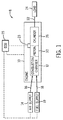
- FIG. 1 illustrates a block diagram of an embodiment of a portion of an engine driven power generation system 8.
- the system 8 includes an engine 10 (e.g., a reciprocating internal combustion engine) having one or more combustion chambers 12 (e.g., 1, 2, 3, 4, 5, 6, 7, 8, 10, 12, 14, 16, 18, 20, or more combustion chambers 12).
- an air supply 14 is configured to provide a pressurized oxidant 16, such as air, oxygen, oxygen-enriched air, oxygen-reduced air, or any combination thereof, to each combustion chamber 12.
- the combustion chamber 12 is also configured to receive a fuel 18 (e.g., a liquid and/or gaseous fuel) from a fuel supply 19, and a fuel-air mixture ignites and combusts within each combustion chamber 12.
- a fuel 18 e.g., a liquid and/or gaseous fuel
- the hot pressurized combustion gases cause a piston 20 adjacent to each combustion chamber 12 to move linearly within a cylinder 26 and convert pressure exerted by the gases into a rotating motion, which causes a shaft 22 to rotate.
- the shaft 22 may be coupled to a load 24, which is powered via rotation of the shaft 22.
- the load 24 may be any suitable device that may generate power via the rotational output of the system 10, such as an electrical generator.
- the fuel 18 may be any suitable gaseous fuel, such as natural gas, associated petroleum gas, propane, biogas, sewage gas, landfill gas, coal mine gas, for example.
- the system 8 disclosed herein may be adapted for use in stationary applications (e.g., in industrial power generating engines) or in mobile applications (e.g., in cars or aircraft).
- the engine 10 may be a two-stroke engine, three-stroke engine, four-stroke engine, five-stroke engine, or six-stroke engine.
- the engine 10 may also include any number of combustion chambers 12, pistons 20, and associated cylinders (e.g., 1-24).
- the system 8 may include a large-scale industrial reciprocating engine having 4, 6, 8, 10, 16, 24 or more pistons 20 reciprocating in cylinders.
- the cylinders and/or the pistons 20 may have a diameter of between approximately 13.5 - 34 centimeters (cm).
- the cylinders and/or the pistons 20 may have a diameter of between approximately 10-40 cm, 15-25 cm, or about 15 cm.
- the system 10 may generate power ranging from 10 kW to 10 MW.
- the engine 10 may operate at less than approximately 1800 revolutions per minute (RPM).
- the engine 10 may operate at less than approximately 2000 RPM, 1900 RPM, 1700 RPM, 1600 RPM, 1500 RPM, 1400 RPM, 1300 RPM, 1200 RPM, 1000 RPM, 900 RPM, or 750 RPM.
- the engine 10 may operate between approximately 750-2000 RPM, 900-1800 RPM, or 1000-1600 RPM.
- the engine 10 may operate at approximately 1800 RPM, 1500 RPM, 1200 RPM, 1000 RPM, or 900 RPM.
- Exemplary engines 10 may include General Electric Company's Jenbacher Engines (e.g., Jenbacher Type 2, Type 3, Type 4, Type 6 or J920 FleXtra) or Waukesha Engines (e.g., Waukesha VGF, VHP, APG, 275GL), for example.
- the driven power generation system 8 may include one or more knock sensors 23 suitable for detecting engine “knock.”
- the knock sensor 23 may be any sensor configured to sense vibrations caused by the engine 10, such as vibration due to detonation, pre-ignition, and or pinging.
- the knock sensor 23 is shown communicatively coupled to a controller, engine control unit (ECU) 25.
- ECU 25 engine control unit
- signals from the knock sensor 23 are communicated to the ECU 25 to determine if knocking conditions (e.g., pinging) exist.
- the ECU 25 may then adjust certain engine 10 parameters to ameliorate or eliminate the knocking conditions.
- the ECU 25 may adjust ignition timing and/or adjust boost pressure to eliminate the knocking.
- the knock sensor 23 may additionally derive that certain vibrations should be further analyzed and categorized to detect, for example, undesired engine conditions.
- FIG. 2 is a side cross-sectional view of an embodiment of a piston assembly 25 having a piston 20 disposed within a cylinder 26 (e.g., an engine cylinder) of the reciprocating engine 10.
- the cylinder 26 has an inner annular wall 28 defining a cylindrical cavity 30 (e.g., bore).
- the piston 20 may be defined by an axial axis or direction 34, a radial axis or direction 36, and a circumferential axis or direction 38.
- the piston 20 includes a top portion 40 (e.g., a top land).
- the top portion 40 generally blocks the fuel 18 and the air 16, or a fuel-air mixture 32, from escaping from the combustion chamber 12 during reciprocating motion of the piston 20.
- the piston 20 is attached to a crankshaft 54 via a connecting rod 56 and a pin 58.
- the crankshaft 54 translates the reciprocating linear motion of the piston 24 into a rotating motion.
- the crankshaft 54 rotates to power the load 24 (shown in FIG. 1 ), as discussed above.
- the combustion chamber 12 is positioned adjacent to the top land 40 of the piston 24.
- a fuel injector 60 provides the fuel 18 to the combustion chamber 12, and an intake valve 62 controls the delivery of air 16 to the combustion chamber 12.
- An exhaust valve 64 controls discharge of exhaust from the engine 10.
- any suitable elements and/or techniques for providing fuel 18 and air 16 to the combustion chamber 12 and/or for discharging exhaust may be utilized, and in some embodiments, no fuel injection is used.
- combustion of the fuel 18 with the air 16 in the combustion chamber 12 cause the piston 20 to move in a reciprocating manner (e.g., back and forth) in the axial direction 34 within the cavity 30 of the cylinder 26.
- crankshaft 54 rotates one half of a revolution.
- engine 10 embodiments may include two-stroke engines, three-stroke engines, four-stroke engines, five-stroke engine, six-stroke engines, or more.
- a sequence including an intake process, a compression process, a power process, and an exhaust process typically occurs.
- the intake process enables a combustible mixture, such as fuel and air, to be pulled into the cylinder 26, thus the intake valve 62 is open and the exhaust valve 64 is closed.
- the compression process compresses the combustible mixture into a smaller space, so both the intake valve 62 and the exhaust valve 64 are closed.
- the power process ignites the compressed fuel-air mixture, which may include a spark ignition through a spark plug system, and/or a compression ignition through compression heat.
- the resulting pressure from combustion then forces the piston 20 to BDC.
- the exhaust process typically returns the piston 20 to TDC while keeping the exhaust valve 64 open. The exhaust process thus expels the spent fuel-air mixture through the exhaust valve 64.
- more than one intake valve 62 and exhaust valve 64 may be used per cylinder 26.
- the depicted engine 10 also includes a crankshaft sensor 66, the knock sensor 23, and the engine control unit (ECU) 25, which includes a processor 72 and memory 74.
- the crankshaft sensor 66 senses the position and/or rotational speed of the crankshaft 54. Accordingly, a crank angle or crank timing information may be derived. That is, when monitoring combustion engines, timing is frequently expressed in terms of crankshaft 54 angle. For example, a full cycle of a four stroke engine 10 may be measured as a 720° cycle.
- the knock sensor 23 may be a Piezo-electric accelerometer, a microelectromechanical system (MEMS) sensor, a Hall effect sensor, a magnetostrictive sensor, and/or any other sensor designed to sense vibration, acceleration, sound, and/or movement.
- sensor 23 may not be a knock sensor in the traditional sense, but any sensor that may sense vibration, pressure, acceleration, deflection, or movement.
- the knock sensor 23 may be capable of detecting signatures even when mounted on the exterior of the cylinder 26. However, the knock sensor 23 may be disposed at various locations in or about the cylinder 26. Additionally, in some embodiments, a single knock sensor 23 may be shared, for example, with one or more adjacent cylinders 26. In other embodiments, each cylinder 26 may include one or more knock sensors 23.
- the crankshaft sensor 66 and the knock sensor 23 are shown in electronic communication with the engine control unit (ECU) 25.
- the ECU 25 includes a processor 72 and a memory 74.
- the memory 74 may store computer instructions that may be executed by the processor 72.
- the ECU 25 monitors and controls and operation of the engine 10, for example, by adjusting combustion timing, valve 62, 64, timing, adjusting the delivery of fuel and oxidant (e.g., air), and so on.
- the techniques described herein may use the ECU 25 to receive data from the crankshaft sensor 66 and the knock sensor 23, and then to creates a "noise" signature by plotting the knock sensor 23 data against the crankshaft 54 position.
- the ECU 25 may then go through the process of analyzing the data to derive normal (e.g.., known and expected noises) and abnormal signatures (e.g., unknown or unexpected noises).
- the ECU 25 may then characterize the abnormal signatures, as described in more detail below.
- the techniques described herein may enable a more optimal and a more efficient operations and maintenance of the engine 10.
- FIGS. 3-6 are illustrative of data that may be undergoing data processing, for example, via a process described in more detail with respect to FIG. 7 and 8 .
- the data for FIGS. 3-6 may include data transmitted via the knock sensor 23 and the crank angle sensor 66.
- FIG. 3 is an embodiment of a raw engine noise plot 75 derived (e.g., by the ECU 25) of noise data measured by the knock sensor 23 in which x-axis 76 is crankshaft 54 position, which is correlative of time.
- the plot 75 is generated when the ECU 25 combines the data received from the knock sensor 23 and the crankshaft sensor 66 during operations of the engine 10.
- an amplitude curve 77 of the knock sensor 23 signal is shown, with an amplitude axis 78. That is, the amplitude curve 77 includes amplitude measurements of vibration data (e.g., noise, sound data) sensed via the knock sensor 23 plotted against crank angle. It should be understood that this is merely a plot of a sample data set, and not intended to limit plots generated by the ECU 25. The curve 77 may then be scaled for further processing, as shown in FIG. 4 .
- vibration data e.g., noise, sound data
- FIG. 4 is an embodiment of a scaled engine noise plot 79, which may be derived by the ECU 25.
- the raw engine noise from amplitude plot 75 shown in FIG. 3 has been scaled to derive a scaled amplitude curve 80.
- a single multiplier has been applied to each data point such that the maximum positive value of the scaled amplitude curve 80 is 1.
- the multiplier applied to each point of curve 80 in order to produce a maximum positive value of 1 may result in negative values that are less than or greater than -1. That is, the maximum negative value may be -0.5, or it may be -1.9, as shown in scaled engine noise plot 79 shown in FIG. 4 .
- FIG. 5 is an embodiment of a scaled engine noise plot 81 with four principle parameters of an attack, decay, sustain, release (ADSR) envelope 82 laid over the top of the plot.
- the ADSR envelope 82 is typically used in music synthesizers in order to mimic the sound of musical instruments.
- the techniques described herein apply the ADSR envelope 82 to knock sensor 23 data to more quickly and efficiently provide for certain noise analysis, as further described below.
- the four principle parameters of the ADSR envelope are attack 83, decay 84, sustain 85, and release 86.
- the attack 80 occurs from the start of the noise to a peak amplitude 87 of the scaled curve 80.
- the decay 84 occurs from in the run down from the peak amplitude to a designated sustain 85 level, which may be some specified percent of the maximum amplitude.
- a designated sustain 85 level which may be some specified percent of the maximum amplitude.
- the order of the four parameters does not have to be attack, decay, sustain, and release.
- the order may be attack, sustain, decay, and release.
- an ASDR, rather than ADSR, envelope would be applied.
- this will be referred to as an "ADSR envelope," but it should be understood that the term applies to a noise regardless of the order of the parameters.
- the sustain 85 level is the main level during the noise's duration. In some embodiments, the sustain 85 level may occur at 55% of the maximum amplitude.
- the sustain 85 level may be 35%, 40%, 45%, 50%, 60%, or 65% of the maximum amplitude.
- a user, or the ECU 25, may check whether the sustain level is as desired by determining whether the sustain 85 level is held for at least 15% of the duration of the signature. If the sustain 85 lasts more than 15% of the duration of the signature, the sustain 85 level is set as desired. The release 86 occurs during the run down from the sustain 85 level back to zero.
- FIG. 6 shows the same scaled engine noise plot 79 shown in FIGS. 4 and 5 with certain tones overlaid.
- the ECU 25 may extract three to five of the strongest frequencies in the noise and convert them into musical tones. For example, a lookup table mapping frequency ranges to musical tones may be used. Additionally or alternatively, equations may be used based on the observation that pitch is typically perceived as the logarithm of frequency for equal temperament systems of tuning, or equations for other musical temperament systems. In other embodiments, more or less frequencies may be extracted.
- the three prominent (e.g., extracted) tones are C#5, E4, and B3. It should be understood, however, and these three tones are merely examples of possible tones and not intended to limit what tones may be present in a recorded noise.
- FIG. 7 is a flow chart showing an embodiment of a process 88 for characterizing a noise, such as noise sensed via the knock sensor 23.
- the process 88 may be implemented as computer instructions or executable code stored in the memory 74 and executable by the processor 72 of the ECU 25.
- a sample of data is taken using the knock sensor 23 and the crankshaft sensor 66.
- the sensors 66, 23 collect data and then transmit the data to the ECU 25.
- the ECU 25 logs the crankshaft 54 angles at the start of data collection and at the end of data collection, as well as the time and/or crankshaft angle at the maximum (e.g., amplitude 87) and minimum amplitudes.
- the ECU 25 pre-conditions the knock sensor 23 data.
- This block 92 includes plotting the raw knock sensor 23 data against crankshaft 54 position. A sample raw engine noise plot was shown in FIG. 3 as the amplitude plot 75.
- This block 92 includes scaling the raw engine noise data.
- the ECU 25 determines a multiplier that would result in a maximum amplitude of positive 1. It should be noted that the maximum negative value has no effect on multiplier selection.
- the ECU 25 then multiplies each data point (e.g., data point in amplitude curve 77) by the multiplier, to derive the scaled amplitude curve 80, as shown in FIG. 4 .
- the scaled engine noise plot 79 in FIG. 4 showing the scaled amplitude curve 80 is merely an example and not intended to limit the scope of this disclosure to plots that look the same or similar to scaled engine noise plot 79.
- the ECU 25 applies the ASDR envelope 82 to the engine noise signal.
- the processing in this block was discussed in describing FIG. 5 .
- the ASDR envelope 82 is used to divide a noise data set into four different parameters or phases (attack 83, decay 84, sustain 85, release 86).
- attack 83, decay 84, sustain 85, release 86 the order of the four parameters does not have to be attack, decay, sustain, and release.
- the order may be attack, sustain, decay, and release.
- this will be referred to as an "ADSR envelope," but it should be understood that the term applies to a noise regardless of the order of the parameters.
- the ASDR envelope 82 is used the process of reproducing a musical sound like that of a trumpet.
- the ASDR envelope may be used to categorize and characterize noises so they can be cataloged and sorted, either for later analysis, real-time analysis, or some other purpose.
- the four principle parameters of the ADSR envelope 82 are attack 83, decay 84, sustain 85, and release 86.
- the attack 83 occurs from the start of the noise to the peak amplitude 87.
- the decay 84 occurs from in the run down from the peak amplitude 87 to a designated sustain 85 level, which is some specified percent of the maximum amplitude.
- the sustain 85 level is the main level during the noise's duration. In some embodiments, the sustain 85 level may occur at 55% of the maximum amplitude.
- the sustain 85 level may be 35%, 40%, 45%, 50%, 60%, or 65% of the maximum amplitude.
- a user, or the ECU 25, may check whether the sustain level is as desired by determining whether the sustain 85 level is held for at least 15% of the duration of the signature. If the sustain 85 lasts more than 15% of the duration of the signature, the sustain 85 level is set as desired. The release 86 occurs during the run down from the sustain 85 level back to zero.
- the ECU 25 measures the time from zero to maximum amplitude 87 (the maximum amplitude should have a value of 1). The ECU 25 then measures the run down time from the maximum amplitude 87 to the designated sustain level 85. The ECU 25 then measures the level and time that the noise sustains. Finally, the ECU 25 measures the time it takes for the noise to run down from the sustain level 85 to zero. The ECU 25 then logs the ADSR vectors or segments defining the ADSR envelope 82.
- the ECU 25 derives tonal information (e.g., musical tones) from the data. This block was discussed in the description of FIG. 6 . During this block, the ECU 25 extracts tonal information from the data, identifying the three to five strongest tones in the data.
- FIG. 6 shows three tones derived from the signal, C#5, E4, and B3. The ECU 25 may derive five or more tones from the data. Though FIG. 6 shows tones C#5, E4, and B3, it should be understood that these tones are examples and the ECU 25 may derive any tones from the data.
- the ECU 25 then logs the derived tonal information, which may include the frequency of the fundamental derived tones (i.e., the lowest frequency tones), the order of the fundamental derived tones, the frequency of the harmonic derived tones (i.e., tones with a frequency that is an integer multiple of the fundamental frequency), the order of the harmonic derived tones, and any other relevant tonal information.
- the fundamental derived tones i.e., the lowest frequency tones
- the order of the fundamental derived tones i.e., the order of the fundamental derived tones
- the frequency of the harmonic derived tones i.e., tones with a frequency that is an integer multiple of the fundamental frequency
- the order of the harmonic derived tones i.e., tones with a frequency that is an integer multiple of the fundamental frequency
- the ECU creates a fingerprint 100 based upon the ASDR envelope 82 and the tonal information derived in blocks 94 and 96.
- the fingerprint 100 includes a characterization of the abnormal or unidentifiable noise, breaking the noise up into its component parts (e.g., ADSR envelope 82 components 83, 84, 85, 86) and quantifying those parts so the noise can be cataloged, categorized, and sorted.
- fingerprint 100 is based mostly upon the ADSR envelope in block 94 and the tonal information derived in block 96.
- the fingerprint 100 is identified and checked. Using a number of techniques, which will be described later, the fingerprint 100 may be modified or added to and then checked again.
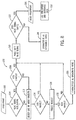
- FIG. 8 is a flow chart showing further details of an embodiment of process 102, which identifies the fingerprint 100 depicted in FIG. 7 .
- the process 102 may the implemented as computer instructions or executable code stored in the memory 74 and executable by the processor 72 of the ECU 25.
- decision 104 the ECU 25 determines whether or not the noise signal is modulating (i.e., changing from one tone to another). If the signal is not modulating (decision 104), then the ECU 25 moves on to block 112 and attempts to find a matching wavelet.
- a wavelet effectively a piece or component of a wave, is a wave-like oscillation with an amplitude that begins at zero, increases, decreases, or both, and then returns to zero.
- Wavelets can be modified by adjusting the frequency, amplitude, and duration, which makes them very useful in signal processing. For example, in continuous wavelet transforms a given signal may be reconstructed by integrating over the various modified frequency components. Commonly used "mother" wavelets include Meyer, Morlet, and Mexican hat wavelets. However, new wavelets may also be created if the mother wavelets do not fit.
- a chirp is a signal in which the frequency increases or decreases with time.
- a wavelet is a piece of a wave
- a chirplet is a piece of a chirp.
- the characteristics of a chirplet can be modified, and then multiple chirplets combined (i.e., a chirplet transform), in order to approximate a signal.
- a chirplet may modulate (i.e., change frequency) upward or downward.
- the ECU 25 may adjust the modulation of chirplets in order to fit the chirplets to the noise signal.
- the ECU 25 logs whether there was a chirplet that fit the signal, and if so, the first frequency of the chirplet, the second frequency of the chirplet, and the rate of chirplet modulation in frequency/(crank angle) or frequency per second.
- the ECU 25 then moves to block 110, in which the ECU 25 phase shifts the noise signal in order to check the fingerprint 100.
- the ECU 25 creates a generated noise signal based upon the ASDR envelope 82 vectors or other components, extracted tonal information, and chirplet or wavelet fits.
- the ECU 25 then shifts (block 110) the generated signal 180 degrees out of phase. If the characterization of the noise signal is correct, the phase-shifted generated noise signal should cancel out the noise signal.
- the ECU 25 moves on to block 112 and attempts to fit a wavelet to the noise signal.
- the ECU 25 selects one or more wavelets that may fit the noise signal.
- the selected wavelet or wavelets may be a Meyer wavelet, a Morlet wavelet, a Mexican hat wavelet, or some other known wavelet.
- decision 114 the ECU 25 determines whether or not the selected wavelet or wavelets fits the noise signal. If the selected wavelet fits (decision 114), the ECU 25 logs that there was a wavelet fit, the mother wavelet type, the first scale range of the wavelet, and the second scale range of the wavelet.
- the ECU 25 moves on to block 110, in which the ECU 25 phase shifts the noise signal in order to check the fingerprint 100. If one of the selected wavelets does not fit the noise signal (decision 114), the ECU 25 may move on to block 116 and create a wavelet. In decision 118, the ECU 25 determines if the newly created wavelet fits the noise signal. If the created wavelet fits (decision 118), the ECU 25 logs that there was a wavelet fit, the first scale range of the wavelet, and the second scale range of the wavelet. If the created wavelet fits the noise signal (decision 118), the ECU 25 moves on to block 110, in which the ECU phase shifts the noise signal in order to check the fingerprint 100. If the new wavelet does not fit (decision 118), the ECU 25 moves on to block 120 in which it characterizes the noise signal as broadband noise.
- the ECU 25 will check the fit by attempting noise cancellation. Accordingly, in block 110, the ECU 25 creates a generated noise signal based upon the ASDR envelope 82 vectors or other components, extracted tonal information, and chirplet or wavelet fits. The ECU 25 then shifts (block 110) the generated signal by 180 degrees. The ECU 25 then determines (decision 122) whether the shifted signal cancels out the original noise signal within a desired residual tolerance.
- the ECU 25 determines that the fingerprint 100 is a "good" fingerprint 126 and moves on to block 128, in which the ECU 25 logs the coefficients and associated data, which may include the root mean squared (RMS) value of the signal, or the RMS error.
- RMS root mean squared
- the ECU 25 may log other data as well, including, but not limited to crankshaft angles at the beginning or end of the signal, ASDR envelope 82 vectors or other ADSR components, fundamental spectral tones, harmonic spectral tones, order of spectral tones, order of harmonic tones, whether a chirplet fit, the first chirplet frequency, the second chirplet frequency, the rate of chirplet modulation, whether a wavelet fit, the mother wavelet type, the first scale range of the wavelet, the second scale range of the wavelet, the maximum amplitude value and time, the minimum amplitude value and time, the RMS value of the signal, the RMS error of the signal against the generated signal, and whether or not the noise is classified as broadband noise.
- This logged data, and other data logged allows the ECU 25 to characterize and categorize most unknown noises so these noises can be stored on the memory component 74 of the ECU 25, perhaps transferred to some other memory device, and then logged and sorted in a database for future analysis. If, on the other hand, the ECU 25 determines (decision 122) that the shifted signal did not cancel out the original noise signal within a residual tolerance, the ECU 25 moves on to block 124 in which the noise signal is characterized as broadband noise.
- Technical effects of the invention include characterizing a noise signal and deriving a signature from the noise signal, which may additionally include preconditioning the noise signal, applying an ASDR envelope to the noise signal, extracting tonal information (e.g., musical tones) from the noise signal and fitting the noise signal to a chirplet and/or a wavelet.
- preconditioning the noise signal applying an ASDR envelope to the noise signal
- extracting tonal information e.g., musical tones
Abstract
Description
- The subject matter disclosed herein relates to knock sensors, and more specifically, to knock sensors suitable for characterizing certain noise.
- Combustion engines typically combust a carbonaceous fuel, such as natural gas, gasoline, diesel, and the like, and use the corresponding expansion of high temperature and pressure gases to apply a force to certain components of the engine, e.g., piston disposed in a cylinder, to move the components over a distance. Each cylinder may include one or more valves that open and close correlative with combustion of the carbonaceous fuel. For example, an intake valve may direct an oxidizer such as air into the cylinder, which is then mixed with fuel and combusted. Combustion fluids, e.g., hot gases, may then be directed to exit the cylinder via an exhaust valve. Accordingly, the carbonaceous fuel is transformed into mechanical motion, useful in driving a load. For example, the load may be a generator that produces electric power.
- Knock sensors can be used to monitor multi-cylinder combustion engines. A knock sensor can be mounted to the exterior of an engine cylinder and used to determine whether or not the engine is running as desired. Sometimes a knock sensor detects a noise that may not be identifiable at the time. It would be desirable to have a way to characterize the noise.
- Certain embodiments commensurate in scope with the originally claimed invention are summarized below. These embodiments are not intended to limit the scope of the claimed invention, but rather these embodiments are intended only to provide a brief summary of possible forms of the invention. Indeed, the invention may encompass a variety of forms that may be similar to or different from the embodiments set forth below.
- In a first embodiment, a method of characterizing a noise signal includes receiving a noise signal sensed by a knock sensor coupled to a reciprocating device, preconditioning the noise signal to derive a preconditioned noise signal, applying an ADSR envelope to the preconditioned noise signal, extracting tonal information from the preconditioned noise signal, and creating a fingerprint of the noise signal based on the ADSR envelope, the tonal information, or a combination thereof
- In a second embodiment, a system includes a controller configured to control a reciprocating device. The controller has a processor configured to receive a noise signal sensed by a knock sensor coupled to a reciprocating device, precondition the noise signal to derive a preconditioned noise signal, apply an ADSR envelope to the preconditioned noise signal, extract tonal information from the preconditioned noise signal, and create a fingerprint of the noise signal based on the ADSR envelope, the tonal information, or a combination thereof.
- In a third embodiment, a non-transitory computer readable medium includes executable instructions that when executed cause a processor to receive, from a knock sensor coupled to a reciprocating device, noise data, derive, from the noise data, a noise signature, scale the noise signature such that the noise signature has a maximum amplitude of 1, apply an ASDR envelope to the noise signature, extract tonal information from the noise signature, fit the noise signature to a chirplet or a wavelet; and check a characterization of the noise signature using noise cancellation.
- These and other features, aspects, and advantages of the present invention will become better understood when the following detailed description is read with reference to the accompanying drawings in which like characters represent like parts throughout the drawings, wherein:
-
FIG. 1 is a block diagram of an embodiment of a portion of an engine driven power generation system in accordance with aspects of the present disclosure; -
FIG. 2 is a side cross-sectional view of an embodiment of a piston assembly within a cylinder of the reciprocating engine shown inFIG. 1 in accordance with aspects of the present disclosure; -
FIG. 3 is an embodiment of an engine noise plot of data measured by the knock sensor shown inFIG. 2 in accordance with aspects of the present disclosure; -
FIG. 4 is an embodiment of a scaled version of the sample engine noise plot shown inFIG. 3 in accordance with aspects of the present disclosure; -
FIG. 5 is an embodiment of a sample scaled engine noise plot shown inFIG. 4 with four principle parameters of an attack, decay, sustain, release (ADSR) envelope overlaid in accordance with aspects of the present disclosure; -
FIG. 6 is an embodiment of a scaled engine noise plot and ASDR envelope shown inFIG. 5 with the extracted tones overlaid in accordance with aspects of the present disclosure; -
FIG. 7 is a flow chart showing an embodiment of a process for characterizing a noise in accordance with aspects of the present disclosure; -
FIG. 8 is a flow chart showing an embodiment of a process for identifying a fingerprint shown inFIG. 7 in accordance with aspects of the present disclosure. - One or more specific embodiments of the present invention will be described below. In an effort to provide a concise description of these embodiments, all features of an actual implementation may not be described in the specification. It should be appreciated that in the development of any such actual implementation, as in any engineering or design project, numerous implementation-specific decisions must be made to achieve the developers' specific goals, such as compliance with system-related and business-related constraints, which may vary from one implementation to another. Moreover, it should be appreciated that such a development effort might be complex and time consuming, but would nevertheless be a routine undertaking of design, fabrication, and manufacture for those of ordinary skill having the benefit of this disclosure.
- When introducing elements of various embodiments of the present invention, the articles "a," "an," "the," and "said" are intended to mean that there are one or more of the elements. The terms "comprising," "including," and "having" are intended to be inclusive and mean that there may be additional elements other than the listed elements.
- When using a knock sensor to monitor a reciprocating device (e.g., a combustion engine), occasionally the knock sensor system records a noise, such as an abnormal or undesired noise that may not be identified at that time. Rather than ignore and discard the unidentifiable noises, it may be advantageous to save recordings of unidentifiable noises for analysis at a later date. However, having a log of uncharacterized unidentifiable noises that cannot be sorted greatly reduces the utility of the data set. As such, it would be beneficial to characterize and/or categorize the collected unidentifiable noises so they can be more easily analyzed, thus making future (or current) analysis of the noises easier.
- Advantageously, the techniques described herein may create a sound "fingerprint" of certain engine sounds or noise. As described in further detail below, systems and method are provided for identifying and classifying noise via an Attack-Decay-Sustain-Release (ASDR) envelope and/or joint time-frequency techniques. The joint time-frequency techniques may include cepstrum techniques, quefrency techniques, chirplet techniques, and/or wavelet techniques to develop an acoustic model or fingerprint of the unknown noise, as described in more detail below.
- Turning to the drawings,
FIG. 1 illustrates a block diagram of an embodiment of a portion of an engine drivenpower generation system 8. As described in detail below, thesystem 8 includes an engine 10 (e.g., a reciprocating internal combustion engine) having one or more combustion chambers 12 (e.g., 1, 2, 3, 4, 5, 6, 7, 8, 10, 12, 14, 16, 18, 20, or more combustion chambers 12). ThoughFIG. 1 shows acombustion engine 10, it should be understood that any reciprocating device may be used. Anair supply 14 is configured to provide a pressurizedoxidant 16, such as air, oxygen, oxygen-enriched air, oxygen-reduced air, or any combination thereof, to eachcombustion chamber 12. Thecombustion chamber 12 is also configured to receive a fuel 18 (e.g., a liquid and/or gaseous fuel) from afuel supply 19, and a fuel-air mixture ignites and combusts within eachcombustion chamber 12. The hot pressurized combustion gases cause apiston 20 adjacent to eachcombustion chamber 12 to move linearly within acylinder 26 and convert pressure exerted by the gases into a rotating motion, which causes ashaft 22 to rotate. Further, theshaft 22 may be coupled to aload 24, which is powered via rotation of theshaft 22. For example, theload 24 may be any suitable device that may generate power via the rotational output of thesystem 10, such as an electrical generator. Additionally, although the following discussion refers to air as theoxidant 16, any suitable oxidant may be used with the disclosed embodiments. Similarly, thefuel 18 may be any suitable gaseous fuel, such as natural gas, associated petroleum gas, propane, biogas, sewage gas, landfill gas, coal mine gas, for example. - The
system 8 disclosed herein may be adapted for use in stationary applications (e.g., in industrial power generating engines) or in mobile applications (e.g., in cars or aircraft). Theengine 10 may be a two-stroke engine, three-stroke engine, four-stroke engine, five-stroke engine, or six-stroke engine. Theengine 10 may also include any number ofcombustion chambers 12,pistons 20, and associated cylinders (e.g., 1-24). For example, in certain embodiments, thesystem 8 may include a large-scale industrial reciprocating engine having 4, 6, 8, 10, 16, 24 ormore pistons 20 reciprocating in cylinders. In some such cases, the cylinders and/or thepistons 20 may have a diameter of between approximately 13.5 - 34 centimeters (cm). In some embodiments, the cylinders and/or thepistons 20 may have a diameter of between approximately 10-40 cm, 15-25 cm, or about 15 cm. Thesystem 10 may generate power ranging from 10 kW to 10 MW. In some embodiments, theengine 10 may operate at less than approximately 1800 revolutions per minute (RPM). In some embodiments, theengine 10 may operate at less than approximately 2000 RPM, 1900 RPM, 1700 RPM, 1600 RPM, 1500 RPM, 1400 RPM, 1300 RPM, 1200 RPM, 1000 RPM, 900 RPM, or 750 RPM. In some embodiments, theengine 10 may operate between approximately 750-2000 RPM, 900-1800 RPM, or 1000-1600 RPM. In some embodiments, theengine 10 may operate at approximately 1800 RPM, 1500 RPM, 1200 RPM, 1000 RPM, or 900 RPM.Exemplary engines 10 may include General Electric Company's Jenbacher Engines (e.g.,Jenbacher Type 2, Type 3, Type 4, Type 6 or J920 FleXtra) or Waukesha Engines (e.g., Waukesha VGF, VHP, APG, 275GL), for example. - The driven
power generation system 8 may include one ormore knock sensors 23 suitable for detecting engine "knock." Theknock sensor 23 may be any sensor configured to sense vibrations caused by theengine 10, such as vibration due to detonation, pre-ignition, and or pinging. Theknock sensor 23 is shown communicatively coupled to a controller, engine control unit (ECU) 25. During operations, signals from theknock sensor 23 are communicated to theECU 25 to determine if knocking conditions (e.g., pinging) exist. TheECU 25 may then adjustcertain engine 10 parameters to ameliorate or eliminate the knocking conditions. For example, theECU 25 may adjust ignition timing and/or adjust boost pressure to eliminate the knocking. As further described herein, theknock sensor 23 may additionally derive that certain vibrations should be further analyzed and categorized to detect, for example, undesired engine conditions. -
FIG. 2 is a side cross-sectional view of an embodiment of apiston assembly 25 having apiston 20 disposed within a cylinder 26 (e.g., an engine cylinder) of thereciprocating engine 10. Thecylinder 26 has an innerannular wall 28 defining a cylindrical cavity 30 (e.g., bore). Thepiston 20 may be defined by an axial axis ordirection 34, a radial axis ordirection 36, and a circumferential axis ordirection 38. Thepiston 20 includes a top portion 40 (e.g., a top land). Thetop portion 40 generally blocks thefuel 18 and theair 16, or a fuel-air mixture 32, from escaping from thecombustion chamber 12 during reciprocating motion of thepiston 20. - As shown, the
piston 20 is attached to acrankshaft 54 via a connectingrod 56 and apin 58. Thecrankshaft 54 translates the reciprocating linear motion of thepiston 24 into a rotating motion. As thepiston 20 moves, thecrankshaft 54 rotates to power the load 24 (shown inFIG. 1 ), as discussed above. As shown, thecombustion chamber 12 is positioned adjacent to thetop land 40 of thepiston 24. Afuel injector 60 provides thefuel 18 to thecombustion chamber 12, and anintake valve 62 controls the delivery ofair 16 to thecombustion chamber 12. Anexhaust valve 64 controls discharge of exhaust from theengine 10. However, it should be understood that any suitable elements and/or techniques for providingfuel 18 andair 16 to thecombustion chamber 12 and/or for discharging exhaust may be utilized, and in some embodiments, no fuel injection is used. In operation, combustion of thefuel 18 with theair 16 in thecombustion chamber 12 cause thepiston 20 to move in a reciprocating manner (e.g., back and forth) in theaxial direction 34 within thecavity 30 of thecylinder 26. - During operations, when the
piston 20 is at the highest point in thecylinder 26 it is in a position called top dead center (TDC). When thepiston 20 is at its lowest point in thecylinder 26, it is in a position called bottom dead center (BDC). As thepiston 20 moves from top to bottom or from bottom to top, thecrankshaft 54 rotates one half of a revolution. Each movement of thepiston 20 from top to bottom or from bottom to top is called a stroke, andengine 10 embodiments may include two-stroke engines, three-stroke engines, four-stroke engines, five-stroke engine, six-stroke engines, or more. - During
engine 10 operations, a sequence including an intake process, a compression process, a power process, and an exhaust process typically occurs. The intake process enables a combustible mixture, such as fuel and air, to be pulled into thecylinder 26, thus theintake valve 62 is open and theexhaust valve 64 is closed. The compression process compresses the combustible mixture into a smaller space, so both theintake valve 62 and theexhaust valve 64 are closed. The power process ignites the compressed fuel-air mixture, which may include a spark ignition through a spark plug system, and/or a compression ignition through compression heat. The resulting pressure from combustion then forces thepiston 20 to BDC. The exhaust process typically returns thepiston 20 to TDC while keeping theexhaust valve 64 open. The exhaust process thus expels the spent fuel-air mixture through theexhaust valve 64. It is to be noted that more than oneintake valve 62 andexhaust valve 64 may be used percylinder 26. - The depicted
engine 10 also includes acrankshaft sensor 66, theknock sensor 23, and the engine control unit (ECU) 25, which includes aprocessor 72 andmemory 74. Thecrankshaft sensor 66 senses the position and/or rotational speed of thecrankshaft 54. Accordingly, a crank angle or crank timing information may be derived. That is, when monitoring combustion engines, timing is frequently expressed in terms ofcrankshaft 54 angle. For example, a full cycle of a fourstroke engine 10 may be measured as a 720° cycle. Theknock sensor 23 may be a Piezo-electric accelerometer, a microelectromechanical system (MEMS) sensor, a Hall effect sensor, a magnetostrictive sensor, and/or any other sensor designed to sense vibration, acceleration, sound, and/or movement. In other embodiments,sensor 23 may not be a knock sensor in the traditional sense, but any sensor that may sense vibration, pressure, acceleration, deflection, or movement. - Because of the percussive nature of the
engine 10, theknock sensor 23 may be capable of detecting signatures even when mounted on the exterior of thecylinder 26. However, theknock sensor 23 may be disposed at various locations in or about thecylinder 26. Additionally, in some embodiments, asingle knock sensor 23 may be shared, for example, with one or moreadjacent cylinders 26. In other embodiments, eachcylinder 26 may include one ormore knock sensors 23. Thecrankshaft sensor 66 and theknock sensor 23 are shown in electronic communication with the engine control unit (ECU) 25. TheECU 25 includes aprocessor 72 and amemory 74. Thememory 74 may store computer instructions that may be executed by theprocessor 72. TheECU 25 monitors and controls and operation of theengine 10, for example, by adjusting combustion timing,valve - Advantageously, the techniques described herein may use the
ECU 25 to receive data from thecrankshaft sensor 66 and theknock sensor 23, and then to creates a "noise" signature by plotting theknock sensor 23 data against thecrankshaft 54 position. TheECU 25 may then go through the process of analyzing the data to derive normal (e.g.., known and expected noises) and abnormal signatures (e.g., unknown or unexpected noises). TheECU 25 may then characterize the abnormal signatures, as described in more detail below. By providing for signature analysis, the techniques described herein may enable a more optimal and a more efficient operations and maintenance of theengine 10. -
FIGS. 3-6 are illustrative of data that may be undergoing data processing, for example, via a process described in more detail with respect toFIG. 7 and8 . The data forFIGS. 3-6 may include data transmitted via theknock sensor 23 and thecrank angle sensor 66. For example,FIG. 3 is an embodiment of a rawengine noise plot 75 derived (e.g., by the ECU 25) of noise data measured by theknock sensor 23 in which x-axis 76 is crankshaft 54 position, which is correlative of time. Theplot 75 is generated when theECU 25 combines the data received from theknock sensor 23 and thecrankshaft sensor 66 during operations of theengine 10. In the depicted embodiment, anamplitude curve 77 of theknock sensor 23 signal is shown, with anamplitude axis 78. That is, theamplitude curve 77 includes amplitude measurements of vibration data (e.g., noise, sound data) sensed via theknock sensor 23 plotted against crank angle. It should be understood that this is merely a plot of a sample data set, and not intended to limit plots generated by theECU 25. Thecurve 77 may then be scaled for further processing, as shown inFIG. 4 . -
FIG. 4 is an embodiment of a scaledengine noise plot 79, which may be derived by theECU 25. In the scaledplot 79, the raw engine noise fromamplitude plot 75 shown inFIG. 3 has been scaled to derive a scaledamplitude curve 80. In this case, a single multiplier has been applied to each data point such that the maximum positive value of the scaledamplitude curve 80 is 1. Note that the multiplier applied to each point ofcurve 80 in order to produce a maximum positive value of 1 may result in negative values that are less than or greater than -1. That is, the maximum negative value may be -0.5, or it may be -1.9, as shown in scaledengine noise plot 79 shown inFIG. 4 . -
FIG. 5 is an embodiment of a scaledengine noise plot 81 with four principle parameters of an attack, decay, sustain, release (ADSR)envelope 82 laid over the top of the plot. TheADSR envelope 82 is typically used in music synthesizers in order to mimic the sound of musical instruments. Advantageously, the techniques described herein apply theADSR envelope 82 to knocksensor 23 data to more quickly and efficiently provide for certain noise analysis, as further described below. The four principle parameters of the ADSR envelope areattack 83,decay 84, sustain 85, andrelease 86. Theattack 80 occurs from the start of the noise to apeak amplitude 87 of the scaledcurve 80. Thedecay 84 occurs from in the run down from the peak amplitude to a designated sustain 85 level, which may be some specified percent of the maximum amplitude. It should be understood that the order of the four parameters does not have to be attack, decay, sustain, and release. For example, for some noises, the order may be attack, sustain, decay, and release. In such cases, an ASDR, rather than ADSR, envelope would be applied. For the sake of simplicity, this will be referred to as an "ADSR envelope," but it should be understood that the term applies to a noise regardless of the order of the parameters. The sustain 85 level is the main level during the noise's duration. In some embodiments, the sustain 85 level may occur at 55% of the maximum amplitude. In other embodiments, the sustain 85 level may be 35%, 40%, 45%, 50%, 60%, or 65% of the maximum amplitude. A user, or theECU 25, may check whether the sustain level is as desired by determining whether the sustain 85 level is held for at least 15% of the duration of the signature. If the sustain 85 lasts more than 15% of the duration of the signature, the sustain 85 level is set as desired. Therelease 86 occurs during the run down from the sustain 85 level back to zero. -
FIG. 6 shows the same scaledengine noise plot 79 shown inFIGS. 4 and5 with certain tones overlaid. After applying theADSR envelope 82, theECU 25 may extract three to five of the strongest frequencies in the noise and convert them into musical tones. For example, a lookup table mapping frequency ranges to musical tones may be used. Additionally or alternatively, equations may be used based on the observation that pitch is typically perceived as the logarithm of frequency for equal temperament systems of tuning, or equations for other musical temperament systems. In other embodiments, more or less frequencies may be extracted. In theplot 81 shown inFIG. 6 the three prominent (e.g., extracted) tones areC# 5, E4, and B3. It should be understood, however, and these three tones are merely examples of possible tones and not intended to limit what tones may be present in a recorded noise. -
FIG. 7 is a flow chart showing an embodiment of aprocess 88 for characterizing a noise, such as noise sensed via theknock sensor 23. By characterizing an abnormal or unidentifiable noise, the noise can be logged and sorted for analysis, including future analysis and/or real-time analysis. Theprocess 88 may be implemented as computer instructions or executable code stored in thememory 74 and executable by theprocessor 72 of theECU 25. Inblock 90, a sample of data is taken using theknock sensor 23 and thecrankshaft sensor 66. For example, thesensors ECU 25. TheECU 25 then logs thecrankshaft 54 angles at the start of data collection and at the end of data collection, as well as the time and/or crankshaft angle at the maximum (e.g., amplitude 87) and minimum amplitudes. - In
block 92, theECU 25 pre-conditions theknock sensor 23 data. Thisblock 92 includes plotting theraw knock sensor 23 data againstcrankshaft 54 position. A sample raw engine noise plot was shown inFIG. 3 as theamplitude plot 75. Thisblock 92 includes scaling the raw engine noise data. To scale the data, theECU 25 determines a multiplier that would result in a maximum amplitude of positive 1. It should be noted that the maximum negative value has no effect on multiplier selection. TheECU 25 then multiplies each data point (e.g., data point in amplitude curve 77) by the multiplier, to derive the scaledamplitude curve 80, as shown inFIG. 4 . It should be understood that the scaledengine noise plot 79 inFIG. 4 showing the scaledamplitude curve 80 is merely an example and not intended to limit the scope of this disclosure to plots that look the same or similar to scaledengine noise plot 79. - In
block 94, theECU 25 applies theASDR envelope 82 to the engine noise signal. The processing in this block was discussed in describingFIG. 5 . TheASDR envelope 82 is used to divide a noise data set into four different parameters or phases (attack 83,decay 84, sustain 85, release 86). As previously discussed, it should be understood that the order of the four parameters does not have to be attack, decay, sustain, and release. For example, for some noises, the order may be attack, sustain, decay, and release. For the sake of simplicity, this will be referred to as an "ADSR envelope," but it should be understood that the term applies to a noise regardless of the order of the parameters. Traditionally, theASDR envelope 82 is used the process of reproducing a musical sound like that of a trumpet. However, in the techniques described herein, the ASDR envelope may be used to categorize and characterize noises so they can be cataloged and sorted, either for later analysis, real-time analysis, or some other purpose. The four principle parameters of theADSR envelope 82 areattack 83,decay 84, sustain 85, andrelease 86. Theattack 83 occurs from the start of the noise to thepeak amplitude 87. Thedecay 84 occurs from in the run down from thepeak amplitude 87 to a designated sustain 85 level, which is some specified percent of the maximum amplitude. The sustain 85 level is the main level during the noise's duration. In some embodiments, the sustain 85 level may occur at 55% of the maximum amplitude. In other embodiments, the sustain 85 level may be 35%, 40%, 45%, 50%, 60%, or 65% of the maximum amplitude. A user, or theECU 25, may check whether the sustain level is as desired by determining whether the sustain 85 level is held for at least 15% of the duration of the signature. If the sustain 85 lasts more than 15% of the duration of the signature, the sustain 85 level is set as desired. Therelease 86 occurs during the run down from the sustain 85 level back to zero. Inblock 94 theECU 25 measures the time from zero to maximum amplitude 87 (the maximum amplitude should have a value of 1). TheECU 25 then measures the run down time from themaximum amplitude 87 to the designated sustainlevel 85. TheECU 25 then measures the level and time that the noise sustains. Finally, theECU 25 measures the time it takes for the noise to run down from the sustainlevel 85 to zero. TheECU 25 then logs the ADSR vectors or segments defining theADSR envelope 82. - In
block 96, theECU 25 derives tonal information (e.g., musical tones) from the data. This block was discussed in the description ofFIG. 6 . During this block, theECU 25 extracts tonal information from the data, identifying the three to five strongest tones in the data.FIG. 6 shows three tones derived from the signal,C# 5, E4, and B3. TheECU 25 may derive five or more tones from the data. ThoughFIG. 6 showstones C# 5, E4, and B3, it should be understood that these tones are examples and theECU 25 may derive any tones from the data. TheECU 25 then logs the derived tonal information, which may include the frequency of the fundamental derived tones (i.e., the lowest frequency tones), the order of the fundamental derived tones, the frequency of the harmonic derived tones (i.e., tones with a frequency that is an integer multiple of the fundamental frequency), the order of the harmonic derived tones, and any other relevant tonal information. - In
block 98 the ECU creates afingerprint 100 based upon theASDR envelope 82 and the tonal information derived inblocks fingerprint 100 includes a characterization of the abnormal or unidentifiable noise, breaking the noise up into its component parts (e.g.,ADSR envelope 82components fingerprint 100 is based mostly upon the ADSR envelope inblock 94 and the tonal information derived inblock 96. - In
block 102, thefingerprint 100 is identified and checked. Using a number of techniques, which will be described later, thefingerprint 100 may be modified or added to and then checked again. -
FIG. 8 is a flow chart showing further details of an embodiment ofprocess 102, which identifies thefingerprint 100 depicted inFIG. 7 . Theprocess 102 may the implemented as computer instructions or executable code stored in thememory 74 and executable by theprocessor 72 of theECU 25. Indecision 104, theECU 25 determines whether or not the noise signal is modulating (i.e., changing from one tone to another). If the signal is not modulating (decision 104), then theECU 25 moves on to block 112 and attempts to find a matching wavelet. A wavelet, effectively a piece or component of a wave, is a wave-like oscillation with an amplitude that begins at zero, increases, decreases, or both, and then returns to zero. Wavelets can be modified by adjusting the frequency, amplitude, and duration, which makes them very useful in signal processing. For example, in continuous wavelet transforms a given signal may be reconstructed by integrating over the various modified frequency components. Commonly used "mother" wavelets include Meyer, Morlet, and Mexican hat wavelets. However, new wavelets may also be created if the mother wavelets do not fit. - If the sound is modulating (decision 104), the
ECU 25 moves on todecision 108 and determines whether or not the noise signal fits a chirplet. A chirp is a signal in which the frequency increases or decreases with time. Just as a wavelet is a piece of a wave, a chirplet is a piece of a chirp. Much like wavelets, the characteristics of a chirplet can be modified, and then multiple chirplets combined (i.e., a chirplet transform), in order to approximate a signal. A chirplet may modulate (i.e., change frequency) upward or downward. Indecision 108, theECU 25 may adjust the modulation of chirplets in order to fit the chirplets to the noise signal. If theECU 25, after adjusting the modulation of chirplets, can adjust chriplets to fit the noise signal, then theECU 25 logs whether there was a chirplet that fit the signal, and if so, the first frequency of the chirplet, the second frequency of the chirplet, and the rate of chirplet modulation in frequency/(crank angle) or frequency per second. TheECU 25 then moves to block 110, in which theECU 25 phase shifts the noise signal in order to check thefingerprint 100. Inblock 110, theECU 25 creates a generated noise signal based upon theASDR envelope 82 vectors or other components, extracted tonal information, and chirplet or wavelet fits. TheECU 25 then shifts (block 110) the generated signal 180 degrees out of phase. If the characterization of the noise signal is correct, the phase-shifted generated noise signal should cancel out the noise signal. - If the noise signal does not fit a chirplet (decision 108), the
ECU 25 moves on to block 112 and attempts to fit a wavelet to the noise signal. In block 112, theECU 25 selects one or more wavelets that may fit the noise signal. The selected wavelet or wavelets may be a Meyer wavelet, a Morlet wavelet, a Mexican hat wavelet, or some other known wavelet. In decision 114, theECU 25 determines whether or not the selected wavelet or wavelets fits the noise signal. If the selected wavelet fits (decision 114), theECU 25 logs that there was a wavelet fit, the mother wavelet type, the first scale range of the wavelet, and the second scale range of the wavelet. If the wavelet fits (decision 114), theECU 25 moves on to block 110, in which theECU 25 phase shifts the noise signal in order to check thefingerprint 100. If one of the selected wavelets does not fit the noise signal (decision 114), theECU 25 may move on to block 116 and create a wavelet. Indecision 118, theECU 25 determines if the newly created wavelet fits the noise signal. If the created wavelet fits (decision 118), theECU 25 logs that there was a wavelet fit, the first scale range of the wavelet, and the second scale range of the wavelet. If the created wavelet fits the noise signal (decision 118), theECU 25 moves on to block 110, in which the ECU phase shifts the noise signal in order to check thefingerprint 100. If the new wavelet does not fit (decision 118), theECU 25 moves on to block 120 in which it characterizes the noise signal as broadband noise. - Returning now to block 110, if the
ECU 25 finds a chirplet or wavelet that fits the noise signal, theECU 25 will check the fit by attempting noise cancellation. Accordingly, inblock 110, theECU 25 creates a generated noise signal based upon theASDR envelope 82 vectors or other components, extracted tonal information, and chirplet or wavelet fits. TheECU 25 then shifts (block 110) the generated signal by 180 degrees. TheECU 25 then determines (decision 122) whether the shifted signal cancels out the original noise signal within a desired residual tolerance. If the shifted signal cancels out (decision 122) the original noise signal within a desired residual tolerance, theECU 25 determines that thefingerprint 100 is a "good"fingerprint 126 and moves on to block 128, in which theECU 25 logs the coefficients and associated data, which may include the root mean squared (RMS) value of the signal, or the RMS error. TheECU 25 may log other data as well, including, but not limited to crankshaft angles at the beginning or end of the signal,ASDR envelope 82 vectors or other ADSR components, fundamental spectral tones, harmonic spectral tones, order of spectral tones, order of harmonic tones, whether a chirplet fit, the first chirplet frequency, the second chirplet frequency, the rate of chirplet modulation, whether a wavelet fit, the mother wavelet type, the first scale range of the wavelet, the second scale range of the wavelet, the maximum amplitude value and time, the minimum amplitude value and time, the RMS value of the signal, the RMS error of the signal against the generated signal, and whether or not the noise is classified as broadband noise. This logged data, and other data logged allows theECU 25 to characterize and categorize most unknown noises so these noises can be stored on thememory component 74 of theECU 25, perhaps transferred to some other memory device, and then logged and sorted in a database for future analysis. If, on the other hand, theECU 25 determines (decision 122) that the shifted signal did not cancel out the original noise signal within a residual tolerance, theECU 25 moves on to block 124 in which the noise signal is characterized as broadband noise. - Technical effects of the invention include characterizing a noise signal and deriving a signature from the noise signal, which may additionally include preconditioning the noise signal, applying an ASDR envelope to the noise signal, extracting tonal information (e.g., musical tones) from the noise signal and fitting the noise signal to a chirplet and/or a wavelet.
- This written description uses examples to disclose the invention, including the best mode, and also to enable any person skilled in the art to practice the invention, including making and using any devices or systems and performing any incorporated methods. The patentable scope of the invention is defined by the claims, and may include other examples that occur to those skilled in the art. Such other examples are intended to be within the scope of the claims if they have structural elements that do not differ from the literal language of the claims, or if they include equivalent structural elements with insubstantial differences from the literal language of the claims.
Claims (11)
- A method of analyzing a noise signal, comprising:receiving a noise signal (75) sensed by a knock sensor (28) disposed in a reciprocating device (24);preconditioning (92) the noise signal (75) to derive a preconditioned noise signal (79);applying (94) an ADSR envelope (82) to the preconditioned noise signal (79);extracting (96) tonal information from the preconditioned noise signal (79); andcreating (98) a fingerprint (100) of the noise signal (75) based on the ADSR envelope, the tonal information, or a combination thereof.
- The method of claim 1, wherein the preconditioning (92) the noise signal comprises scaling the noise signal (75), wherein each data point included in the noise signal (75) is multiplied by a multiplier such that the noise signal has a maximum amplitude of 1.
- The method of claim 1 or 2, wherein applying (94) an ADSR envelope (82) comprises:measuring a first period of time between a start of the preconditioned noise signal (79) and a time at which the preconditioned noise signal (79) reaches a maximum amplitude (87);measuring a second period of time between the time at which the preconditioned noise signal (79) reaches the maximum amplitude (87) and a second time at which the noise signal (79) runs down to a sustain level (85);measuring a third period of time during which the preconditioned noise signal (79) sustains; andmeasuring a fourth period of time during which the preconditioned noise signal (79) runs down from the sustain level (85) to zero.
- The method of any of claims 1 to 3, comprising fitting the preconditioned noise signal (79) to a chirplet by:determining (104) whether the preconditioned noise signal (79) modulates upward or downward; andadjusting (105) a modulation rate of the chirplet until the chirplet fits the noise signal (79).
- The method of claim 4, wherein if the preconditioned noise signal (79) is not attempting (112) to find a modulating matching wavelet, the wavelet comprises a Meyer wavelet, a Morlet wavelet, a Mexican hat wavelet, or a combination thereof.
- The method of any of claims 1 to 5, comprising verifying a characterization of the noise signal (79) via noise cancellation analysis.
- The method of claim 6 wherein the noise cancellation analysis comprises:generating a generated signal based on the characterization of the preconditioned noise signal (79);shifting the generated signal 180 degrees out of phase to derive a shifted signal;combining the shifted signal to the preconditioned noise signal (79) to derive a residual tolerance, and;accepting the characterization of the preconditioned noise signal (79) if a residual tolerance between the noise signal and the generated signal is less than a desired threshold value.
- The method of any preceding claim, wherein the tonal information comprises musical tones.
- A computer program comprising computer program code means adapted to perform the method of any of claims 1 to 8, when executed by a computer processor.
- The computer program of claim 9, embodied on a computer-readable medium.
- A system, comprising:a controller (25) configured to control a reciprocating device (20), wherein the controller comprises a processor (72) configured to execute the computer program of claim 9 to perform the steps of the method of any of claims 1 to 8.
Applications Claiming Priority (1)
| Application Number | Priority Date | Filing Date | Title |
|---|---|---|---|
| US14/587,412 US20160187219A1 (en) | 2014-12-31 | 2014-12-31 | Methods and systems to characterize noises sensed by a knock sensor |
Publications (2)
| Publication Number | Publication Date |
|---|---|
| EP3040540A1 true EP3040540A1 (en) | 2016-07-06 |
| EP3040540B1 EP3040540B1 (en) | 2017-10-25 |
Family
ID=54850511
Family Applications (1)
| Application Number | Title | Priority Date | Filing Date |
|---|---|---|---|
| EP15201539.2A Not-in-force EP3040540B1 (en) | 2014-12-31 | 2015-12-21 | Methods and systems to characterize noises sensed by a knock sensor |
Country Status (8)
| Country | Link |
|---|---|
| US (1) | US20160187219A1 (en) |
| EP (1) | EP3040540B1 (en) |
| JP (1) | JP2016128807A (en) |
| KR (1) | KR102299214B1 (en) |
| CN (1) | CN105737969B (en) |
| AU (1) | AU2015271937B2 (en) |
| BR (1) | BR102015032783A2 (en) |
| CA (1) | CA2915789A1 (en) |
Cited By (1)
| Publication number | Priority date | Publication date | Assignee | Title |
|---|---|---|---|---|
| EP3277944B1 (en) * | 2015-04-01 | 2019-12-11 | Ai Alpine Us Bidco Inc. | Knock sensor network systems and methods for characterizing noises |
Families Citing this family (5)
| Publication number | Priority date | Publication date | Assignee | Title |
|---|---|---|---|---|
| US20160370255A1 (en) * | 2015-06-16 | 2016-12-22 | GM Global Technology Operations LLC | System and method for detecting engine events with an acoustic sensor |
| US10760543B2 (en) * | 2017-07-12 | 2020-09-01 | Innio Jenbacher Gmbh & Co Og | System and method for valve event detection and control |
| US11204011B2 (en) * | 2018-05-21 | 2021-12-21 | Ford Global Technologies, Llc | Method and system for variable displacement engine knock control |
| US11255288B2 (en) * | 2018-05-23 | 2022-02-22 | Ford Global Technologies, Llc | Method and system for determining engine knock background noise levels |
| CN110534128B (en) * | 2019-08-09 | 2021-11-12 | 普联技术有限公司 | Noise processing method, device, equipment and storage medium |
Citations (3)
| Publication number | Priority date | Publication date | Assignee | Title |
|---|---|---|---|---|
| US5821412A (en) * | 1994-08-09 | 1998-10-13 | Ford Global Technologies, Inc. | Apparatus and method for processing engine measurements |
| FR2844302A1 (en) * | 2002-09-10 | 2004-03-12 | Inst Francais Du Petrole | Method for early detection of pinking in i.c. engine comprises acquiring signal inside engine cylinder and its analysis by invariant wavelet by translation to select frequency bands useful for detection of pinking |
| US20080190271A1 (en) * | 2007-02-14 | 2008-08-14 | Museami, Inc. | Collaborative Music Creation |
Family Cites Families (8)
| Publication number | Priority date | Publication date | Assignee | Title |
|---|---|---|---|---|
| US6879922B2 (en) * | 2001-09-19 | 2005-04-12 | General Electric Company | Systems and methods for suppressing pressure waves using corrective signal |
| US7471237B2 (en) * | 2006-03-22 | 2008-12-30 | The Boeing Company | Built-in missile RADAR calibration verification |
| JP4575902B2 (en) * | 2006-05-29 | 2010-11-04 | トヨタ自動車株式会社 | Internal combustion engine knock determination device |
| EP2115732B1 (en) * | 2007-02-01 | 2015-03-25 | Museami, Inc. | Music transcription |
| CN101657817A (en) * | 2007-02-14 | 2010-02-24 | 缪斯亚米有限公司 | Search engine based on music |
| US8151627B2 (en) * | 2008-03-05 | 2012-04-10 | Denso Corporation | Knock detection device and knock detection system diagnosis device |
| CN202075033U (en) * | 2011-04-26 | 2011-12-14 | 浙江吉利汽车研究院有限公司 | Knock audio frequency identification system based on virtual instrument |
| JP2013102370A (en) * | 2011-11-09 | 2013-05-23 | Sony Corp | Headphone device, terminal device, information transmission method, program, and headphone system |
-
2014
- 2014-12-31 US US14/587,412 patent/US20160187219A1/en not_active Abandoned
-
2015
- 2015-12-18 CA CA2915789A patent/CA2915789A1/en not_active Abandoned
- 2015-12-18 AU AU2015271937A patent/AU2015271937B2/en not_active Ceased
- 2015-12-21 EP EP15201539.2A patent/EP3040540B1/en not_active Not-in-force
- 2015-12-24 JP JP2015250817A patent/JP2016128807A/en active Pending
- 2015-12-29 BR BR102015032783A patent/BR102015032783A2/en not_active Application Discontinuation
- 2015-12-30 KR KR1020150189745A patent/KR102299214B1/en active IP Right Grant
- 2015-12-31 CN CN201511014250.1A patent/CN105737969B/en not_active Expired - Fee Related
Patent Citations (3)
| Publication number | Priority date | Publication date | Assignee | Title |
|---|---|---|---|---|
| US5821412A (en) * | 1994-08-09 | 1998-10-13 | Ford Global Technologies, Inc. | Apparatus and method for processing engine measurements |
| FR2844302A1 (en) * | 2002-09-10 | 2004-03-12 | Inst Francais Du Petrole | Method for early detection of pinking in i.c. engine comprises acquiring signal inside engine cylinder and its analysis by invariant wavelet by translation to select frequency bands useful for detection of pinking |
| US20080190271A1 (en) * | 2007-02-14 | 2008-08-14 | Museami, Inc. | Collaborative Music Creation |
Non-Patent Citations (4)
| Title |
|---|
| M. CASTAGNÉ ET AL: "New Knock Localization Methodology for SI Engines", SAE TECHNICAL PAPER SERIES, vol. 1, 3 March 2003 (2003-03-03), US, XP055270619, ISSN: 0148-7191, DOI: 10.4271/2003-01-1118 * |
| RODRIGO GERARDIN ET AL: "ANALYSIS OF SPARK IGNITION ENGINE KNOCK SIGNALS USING FOURIER AND DISCRETE WAVELET TRANSFORM", SAE TECHNICAL PAPER SERIES, 6 October 2009 (2009-10-06), XP055270620, Retrieved from the Internet <URL:http://www.sciencedirect.com/science/article/pii/S0022460X08008584> [retrieved on 20160504] * |
| VULLI S ET AL: "Time-frequency analysis of single-point engine-block vibration measurements for multiple excitation-event identification", JOURNAL OF SOUND & VIBRATION, LONDON, GB, vol. 321, no. 3-5, 10 April 2009 (2009-04-10), pages 1129 - 1143, XP025960863, ISSN: 0022-460X, [retrieved on 20081128], DOI: 10.1016/J.JSV.2008.10.011 * |
| ZHONG ZHANG ET AL: "New Diagnostic Method of Knocking in a Spark-Ignition Engine Using the Wavelet Transform", SAE TECHNICAL PAPER SERIES, 22 June 2000 (2000-06-22), XP055270621, Retrieved from the Internet <URL:http://papers.sae.org/2000-01-1801/> [retrieved on 20160504] * |
Cited By (1)
| Publication number | Priority date | Publication date | Assignee | Title |
|---|---|---|---|---|
| EP3277944B1 (en) * | 2015-04-01 | 2019-12-11 | Ai Alpine Us Bidco Inc. | Knock sensor network systems and methods for characterizing noises |
Also Published As
| Publication number | Publication date |
|---|---|
| KR20160081837A (en) | 2016-07-08 |
| US20160187219A1 (en) | 2016-06-30 |
| BR102015032783A2 (en) | 2016-07-05 |
| CN105737969A (en) | 2016-07-06 |
| AU2015271937B2 (en) | 2021-01-28 |
| CN105737969B (en) | 2020-12-11 |
| CA2915789A1 (en) | 2016-06-30 |
| JP2016128807A (en) | 2016-07-14 |
| AU2015271937A1 (en) | 2016-07-14 |
| EP3040540B1 (en) | 2017-10-25 |
| KR102299214B1 (en) | 2021-09-09 |
Similar Documents
| Publication | Publication Date | Title |
|---|---|---|
| EP3051104B1 (en) | System and method for detecting operating events of an engine | |
| CA2981258C (en) | Knock sensor network systems and methods for characterizing noises | |
| EP3040540B1 (en) | Methods and systems to characterize noises sensed by a knock sensor | |
| US9915217B2 (en) | Methods and systems to derive health of mating cylinder using knock sensors | |
| US9752949B2 (en) | System and method for locating engine noise | |
| US10760543B2 (en) | System and method for valve event detection and control | |
| CA2919242C (en) | Methods and systems to derive knock sensor conditions | |
| US11313750B2 (en) | System and method for detecting operating events of an engine via MIDI |
Legal Events
| Date | Code | Title | Description |
|---|---|---|---|
| PUAI | Public reference made under article 153(3) epc to a published international application that has entered the european phase |
Free format text: ORIGINAL CODE: 0009012 |
|
| AK | Designated contracting states |
Kind code of ref document: A1 Designated state(s): AL AT BE BG CH CY CZ DE DK EE ES FI FR GB GR HR HU IE IS IT LI LT LU LV MC MK MT NL NO PL PT RO RS SE SI SK SM TR |
|
| AX | Request for extension of the european patent |
Extension state: BA ME |
|
| 17P | Request for examination filed |
Effective date: 20170109 |
|
| RBV | Designated contracting states (corrected) |
Designated state(s): AL AT BE BG CH CY CZ DE DK EE ES FI FR GB GR HR HU IE IS IT LI LT LU LV MC MK MT NL NO PL PT RO RS SE SI SK SM TR |
|
| GRAP | Despatch of communication of intention to grant a patent |
Free format text: ORIGINAL CODE: EPIDOSNIGR1 |
|
| INTG | Intention to grant announced |
Effective date: 20170517 |
|
| GRAS | Grant fee paid |
Free format text: ORIGINAL CODE: EPIDOSNIGR3 |
|
| GRAA | (expected) grant |
Free format text: ORIGINAL CODE: 0009210 |
|
| AK | Designated contracting states |
Kind code of ref document: B1 Designated state(s): AL AT BE BG CH CY CZ DE DK EE ES FI FR GB GR HR HU IE IS IT LI LT LU LV MC MK MT NL NO PL PT RO RS SE SI SK SM TR |
|
| REG | Reference to a national code |
Ref country code: GB Ref legal event code: FG4D |
|
| REG | Reference to a national code |
Ref country code: CH Ref legal event code: EP |
|
| REG | Reference to a national code |
Ref country code: AT Ref legal event code: REF Ref document number: 940188 Country of ref document: AT Kind code of ref document: T Effective date: 20171115 |
|
| REG | Reference to a national code |
Ref country code: IE Ref legal event code: FG4D |
|
| REG | Reference to a national code |
Ref country code: DE Ref legal event code: R096 Ref document number: 602015005596 Country of ref document: DE |
|
| REG | Reference to a national code |
Ref country code: NL Ref legal event code: MP Effective date: 20171025 |
|
| REG | Reference to a national code |
Ref country code: LT Ref legal event code: MG4D |
|
| PG25 | Lapsed in a contracting state [announced via postgrant information from national office to epo] |
Ref country code: NL Free format text: LAPSE BECAUSE OF FAILURE TO SUBMIT A TRANSLATION OF THE DESCRIPTION OR TO PAY THE FEE WITHIN THE PRESCRIBED TIME-LIMIT Effective date: 20171025 |
|
| PG25 | Lapsed in a contracting state [announced via postgrant information from national office to epo] |
Ref country code: ES Free format text: LAPSE BECAUSE OF FAILURE TO SUBMIT A TRANSLATION OF THE DESCRIPTION OR TO PAY THE FEE WITHIN THE PRESCRIBED TIME-LIMIT Effective date: 20171025 Ref country code: LT Free format text: LAPSE BECAUSE OF FAILURE TO SUBMIT A TRANSLATION OF THE DESCRIPTION OR TO PAY THE FEE WITHIN THE PRESCRIBED TIME-LIMIT Effective date: 20171025 Ref country code: NO Free format text: LAPSE BECAUSE OF FAILURE TO SUBMIT A TRANSLATION OF THE DESCRIPTION OR TO PAY THE FEE WITHIN THE PRESCRIBED TIME-LIMIT Effective date: 20180125 Ref country code: SE Free format text: LAPSE BECAUSE OF FAILURE TO SUBMIT A TRANSLATION OF THE DESCRIPTION OR TO PAY THE FEE WITHIN THE PRESCRIBED TIME-LIMIT Effective date: 20171025 Ref country code: FI Free format text: LAPSE BECAUSE OF FAILURE TO SUBMIT A TRANSLATION OF THE DESCRIPTION OR TO PAY THE FEE WITHIN THE PRESCRIBED TIME-LIMIT Effective date: 20171025 |
|
| PG25 | Lapsed in a contracting state [announced via postgrant information from national office to epo] |
Ref country code: RS Free format text: LAPSE BECAUSE OF FAILURE TO SUBMIT A TRANSLATION OF THE DESCRIPTION OR TO PAY THE FEE WITHIN THE PRESCRIBED TIME-LIMIT Effective date: 20171025 Ref country code: IS Free format text: LAPSE BECAUSE OF FAILURE TO SUBMIT A TRANSLATION OF THE DESCRIPTION OR TO PAY THE FEE WITHIN THE PRESCRIBED TIME-LIMIT Effective date: 20180225 Ref country code: HR Free format text: LAPSE BECAUSE OF FAILURE TO SUBMIT A TRANSLATION OF THE DESCRIPTION OR TO PAY THE FEE WITHIN THE PRESCRIBED TIME-LIMIT Effective date: 20171025 Ref country code: LV Free format text: LAPSE BECAUSE OF FAILURE TO SUBMIT A TRANSLATION OF THE DESCRIPTION OR TO PAY THE FEE WITHIN THE PRESCRIBED TIME-LIMIT Effective date: 20171025 Ref country code: GR Free format text: LAPSE BECAUSE OF FAILURE TO SUBMIT A TRANSLATION OF THE DESCRIPTION OR TO PAY THE FEE WITHIN THE PRESCRIBED TIME-LIMIT Effective date: 20180126 Ref country code: BG Free format text: LAPSE BECAUSE OF FAILURE TO SUBMIT A TRANSLATION OF THE DESCRIPTION OR TO PAY THE FEE WITHIN THE PRESCRIBED TIME-LIMIT Effective date: 20180125 |
|
| REG | Reference to a national code |
Ref country code: DE Ref legal event code: R097 Ref document number: 602015005596 Country of ref document: DE |
|
| PG25 | Lapsed in a contracting state [announced via postgrant information from national office to epo] |
Ref country code: DK Free format text: LAPSE BECAUSE OF FAILURE TO SUBMIT A TRANSLATION OF THE DESCRIPTION OR TO PAY THE FEE WITHIN THE PRESCRIBED TIME-LIMIT Effective date: 20171025 Ref country code: SK Free format text: LAPSE BECAUSE OF FAILURE TO SUBMIT A TRANSLATION OF THE DESCRIPTION OR TO PAY THE FEE WITHIN THE PRESCRIBED TIME-LIMIT Effective date: 20171025 Ref country code: CZ Free format text: LAPSE BECAUSE OF FAILURE TO SUBMIT A TRANSLATION OF THE DESCRIPTION OR TO PAY THE FEE WITHIN THE PRESCRIBED TIME-LIMIT Effective date: 20171025 Ref country code: CY Free format text: LAPSE BECAUSE OF FAILURE TO SUBMIT A TRANSLATION OF THE DESCRIPTION OR TO PAY THE FEE WITHIN THE PRESCRIBED TIME-LIMIT Effective date: 20171025 Ref country code: EE Free format text: LAPSE BECAUSE OF FAILURE TO SUBMIT A TRANSLATION OF THE DESCRIPTION OR TO PAY THE FEE WITHIN THE PRESCRIBED TIME-LIMIT Effective date: 20171025 |
|
| PG25 | Lapsed in a contracting state [announced via postgrant information from national office to epo] |
Ref country code: PL Free format text: LAPSE BECAUSE OF FAILURE TO SUBMIT A TRANSLATION OF THE DESCRIPTION OR TO PAY THE FEE WITHIN THE PRESCRIBED TIME-LIMIT Effective date: 20171025 Ref country code: IT Free format text: LAPSE BECAUSE OF FAILURE TO SUBMIT A TRANSLATION OF THE DESCRIPTION OR TO PAY THE FEE WITHIN THE PRESCRIBED TIME-LIMIT Effective date: 20171025 Ref country code: RO Free format text: LAPSE BECAUSE OF FAILURE TO SUBMIT A TRANSLATION OF THE DESCRIPTION OR TO PAY THE FEE WITHIN THE PRESCRIBED TIME-LIMIT Effective date: 20171025 Ref country code: SM Free format text: LAPSE BECAUSE OF FAILURE TO SUBMIT A TRANSLATION OF THE DESCRIPTION OR TO PAY THE FEE WITHIN THE PRESCRIBED TIME-LIMIT Effective date: 20171025 |
|
| PLBE | No opposition filed within time limit |
Free format text: ORIGINAL CODE: 0009261 |
|
| STAA | Information on the status of an ep patent application or granted ep patent |
Free format text: STATUS: NO OPPOSITION FILED WITHIN TIME LIMIT |
|
| REG | Reference to a national code |
Ref country code: IE Ref legal event code: MM4A |
|
| PG25 | Lapsed in a contracting state [announced via postgrant information from national office to epo] |
Ref country code: LU Free format text: LAPSE BECAUSE OF NON-PAYMENT OF DUE FEES Effective date: 20171221 Ref country code: MT Free format text: LAPSE BECAUSE OF NON-PAYMENT OF DUE FEES Effective date: 20171221 |
|
| REG | Reference to a national code |
Ref country code: FR Ref legal event code: ST Effective date: 20180831 |
|
| 26N | No opposition filed |
Effective date: 20180726 |
|
| REG | Reference to a national code |
Ref country code: BE Ref legal event code: MM Effective date: 20171231 |
|
| PG25 | Lapsed in a contracting state [announced via postgrant information from national office to epo] |
Ref country code: IE Free format text: LAPSE BECAUSE OF NON-PAYMENT OF DUE FEES Effective date: 20171221 Ref country code: FR Free format text: LAPSE BECAUSE OF NON-PAYMENT OF DUE FEES Effective date: 20180102 |
|
| PG25 | Lapsed in a contracting state [announced via postgrant information from national office to epo] |
Ref country code: SI Free format text: LAPSE BECAUSE OF FAILURE TO SUBMIT A TRANSLATION OF THE DESCRIPTION OR TO PAY THE FEE WITHIN THE PRESCRIBED TIME-LIMIT Effective date: 20171025 Ref country code: BE Free format text: LAPSE BECAUSE OF NON-PAYMENT OF DUE FEES Effective date: 20171231 |
|
| PG25 | Lapsed in a contracting state [announced via postgrant information from national office to epo] |
Ref country code: HU Free format text: LAPSE BECAUSE OF FAILURE TO SUBMIT A TRANSLATION OF THE DESCRIPTION OR TO PAY THE FEE WITHIN THE PRESCRIBED TIME-LIMIT; INVALID AB INITIO Effective date: 20151221 Ref country code: MC Free format text: LAPSE BECAUSE OF FAILURE TO SUBMIT A TRANSLATION OF THE DESCRIPTION OR TO PAY THE FEE WITHIN THE PRESCRIBED TIME-LIMIT Effective date: 20171025 |
|
| REG | Reference to a national code |
Ref country code: CH Ref legal event code: PL |
|
| REG | Reference to a national code |
Ref country code: AT Ref legal event code: UEP Ref document number: 940188 Country of ref document: AT Kind code of ref document: T Effective date: 20171025 |
|
| PG25 | Lapsed in a contracting state [announced via postgrant information from national office to epo] |
Ref country code: MK Free format text: LAPSE BECAUSE OF FAILURE TO SUBMIT A TRANSLATION OF THE DESCRIPTION OR TO PAY THE FEE WITHIN THE PRESCRIBED TIME-LIMIT Effective date: 20171025 |
|
| PG25 | Lapsed in a contracting state [announced via postgrant information from national office to epo] |
Ref country code: CH Free format text: LAPSE BECAUSE OF NON-PAYMENT OF DUE FEES Effective date: 20181231 Ref country code: LI Free format text: LAPSE BECAUSE OF NON-PAYMENT OF DUE FEES Effective date: 20181231 |
|
| PG25 | Lapsed in a contracting state [announced via postgrant information from national office to epo] |
Ref country code: TR Free format text: LAPSE BECAUSE OF FAILURE TO SUBMIT A TRANSLATION OF THE DESCRIPTION OR TO PAY THE FEE WITHIN THE PRESCRIBED TIME-LIMIT Effective date: 20171025 |
|
| PG25 | Lapsed in a contracting state [announced via postgrant information from national office to epo] |
Ref country code: PT Free format text: LAPSE BECAUSE OF FAILURE TO SUBMIT A TRANSLATION OF THE DESCRIPTION OR TO PAY THE FEE WITHIN THE PRESCRIBED TIME-LIMIT Effective date: 20171025 |
|
| PG25 | Lapsed in a contracting state [announced via postgrant information from national office to epo] |
Ref country code: AL Free format text: LAPSE BECAUSE OF FAILURE TO SUBMIT A TRANSLATION OF THE DESCRIPTION OR TO PAY THE FEE WITHIN THE PRESCRIBED TIME-LIMIT Effective date: 20171025 |
|
| GBPC | Gb: european patent ceased through non-payment of renewal fee |
Effective date: 20191221 |
|
| PG25 | Lapsed in a contracting state [announced via postgrant information from national office to epo] |
Ref country code: GB Free format text: LAPSE BECAUSE OF NON-PAYMENT OF DUE FEES Effective date: 20191221 |
|
| PGFP | Annual fee paid to national office [announced via postgrant information from national office to epo] |
Ref country code: AT Payment date: 20201123 Year of fee payment: 6 Ref country code: DE Payment date: 20201119 Year of fee payment: 6 |
|
| REG | Reference to a national code |
Ref country code: DE Ref legal event code: R119 Ref document number: 602015005596 Country of ref document: DE |
|
| REG | Reference to a national code |
Ref country code: AT Ref legal event code: MM01 Ref document number: 940188 Country of ref document: AT Kind code of ref document: T Effective date: 20211221 |
|
| PG25 | Lapsed in a contracting state [announced via postgrant information from national office to epo] |
Ref country code: DE Free format text: LAPSE BECAUSE OF NON-PAYMENT OF DUE FEES Effective date: 20220701 Ref country code: AT Free format text: LAPSE BECAUSE OF NON-PAYMENT OF DUE FEES Effective date: 20211221 |