EP3040438A1 - High-strength steel, and crankshaft manufactured using said high-strength steel - Google Patents
High-strength steel, and crankshaft manufactured using said high-strength steel Download PDFInfo
- Publication number
- EP3040438A1 EP3040438A1 EP14841312.3A EP14841312A EP3040438A1 EP 3040438 A1 EP3040438 A1 EP 3040438A1 EP 14841312 A EP14841312 A EP 14841312A EP 3040438 A1 EP3040438 A1 EP 3040438A1
- Authority
- EP
- European Patent Office
- Prior art keywords
- mass
- strength
- content
- steel
- less
- Prior art date
- Legal status (The legal status is an assumption and is not a legal conclusion. Google has not performed a legal analysis and makes no representation as to the accuracy of the status listed.)
- Withdrawn
Links
- 229910000831 Steel Inorganic materials 0.000 title claims abstract description 88
- 239000010959 steel Substances 0.000 title claims abstract description 88
- 229910001567 cementite Inorganic materials 0.000 claims abstract description 24
- KSOKAHYVTMZFBJ-UHFFFAOYSA-N iron;methane Chemical compound C.[Fe].[Fe].[Fe] KSOKAHYVTMZFBJ-UHFFFAOYSA-N 0.000 claims abstract description 24
- XEEYBQQBJWHFJM-UHFFFAOYSA-N Iron Chemical compound [Fe] XEEYBQQBJWHFJM-UHFFFAOYSA-N 0.000 claims abstract description 10
- 239000012535 impurity Substances 0.000 claims abstract description 8
- 229910052742 iron Inorganic materials 0.000 claims abstract description 5
- 229910000734 martensite Inorganic materials 0.000 claims description 28
- 229910052748 manganese Inorganic materials 0.000 claims description 9
- 229910052710 silicon Inorganic materials 0.000 claims description 9
- 229910052804 chromium Inorganic materials 0.000 claims description 8
- 229910052750 molybdenum Inorganic materials 0.000 claims description 8
- 229910052759 nickel Inorganic materials 0.000 claims description 8
- 229910052720 vanadium Inorganic materials 0.000 claims description 8
- 229910052799 carbon Inorganic materials 0.000 claims description 7
- 229910052802 copper Inorganic materials 0.000 claims description 2
- 230000001965 increasing effect Effects 0.000 abstract description 10
- 230000000052 comparative effect Effects 0.000 description 59
- 239000011572 manganese Substances 0.000 description 55
- 238000005242 forging Methods 0.000 description 25
- 229910001566 austenite Inorganic materials 0.000 description 24
- 230000003247 decreasing effect Effects 0.000 description 21
- 238000009661 fatigue test Methods 0.000 description 21
- 229910052751 metal Inorganic materials 0.000 description 17
- 239000002184 metal Substances 0.000 description 17
- PXHVJJICTQNCMI-UHFFFAOYSA-N nickel Substances [Ni] PXHVJJICTQNCMI-UHFFFAOYSA-N 0.000 description 16
- 239000011651 chromium Substances 0.000 description 15
- 238000000034 method Methods 0.000 description 9
- 239000000203 mixture Substances 0.000 description 9
- 238000005496 tempering Methods 0.000 description 9
- 239000010949 copper Substances 0.000 description 8
- 230000007423 decrease Effects 0.000 description 8
- 238000010438 heat treatment Methods 0.000 description 8
- 239000000463 material Substances 0.000 description 8
- 239000000470 constituent Substances 0.000 description 7
- 238000005204 segregation Methods 0.000 description 6
- 238000001816 cooling Methods 0.000 description 5
- 238000004519 manufacturing process Methods 0.000 description 5
- 238000010791 quenching Methods 0.000 description 5
- 230000000171 quenching effect Effects 0.000 description 5
- 238000009864 tensile test Methods 0.000 description 5
- 238000002149 energy-dispersive X-ray emission spectroscopy Methods 0.000 description 4
- 238000005259 measurement Methods 0.000 description 4
- 238000005275 alloying Methods 0.000 description 3
- QVGXLLKOCUKJST-UHFFFAOYSA-N atomic oxygen Chemical compound [O] QVGXLLKOCUKJST-UHFFFAOYSA-N 0.000 description 3
- 230000015572 biosynthetic process Effects 0.000 description 3
- 238000005266 casting Methods 0.000 description 3
- 238000009863 impact test Methods 0.000 description 3
- 230000000977 initiatory effect Effects 0.000 description 3
- 238000001000 micrograph Methods 0.000 description 3
- 230000003287 optical effect Effects 0.000 description 3
- 229910052760 oxygen Inorganic materials 0.000 description 3
- 239000001301 oxygen Substances 0.000 description 3
- IJGRMHOSHXDMSA-UHFFFAOYSA-N Atomic nitrogen Chemical compound N#N IJGRMHOSHXDMSA-UHFFFAOYSA-N 0.000 description 2
- 238000005452 bending Methods 0.000 description 2
- 230000007547 defect Effects 0.000 description 2
- 230000000694 effects Effects 0.000 description 2
- 238000000265 homogenisation Methods 0.000 description 2
- 238000003754 machining Methods 0.000 description 2
- 238000004445 quantitative analysis Methods 0.000 description 2
- 230000001105 regulatory effect Effects 0.000 description 2
- 239000002436 steel type Substances 0.000 description 2
- 239000010936 titanium Substances 0.000 description 2
- OKTJSMMVPCPJKN-UHFFFAOYSA-N Carbon Chemical compound [C] OKTJSMMVPCPJKN-UHFFFAOYSA-N 0.000 description 1
- VYZAMTAEIAYCRO-UHFFFAOYSA-N Chromium Chemical compound [Cr] VYZAMTAEIAYCRO-UHFFFAOYSA-N 0.000 description 1
- RYGMFSIKBFXOCR-UHFFFAOYSA-N Copper Chemical compound [Cu] RYGMFSIKBFXOCR-UHFFFAOYSA-N 0.000 description 1
- PWHULOQIROXLJO-UHFFFAOYSA-N Manganese Chemical compound [Mn] PWHULOQIROXLJO-UHFFFAOYSA-N 0.000 description 1
- ZOKXTWBITQBERF-UHFFFAOYSA-N Molybdenum Chemical compound [Mo] ZOKXTWBITQBERF-UHFFFAOYSA-N 0.000 description 1
- OAICVXFJPJFONN-UHFFFAOYSA-N Phosphorus Chemical compound [P] OAICVXFJPJFONN-UHFFFAOYSA-N 0.000 description 1
- NINIDFKCEFEMDL-UHFFFAOYSA-N Sulfur Chemical compound [S] NINIDFKCEFEMDL-UHFFFAOYSA-N 0.000 description 1
- UCKMPCXJQFINFW-UHFFFAOYSA-N Sulphide Chemical compound [S-2] UCKMPCXJQFINFW-UHFFFAOYSA-N 0.000 description 1
- ATJFFYVFTNAWJD-UHFFFAOYSA-N Tin Chemical compound [Sn] ATJFFYVFTNAWJD-UHFFFAOYSA-N 0.000 description 1
- RTAQQCXQSZGOHL-UHFFFAOYSA-N Titanium Chemical compound [Ti] RTAQQCXQSZGOHL-UHFFFAOYSA-N 0.000 description 1
- 229910052782 aluminium Inorganic materials 0.000 description 1
- XAGFODPZIPBFFR-UHFFFAOYSA-N aluminium Chemical compound [Al] XAGFODPZIPBFFR-UHFFFAOYSA-N 0.000 description 1
- 238000004458 analytical method Methods 0.000 description 1
- 229910052785 arsenic Inorganic materials 0.000 description 1
- RQNWIZPPADIBDY-UHFFFAOYSA-N arsenic atom Chemical compound [As] RQNWIZPPADIBDY-UHFFFAOYSA-N 0.000 description 1
- 229910001563 bainite Inorganic materials 0.000 description 1
- 230000003749 cleanliness Effects 0.000 description 1
- 230000006835 compression Effects 0.000 description 1
- 238000007906 compression Methods 0.000 description 1
- 239000012141 concentrate Substances 0.000 description 1
- 238000009749 continuous casting Methods 0.000 description 1
- 238000005336 cracking Methods 0.000 description 1
- 238000005520 cutting process Methods 0.000 description 1
- 230000002950 deficient Effects 0.000 description 1
- 230000006866 deterioration Effects 0.000 description 1
- 239000010432 diamond Substances 0.000 description 1
- 238000010894 electron beam technology Methods 0.000 description 1
- 238000000921 elemental analysis Methods 0.000 description 1
- 230000002708 enhancing effect Effects 0.000 description 1
- 238000005530 etching Methods 0.000 description 1
- 238000011156 evaluation Methods 0.000 description 1
- 239000007789 gas Substances 0.000 description 1
- 238000007689 inspection Methods 0.000 description 1
- 238000002844 melting Methods 0.000 description 1
- 230000008018 melting Effects 0.000 description 1
- 239000007769 metal material Substances 0.000 description 1
- 239000011733 molybdenum Substances 0.000 description 1
- 229910052757 nitrogen Inorganic materials 0.000 description 1
- 238000005192 partition Methods 0.000 description 1
- 229910001562 pearlite Inorganic materials 0.000 description 1
- 229910052698 phosphorus Inorganic materials 0.000 description 1
- 239000011574 phosphorus Substances 0.000 description 1
- 238000002360 preparation method Methods 0.000 description 1
- 230000001737 promoting effect Effects 0.000 description 1
- 238000007670 refining Methods 0.000 description 1
- 230000000630 rising effect Effects 0.000 description 1
- 239000010703 silicon Substances 0.000 description 1
- 238000004088 simulation Methods 0.000 description 1
- 239000000126 substance Substances 0.000 description 1
- 229910052717 sulfur Inorganic materials 0.000 description 1
- 239000011593 sulfur Substances 0.000 description 1
- 239000002344 surface layer Substances 0.000 description 1
- 229910052719 titanium Inorganic materials 0.000 description 1
- LEONUFNNVUYDNQ-UHFFFAOYSA-N vanadium atom Chemical compound [V] LEONUFNNVUYDNQ-UHFFFAOYSA-N 0.000 description 1
- 229910000859 α-Fe Inorganic materials 0.000 description 1
Images

Classifications
-
- C—CHEMISTRY; METALLURGY
- C22—METALLURGY; FERROUS OR NON-FERROUS ALLOYS; TREATMENT OF ALLOYS OR NON-FERROUS METALS
- C22C—ALLOYS
- C22C38/00—Ferrous alloys, e.g. steel alloys
-
- C—CHEMISTRY; METALLURGY
- C22—METALLURGY; FERROUS OR NON-FERROUS ALLOYS; TREATMENT OF ALLOYS OR NON-FERROUS METALS
- C22C—ALLOYS
- C22C38/00—Ferrous alloys, e.g. steel alloys
- C22C38/18—Ferrous alloys, e.g. steel alloys containing chromium
- C22C38/40—Ferrous alloys, e.g. steel alloys containing chromium with nickel
- C22C38/46—Ferrous alloys, e.g. steel alloys containing chromium with nickel with vanadium
-
- F—MECHANICAL ENGINEERING; LIGHTING; HEATING; WEAPONS; BLASTING
- F16—ENGINEERING ELEMENTS AND UNITS; GENERAL MEASURES FOR PRODUCING AND MAINTAINING EFFECTIVE FUNCTIONING OF MACHINES OR INSTALLATIONS; THERMAL INSULATION IN GENERAL
- F16C—SHAFTS; FLEXIBLE SHAFTS; ELEMENTS OR CRANKSHAFT MECHANISMS; ROTARY BODIES OTHER THAN GEARING ELEMENTS; BEARINGS
- F16C3/00—Shafts; Axles; Cranks; Eccentrics
- F16C3/04—Crankshafts, eccentric-shafts; Cranks, eccentrics
- F16C3/06—Crankshafts
- F16C3/08—Crankshafts made in one piece
-
- F—MECHANICAL ENGINEERING; LIGHTING; HEATING; WEAPONS; BLASTING
- F16—ENGINEERING ELEMENTS AND UNITS; GENERAL MEASURES FOR PRODUCING AND MAINTAINING EFFECTIVE FUNCTIONING OF MACHINES OR INSTALLATIONS; THERMAL INSULATION IN GENERAL
- F16C—SHAFTS; FLEXIBLE SHAFTS; ELEMENTS OR CRANKSHAFT MECHANISMS; ROTARY BODIES OTHER THAN GEARING ELEMENTS; BEARINGS
- F16C2204/00—Metallic materials; Alloys
- F16C2204/60—Ferrous alloys, e.g. steel alloys
- F16C2204/62—Low carbon steel, i.e. carbon content below 0.4 wt%
-
- F—MECHANICAL ENGINEERING; LIGHTING; HEATING; WEAPONS; BLASTING
- F16—ENGINEERING ELEMENTS AND UNITS; GENERAL MEASURES FOR PRODUCING AND MAINTAINING EFFECTIVE FUNCTIONING OF MACHINES OR INSTALLATIONS; THERMAL INSULATION IN GENERAL
- F16C—SHAFTS; FLEXIBLE SHAFTS; ELEMENTS OR CRANKSHAFT MECHANISMS; ROTARY BODIES OTHER THAN GEARING ELEMENTS; BEARINGS
- F16C2204/00—Metallic materials; Alloys
- F16C2204/60—Ferrous alloys, e.g. steel alloys
- F16C2204/70—Ferrous alloys, e.g. steel alloys with chromium as the next major constituent
- F16C2204/72—Ferrous alloys, e.g. steel alloys with chromium as the next major constituent with nickel as further constituent, e.g. stainless steel
Definitions
- the present invention relates to a high-strength steel and to a crankshaft manufactured using the same.
- the crankshaft of the invention may be suitably used in, for example, the diesel engine of a ship or generator.
- Performance enhancements such as increased power, improved durability and greater compactness are sought in the diesel engines used in ships and generators.
- NiCrMo-based high-strength steels have been developed as forging steels having a tensile strength of 1,000 MPa or more.
- Patent Document 1 discloses a high-strength, high-toughness forging steel used in crankshafts for diesel engines in ships and generators.
- Patent Document 2 discloses a high-strength forging steel that can be manufactured at a relatively low cost.
- Forging steels for the crankshafts of such diesel engines are also required to have a high fatigue strength.
- Fatigue strength generally increases in proportion with the strength (hardness) of a material, but it is commonly known that the susceptibility to defects such as inclusions which are unavoidably present in materials becomes large at high strengths.
- tensile strengths of 1,000 MPa or more it is not easy to obtain a forging steel having a high fatigue strength. Accordingly, there exists a desire for a high-strength steel that is endowed with high fatigue strength while also having increased strength and toughness.
- An object of this invention which was arrived based on the above circumstances, is to provide a high-strength steel that is endowed with high fatigue strength while also having increased strength and toughness.
- a further object thereof is to provide a crankshaft manufactured using the high-strength steel.
- the high-strength steel of the present invention that was able to solve the above problem contains C (carbon): 0.30 mass % or more and 0.50 mass % or less, Si (silicon): more than 0 mass % and 0.15 mass % or less, Mn (manganese): 0.80 mass % or more and 1.5 mass % or less, Ni (nickel): 0.8 mass % or more and 2.4 mass % or less, Cr (chromium): 1.0 mass % or more and 3.0 mass % or less, Mo (molybdenum): 0.35 mass % or more and 0.70 mass % or less, V (vanadium): 0.10 mass % or more and 0.25 mass % or less, and Al (aluminum): 0.001 mass % or more and 0.040 mass % or less, with the balance being iron and inevitable impurities.
- the high-strength steel is mainly composed of martensite, wherein a Mn concentration in cementite is 0.90
- the high-strength steel of the present invention by having a steel composition set in the above ranges, a metal microstructure that is mainly composed of martensite and a ratio of Mn content to Si content set to 5.50 or more, is able to exhibit a high fatigue strength while also being endowed with increased strength and toughness.
- the high-strength steel of the invention by having a steel composition in the above ranges and a metal microstructure that is primarily martensite, can be conferred with increased hardenability, strength and toughness.
- the high-strength steel of the invention by having a ratio of Mn content to Si content set to 5.50 or more, is able to suppress the coarse prior austenite grains that form in portions of the metal microstructure, which is thought to enable the steel to exhibit a high fatigue strength.
- the Mn concentration in cementite is 0.90 mass % or more and 1.80 mass % or less.
- suitably soft regions form around the cementite that is thought to be a source of fatigue crack initiation. These regions act to relieve fatigue crack-initiating stress and are thought to be capable of greatly improving the fatigue properties.
- a high-strength, high-toughness steel that exhibits higher fatigue strength is obtained.
- the high-strength steel of the invention preferably further contains Cu (copper) in the range of more than 0 mass % and 2 mass % or less.
- X defined by formula (1) below is 690 or more. The inventors have discovered that by setting X in formula (1) to a fixed value or more, the hardenability of large forgings can be improved. When the value of X is the lower limit indicated above or more, steel having an excellent hardenability and a higher strength can be obtained.
- C, Si, Mn, Ni, Cr, Mo and V are respectively values which represent the contents, in percent by mass, of C, Si, Mn, Ni, Cr, Mo and V.
- X 1026.4 ⁇ C ⁇ 75.4 ⁇ Si + 37.7 ⁇ Mn + 50.6 ⁇ Ni + 31.7 ⁇ Cr + 82.5 ⁇ Mo + 838.4 ⁇ V
- crankshaft of the invention that was able to resolve the above problem can be obtained using the foregoing high-strength steel. Because it is obtained using this high-strength steel, the crankshaft of the invention has, as noted above, a high strength and toughness, and also has an excellent fatigue strength.
- the crankshaft of the invention is useful in, for example, diesel engines for ships, generators and the like.
- the high-strength steel of the invention exhibits a high fatigue strength while also having a high strength and toughness.
- the high-strength steel of the invention is useful as, for example, a material for diesel engine crankshafts to be used in ships, generators and the like.
- the metal microstructure of the high-strength steel in the invention is mainly composed of martensite.
- "mainly composed of martensite” means that the ratio of martensite to the overall metal microstructure is 95% by surface area or more.
- the balance of the microstructure other than martensite is, for example, bainite and pearlite.
- the martensite percentage is preferably 98% by surface area or more, and more preferably 100% by surface area.
- the balance of the microstructure other than martensite is 5% by surface area or less, preferably 2% by surface area or less, and most preferably 0% by surface area.
- the martensite percentage can be measured by, for example, using an optical microscope to photograph a cross-section of Nital-etched steel, visually examining the micrograph, separating the martensite from other metal microstructures in the micrograph, and calculating the percent surface area of the martensite relative to the entire metal microstructure.
- the metal microstructure of the high-strength steel of the invention is mainly composed of martensite.
- This martensite contains cementite, the Mn concentration in the cementite being 0.90 mass % or more and 1.80 mass % or less.
- the lower limit of the Mn concentration in cementite is more preferably 1.0 mass %, and the upper limit of the Mn concentration is more preferably 1.5 mass %.
- stress that becomes a cause of fatigue crack initiation is thought to concentrate around the cementite, lowering the fatigue properties.
- the Mn concentration in the cementite exceeds the above upper limit, the region around cementite softens too much, lowering the fatigue properties.
- the concentration of alloying elements in cementite can be analyzed by quantitative analysis using energy dispersive x-ray spectrometry (EDX) with a scanning electron microscope (SEM).
- EDX is a technique for carrying out elemental analysis and compositional analysis by detecting characteristic x-rays generated by electron beam irradiation and spectrally separating them by energy.
- the lower limit in the C content is 0.30 mass %, preferably 0.32 mass %, and more preferably 0.34 mass %.
- the upper limit in the C content is 0.50 mass %, preferably 0.48 mass %, and more preferably 0.46 mass %.
- the toughness may decrease excessively, promoting inverse V segregation in large ingots, and thus lowering the toughness and fatigue properties.
- the lower limit in the Si content is more than 0 mass %.
- the upper limit in the Si content is 0.15 mass %, preferably 0.12 mass %, and more preferably 0.1 mass %.
- the hardenability of the steel is inadequate.
- the toughness and fatigue strength may decrease.
- the Si content is higher, thus making the subsequently described Mn/Si ratio smaller, coarsening of the prior austenite grains is promoted, which may lower the toughness and fatigue strength.
- the lower limit in the Mn content is 0.80 mass %.
- the upper limit in the Mn content is 1.5 mass %, preferably 1.3 mass %, and more preferably 1 mass %.
- a Mn content below this lower limit sufficient strength and hardenability cannot be achieved, and it may not be possible suppress the coarsening of prior austenite grains.
- a Mn content in excess of this upper limit promotes inverse V segregation, which may lower the toughness.
- the lower limit in the Ni content is 0.8 mass %, and preferably 1 mass %.
- the upper limit in the Ni content is 2.4 mass %, preferably 2 mass %, and more preferably 1.7 mass %.
- a Ni content below this lower limit the strength and toughness may decrease.
- a Ni content above this upper limit invites an excessive rise in strength, lowering the toughness.
- the lower limit in the Cr content is 1.0 mass %, and preferably 1.2 mass %.
- the upper limit in the Cr content is 3.0 mass %, preferably 2 mass %, and more preferably 1.7 mass %. At a Cr content below this lower limit, it may not be possible to achieve sufficient hardenability. On the other hand, a Cr content in excess of this upper limit promotes inverse V segregation, which may lower the toughness. By setting the Cr content is this range, a suitable steel hardenability and toughness can be achieved.
- the lower limit in the Mo content is 0.35 mass %, and preferably 0.45 mass %.
- the upper limit in the Mo content is 0.70 mass %, and preferably 0.6 mass %.
- a Mo content below this lower limit the hardenability and strength sometimes decrease, and inverse V segregation may be promoted.
- a Mo content above this upper limit promotes microsegregation within steel ingots.
- weight segregation may arise, as a result of which the toughness sometimes decreases.
- the lower limit in the V content is 0.10 mass %.
- the upper limit in the V content is 0.25 mass %, preferably 0.2 mass %, and more preferably 0.17 mass %.
- the hardenability and strength are inadequate.
- V has a low equilibrium partition coefficient, at a V content above this upper limit, microsegregation may arise. As a result, the toughness sometimes decreases.
- the A1 content has a lower limit of 0.001 mass % and an upper limit of 0.040 mass %. At an A1 content below this lower limit, the A1 may be unable to effectively exhibit an oxygen content-lowering action as a deoxidizing element. As a result, a large amount of oxides may form, lowering the toughness. On the other hand, an A1 content in excess of this upper limit leads to a coarsening of the oxide, which may instead lower the toughness and fatigue properties. By setting the A1 content within this range, a steel oxygen content-lowering effect is suitably exhibited.
- the high-strength steel of the invention includes the above constituents, with the balance being iron and inevitable impurities.
- inevitable impurities include elements such as P (phosphorus), S (sulfur), N (nitrogen), Sn (tin), As (arsenic), Pb (lead) and Ti (titanium) that are inadvertently introduced depending on the conditions of the feedstock, materials, manufacturing equipment, etc.
- the upper limit in the P content is preferably 0.15 mass %, more preferably 0.1 mass %, and even more preferably 0.05 mass %.
- the P content exceeds this upper limit, intergranular fracture due to grain boundary segregation may be promoted.
- the upper limit in the S content is preferably 0.02 mass %, more preferably 0.01 mass %, even more preferably 0.005 mass %, and most preferably 0.0025 mass %.
- S content exceeds this upper limit, sulfide-based inclusions grow larger, which may lead to a deterioration in strength.
- the upper limit in the N content is preferably 0.008 mass %, more preferably 0.007 mass %, and even more preferably 0.0065 mass %. When the N content exceeds this upper limit, the toughness may deteriorate.
- the high-strength steel according to the invention has the constituent composition described above, although intentionally including also other alloying elements is effective as well. Depending on the type of alloying element thus included, the properties of the steel are further improved.
- the high-strength steel of the invention preferably includes Cu.
- This effect is achieved by the addition of more than 0 mass % of Cu, with the lower limit of the Cu content being preferably 0.1 mass %.
- the upper limit of the Cu content is preferably 2 mass %. Conversely, when the Cu content exceeds this upper limit, the toughness may decrease.
- the Cu content is more preferably 1.5 mass % or less, and even more preferably 1 mass % or less.
- the ratio of Mn content to Si content (also denoted below as the "Mn/Si ratio") in the high-strength steel of the invention must be 5.50 or more. At a Mn/Si ratio below 5.50, coarse prior austenite grains form, which may lower the fatigue strength and toughness. In the invention, because the Mn/Si ratio is controlled to 5.50 or more, the formation of coarse prior austenite grains in the metal microstructure can be suppressed.
- the lower limit in the Mn/Si ratio is preferably 10, and more preferably 20.
- the upper limit of in the Mn/Si ratio is determined by the above-mentioned Si and Mn contents, and is preferably 30 or less, more preferably 28 or less, and even more preferably 25 or less.
- the upper limit in the grain size of the prior austenite grains is preferably 100 ⁇ m, more preferably 80 ⁇ m, and even more preferably 50 ⁇ m.
- the concentration of stress acting on coarse areas of the prior austenite grains can be relieved, making it possible not only to increase the toughness but also to increase the fatigue properties.
- the lower limit in the size of prior austenite grains although not particularly limited, is preferably 20 ⁇ m or more, more preferably 25 ⁇ m or more, and even more preferably 30 ⁇ m or more.
- the "size of prior austenite grains” refers to the maximum diameter of prior austenite grains observed under an optical microscope at a magnification of 100X and in five fields.
- the size of prior austenite grains can be measured by the "Method for Visualizing Ferrite and Prior Austenite Crystal Grain Boundaries in Steel" described in JIS-G-0551.
- the lower limit of the value X defined by formula (1) below is preferably 690, more preferably 695, and even more preferably 700.
- the inventors have discovered that, by setting X in formula (1) to this lower limit or above, the steel hardenability improves and the strength of large forgings such as crankshafts is enhanced. That is, when X is at or more than the above lower limit, the steel has an excellent hardenability and a higher strength.
- the upper limit of formula (1) is determined based on the constituent composition, and is preferably 1,000 or less, more preferably 900 or less, and even more preferably 800 or less.
- C, Si, Mn, Ni, Cr, Mo and V are respectively values representing the contents, in percent by mass, of C, Si, Mn, Ni, Cr, Mo and V.
- X 1026.4 ⁇ C ⁇ 75.4 ⁇ Si + 37.7 ⁇ Mn + 50.6 ⁇ Ni + 31.7 ⁇ Cr + 82.5 ⁇ Mo + 838.4 ⁇ V
- the tensile strength TS of the high-strength steel of the invention has a lower limit of preferably 1,050 MPa, and more preferably 1,100 MPa. At a tensile strength at or above this lower limit, the strength required of a crankshaft can be achieved. The strength can be evaluated by, for example, the tensile test set forth in JIS-Z-2241.
- the absorbed energy (vE) at room temperature of the high-strength steel according to the invention has a lower limit of preferably 50 J, and more preferably 80 J.
- the toughness required of a crankshaft can be achieved.
- the toughness is evaluated by measuring the absorbed energy (vE) at room temperature in, for example, the Charpy impact test based on JIS-Z-2242.
- the endurance limit ratio in the high-strength steel of the invention has a lower limit of preferably 0.45, more preferably 0.5, even more preferably 0.52, and most preferably 0.54.
- the endurance limit ratio is determined by dividing the breaking stress measured in a fatigue test by the maximum stress in a tensile test.
- the breaking stress can be measured by, for example, the rotating bending fatigue test of metal materials according to JIS-Z-2274.
- the method of producing the high-strength steel of the invention is not particularly limited, and may involve, in the usual manner: ingot formation ⁇ component adjustment ⁇ casting.
- steel having given chemical constituents is formed into ingots using a high-frequency melting furnace, electric furnace, converter or the like.
- component adjustment is carried out by vacuum refining or the like to remove impurity elements such as S and gaseous components such as oxygen, after which the steel is cast into cast ingots.
- impurity elements such as S and gaseous components such as oxygen
- the maximum size of coarse prior austenite grains can be suitably controlled, enabling the formation of coarse grains to be suppressed.
- the Mn concentration in cementite can be adjusted by regulating the amount of Mn in the steel.
- the casting method is not particularly limited. In the case of steel intended for large forgings, use is primarily made of ingot casting, but a continuous casting process may be used for relatively small steel forgings.
- the invention also encompasses a crankshaft obtained using this steel.
- the method of producing the crankshaft is not particularly limited. For example, production may be carried out by: heating the steel ⁇ material forging ⁇ removing by in-process inspection defective product after material forging, then heating and forging into a crankshaft shape ⁇ homogenization by heat treatment ⁇ hardening by quenching and tempering treatment ⁇ and finish machining.
- an ordinary method may be used without particular limitation to forge the steel into a crankshaft shape.
- Examples include free-forging in which the steel is forged into a monolithic block that includes the crank arm and the crank pin, and then is finished to the crankshaft shape by gas cutting and machining; and R.R. forging and T.R. forging in which the steel is forged into the shape of a crankshaft.
- R.R. forging and T.R. forging the shaft surface layer side of the crankshaft can be made of steel having a high degree of cleanliness, enabling a crankshaft of excellent strength and fatigue properties to be easily obtained.
- austenitizing treatment preferably involves, for example, heating in a temperature range of from room temperature to between 820 and 950°C at an average ramp-up rate of 30 to 100°C/hr, and holding the temperature at between 820 and 950°C for 3 to 20 hours.
- Quenching preferably involves cooling in a temperature range of, for example, 870°C to 500°C at an average cooling rate of 5 to 50°C/min.
- Tempering preferably involves heating in a temperature range of 550°C to 680°C, holding the temperature in this range for 5 to 20 hours, and then cooling. At a high tempering temperature, the tensile strength tends to decrease, but the toughness and fatigue properties can be improved.
- the steel ingot centerline was rotated 90° and forging was carried out, extending the ingot to dimensions of 90 mm ⁇ 90 mm ⁇ 450 mm, after which the ingot was left to cool in open air.
- austenitizing treatment was carried out using a small-scale simulation furnace. Austenitizing treatment involved raising the temperature from room temperature to 870°C at an average ramp-up rate of 50°C/hr, then holding the temperature for 3 hours. After holding, quenching was carried out by cooling the ingot through a temperature range of 870°C to 500°C at an average cooling rate of 50°C/min. After quenching, the ingot was tempered by being held at 600°C for 13 hours, following which the furnace was cooled. Each of the test samples was prepared in this way. In Table 1, a dash (-) indicates a value below the limit of measurement.
- test samples were prepared in the same way as in Example 1.
- Example 1 Composition contents (mass %) Mn/Si C Si Mn P S Cu Ni Cr Mo V Al N
- Example 1 0.35 0.05 0.80 0.004 0.003 - 1.6 1.6 0.50 0.15 0.0250 0.0050 16.00
- Example 2 0.35 0.05 1.20 0.004 0.002 - 1.6 1.6 0.50 0.15 0.0250 0.0051 24.00
- Example 3 0.35 0.05 0.80 0.004 0.003 - 2.0 1.6 0.50 0.15 0.0250 0.0045 16.00
- Example 4 0.35 0.05 1.20 0.004 0.002 - 1.6 1.6 0.50 0.15 0.0250 0.0060 24.00
- Example 5 0.35 0.05 0.80 0.004 0.003 - 2.0 1.6 0.50 0.15 0.0250 0.0060 16.00
- Example 6 0.35 0.05 1.20 0.004 0.002 - 1.6 1.6 0.50 0.15 0.0250 0.0060 0.00
- the tensile strength TS of the test samples was measured by a tensile test.
- the tensile test was carried out based on JIS-Z-2241.
- the test sample shape was that of the No. 14 test sample in JIS-Z-2201, the dimensions being 6 mm (diameter) x G. 30 mm.
- G. 30 mm means that the length of the parallel portion is 30 mm.
- the absorbed energy (vE) at room temperature of the test sample was measured by the Charpy impact test, and the toughness was evaluated.
- the Charpy impact test was carried out at room temperature based on JIS-Z-2242. As for the test sample, the 2 mm V notch described in JIS-Z-2202 was used.
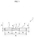
- Fig. 1 shows the shape of the fatigue test sample 1 used in the fatigue test.
- the fatigue test samples 1 were machined to a shape consisting of two cylindrical portions 2 and 4 connected by a portion 3 therebetween having a constricted shape.
- the cylindrical portions 2 and 4 each had smooth finished surfaces, and the constricted portion 3 was sanded with sandpaper in the axial direction to a precise finished surface.
- the total length W 1 of the fatigue test sample 1 was 90 mm, the length W 2 of the cylindrical portion 2 was 30 mm, the length W 3 of the constricted portion 3 was 30 mm, the length W 4 of the cylindrical portion 4 was 30 mm, the diameter D 1 of the cylindrical portions 2 and 4 and at both ends of the constricted portion 3 was 12 mm, and the diameter D 2 at the center of the constricted portion 3 was 6 mm.
- the constricted portion 3 had a radius of curvature R 1 of 39 mm and was constricted by the partial absence of material at the center thereof.
- the micro hole 11 had a shape consisting of a cylinder with a cone connected to the bottom thereof.
- the diameter D 3 of the micro hole 11 in the fatigue test sample 1 was 68 ⁇ m
- the depth H 1 to the apex of the cone was 68 ⁇ m
- the angle r 1 at the apex of the cone cross-section was 120°.
- the fatigue test was carried out with an Ono-type rotating bending fatigue tester (model H7) from Shimadzu Corporation. The test conditions were set to a load of 10 kgfm, a rotational speed of 3,000 rpm, and a stress ratio of -1. The fatigue test was begun by setting the initial stress to 440 MPa, and the fatigue test sample 1 was rotated 3 ⁇ 10 6 times. The stress test was repeated while increasing the stress in 20 MPa increments. The maximum value of the nominal stresses when the fatigue test sample 1 did not break even after 3 ⁇ 10 6 rotations was treated as the breaking stress. In other words, the value obtained by subtracting 20 MPa from the minimum value of the stress applied when the fatigue test sample 1 broke before being rotated 3 ⁇ 10 6 times was treated as the breaking stress.
- the martensite percentage was determined by Nital etching a cross-section of the test sample in the L (lengthwise) direction, observing a position at 1/4 of the depth in the cross-section, photographing it at a magnification of 100X, visually examining the micrograph and separating the martensite from other metal microstructures, and calculating the surface area percentage.
- the position at 1/4 depth in the test sample was examined at a magnification of 100X with an optical microscope and, setting the field of observation to 860 ⁇ m ⁇ 700 ⁇ m, the size of the prior austenite grains was measured. Setting the number of observation fields to five fields, the largest size of the prior austenite grains observed within the five fields was taken as the maximum grain size. In those examples in which "not measurable” is noted in the "maximum size of prior austenite grains” column in Table 2, this means that the prior austenite grains were too coarse, making it impossible to measure the maximum grain size.
- the position at 1/4 depth in the test sample was examined at a magnification of 8000X, and an observation field of 15 ⁇ m ⁇ 15 ⁇ m was examined by SEM.
- the Mn concentration in the examined cementite was measured by quantitative analysis using EDX with SEM.
- the number of observation fields was set to five fields, and the average value was determined.
- Table 2 shows the results for the value of X determined based on formula (1), the martensite percentage obtained by the above measurement, the maximum grain size, the Mn concentration in cementite, the tensile strength TS, the absorbed energy (vE) at room temperature and the endurance limit ratio.
- Examples 1 to 10 are all examples that satisfy the conditions of the invention.
- the Mn/Si ratios are 5.50 or more, and the metal microstructures are primarily martensite. Also, because the Mn/Si ratios were controlled to 5.50 or more, it was possible to hold down the maximum size of prior austenite grains to 100 ⁇ m or less.
- the tensile strength TS was 1050 MPa or more
- the absorbed energy (vE) at room temperature was 50 J or more
- the endurance limit ratio was 0.45 or more, enabling a high strength, high toughness and high fatigue strength to be achieved.
- Examples 2, 4 and 6 are examples in which the constituent composition was the same, with only the tempering temperature being varied in production.
- the tempering temperature was increased in this order and the tensile strength TS became lower, yet the absorbed energy at room temperature and the endurance limit ratio both showed rising trends in this order. A similar trend was observed also for Examples 3, 5 and 7.
- Comparative Examples 1 to 19 are examples in which the conditions specified for this invention were not all satisfied.
- Comparative Example 1 is an example in which the C content was low, the martensite percentage had decreased, and the value of X fell below 690. As a result, the tensile strength decreased.
- Comparative Example 2 is an example in which the C content was excessive. Here, the toughness and fatigue properties both decreased.
- Comparative Example 3 is an example in which the Si content was excessive. Here, the toughness and fatigue properties both worsened.
- Comparative Example 4 is an example in which the Mn content was excessive and the Mn concentration in cementite was high. As a result, the toughness and fatigue strength both decreased.
- Comparative Example 5 is an example in which the Ni content was low, the martensite percentage decreased, and the value of X fell below 690. As a result, the strength and toughness decreased.
- Comparative Example 6 is an example in which the Ni content was excessive. Here, the toughness decreased.
- Comparative Example 7 is an example in which the Cr content was low, the martensite percentage decreased, and the value of X fell below 690. As a result, the strength decreased.
- Comparative Example 8 is an example in which the Cr content was excessive. Here, the toughness decreased.
- Comparative Example 9 is an example in which the Mo content was low, the martensite percentage decreased, and the value of X fell below 690. As a result, the toughness decreased.
- Comparative Example 10 is an example in which the Mo content was excessive. Here, the toughness decreased.
- Comparative Example 11 is an example in which the V content was low, the martensite percentage decreased, and the value of X fell below 690. As a result, the strength decreased.
- Comparative Example 12 is an example in which the V content was excessive. Here, the toughness decreased.
- Comparative Example 13 is an example in which the A1 content was low, and Comparative Example 14 is an example in which the A1 content was excessive. Both had a decreased toughness.
- Comparative Examples 15 and 16 are each examples in which the Mn/Si ratio was small. Coarse prior austenite grains formed in the metal microstructure. The toughness and fatigue properties decreased.
- Comparative Example 17 is an example in which the Mn content in steel was low, as a result of which the Mn/Si ratio was low and the Mn concentration in cementite was low. Coarse prior austenite grains formed in the metal microstructure, as a result of which the toughness and fatigue properties decreased.
- Comparative Example 18 is an example that simulated Steel Type I in Patent Document 2.
- the Si content of 0.22% was excessive, and so the Mn/Si ratio was small. As a result, prior austenite grain coarsened and the fatigue properties decreased.
- Comparative Example 19 is an example that simulated Steel Type A in Patent Document 1.
- excessive N was included, the Mn content was low, and the Mn/Si ratio was small. As a result, the fatigue properties decreased.
- crankshaft of the invention is endowed with a high fatigue strength while also having increased strength and toughness.
- the crankshaft of the invention is suitable for use in, for example, diesel engines for ships, generators and the like.
Landscapes
- Engineering & Computer Science (AREA)
- Chemical & Material Sciences (AREA)
- Mechanical Engineering (AREA)
- Materials Engineering (AREA)
- Metallurgy (AREA)
- Organic Chemistry (AREA)
- General Engineering & Computer Science (AREA)
- Ocean & Marine Engineering (AREA)
- Shafts, Cranks, Connecting Bars, And Related Bearings (AREA)
- Heat Treatment Of Articles (AREA)
- Heat Treatment Of Steel (AREA)
Abstract
Description
- The present invention relates to a high-strength steel and to a crankshaft manufactured using the same. The crankshaft of the invention may be suitably used in, for example, the diesel engine of a ship or generator.
- Performance enhancements such as increased power, improved durability and greater compactness are sought in the diesel engines used in ships and generators. A need thus exists for high strength and high toughness in the forging steels that form the crankshafts used in diesel engines. Specifically, such forging steels are required to have a tensile strength of 1,000 MPa or more.
- NiCrMo-based high-strength steels have been developed as forging steels having a tensile strength of 1,000 MPa or more. For example,
Patent Document 1 discloses a high-strength, high-toughness forging steel used in crankshafts for diesel engines in ships and generators.Patent Document 2 discloses a high-strength forging steel that can be manufactured at a relatively low cost. - Forging steels for the crankshafts of such diesel engines are also required to have a high fatigue strength. Fatigue strength generally increases in proportion with the strength (hardness) of a material, but it is commonly known that the susceptibility to defects such as inclusions which are unavoidably present in materials becomes large at high strengths. Hence, in conventional forging steels, at tensile strengths of 1,000 MPa or more, it is not easy to obtain a forging steel having a high fatigue strength. Accordingly, there exists a desire for a high-strength steel that is endowed with high fatigue strength while also having increased strength and toughness.
-
- Patent Document 1:
Japanese Unexamined Patent Publication No. 2010-248540 - Patent Document 2:
Japanese Patent No. 4332070 - An object of this invention, which was arrived based on the above circumstances, is to provide a high-strength steel that is endowed with high fatigue strength while also having increased strength and toughness. A further object thereof is to provide a crankshaft manufactured using the high-strength steel.
- The high-strength steel of the present invention that was able to solve the above problem contains C (carbon): 0.30 mass % or more and 0.50 mass % or less, Si (silicon): more than 0 mass % and 0.15 mass % or less, Mn (manganese): 0.80 mass % or more and 1.5 mass % or less, Ni (nickel): 0.8 mass % or more and 2.4 mass % or less, Cr (chromium): 1.0 mass % or more and 3.0 mass % or less, Mo (molybdenum): 0.35 mass % or more and 0.70 mass % or less, V (vanadium): 0.10 mass % or more and 0.25 mass % or less, and Al (aluminum): 0.001 mass % or more and 0.040 mass % or less, with the balance being iron and inevitable impurities. The high-strength steel is mainly composed of martensite, wherein a Mn concentration in cementite is 0.90 mass % or more and 1.80 mass % or less, and a ratio of Mn content to Si content is 5.50 or more.
- The high-strength steel of the present invention, by having a steel composition set in the above ranges, a metal microstructure that is mainly composed of martensite and a ratio of Mn content to Si content set to 5.50 or more, is able to exhibit a high fatigue strength while also being endowed with increased strength and toughness. Specifically, the high-strength steel of the invention, by having a steel composition in the above ranges and a metal microstructure that is primarily martensite, can be conferred with increased hardenability, strength and toughness. Moreover, the high-strength steel of the invention, by having a ratio of Mn content to Si content set to 5.50 or more, is able to suppress the coarse prior austenite grains that form in portions of the metal microstructure, which is thought to enable the steel to exhibit a high fatigue strength.
- In the high-strength steel of the invention, the Mn concentration in cementite is 0.90 mass % or more and 1.80 mass % or less. By setting the Mn concentration in cementite within this range, suitably soft regions form around the cementite that is thought to be a source of fatigue crack initiation. These regions act to relieve fatigue crack-initiating stress and are thought to be capable of greatly improving the fatigue properties. As a result, a high-strength, high-toughness steel that exhibits higher fatigue strength is obtained.
- The high-strength steel of the invention preferably further contains Cu (copper) in the range of more than 0 mass % and 2 mass % or less. Moreover, in the high-strength steel of the invention, X defined by formula (1) below is 690 or more. The inventors have discovered that by setting X in formula (1) to a fixed value or more, the hardenability of large forgings can be improved. When the value of X is the lower limit indicated above or more, steel having an excellent hardenability and a higher strength can be obtained. In formula (1) below, C, Si, Mn, Ni, Cr, Mo and V are respectively values which represent the contents, in percent by mass, of C, Si, Mn, Ni, Cr, Mo and V.

- The crankshaft of the invention that was able to resolve the above problem can be obtained using the foregoing high-strength steel. Because it is obtained using this high-strength steel, the crankshaft of the invention has, as noted above, a high strength and toughness, and also has an excellent fatigue strength. The crankshaft of the invention is useful in, for example, diesel engines for ships, generators and the like.
- The high-strength steel of the invention exhibits a high fatigue strength while also having a high strength and toughness. Hence, the high-strength steel of the invention is useful as, for example, a material for diesel engine crankshafts to be used in ships, generators and the like.
-
-
Fig. 1 is side view showing the shape of a fatigue test sample used in a fatigue test. -
Fig. 2 is an enlarged cross-sectional view of a micro hole in a fatigue test sample used in a fatigue test. -
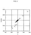
Fig. 3 is a graph showing the relationship between X calculated using formula (1) defined in the invention and the tensile strength TS. - Embodiments of the high-strength steel of the invention are described below.
- The metal microstructure of the high-strength steel in the invention is mainly composed of martensite. Here, "mainly composed of martensite" means that the ratio of martensite to the overall metal microstructure is 95% by surface area or more. The balance of the microstructure other than martensite is, for example, bainite and pearlite.
- The martensite percentage is preferably 98% by surface area or more, and more preferably 100% by surface area. By having the metal microstructure be primarily martensite, steel endowed with a high strength is obtained and the crankshaft strength can be increased.
- The balance of the microstructure other than martensite is 5% by surface area or less, preferably 2% by surface area or less, and most preferably 0% by surface area.
- The martensite percentage can be measured by, for example, using an optical microscope to photograph a cross-section of Nital-etched steel, visually examining the micrograph, separating the martensite from other metal microstructures in the micrograph, and calculating the percent surface area of the martensite relative to the entire metal microstructure.
- As mentioned above, the metal microstructure of the high-strength steel of the invention is mainly composed of martensite. This martensite contains cementite, the Mn concentration in the cementite being 0.90 mass % or more and 1.80 mass % or less. The lower limit of the Mn concentration in cementite is more preferably 1.0 mass %, and the upper limit of the Mn concentration is more preferably 1.5 mass %. When the Mn concentration in cementite is below this lower limit, stress that becomes a cause of fatigue crack initiation is thought to concentrate around the cementite, lowering the fatigue properties. Conversely, when the Mn concentration in the cementite exceeds the above upper limit, the region around cementite softens too much, lowering the fatigue properties. By setting the Mn concentration in the cementite within the above range, a suitably soft region forms around the cementite that is thought to be a source of fatigue crack initiation. This region presumably acts to relieve stresses that cause fatigue cracking, enabling the fatigue properties to be significantly improved. As a result, the invention enables high-strength, high-toughness steel having a higher fatigue strength to be obtained. The concentration of alloying elements in cementite can be analyzed by quantitative analysis using energy dispersive x-ray spectrometry (EDX) with a scanning electron microscope (SEM). EDX is a technique for carrying out elemental analysis and compositional analysis by detecting characteristic x-rays generated by electron beam irradiation and spectrally separating them by energy.
- The lower limit in the C content is 0.30 mass %, preferably 0.32 mass %, and more preferably 0.34 mass %. The upper limit in the C content is 0.50 mass %, preferably 0.48 mass %, and more preferably 0.46 mass %. When the C content is below this lower limit, sufficient hardenability and strength may not be achievable. On the other hand, when the C content exceeds this upper limit, the toughness may decrease excessively, promoting inverse V segregation in large ingots, and thus lowering the toughness and fatigue properties. By setting the C content in the above range, a suitable steel hardenability and strength can be achieved.
- The lower limit in the Si content is more than 0 mass %. The upper limit in the Si content is 0.15 mass %, preferably 0.12 mass %, and more preferably 0.1 mass %. At a Si content of 0 mass %, the hardenability of the steel is inadequate. On the other hand, at a Si content in excess of this upper limit, the toughness and fatigue strength may decrease. Also, when the Si content is higher, thus making the subsequently described Mn/Si ratio smaller, coarsening of the prior austenite grains is promoted, which may lower the toughness and fatigue strength. By setting the Si content in the above range, a suitable steel hardenability can be achieved.
- The lower limit in the Mn content is 0.80 mass %. The upper limit in the Mn content is 1.5 mass %, preferably 1.3 mass %, and more preferably 1 mass %. At a Mn content below this lower limit, sufficient strength and hardenability cannot be achieved, and it may not be possible suppress the coarsening of prior austenite grains. On the other hand, a Mn content in excess of this upper limit promotes inverse V segregation, which may lower the toughness. By setting the Mn content within this range, a suitable steel hardenability and strength can be achieved.
- The lower limit in the Ni content is 0.8 mass %, and preferably 1 mass %. The upper limit in the Ni content is 2.4 mass %, preferably 2 mass %, and more preferably 1.7 mass %. At a Ni content below this lower limit, the strength and toughness may decrease. On the other hand, a Ni content above this upper limit invites an excessive rise in strength, lowering the toughness. By setting the Ni content in this range, a suitable steel strength and toughness can be achieved.
- The lower limit in the Cr content is 1.0 mass %, and preferably 1.2 mass %. The upper limit in the Cr content is 3.0 mass %, preferably 2 mass %, and more preferably 1.7 mass %. At a Cr content below this lower limit, it may not be possible to achieve sufficient hardenability. On the other hand, a Cr content in excess of this upper limit promotes inverse V segregation, which may lower the toughness. By setting the Cr content is this range, a suitable steel hardenability and toughness can be achieved.
- The lower limit in the Mo content is 0.35 mass %, and preferably 0.45 mass %. The upper limit in the Mo content is 0.70 mass %, and preferably 0.6 mass %. At a Mo content below this lower limit, the hardenability and strength sometimes decrease, and inverse V segregation may be promoted. On the other hand, a Mo content above this upper limit promotes microsegregation within steel ingots. In addition, because Mo is a heavy element, weight segregation may arise, as a result of which the toughness sometimes decreases. By setting the Mo content in this range, a suitable steel hardenability, strength and toughness can be achieved.
- The lower limit in the V content is 0.10 mass %. The upper limit in the V content is 0.25 mass %, preferably 0.2 mass %, and more preferably 0.17 mass %. At a V content below this lower limit, the hardenability and strength are inadequate. On the other hand, because V has a low equilibrium partition coefficient, at a V content above this upper limit, microsegregation may arise. As a result, the toughness sometimes decreases. By setting the V content in this range, a suitable steel hardenability and strength can be achieved.
- The A1 content has a lower limit of 0.001 mass % and an upper limit of 0.040 mass %. At an A1 content below this lower limit, the A1 may be unable to effectively exhibit an oxygen content-lowering action as a deoxidizing element. As a result, a large amount of oxides may form, lowering the toughness. On the other hand, an A1 content in excess of this upper limit leads to a coarsening of the oxide, which may instead lower the toughness and fatigue properties. By setting the A1 content within this range, a steel oxygen content-lowering effect is suitably exhibited.
- The high-strength steel of the invention includes the above constituents, with the balance being iron and inevitable impurities. Examples of inevitable impurities include elements such as P (phosphorus), S (sulfur), N (nitrogen), Sn (tin), As (arsenic), Pb (lead) and Ti (titanium) that are inadvertently introduced depending on the conditions of the feedstock, materials, manufacturing equipment, etc.
- Of these inevitable impurities, the upper limit in the P content is preferably 0.15 mass %, more preferably 0.1 mass %, and even more preferably 0.05 mass %. When the P content exceeds this upper limit, intergranular fracture due to grain boundary segregation may be promoted.
- The upper limit in the S content is preferably 0.02 mass %, more preferably 0.01 mass %, even more preferably 0.005 mass %, and most preferably 0.0025 mass %. When the S content exceeds this upper limit, sulfide-based inclusions grow larger, which may lead to a deterioration in strength.
- The upper limit in the N content is preferably 0.008 mass %, more preferably 0.007 mass %, and even more preferably 0.0065 mass %. When the N content exceeds this upper limit, the toughness may deteriorate.
- The high-strength steel according to the invention has the constituent composition described above, although intentionally including also other alloying elements is effective as well. Depending on the type of alloying element thus included, the properties of the steel are further improved.
- For example, from the standpoint of enhancing hardenability, the high-strength steel of the invention preferably includes Cu. This effect is achieved by the addition of more than 0 mass % of Cu, with the lower limit of the Cu content being preferably 0.1 mass %. The upper limit of the Cu content is preferably 2 mass %. Conversely, when the Cu content exceeds this upper limit, the toughness may decrease. The Cu content is more preferably 1.5 mass % or less, and even more preferably 1 mass % or less.
- The ratio of Mn content to Si content (also denoted below as the "Mn/Si ratio") in the high-strength steel of the invention must be 5.50 or more. At a Mn/Si ratio below 5.50, coarse prior austenite grains form, which may lower the fatigue strength and toughness. In the invention, because the Mn/Si ratio is controlled to 5.50 or more, the formation of coarse prior austenite grains in the metal microstructure can be suppressed. The lower limit in the Mn/Si ratio is preferably 10, and more preferably 20. The upper limit of in the Mn/Si ratio is determined by the above-mentioned Si and Mn contents, and is preferably 30 or less, more preferably 28 or less, and even more preferably 25 or less.
- The upper limit in the grain size of the prior austenite grains is preferably 100 µm, more preferably 80 µm, and even more preferably 50 µm. By having a metal microstructure that is primarily martensite and setting the size of prior austenite grains in the metal microstructure to preferably the above-indicated upper limit or less, the concentration of stress acting on coarse areas of the prior austenite grains can be relieved, making it possible not only to increase the toughness but also to increase the fatigue properties. The lower limit in the size of prior austenite grains, although not particularly limited, is preferably 20 µm or more, more preferably 25 µm or more, and even more preferably 30 µm or more.
- As used herein, the "size of prior austenite grains" refers to the maximum diameter of prior austenite grains observed under an optical microscope at a magnification of 100X and in five fields. The size of prior austenite grains can be measured by the "Method for Visualizing Ferrite and Prior Austenite Crystal Grain Boundaries in Steel" described in JIS-G-0551.
- In the high-strength steel of the invention, the lower limit of the value X defined by formula (1) below is preferably 690, more preferably 695, and even more preferably 700. The inventors have discovered that, by setting X in formula (1) to this lower limit or above, the steel hardenability improves and the strength of large forgings such as crankshafts is enhanced. That is, when X is at or more than the above lower limit, the steel has an excellent hardenability and a higher strength. The upper limit of formula (1) is determined based on the constituent composition, and is preferably 1,000 or less, more preferably 900 or less, and even more preferably 800 or less. In formula (1) below, C, Si, Mn, Ni, Cr, Mo and V are respectively values representing the contents, in percent by mass, of C, Si, Mn, Ni, Cr, Mo and V.

- When X defined in the invention is larger, the tensile strength TS of forgings also become larger. This is explained while referring to
Fig. 3 , which was created by plotting, of the subsequently described examples, the results of those examples in which only the essential constituents were included and production was carried out at a tempering temperature of 600°C. InFig. 3 , filled-in squares (■) indicate the results of Examples 1 to 3, 8 and 9 in Table 2, and open diamonds (◊) indicate the results of Comparative Examples 1 to 17 and 19 in Table 2. It is apparent fromFig. 3 that when X is larger, the tensile strength TS also becomes larger in direct proportion thereto. - The tensile strength TS of the high-strength steel of the invention has a lower limit of preferably 1,050 MPa, and more preferably 1,100 MPa. At a tensile strength at or above this lower limit, the strength required of a crankshaft can be achieved. The strength can be evaluated by, for example, the tensile test set forth in JIS-Z-2241.
- The absorbed energy (vE) at room temperature of the high-strength steel according to the invention has a lower limit of preferably 50 J, and more preferably 80 J. When the absorbed energy (vE) is at or above this lower limit, the toughness required of a crankshaft can be achieved. The toughness is evaluated by measuring the absorbed energy (vE) at room temperature in, for example, the Charpy impact test based on JIS-Z-2242.
- The endurance limit ratio in the high-strength steel of the invention has a lower limit of preferably 0.45, more preferably 0.5, even more preferably 0.52, and most preferably 0.54. When the endurance limit ratio is at or above this lower limit, the fatigue strength required of a crankshaft can be achieved. The endurance limit ratio is determined by dividing the breaking stress measured in a fatigue test by the maximum stress in a tensile test. The breaking stress can be measured by, for example, the rotating bending fatigue test of metal materials according to JIS-Z-2274.
- The method of producing the high-strength steel of the invention is not particularly limited, and may involve, in the usual manner: ingot formation → component adjustment → casting. First, steel having given chemical constituents is formed into ingots using a high-frequency melting furnace, electric furnace, converter or the like. Next, component adjustment is carried out by vacuum refining or the like to remove impurity elements such as S and gaseous components such as oxygen, after which the steel is cast into cast ingots. In particular, by regulating the Mn/Si ratio to 5.50 or more, the maximum size of coarse prior austenite grains can be suitably controlled, enabling the formation of coarse grains to be suppressed. Also, the Mn concentration in cementite can be adjusted by regulating the amount of Mn in the steel. The casting method is not particularly limited. In the case of steel intended for large forgings, use is primarily made of ingot casting, but a continuous casting process may be used for relatively small steel forgings.
- The invention also encompasses a crankshaft obtained using this steel. The method of producing the crankshaft is not particularly limited. For example, production may be carried out by: heating the steel → material forging → removing by in-process inspection defective product after material forging, then heating and forging into a crankshaft shape → homogenization by heat treatment → hardening by quenching and tempering treatment → and finish machining.
- In these steps, an ordinary method may be used without particular limitation to forge the steel into a crankshaft shape. Examples include free-forging in which the steel is forged into a monolithic block that includes the crank arm and the crank pin, and then is finished to the crankshaft shape by gas cutting and machining; and R.R. forging and T.R. forging in which the steel is forged into the shape of a crankshaft. By using in particular the latter forging techniques, that is, R.R. forging and T.R. forging, the shaft surface layer side of the crankshaft can be made of steel having a high degree of cleanliness, enabling a crankshaft of excellent strength and fatigue properties to be easily obtained.
- In these steps, homogenization by heat treatment is sometimes called austenitizing treatment. Austenitizing treatment preferably involves, for example, heating in a temperature range of from room temperature to between 820 and 950°C at an average ramp-up rate of 30 to 100°C/hr, and holding the temperature at between 820 and 950°C for 3 to 20 hours.
- After such holding, quenching and tempering are carried out as described above. Quenching preferably involves cooling in a temperature range of, for example, 870°C to 500°C at an average cooling rate of 5 to 50°C/min. Tempering preferably involves heating in a temperature range of 550°C to 680°C, holding the temperature in this range for 5 to 20 hours, and then cooling. At a high tempering temperature, the tensile strength tends to decrease, but the toughness and fatigue properties can be improved.
- This application claims priority from
Japanese Patent Application No. 2013-176113 - The invention is described more fully below by way of examples, but is not limited by these examples.
- A feedstock having the constituent composition shown in Table 1, with the balance being iron and inevitable impurities, was ingoted in a high-frequency furnace and cast into a 50 kg steel ingot having a diameter of 150 mm and a length of 323 mm. The head portion of the resulting steel ingot was cut away and the ingot was heated at 1,230°C for 10 hours, following which material forging was carried out in which a free-forging press was used to compress the ingot to a height ratio of 1/2 from a pre-compression height of 320 mm. Next, the steel ingot centerline was rotated 90° and forging was carried out, extending the ingot to dimensions of 90 mm × 90 mm × 450 mm, after which the ingot was left to cool in open air. Once the ingot had cooled down to room temperature, austenitizing treatment was carried out using a small-scale simulation furnace. Austenitizing treatment involved raising the temperature from room temperature to 870°C at an average ramp-up rate of 50°C/hr, then holding the temperature for 3 hours. After holding, quenching was carried out by cooling the ingot through a temperature range of 870°C to 500°C at an average cooling rate of 50°C/min. After quenching, the ingot was tempered by being held at 600°C for 13 hours, following which the furnace was cooled. Each of the test samples was prepared in this way. In Table 1, a dash (-) indicates a value below the limit of measurement.
- Aside from setting the heating time at 1230°C to 5 hours and the tempering temperature to 580°C, test samples were prepared in the same way as in Example 1.
- Aside from setting the heating time at 1230°C to 5 hours and the tempering temperature to 560°C, test samples were prepared in the same way as in Example 1.
[Table 1] Composition contents (mass %) Mn/Si C Si Mn P S Cu Ni Cr Mo V Al N Example 1 0.35 0.05 0.80 0.004 0.003 - 1.6 1.6 0.50 0.15 0.0250 0.0050 16.00 Example 2 0.35 0.05 1.20 0.004 0.002 - 1.6 1.6 0.50 0.15 0.0250 0.0051 24.00 Example 3 0.35 0.05 0.80 0.004 0.003 - 2.0 1.6 0.50 0.15 0.0250 0.0045 16.00 Example 4 0.35 0.05 1.20 0.004 0.002 - 1.6 1.6 0.50 0.15 0.0250 0.0060 24.00 Example 5 0.35 0.05 0.80 0.004 0.003 - 2.0 1.6 0.50 0.15 0.0250 0.0060 16.00 Example 6 0.35 0.05 1.20 0.004 0.002 - 1.6 1.6 0.50 0.15 0.0250 0.0060 24.00 Example 7 0.35 0.05 0.80 0.004 0.003 - 2.0 1.6 0.50 0.15 0.0250 0.0060 16.00 Example 8 0.35 0.15 0.84 0.004 0.003 - 2.0 1.6 0.50 0.15 0.0250 0.0048 5.60 Example 9 0.35 0.10 0.80 0.004 0.003 - 2.0 1.6 0.50 0.15 0.0250 0.0050 8.00 Example 10 0.35 0.05 0.80 0.004 0.003 0.90 2.0 1.6 0.50 0.15 0.0250 0.0060 16.00 Comparative Example 1 0.28 0.05 0.80 0.003 0.003 - 1.6 1.6 0.51 0.15 0.0250 0.0048 16.00 Comparative Example 2 0.52 0.05 0.81 0.004 0.003 - 1.6 1.6 0.50 0.16 0.0260 0.0051 16.20 Comparative Example 3 0.34 0.16 0.90 0.004 0.002 - 1.6 1.6 0.49 0.15 0.0250 0.0049 5.63 Comparative Example 4 0.35 0.10 1.60 0.004 0.003 - 1.6 1.6 0.50 0.16 0.0250 0.0060 16.00 Comparative Example 5 0.36 0.04 0.80 0.004 0.003 - 0.7 1.6 0.50 0.15 0.0250 0.0050 20.00 Comparative Example 6 0.35 0.05 0.81 0.003 0.002 - 2.6 1.6 0.50 0.15 0.0230 0.0050 16.20 Comparative Example 7 0.36 0.06 0.80 0.004 0.003 - 1.6 0.9 0.48 0.14 0.0250 0.0048 13.33 Comparative Example 8 0.35 0.05 0.82 0.004 0.003 - 1.6 3.2 0.50 0.15 0.0270 0.0050 16.40 Comparative Example 9 0.36 0.04 0.80 0.003 0.002 - 1.6 1.6 0.33 0.15 0.0250 0.0050 20.00 Comparative Example 10 0.35 0.05 0.81 0.004 0.003 - 1.6 1.6 0.72 0.14 0.0220 0.0048 16.20 Comparative Example 11 0.33 0.06 0.80 0.004 0.002 - 1.6 1.6 0.50 0.08 0.0250 0.0053 13.33 Comparative Example 12 0.35 0.05 0.83 0.003 0.003 - 1.6 1.6 0.51 0.27 0.0250 0.0051 16.60 Comparative Example 13 0.35 0.05 0.80 0.004 0.002 - 1.6 1.6 0.50 0.15 0.0004 0.0052 16.00 Comparative Example 14 0.35 0.05 0.80 0.004 0.003 - 1.6 1.6 0.50 0.14 0.0430 0.0051 16.00 Comparative Example 15 0.34 0.15 0.82 0.004 0.003 - 1.6 1.6 0.50 0.15 0.0250 0.0051 5.47 Comparative Example 16 0.35 0.15 0.80 0.004 0.003 - 1.6 1.6 0.50 0.15 0.0250 0.0049 5.33 Comparative Example 17 0.35 0.15 0.77 0.004 0.003 - 1.6 1.6 0.50 0.15 0.0250 0.0050 5.13 Comparative Example 18 0.34 0.22 0.98 0.007 0.003 0.04 1.6 1.6 0.49 0.16 0.0200 0.0050 4.45 Comparative Example 19 0.35 0.08 0.35 0.015 0.003 - 3.0 1.6 0.45 0.10 0.0250 0.0050 4.38 - The tensile strength TS of the test samples was measured by a tensile test. The tensile test was carried out based on JIS-Z-2241. The test sample shape was that of the No. 14 test sample in JIS-Z-2201, the dimensions being 6 mm (diameter) x G. 30 mm. Here, "G. 30 mm" means that the length of the parallel portion is 30 mm.
- The absorbed energy (vE) at room temperature of the test sample was measured by the Charpy impact test, and the toughness was evaluated. The Charpy impact test was carried out at room temperature based on JIS-Z-2242. As for the test sample, the 2 mm V notch described in JIS-Z-2202 was used.
- Evaluation of the fatigue strength was carried out by the following fatigue test using the endurance limit ratio (breaking stress measured in fatigue test/maximum stress in tensile test) as the indicator.
Fig. 1 shows the shape of thefatigue test sample 1 used in the fatigue test. Thefatigue test samples 1 were machined to a shape consisting of twocylindrical portions portion 3 therebetween having a constricted shape. Thecylindrical portions constricted portion 3 was sanded with sandpaper in the axial direction to a precise finished surface. The total length W1 of thefatigue test sample 1 was 90 mm, the length W2 of thecylindrical portion 2 was 30 mm, the length W3 of theconstricted portion 3 was 30 mm, the length W4 of thecylindrical portion 4 was 30 mm, the diameter D1 of thecylindrical portions constricted portion 3 was 12 mm, and the diameter D2 at the center of theconstricted portion 3 was 6 mm. Theconstricted portion 3 had a radius of curvature R1 of 39 mm and was constricted by the partial absence of material at the center thereof. In thefatigue test sample 1, amicro hole 11 having the cross-sectional shape shown inFig. 2 was formed perpendicular to the surface with a drill as an artificial defect simulating an inclusion at acenter position 5 on thefatigue test sample 1. Themicro hole 11 had a shape consisting of a cylinder with a cone connected to the bottom thereof. The diameter D3 of themicro hole 11 in thefatigue test sample 1 was 68 µm, the depth H1 to the apex of the cone was 68 µm, and the angle r1 at the apex of the cone cross-section was 120°. - The fatigue test was carried out with an Ono-type rotating bending fatigue tester (model H7) from Shimadzu Corporation. The test conditions were set to a load of 10 kgfm, a rotational speed of 3,000 rpm, and a stress ratio of -1. The fatigue test was begun by setting the initial stress to 440 MPa, and the
fatigue test sample 1 was rotated 3×10⁶ times. The stress test was repeated while increasing the stress in 20 MPa increments. The maximum value of the nominal stresses when thefatigue test sample 1 did not break even after 3×10⁶ rotations was treated as the breaking stress. In other words, the value obtained by subtracting 20 MPa from the minimum value of the stress applied when thefatigue test sample 1 broke before being rotated 3×10⁶ times was treated as the breaking stress. - The martensite percentage was determined by Nital etching a cross-section of the test sample in the L (lengthwise) direction, observing a position at 1/4 of the depth in the cross-section, photographing it at a magnification of 100X, visually examining the micrograph and separating the martensite from other metal microstructures, and calculating the surface area percentage.
- The position at 1/4 depth in the test sample was examined at a magnification of 100X with an optical microscope and, setting the field of observation to 860 µm × 700 µm, the size of the prior austenite grains was measured. Setting the number of observation fields to five fields, the largest size of the prior austenite grains observed within the five fields was taken as the maximum grain size. In those examples in which "not measurable" is noted in the "maximum size of prior austenite grains" column in Table 2, this means that the prior austenite grains were too coarse, making it impossible to measure the maximum grain size.
- The position at 1/4 depth in the test sample was examined at a magnification of 8000X, and an observation field of 15 µm × 15 µm was examined by SEM. The Mn concentration in the examined cementite was measured by quantitative analysis using EDX with SEM. The number of observation fields was set to five fields, and the average value was determined.
- Table 2 shows the results for the value of X determined based on formula (1), the martensite percentage obtained by the above measurement, the maximum grain size, the Mn concentration in cementite, the tensile strength TS, the absorbed energy (vE) at room temperature and the endurance limit ratio.
[Table 2] X Martensite (surface area %) Maximum size of prior austenite grains (µm) Mn concentration in cementite (mass %) TS (MPa) vE at room temperature (J) Endurance limit ratio Example 1 684 98 40 0.92 1083 88 0.54 Example 2 699 100 50 1.38 1098 87 0.53 Example 3 705 100 45 0.92 1103 86 0.54 Example 4 699 100 50 1.36 1215 78 0.48 Example 5 705 100 45 0.93 1228 62 0.48 Example 6 699 100 50 1.35 1305 78 0.46 Example 7 705 100 45 0.92 1310 62 0.46 Example 8 699 100 90 0.97 1097 87 0.54 Example 9 701 100 75 0.92 1099 86 0.52 Example 10 705 100 45 0.93 1245 61 0.48 Comparative Example 1 613 85 not measurable 0.92 951 100 0.50 Comparative Example 2 868 100 not measurable 0.93 1266 23 0.44 Comparative Example 3 669 97 not measurable 1.04 1067 25 0.41 Comparative Example 4 719 100 not measurable 1.84 1118 40 0.39 Comparative Example 5 650 89 not measurable 0.92 987 27 0.50 Comparative Example 6 735 100 not measurable 0.93 1134 45 0.48 Comparative Example 7 662 91 not measurable 0.92 1011 94 0.50 Comparative Example 8 736 100 not measurable 0.94 1134 27 0.47 Comparative Example 9 681 92 not measurable 0.92 1019 93 0.49 Comparative Example 10 693 99 not measurable 0.90 1092 31 0.46 Comparative Example 11 604 87 not measurable 0.92 974 98 0.49 Comparative Example 12 787 100 not measurable 0.95 1185 24 0.45 Comparative Example 13 684 98 not measurable 0.92 1083 28 0.47 Comparative Example 14 676 97 not measurable 0.92 1075 36 0.48 Comparative Example 15 667 97 400 0.94 1066 24 0.42 Comparative Example 16 677 98 450 0.92 1075 25 0.43 Comparative Example 17 676 97 450 0.89 1074 21 0.40 Comparative Example 18 676 97 500 1.13 1073 90 0.43 Comparative Example 19 690 99 105 0.38 1088 102 0.42 - Examples 1 to 10 are all examples that satisfy the conditions of the invention. Along with having specific compositions, the Mn/Si ratios are 5.50 or more, and the metal microstructures are primarily martensite. Also, because the Mn/Si ratios were controlled to 5.50 or more, it was possible to hold down the maximum size of prior austenite grains to 100 µm or less. As a result, in all of these examples, the tensile strength TS was 1050 MPa or more, the absorbed energy (vE) at room temperature was 50 J or more, and the endurance limit ratio was 0.45 or more, enabling a high strength, high toughness and high fatigue strength to be achieved.
- Of these examples, in Examples 2 to 10 in particular, because the value X expressed in formula (1) is controlled to 690 or more, the tensile strength TS was higher than in Example 1 in which the value X was less than 690.
- Also, of the above examples, Examples 2, 4 and 6 are examples in which the constituent composition was the same, with only the tempering temperature being varied in production. In Examples 2, 4 and 6, the tempering temperature was increased in this order and the tensile strength TS became lower, yet the absorbed energy at room temperature and the endurance limit ratio both showed rising trends in this order. A similar trend was observed also for Examples 3, 5 and 7.
- By contrast, Comparative Examples 1 to 19 are examples in which the conditions specified for this invention were not all satisfied.
- Comparative Example 1 is an example in which the C content was low, the martensite percentage had decreased, and the value of X fell below 690. As a result, the tensile strength decreased.
- Comparative Example 2 is an example in which the C content was excessive. Here, the toughness and fatigue properties both decreased.
- Comparative Example 3 is an example in which the Si content was excessive. Here, the toughness and fatigue properties both worsened.
- Comparative Example 4 is an example in which the Mn content was excessive and the Mn concentration in cementite was high. As a result, the toughness and fatigue strength both decreased.
- Comparative Example 5 is an example in which the Ni content was low, the martensite percentage decreased, and the value of X fell below 690. As a result, the strength and toughness decreased.
- Comparative Example 6 is an example in which the Ni content was excessive. Here, the toughness decreased.
- Comparative Example 7 is an example in which the Cr content was low, the martensite percentage decreased, and the value of X fell below 690. As a result, the strength decreased.
- Comparative Example 8 is an example in which the Cr content was excessive. Here, the toughness decreased.
- Comparative Example 9 is an example in which the Mo content was low, the martensite percentage decreased, and the value of X fell below 690. As a result, the toughness decreased.
- Comparative Example 10 is an example in which the Mo content was excessive. Here, the toughness decreased.
- Comparative Example 11 is an example in which the V content was low, the martensite percentage decreased, and the value of X fell below 690. As a result, the strength decreased.
- Comparative Example 12 is an example in which the V content was excessive. Here, the toughness decreased.
- Comparative Example 13 is an example in which the A1 content was low, and Comparative Example 14 is an example in which the A1 content was excessive. Both had a decreased toughness.
- Comparative Examples 15 and 16 are each examples in which the Mn/Si ratio was small. Coarse prior austenite grains formed in the metal microstructure. The toughness and fatigue properties decreased.
- Comparative Example 17 is an example in which the Mn content in steel was low, as a result of which the Mn/Si ratio was low and the Mn concentration in cementite was low. Coarse prior austenite grains formed in the metal microstructure, as a result of which the toughness and fatigue properties decreased.
- Comparative Example 18 is an example that simulated Steel Type I in
Patent Document 2. In this example, the Si content of 0.22% was excessive, and so the Mn/Si ratio was small. As a result, prior austenite grain coarsened and the fatigue properties decreased. - Comparative Example 19 is an example that simulated Steel Type A in
Patent Document 1. In this example, excessive N was included, the Mn content was low, and the Mn/Si ratio was small. As a result, the fatigue properties decreased. - The high-strength steel of the invention and the crankshaft of the invention manufactured using this high-strength steel are endowed with a high fatigue strength while also having increased strength and toughness. Hence, the crankshaft of the invention is suitable for use in, for example, diesel engines for ships, generators and the like.
-
- 1
- Fatigue test sample
- 2
- Cylindrical portion
- 3
- Constricted portion
- 4
- Cylindrical portion
- 5
- Center position
- 11
- Micro hole
Claims (4)
- A high-strength steel comprising:C: 0.30 mass % or more and 0.50 mass % or less;Si: more than 0 mass % and 0.15 mass % or less;Mn: 0.80 mass % or more and 1.5 mass % or less;Ni: 0.8 mass % or more and 2.4 mass % or less;Cr: 1.0 mass % or more and 3.0 mass % or less;Mo: 0.35 mass % or more and 0.70 mass % or less;V: 0.10 mass % or more and 0.25 mass % or less; andAl: 0.001 mass % or more and 0.040 mass % or less,with the balance being iron and inevitable impurities,wherein the high-strength steel is mainly composed of martensite,a Mn concentration in cementite is 0.90 mass % or more and 1.80 mass % or less, anda ratio of Mn content to Si content is 5.50 or more.
- The high-strength steel according to claim 1, further comprising Cu in the range of more than 0 mass % and 2 mass % or less.
- The high-strength steel according to claim 1 or 2, wherein X defined by formula (1) below is 690 or more:

- A crankshaft manufactured using the high-strength steel according to claim 1.
Applications Claiming Priority (2)
| Application Number | Priority Date | Filing Date | Title |
|---|---|---|---|
| JP2013176113A JP6100129B2 (en) | 2013-08-27 | 2013-08-27 | High-strength steel and crankshaft for marine or generator diesel engines |
| PCT/JP2014/072278 WO2015029993A1 (en) | 2013-08-27 | 2014-08-26 | High-strength steel, and crankshaft manufactured using said high-strength steel |
Publications (2)
| Publication Number | Publication Date |
|---|---|
| EP3040438A1 true EP3040438A1 (en) | 2016-07-06 |
| EP3040438A4 EP3040438A4 (en) | 2017-05-17 |
Family
ID=52586548
Family Applications (1)
| Application Number | Title | Priority Date | Filing Date |
|---|---|---|---|
| EP14841312.3A Withdrawn EP3040438A4 (en) | 2013-08-27 | 2014-08-26 | High-strength steel, and crankshaft manufactured using said high-strength steel |
Country Status (5)
| Country | Link |
|---|---|
| EP (1) | EP3040438A4 (en) |
| JP (1) | JP6100129B2 (en) |
| KR (1) | KR101800563B1 (en) |
| CN (1) | CN105473754B (en) |
| WO (1) | WO2015029993A1 (en) |
Cited By (1)
| Publication number | Priority date | Publication date | Assignee | Title |
|---|---|---|---|---|
| EP3401412A4 (en) * | 2016-01-08 | 2019-07-17 | Kabushiki Kaisha Kobe Seiko Sho (Kobe Steel, Ltd.) | Large crankshaft |
Families Citing this family (1)
| Publication number | Priority date | Publication date | Assignee | Title |
|---|---|---|---|---|
| JP7823518B2 (en) * | 2022-07-20 | 2026-03-04 | 株式会社プロテリアル | Manufacturing method of chromium-molybdenum vanadium steel |
Family Cites Families (14)
| Publication number | Priority date | Publication date | Assignee | Title |
|---|---|---|---|---|
| JPH0688163A (en) * | 1991-11-05 | 1994-03-29 | Sanyo Special Steel Co Ltd | Hot work tool steel |
| US5496516A (en) * | 1994-04-04 | 1996-03-05 | A. Finkl & Sons Co. | Dual purpose steel and products produced therefrom |
| JPH08134547A (en) * | 1994-11-04 | 1996-05-28 | Daido Steel Co Ltd | Hollow steel tool manufacturing method |
| JP2002080951A (en) * | 2000-09-07 | 2002-03-22 | Kobe Steel Ltd | Method for producing galvannealed steel sheet |
| JP4332070B2 (en) | 2004-06-01 | 2009-09-16 | 株式会社神戸製鋼所 | High strength steel and crankshaft for large steel products |
| JP4436225B2 (en) * | 2004-10-08 | 2010-03-24 | 新日本製鐵株式会社 | High-strength mechanical parts with excellent fatigue characteristics and methods for improving the fatigue characteristics |
| CN100516268C (en) * | 2004-09-17 | 2009-07-22 | 新日本制铁株式会社 | High strength machine parts and shaft excellent in fatigue characteristics, and method for improving fatigue characteristics thereof |
| JP5089267B2 (en) * | 2007-06-26 | 2012-12-05 | 株式会社神戸製鋼所 | Integrated crankshaft |
| EP1978124B1 (en) * | 2007-04-05 | 2014-10-22 | Kabushiki Kaisha Kobe Seiko Sho | Forging steel, forging and crankshaft |
| JP2009173961A (en) * | 2008-01-22 | 2009-08-06 | Kobe Steel Ltd | Steel for forging and forged product obtained by using the same |
| JP4964211B2 (en) * | 2008-09-30 | 2012-06-27 | 株式会社神戸製鋼所 | Forged product and crankshaft manufactured from the forged product |
| CN101492790A (en) * | 2009-01-19 | 2009-07-29 | 中国北车集团大连机车车辆有限公司 | High-power diesel engine crank axle |
| JP5319374B2 (en) | 2009-04-10 | 2013-10-16 | 株式会社神戸製鋼所 | Integrated crankshaft and manufacturing method thereof |
| JP5747243B2 (en) * | 2009-10-16 | 2015-07-08 | 国立研究開発法人物質・材料研究機構 | Warm working steel |
-
2013
- 2013-08-27 JP JP2013176113A patent/JP6100129B2/en not_active Expired - Fee Related
-
2014
- 2014-08-26 CN CN201480046688.5A patent/CN105473754B/en not_active Expired - Fee Related
- 2014-08-26 EP EP14841312.3A patent/EP3040438A4/en not_active Withdrawn
- 2014-08-26 WO PCT/JP2014/072278 patent/WO2015029993A1/en not_active Ceased
- 2014-08-26 KR KR1020167006532A patent/KR101800563B1/en not_active Expired - Fee Related
Cited By (1)
| Publication number | Priority date | Publication date | Assignee | Title |
|---|---|---|---|---|
| EP3401412A4 (en) * | 2016-01-08 | 2019-07-17 | Kabushiki Kaisha Kobe Seiko Sho (Kobe Steel, Ltd.) | Large crankshaft |
Also Published As
| Publication number | Publication date |
|---|---|
| JP6100129B2 (en) | 2017-03-22 |
| JP2015045049A (en) | 2015-03-12 |
| WO2015029993A1 (en) | 2015-03-05 |
| EP3040438A4 (en) | 2017-05-17 |
| KR101800563B1 (en) | 2017-11-22 |
| CN105473754B (en) | 2017-09-22 |
| KR20160043040A (en) | 2016-04-20 |
| CN105473754A (en) | 2016-04-06 |
Similar Documents
| Publication | Publication Date | Title |
|---|---|---|
| KR102027874B1 (en) | Steel wire and non-machined parts for non-machined parts | |
| KR20140073506A (en) | Ingot for bearing and production process | |
| JP6561816B2 (en) | Crankshaft and manufacturing method thereof | |
| KR20190028781A (en) | High frequency quenching steel | |
| KR20190028782A (en) | High frequency quenching steel | |
| KR20190031278A (en) | High frequency quenching steel | |
| KR20190021379A (en) | High strength steel wire | |
| JP6614393B2 (en) | Non-tempered steel bar | |
| KR20190028492A (en) | High frequency quenching steel | |
| KR20190028757A (en) | High frequency quenching steel | |
| KR101547015B1 (en) | High strength large steel forging | |
| JP2017128795A (en) | Forging steel and large forged steel products | |
| WO2015093179A1 (en) | High-strength steel for steel forgings, and steel forging | |
| WO2017126695A1 (en) | Steel wire for non-heat treated machine part, and non-heat treated machine part | |
| JP6729686B2 (en) | Non-heat treated steel for induction hardening | |
| KR101775816B1 (en) | Large-sized forging steel and large-sized forged part | |
| CN105473754B (en) | High-strength steel, and a crankshaft using the above-mentioned high-strength steel | |
| EP3805418B1 (en) | Steel material for steel piston | |
| JP7270420B2 (en) | Hot forged non-heat treated parts, manufacturing method thereof, and steel materials for hot forged non-heat treated parts | |
| WO2020194653A1 (en) | Steel to be subjected to induction hardening | |
| JP7127999B2 (en) | Steel for forgings, forged steel crank throws and forged journals for assembled crankshafts | |
| JP2022130746A (en) | Non-heat-treated forged component and non-heat-treated forging steel | |
| WO2020202472A1 (en) | Nitrided component | |
| JP5755965B2 (en) | Steel for connecting rod and connecting rod | |
| WO2017126407A1 (en) | Forging steel and large forged steel product |
Legal Events
| Date | Code | Title | Description |
|---|---|---|---|
| PUAI | Public reference made under article 153(3) epc to a published international application that has entered the european phase |
Free format text: ORIGINAL CODE: 0009012 |
|
| 17P | Request for examination filed |
Effective date: 20160211 |
|
| AK | Designated contracting states |
Kind code of ref document: A1 Designated state(s): AL AT BE BG CH CY CZ DE DK EE ES FI FR GB GR HR HU IE IS IT LI LT LU LV MC MK MT NL NO PL PT RO RS SE SI SK SM TR |
|
| AX | Request for extension of the european patent |
Extension state: BA ME |
|
| DAX | Request for extension of the european patent (deleted) | ||
| A4 | Supplementary search report drawn up and despatched |
Effective date: 20170418 |
|
| RIC1 | Information provided on ipc code assigned before grant |
Ipc: C22C 38/00 20060101AFI20170408BHEP Ipc: F16C 3/08 20060101ALI20170408BHEP Ipc: C22C 38/46 20060101ALI20170408BHEP Ipc: F16C 3/06 20060101ALI20170408BHEP |
|
| 17Q | First examination report despatched |
Effective date: 20180302 |
|
| GRAP | Despatch of communication of intention to grant a patent |
Free format text: ORIGINAL CODE: EPIDOSNIGR1 |
|
| INTG | Intention to grant announced |
Effective date: 20180629 |
|
| GRAJ | Information related to disapproval of communication of intention to grant by the applicant or resumption of examination proceedings by the epo deleted |
Free format text: ORIGINAL CODE: EPIDOSDIGR1 |
|
| GRAP | Despatch of communication of intention to grant a patent |
Free format text: ORIGINAL CODE: EPIDOSNIGR1 |
|
| INTC | Intention to grant announced (deleted) | ||
| INTG | Intention to grant announced |
Effective date: 20181119 |
|
| STAA | Information on the status of an ep patent application or granted ep patent |
Free format text: STATUS: THE APPLICATION IS DEEMED TO BE WITHDRAWN |
|
| 18D | Application deemed to be withdrawn |
Effective date: 20190330 |