EP3040278A1 - Canister system for air separation module - Google Patents
Canister system for air separation module Download PDFInfo
- Publication number
- EP3040278A1 EP3040278A1 EP15203240.5A EP15203240A EP3040278A1 EP 3040278 A1 EP3040278 A1 EP 3040278A1 EP 15203240 A EP15203240 A EP 15203240A EP 3040278 A1 EP3040278 A1 EP 3040278A1
- Authority
- EP
- European Patent Office
- Prior art keywords
- canister
- end cap
- air separation
- separation module
- transfer tube
- Prior art date
- Legal status (The legal status is an assumption and is not a legal conclusion. Google has not performed a legal analysis and makes no representation as to the accuracy of the status listed.)
- Granted
Links
Images



Classifications
-
- B—PERFORMING OPERATIONS; TRANSPORTING
- B01—PHYSICAL OR CHEMICAL PROCESSES OR APPARATUS IN GENERAL
- B01J—CHEMICAL OR PHYSICAL PROCESSES, e.g. CATALYSIS OR COLLOID CHEMISTRY; THEIR RELEVANT APPARATUS
- B01J19/00—Chemical, physical or physico-chemical processes in general; Their relevant apparatus
- B01J19/24—Stationary reactors without moving elements inside
-
- B—PERFORMING OPERATIONS; TRANSPORTING
- B64—AIRCRAFT; AVIATION; COSMONAUTICS
- B64D—EQUIPMENT FOR FITTING IN OR TO AIRCRAFT; FLIGHT SUITS; PARACHUTES; ARRANGEMENT OR MOUNTING OF POWER PLANTS OR PROPULSION TRANSMISSIONS IN AIRCRAFT
- B64D37/00—Arrangements in connection with fuel supply for power plant
- B64D37/32—Safety measures not otherwise provided for, e.g. preventing explosive conditions
-
- B—PERFORMING OPERATIONS; TRANSPORTING
- B01—PHYSICAL OR CHEMICAL PROCESSES OR APPARATUS IN GENERAL
- B01J—CHEMICAL OR PHYSICAL PROCESSES, e.g. CATALYSIS OR COLLOID CHEMISTRY; THEIR RELEVANT APPARATUS
- B01J2219/00—Chemical, physical or physico-chemical processes in general; Their relevant apparatus
- B01J2219/00049—Controlling or regulating processes
- B01J2219/00245—Avoiding undesirable reactions or side-effects
-
- B—PERFORMING OPERATIONS; TRANSPORTING
- B01—PHYSICAL OR CHEMICAL PROCESSES OR APPARATUS IN GENERAL
- B01J—CHEMICAL OR PHYSICAL PROCESSES, e.g. CATALYSIS OR COLLOID CHEMISTRY; THEIR RELEVANT APPARATUS
- B01J2219/00—Chemical, physical or physico-chemical processes in general; Their relevant apparatus
- B01J2219/24—Stationary reactors without moving elements inside
-
- B—PERFORMING OPERATIONS; TRANSPORTING
- B64—AIRCRAFT; AVIATION; COSMONAUTICS
- B64D—EQUIPMENT FOR FITTING IN OR TO AIRCRAFT; FLIGHT SUITS; PARACHUTES; ARRANGEMENT OR MOUNTING OF POWER PLANTS OR PROPULSION TRANSMISSIONS IN AIRCRAFT
- B64D13/00—Arrangements or adaptations of air-treatment apparatus for aircraft crew or passengers, or freight space
- B64D13/06—Arrangements or adaptations of air-treatment apparatus for aircraft crew or passengers, or freight space the air being conditioned
- B64D2013/0603—Environmental Control Systems
- B64D2013/0677—Environmental Control Systems comprising on board oxygen generator systems
Definitions
- a method of removing and installing an air separation module canister in an air separation module includes engaging a first end of a canister to a first end cap, engaging a second end of the canister to a second end cap, the second end of the canister including a collar defining a first position and a second position, moving the collar on the second end of the canister from the second position to the first position to engage the collar with the second end cap, and locking the canister in an engaged position with a locking mechanism between the first end cap and the second end cap.
- FIGS. 1A and 1B may be possible without departing from the scope of the invention.
- FIGS. 1A and 1B may be possible without departing from the scope of the invention.
- FIGS. 1A and 1B may be possible without departing from the scope of the invention.
- FIGS. 1A and 1B may be possible without departing from the scope of the invention.
- FIGS. 1A and 1B may be possible without departing from the scope of the invention.
- FIGS. 1A and 1B may be possible without departing from the scope of the invention.
- FIGS. 1A and 1B may be possible without departing from the scope of the invention.
- locking mechanism configured as a V-band coupling
- couplings may be employed without departing from the scope of the invention.
Landscapes
- Chemical & Material Sciences (AREA)
- Engineering & Computer Science (AREA)
- Aviation & Aerospace Engineering (AREA)
- Organic Chemistry (AREA)
- Chemical Kinetics & Catalysis (AREA)
- Separation Of Gases By Adsorption (AREA)
- Supplying Secondary Fuel Or The Like To Fuel, Air Or Fuel-Air Mixtures (AREA)
Abstract

Description
- The subject matter disclosed herein generally relates to the field of air separation canister systems, and more particularly to installation and removal apparatus and methods for air separation canister systems.
- Air separation systems on aircraft utilize the pressure differential between air inside of the aircraft and air outside of the aircraft to separate air, such as cabin air or bleed air, into a first fraction that is slightly enriched with oxygen and a second fraction that is highly enriched with nitrogen. The nitrogen rich air is supplied to the fuel tanks of the aircraft and used to provide an inert atmosphere inside the fuel tanks as fuel is consumed.
- Traditional air separation modules include canisters that are mounted within a frame assembly and the frame assembly is mounted into an aircraft. One or more canisters may be integrally connected with the frame assembly. To remove and/or change a canister that is part of one of these systems, the entire frame assembly must be removed from the aircraft. As the frame assemblies, with integral canisters, are heavy and bulky, the process for removing and/or changing the canisters may be difficult and/or time consuming.
- According to one embodiment, an air separation module is provided. The module includes a canister defining an interior chamber and having a first port at a first end and a second port at a second end. The canister is configured to permit fluid to pass from the first port to the second port through the interior chamber. A first end cap is located proximal to the first end of the canister and configured to releasably retain the first end of the canister, the first end cap defining a fluid path therethrough. A second end cap is located proximal to the second end of the canister and configured to releasably retain the second end of the canister, the second end cap defining a fluid path therethrough. A collar is movably configured on the second end of the canister and configured to move from a first position to a second position, wherein the first position defines an engagement between the collar and the second end cap, and the second position defines a disengagement between the collar and the second end cap such that the canister may be removed from retention between the first and second end caps.
- According to another embodiment, a method of removing and installing an air separation module canister in an air separation module is provided. The method includes engaging a first end of a canister to a first end cap, engaging a second end of the canister to a second end cap, the second end of the canister including a collar defining a first position and a second position, moving the collar on the second end of the canister from the second position to the first position to engage the collar with the second end cap, and locking the canister in an engaged position with a locking mechanism between the first end cap and the second end cap.
- Technical features of the invention include an elegant canister system in air separation modules of aircraft, including a removable canister that is not part of a frame assembly. Further technical features of the invention include providing a removable engagement mechanism between a canister and other component parts of an air separation module to provide ease of installation and removal of the canisters.
- The subject matter which is regarded as the invention is particularly pointed out and distinctly claimed in the claims at the conclusion of the specification. The foregoing and other features and advantages of the invention are apparent from the following detailed description taken in conjunction with the accompanying drawings in which:
-
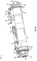
FIG. 1A is a schematic view of an air separation module in accordance with an exemplary embodiment of the invention; -
FIG. 1B is an alternate view of the air separation module ofFIG. 1A ; -
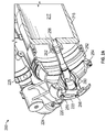
FIG. 2A is a cut-away schematic of an air separation module in accordance with an exemplary embodiment of the invention showing a transfer tube in a first position; -
FIG. 2B is a cut-away schematic of the air separation module ofFIG. 2A showing the transfer tube in a second position; -
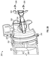
FIG. 3A is a cut-away schematic of an air separation module in accordance with an exemplary embodiment of the invention showing a collar in a first position; -
FIG. 3B is a cut-away schematic of the air separation module ofFIG. 3A showing the collar in a second position; -
FIG. 4 is a schematic view of a removal or installation process in accordance with an exemplary embodiment of the invention; and -
FIG. 5 is a process flow of removing a canister from an air separation module in accordance with an embodiment of the invention. -
FIG. 1A is a schematic view of anair separation module 100 in accordance with an exemplary embodiment of the invention andFIG. 1B shows an alternate view of the sameair separation module 100. Bleed air enters theair separation module 100 atbleed air inlet 102 and passes through an ozone converter/filter 104. The air then passes through first end piping or ducting 106 includingflexible joints 107 and a number of sensors, includingpressure sensor 108 andtemperature sensor 110. The air then passes into afirst end cap 112 that includes afirst transfer tube 114, described below. Thefirst end cap 112 is configured to be in fluid communication with acanister 116 and defines a fluid flow path from thefirst end ducting 106 to thecanister 116. - Thus, after passing through the
end cap 112, the air flows into theair separation canister 116 which defines an interior chamber, shown inFIGS. 2A and2B , that is configured to separate the air into component parts. For example, the air is separated into two fractions, a first fraction that is oxygen rich will exit theair separation module 100 at anoverboard oxygen outlet 118 and a second fraction that is nitrogen rich passes out of theair separation module 100 at asecond end cap 120 that defines a fluid flow path from thefirst canister 116 to second end piping or ducting 124. - The
second end cap 120 includes asecond transfer tube 122 and is substantially similar tofirst end cap 112 andfirst transfer tube 114. The nitrogen rich fraction will then flow through second end ducting 124 andflexible joints 125 and pass a number of sensors including anoxygen sensor 126, atemperature sensor 128, and aflow sensor 130. Aflow control valve 132 is provided in the flow line prior to a check valve 134, which, in combination control, the flow of the separated nitrogen exiting theair separation module 100 atnitrogen outlet 136. Theducting filter 104,flexible joints inlet 102,sensors valves 132, 134, andoutlet 136 may be referred to as ducting elements or filter, valve, and duct assemblies. In general terms, the ducting elements are configured to supply and control the flow of bleed air to theair separation module 100, and configured to supply and control the flow of nitrogen rich air from thecanister 116 to fuel tanks of an aircraft. - The
air separation module 100 is configured to be mounted within an aircraft, and removably connect to various components of the aircraft, such as a flow line that will provide the nitrogen rich fraction to the fuel tanks to provide an inert gas thereto. Theair separation module 100 is configured to be mounted to one or more brackets or other types of connectors or frames that are part of the aircraft. Accordingly, various fittings are provided on the components ofair separation module 100 to enable mounting within an aircraft. For example, as shown inFIGS. 1A and1B ,air separation module 100 includes fittings or retainingmembers canister 116. Although shown herein with three sets of retainingmembers FIGS. 1A and1B , each retainingmember - Canister 116 is releasably retained between the
first end cap 112 and thesecond end cap 120.First end cap 112 is mounted to a part of the aircraft by firststructural attachment points 144, such as vibration isolators or other types of attachment means, andsecond end cap 120 is mounted to another part of the aircraft by secondstructural attachment points 146, such as vibration isolators. Thus, thefirst end cap 112, thesecond end cap 120, and thecanister 116 retained therebetween form and/or add a structural component to theair separation module 100. At afirst end 148,canister 116 removably engages or fits within or to a portion of thefirst end cap 112. At asecond end 150,canister 116 removably engages or fits within or to a portion of thesecond end cap 120. As shown inFIG. 1B ,canister 116 includes acollar 152 at thesecond end 150 which is configured to releasably engage with thesecond end cap 120. When installed, thefirst end 148 and thesecond end 150 of thecanister 116 are releasably retained to thefirst end cap 112 and thesecond end cap 120, respectively, by use of lockingmechanisms 154, such as V-band couplings, although other types of locking mechanisms, coupling devices, retaining devices, etc. may be used without departing from the scope of the invention. Further, although shown with two structural attachment points forming the first and second structural attachment points 144 and 146, those of skill in the art will appreciate that the number of structural attachment points may be varied without departing from the scope of the invention, and that the structural attachment points may be formed as vibration isolators or other types of attachment means, which may be rigid or permit movement of the end caps and canister. - Those of skill in the art will appreciate that variations of the configuration shown in
FIGS. 1A and1B may be possible without departing from the scope of the invention. Thus, these figures and explanations are presented merely for exemplary purposes and the invention is not limited thereby. - In
FIGS. 2A and2B , detailed cut-away views of an end cap, canister, and related features of anair separation module 200 in accordance with an exemplary embodiment of the invention are shown. Features inFIGS. 2A and2B may be substantially similar to features of theair separation module 100 ofFIGS. 1A and1B , and thus like features have the same reference numeral except preceded with a "2" rather than a "1."FIGS. 2A and2B show anend cap 220 removably connected to acanister 216 defining aninterior chamber 217 by means of acollar 252 and alocking mechanism 254.FIGS. 2A and2B further show the operation/configuration of atransfer tube 222 therein. - The
transfer tube 222 is located and movably retained within theend cap 220. The transfer tube, when installed (FIG. 2A ) is configured to convey air from ducting 224, which connects radially to endcap 220. The air flow then is routed approximately ninety degrees to flow axially into thechamber 217 ofcanister 216. The opposite flow is also possible, depending on the flow direction of the air. - The
transfer tube 222 is releasably retained to endcap 220 byfasteners 256, which when engaged with theend cap 220 fixedly secure thetransfer tube 222 into theend cap 220.FIG. 2A showstransfer tube 222 in a first position, andFIG. 2B showstransfer tube 222 in a second position. The first position may be an engaged position wheretransfer tube 222 completes the flow path ofair separation module 200 by enabling a fluid to flow fromcanister 216, through thetransfer tube 222, and into the ducting 224 (including joints 225). Those of skill in the art will appreciate that the opposite or reverse flow is possible depending on the fluid flow direction through theair separation module 200 and which end of thecanister 216 thetransfer tube 222 is installed. - The second position may be a disengaged position where the
transfer tube 222 does not complete the above flow path. In some embodiments, in the second position thetransfer tube 222 may be completely removed from theend cap 220. In such embodiments, for example, thetransfer tube 222 may be retained with relatively short screws, bolts, or other types offasteners 256. - In other embodiments, the
transfer tube 222 may be movably retained to theend cap 220 but not removable therefrom. For example, thetransfer tube 222 may be configured to be withdrawn axially a certain or predetermined distance such that it is not removed from theend cap 220. In such embodiments, thetransfer tube 222 may be secured to theend cap 220 by one ormore fasteners 256 that may be relatively long. To effect the axial disengagement of thetransfer tube 222 from theend cap 220, eachfastener 256 may be turned several rotations to back out a predetermined distance, and thetransfer tube 222 may then be moveable the predetermined distance off of a surface of theend cap 220. - In other embodiments, to accommodate the
fasteners 256, thetransfer tube 222 may be configured with through-holes, withfasteners 256 that may be relatively short, although relatively long fasteners could be used without departing from the scope of the invention. In some such embodiments, the through-holes may be configured as a key-hole slot. The key-hole slot may be configured as an annular slot with an arc length that is at least twice the diameter of a head of thefastener 256. The width of the key-hole slot may be configured such that it is less than the diameter of the head of thefastener 256 at one end and at the other end of the arc length the slot width is larger than a diameter of the head of thefastener 256. In some embodiments, thetransfer tube 222 may be configured as being largely axi-symmetric with no keying features and can be movably rotated when thefasteners 256 are loosened. When rotated and thefasteners 256 are concentric with the enlarged end of the slot of the key-hole, thetransfer tube 222 can be disengaged from thecanister 220 with no further removal of thefasteners 256 required. Upon reinserting thetransfer tube 222 into the fully engaged position, thetransfer tube 222 can be rotated back so that the heads of thefasteners 256 can be seated with maximum contact against the surface of thetransfer tube 222. Further, in some embodiments, because thefasteners 256 may not require complete removal in order to disengage thetransfer tube 222, thefasteners 256 may be fitted with retaining rings or similar features to preclude inadvertent removal. - When in the first, engaged position, the
transfer tube 222 provides sealing engagement with both theend cap 220 and aport 258 ofcanister 216.Seals 260 provide sealing engagement between thetransfer tube 222 and theend cap 220 and may be configured as O-rings or other types of seals known in the art. Further,seal 262 provides sealing engagement between thetransfer tube 222 and theport 258 ofcanister 216. - As shown in
FIGS. 2A and2B ,transfer tube 222 includesapertures 264 that enable a fluid flow through theducting 224, throughend cap 220, throughtransfer tube 222, throughport 258, and into thecanister 216. A similar configuration is provided at each end of the canister, such as that shown inFIGS. 1A and1B , and thus the fluid flow path will be enabled to flow in the opposite direction at the opposite end of theair separation module 200. - Further, as shown in
FIGS. 2A and2B , thecollar 252 is engaged with theend cap 220 and fixedly retained thereto with thelocking mechanism 254. InFIGS. 3A and 3B , the operation of the collar in accordance with embodiments of the invention is shown. Features inFIGS. 3A and 3B may be substantially similar to features of theair separation modules FIGS. 1A, 1B and 2A, 2B , respectively, and thus like features will have the same reference numeral except preceded with a "3" rather than a "1" or a "2." -
Air separation module 300 shows anend cap 320 engaged with acanister 316. InFIGS. 3A and 3B the transfer tube has been removed and is not shown. Although this is done for clarity and explanatory purposes, those of skill in the art will appreciate that transfer tube is not required to be fully removed from the end cap, such as with some of the embodiments described above. - In
FIG. 3A , thecanister 316 is in a first position and inFIG. 3B thecanister 316 is in a second position. The first position may be an installed or engaged position and the second position may be a retracted or disengaged position. As shown, thecollar 352 is configured as a slip joint that moves relative to thecanister 316. In the first position (FIG. 3A ), acollar joining surface 366 of thecollar 352 engages with an endcap joining surface 368 to provide sealing engagement therebetween. Further, apilot surface 370 ofend cap 320 is configured to align and physically support thecanister 316 in the engagement between theend cap 320 and thecanister 316 providing, in part, the structural feature of the module systems disclosed herein. One or more sealing surfaces 372 are provided between thecollar 352 and thecanister 316. The one or more sealing surfaces 372 may be configured to accommodate one or more O-rings or similar sealing devices, which are not shown for clarity purposes, but will be readily appreciated by those of skill in the art. Those of skill in the art will appreciate that other forms or engagement, retention, sealing, and support may be provided without departing from the scope of the invention. For example, thepilot surface 372 may be configured as a plurality of pegs, pins, etc., or may be configured as a flange or similar structure, further, a pilot surface may be provided on the canister instead of or in addition to the end cap. - As noted, the
collar 352 is moveable with respect to thecanister 316. When thecollar 352 is in the second position (FIG. 3B ), thecanister 316 may be removed from or moved relative to theend cap 320, as will be discussed with respect to the embodiment shown inFIG. 4 and process ofFIG. 5 . Then, when thecollar 352 is moved to the first position (FIG. 3A ), thesurface 366 engages with thesurface 368 and a locking mechanism (seeFIGS. 2A and2B ) can be engaged around the two surfaces to lock thecanister 316 in place with respect to theend cap 320. The transfer tube, as discussed above, can then be inserted into theend cap 320 and fixedly attached thereto. Theair separation module 300 is then ready to be used. Further, the reverse process may be carried out to remove thecanister 316. For example, (i) the transfer tube may be removed, (ii) the locking mechanism released, and (iii) thecollar 352 moved to the second position to enable easy release and removal of thecanister 316 from theair separation module 300. - In some embodiments, the
collar 352 may be freely moveable between the first and second positions. In other embodiments, thecollar 352 may be biased toward one of the first position and the second position. Thus, in some embodiments thecollar 352 may be configured with a spring or other similar biasing mechanism that will urge the collar toward the first position or toward the second position, as would be known in the art. - In
FIG. 4 , a schematic showing the removal process of thecanister 416 from theair separation module 400 is shown. The process ofFIG. 4 (and the prior figures) will also be explained with reference toFIG. 5 , which is an exemplary process of removing a canister from an air separation module in accordance with embodiments of the invention. Features inFIG. 4 may be substantially similar to features of the air separation modules discussed above and thus like features will have the same reference numerals except preceded with a "4" rather than a "1," "2," or "3." - In
FIG. 4 , the transfer tube is omitted for clarity, but it may be partly disengaged or completely removed, as described above. Referring toFIG. 2A , thetransfer tube 222, when installed, may prevent thecanister 216 from moving radially relative to theend cap 220. Thus, inFIG. 4 , the removal or disengagement of the transfer tube has been removed, which enables the removal of thecanister 416 from theair separation module 400. Thus, afirst step 502 inprocess 500 entails disengaging and/or removing the transfer tube from theend cap 420 ofmodule 400. Next, atstep 504 the locking mechanism (also not shown inFIG. 4 , as it has been removed) is removed from the engagement between theend cap 420 and thecanister 416. Then, atstep 506, thecollar 452 is slid from the first, engaged position (FIG. 3A ) to the second, disengaged position (FIG. 3B ). Atstep 508, the canister may then be moved from an engaged position, shown as Position A ofFIG. 4 , to a release position, shown as Position B ofFIG. 4 . In the release position B, afirst end 448 may stay engaged or at least partially held or retained by afirst end cap 412. However, in the release position B, thesecond end 450 of thecanister 416 is released from and not engaged with thesecond end cap 420. After the release position B is obtained, thecanister 416 can then be removed from thefirst end cap 412 and be moved to a removed position C atstep 510, shown inFIG. 4 . Thus thecanister 416 may be fully removed from theair separation module 400 while the other components may remain attached to the aircraft. - Those of skill in the art will appreciate that to install a canister within an air separation module as disclosed herein, the reverse process of
FIGS. 4 and5 may be performed. Thus, (i) a canister may be engaged at a first end (in the release position B), (ii) a second end moved upward into the engaged position A, (iii) a collar slid from the disengaged position to the engaged position, (iv) a locking mechanism may be installed, and (v) the transfer tube may be installed and fastened to the end cap. - Those of skill in the art will also appreciate that the order of steps may be varied without departing from the scope of the invention. For example, although described above with the collar being moved prior to installing the transfer tube, these steps may be completed in any order.
- Advantageously, in accordance with various embodiments of the invention, an elegant engagement mechanism for an air separation module is provided. Advantageously, because the canister can be removed by itself, there is no requirement to remove an entire frame or other components from the aircraft during installation and/or replacement of canisters. Further, because the canister is removable, there is no requirement for additional, heavy frames to be installed into and removed from an aircraft in order to provide air separation process. Moreover, the air separation modules disclosed herein, and the processes for employing such modules, enables a very simple process that eliminates difficulties associated with installing and removing air separation module canisters. Additionally, because canister removal described herein may be done on a canister-by-canister basis, if multiple canisters are installed in an aircraft, there is no need to remove an entire frame (and multiple canisters) when replacing or removing only one of the canisters.
- Additionally, advantageously, the installation and/or removal process enabled and described herein may be performed in a relatively short time period, thus providing additional benefits to the disclosed invention.
- While the invention has been described in detail in connection with only a limited number of embodiments, it should be readily understood that the invention is not limited to such disclosed embodiments. Rather, the invention can be modified to incorporate any number of variations, alterations, substitutions or equivalent arrangements not heretofore described, but which are commensurate with the spirit and scope of the invention. Additionally, while various embodiments of the invention have been described, it is to be understood that aspects of the invention may include only some of the described embodiments and/or features.
- For example, although described herein with respect to a single canister installed within an aircraft, the disclosed features may be applied to a multi-canister system. In such systems the mounting elements, rather than being integrated into the flow line features, may be provided and installed at each corner of a multi-canister pack assembly.
- Further, although described and shown herein with the locking mechanism configured as a V-band coupling, those of skill in the art will appreciate that other types of locking mechanisms, couplings, connectors, and engaging mechanisms may be employed without departing from the scope of the invention.
- Accordingly, the invention is not to be seen as limited by the foregoing description, but is only limited by the scope of the appended claims.
Claims (15)
- An air separation module comprising:a canister (116) defining an interior chamber (217) and having a first port at a first end (148) and a second port at a second end (150), the canister (116) configured to permit fluid to pass from the first port to the second port through the interior chamber (217);a first end cap (112) located proximal to the first end (148) of the canister (116) and configured to releasably retain the first end (148) of the canister (116), the first end cap (112) defining a fluid path therethrough;a second end cap (120) located proximal to the second end (150) of the canister (116) and configured to releasably retain the second end (150) of the canister (116), the second end cap (120) defining a fluid path therethrough; anda collar (152) movably configured on the second end (150) of the canister (116) and configured to move from a first position to a second position, wherein the first position defines an engagement between the collar (152) and the second end cap (120), and the second position defines a disengagement between the collar (152) and the second end cap (120) such that the canister (116) may be removed from retention between the first and second end caps (112, 120).
- The air separation module of claim 1, further comprising a transfer tube (114) extending through and removably attached to the first end cap (112), the transfer tube (114) configured to connect the fluid path of the first end cap (112) to the interior chamber (217) of the canister (116).
- The air separation module of any of claims 1-2, further comprising a transfer tube (122) extending through and removably attached to the second end cap (120), the transfer tube (122) configured to connect the fluid path of the second end cap (120) to the interior chamber (217) of the canister (116).
- The air separation module of any of claims 1-3, further comprising a locking mechanism (154) configured to lock the collar (152) to the first end cap (112) in the first position.
- The air separation module of any of claims 1-4, wherein the first end cap (112) and the second end cap (120) each include one or more structural attachment points (144, 146).
- The air separation module of claim 5, wherein the one or more structural attachment points (144, 146) comprise one or more vibration isolators.
- The air separation module of any of claims 1-6, further comprising one or more ducting elements configured to connect at least one of the first and second end caps (112, 120) to an air source.
- The air separation module of claim 7, wherein at least one of the one or more ducting elements are configured to removably attach to a structure of an aircraft.
- A method of removing and installing an air separation module canister in an air separation module, the method comprising:engaging a first end (148) of a canister (116) to a first end cap (112);engaging a second end (150) of the canister (116) to a second end cap (120), the second end (150) of the canister (116) including a collar (152) defining a first position and a second position;moving the collar (152) on the second end (150) of the canister (116) from the second position to the first position to engage the collar (152) with the second end cap (120); andlocking the canister (116) in an engaged position with a locking mechanism (154) between the first end cap (112) and the second end cap (120).
- The method of claim 9 further comprising:after engaging the first end (148) of the canister (116) to the first end cap (112), installing a first transfer tube (114) through the first end cap (112) to fluidly connect the first end cap (112) to the canister (116).
- The method of any of claims 9-10, further comprising:after engaging the second end (150) of the canister (116) to the second end cap (120), installing a second transfer tube (122) through the second end cap (120) to fluidly connect the second end cap (120) to the canister (116).
- The method of any of claims 9-11, further comprising:unlocking the locking mechanism (154);moving the collar (152) from the first position to the second position;disengaging the second end (150) of the canister (116) from the second end cap (120); anddisengaging the first end (148) of the canister (116) from the first end cap (112), thereby removing the canister (116) from engagement between the first and second end caps (112, 120).
- The method of claim 12, further comprising:prior to disengaging the first end (148) of the canister (116) from the first end cap (112), removing a transfer tube (114) configured to fluidly connect the first end cap (112) to the canister (116) from the first end cap (112).
- The method of claim 12 or 13, further comprising:prior to disengaging the second end (50) of the canister (116) from the second end cap (120), removing a transfer tube (120) configured to fluidly connect the second end cap (120) to the canister (116) from the second end cap (120).
- The method of any of claims 9-14, wherein the air separation module includes ducting elements, the method further comprising:releasably mounting the ducting elements to a structure of an aircraft.
Applications Claiming Priority (1)
| Application Number | Priority Date | Filing Date | Title |
|---|---|---|---|
| US14/587,265 US9855544B2 (en) | 2014-12-31 | 2014-12-31 | Canister system for air separation module |
Publications (2)
| Publication Number | Publication Date |
|---|---|
| EP3040278A1 true EP3040278A1 (en) | 2016-07-06 |
| EP3040278B1 EP3040278B1 (en) | 2020-09-23 |
Family
ID=55027618
Family Applications (1)
| Application Number | Title | Priority Date | Filing Date |
|---|---|---|---|
| EP15203240.5A Active EP3040278B1 (en) | 2014-12-31 | 2015-12-31 | Canister system for air separation module |
Country Status (2)
| Country | Link |
|---|---|
| US (1) | US9855544B2 (en) |
| EP (1) | EP3040278B1 (en) |
Cited By (5)
| Publication number | Priority date | Publication date | Assignee | Title |
|---|---|---|---|---|
| EP3835216A1 (en) * | 2019-12-11 | 2021-06-16 | Hamilton Sundstrand Corporation | Air separation modules, nitrogen generation systems, and methods of making air separation modules |
| EP3835215A1 (en) * | 2019-12-11 | 2021-06-16 | Hamilton Sundstrand Corporation | Air separation modules, nitrogen generation systems, and methods of making air separation modules |
| US11491442B2 (en) | 2019-12-11 | 2022-11-08 | Hamilton Sundstrand Corporation | Air separation modules and methods of removing condensate from air separation modules |
| US11571646B2 (en) | 2019-12-11 | 2023-02-07 | Hamilton Sundstrand Corporation | Air separation modules, nitrogen generation systems, and methods of making air separation modules |
| US11772035B2 (en) | 2019-12-11 | 2023-10-03 | Hamilton Sundstrand Corporation | Air separation modules, nitrogen generation systems, and methods of making air separation modules |
Families Citing this family (3)
| Publication number | Priority date | Publication date | Assignee | Title |
|---|---|---|---|---|
| GB201709898D0 (en) * | 2017-06-21 | 2017-08-02 | Airbus Operations Ltd | Fuel tank inerting system |
| US11420151B2 (en) | 2019-02-12 | 2022-08-23 | Hamilton Sundstrand Corporation | Air separation modules, nitrogen generation systems, and methods of making air separation modules |
| US11344841B2 (en) | 2020-03-09 | 2022-05-31 | Hamilton Sundstrand Corporation | Air separation modules and methods of making air separation modules |
Citations (5)
| Publication number | Priority date | Publication date | Assignee | Title |
|---|---|---|---|---|
| US4488889A (en) * | 1983-03-07 | 1984-12-18 | Mccarroll Glenn G | Air cleaner tank |
| US4838901A (en) * | 1988-05-17 | 1989-06-13 | Life Systems, Inc. | Lightweight filter |
| WO2000067885A1 (en) * | 1999-05-05 | 2000-11-16 | Alberta Research Council Inc. | Hollow-fiber membrane devices and methods of assembly |
| US20040065778A1 (en) * | 2002-10-04 | 2004-04-08 | Jones Philip E. | Increasing the performance of aircraft on-board inert gas generating systems by turbocharging |
| US20100024649A1 (en) * | 2005-10-18 | 2010-02-04 | Parker-Hannifin Corporation | Air separation module with load carrying center tube |
Family Cites Families (1)
| Publication number | Priority date | Publication date | Assignee | Title |
|---|---|---|---|---|
| US5013331A (en) * | 1989-06-30 | 1991-05-07 | E. I. Du Pont De Nemours And Company | Permeator with selectable flow rates |
-
2014
- 2014-12-31 US US14/587,265 patent/US9855544B2/en active Active
-
2015
- 2015-12-31 EP EP15203240.5A patent/EP3040278B1/en active Active
Patent Citations (5)
| Publication number | Priority date | Publication date | Assignee | Title |
|---|---|---|---|---|
| US4488889A (en) * | 1983-03-07 | 1984-12-18 | Mccarroll Glenn G | Air cleaner tank |
| US4838901A (en) * | 1988-05-17 | 1989-06-13 | Life Systems, Inc. | Lightweight filter |
| WO2000067885A1 (en) * | 1999-05-05 | 2000-11-16 | Alberta Research Council Inc. | Hollow-fiber membrane devices and methods of assembly |
| US20040065778A1 (en) * | 2002-10-04 | 2004-04-08 | Jones Philip E. | Increasing the performance of aircraft on-board inert gas generating systems by turbocharging |
| US20100024649A1 (en) * | 2005-10-18 | 2010-02-04 | Parker-Hannifin Corporation | Air separation module with load carrying center tube |
Cited By (6)
| Publication number | Priority date | Publication date | Assignee | Title |
|---|---|---|---|---|
| EP3835216A1 (en) * | 2019-12-11 | 2021-06-16 | Hamilton Sundstrand Corporation | Air separation modules, nitrogen generation systems, and methods of making air separation modules |
| EP3835215A1 (en) * | 2019-12-11 | 2021-06-16 | Hamilton Sundstrand Corporation | Air separation modules, nitrogen generation systems, and methods of making air separation modules |
| US11491442B2 (en) | 2019-12-11 | 2022-11-08 | Hamilton Sundstrand Corporation | Air separation modules and methods of removing condensate from air separation modules |
| US11571646B2 (en) | 2019-12-11 | 2023-02-07 | Hamilton Sundstrand Corporation | Air separation modules, nitrogen generation systems, and methods of making air separation modules |
| US11772035B2 (en) | 2019-12-11 | 2023-10-03 | Hamilton Sundstrand Corporation | Air separation modules, nitrogen generation systems, and methods of making air separation modules |
| US11931684B2 (en) | 2019-12-11 | 2024-03-19 | Hamilton Sundstrand Corporation | Air separation modules, nitrogen generation systems, and methods of making air separation modules |
Also Published As
| Publication number | Publication date |
|---|---|
| EP3040278B1 (en) | 2020-09-23 |
| US9855544B2 (en) | 2018-01-02 |
| US20160184793A1 (en) | 2016-06-30 |
Similar Documents
| Publication | Publication Date | Title |
|---|---|---|
| US9855544B2 (en) | Canister system for air separation module | |
| US9452381B2 (en) | Modular canister modules for air separation systems | |
| KR102093521B1 (en) | Quick connector | |
| US20140360373A1 (en) | Air separation module with removable core | |
| US9745926B2 (en) | Fluid line coupling | |
| US9181848B2 (en) | Turbocharger exhaust manifold system | |
| US20150292524A1 (en) | Jet pump | |
| CN106166534A (en) | Bodies of fluid and the distributing equipment of actuator body and method is fixed with quick connecting elements | |
| TWI711914B (en) | Accessory attachment apparatus and temperature-controlled fluid forcing system | |
| BR112013026322A2 (en) | compressed air coupling | |
| CN110654523A (en) | Pipeline stringer | |
| US20100024649A1 (en) | Air separation module with load carrying center tube | |
| EP2872813A2 (en) | Claw quick disconnect intercom fitting | |
| CN103383114B (en) | System and method for assembling the end cap of burner | |
| CN107208895B (en) | Fuel supply system with quick snap-fit fuel feed joint for gas turbine combustor | |
| US12024309B2 (en) | Fuel tank diffuser | |
| CN111527042A (en) | Coupling for transporting fluids, method for closing fluid passages of the coupling and preferred uses of the coupling | |
| CN105556003B (en) | Heating modules for use in thermal hydrolysis reactors | |
| CN203517108U (en) | Female joint | |
| US20170120166A1 (en) | Filter device, in particular liquid filter | |
| KR101670725B1 (en) | Tube pipe connector having one-touch type fitting structure | |
| US20160199867A1 (en) | Changing device for coating media and coating system for coating objects | |
| EP2952791A1 (en) | Shut-off valve | |
| US10857397B2 (en) | Bayonet hose connector assembly mechanism in powered air purifying air respirator housing | |
| EP3546371B1 (en) | Installation tool and method |
Legal Events
| Date | Code | Title | Description |
|---|---|---|---|
| PUAI | Public reference made under article 153(3) epc to a published international application that has entered the european phase |
Free format text: ORIGINAL CODE: 0009012 |
|
| AK | Designated contracting states |
Kind code of ref document: A1 Designated state(s): AL AT BE BG CH CY CZ DE DK EE ES FI FR GB GR HR HU IE IS IT LI LT LU LV MC MK MT NL NO PL PT RO RS SE SI SK SM TR |
|
| AX | Request for extension of the european patent |
Extension state: BA ME |
|
| STAA | Information on the status of an ep patent application or granted ep patent |
Free format text: STATUS: REQUEST FOR EXAMINATION WAS MADE |
|
| 17P | Request for examination filed |
Effective date: 20170105 |
|
| RBV | Designated contracting states (corrected) |
Designated state(s): AL AT BE BG CH CY CZ DE DK EE ES FI FR GB GR HR HU IE IS IT LI LT LU LV MC MK MT NL NO PL PT RO RS SE SI SK SM TR |
|
| STAA | Information on the status of an ep patent application or granted ep patent |
Free format text: STATUS: EXAMINATION IS IN PROGRESS |
|
| 17Q | First examination report despatched |
Effective date: 20181109 |
|
| GRAP | Despatch of communication of intention to grant a patent |
Free format text: ORIGINAL CODE: EPIDOSNIGR1 |
|
| STAA | Information on the status of an ep patent application or granted ep patent |
Free format text: STATUS: GRANT OF PATENT IS INTENDED |
|
| INTG | Intention to grant announced |
Effective date: 20200422 |
|
| GRAS | Grant fee paid |
Free format text: ORIGINAL CODE: EPIDOSNIGR3 |
|
| GRAA | (expected) grant |
Free format text: ORIGINAL CODE: 0009210 |
|
| STAA | Information on the status of an ep patent application or granted ep patent |
Free format text: STATUS: THE PATENT HAS BEEN GRANTED |
|
| AK | Designated contracting states |
Kind code of ref document: B1 Designated state(s): AL AT BE BG CH CY CZ DE DK EE ES FI FR GB GR HR HU IE IS IT LI LT LU LV MC MK MT NL NO PL PT RO RS SE SI SK SM TR |
|
| RAP1 | Party data changed (applicant data changed or rights of an application transferred) |
Owner name: HAMILTON SUNDSTRAND CORPORATION |
|
| REG | Reference to a national code |
Ref country code: GB Ref legal event code: FG4D |
|
| REG | Reference to a national code |
Ref country code: CH Ref legal event code: EP |
|
| REG | Reference to a national code |
Ref country code: IE Ref legal event code: FG4D |
|
| REG | Reference to a national code |
Ref country code: AT Ref legal event code: REF Ref document number: 1316159 Country of ref document: AT Kind code of ref document: T Effective date: 20201015 Ref country code: DE Ref legal event code: R096 Ref document number: 602015059449 Country of ref document: DE |
|
| PG25 | Lapsed in a contracting state [announced via postgrant information from national office to epo] |
Ref country code: GR Free format text: LAPSE BECAUSE OF FAILURE TO SUBMIT A TRANSLATION OF THE DESCRIPTION OR TO PAY THE FEE WITHIN THE PRESCRIBED TIME-LIMIT Effective date: 20201224 Ref country code: NO Free format text: LAPSE BECAUSE OF FAILURE TO SUBMIT A TRANSLATION OF THE DESCRIPTION OR TO PAY THE FEE WITHIN THE PRESCRIBED TIME-LIMIT Effective date: 20201223 Ref country code: FI Free format text: LAPSE BECAUSE OF FAILURE TO SUBMIT A TRANSLATION OF THE DESCRIPTION OR TO PAY THE FEE WITHIN THE PRESCRIBED TIME-LIMIT Effective date: 20200923 Ref country code: HR Free format text: LAPSE BECAUSE OF FAILURE TO SUBMIT A TRANSLATION OF THE DESCRIPTION OR TO PAY THE FEE WITHIN THE PRESCRIBED TIME-LIMIT Effective date: 20200923 Ref country code: SE Free format text: LAPSE BECAUSE OF FAILURE TO SUBMIT A TRANSLATION OF THE DESCRIPTION OR TO PAY THE FEE WITHIN THE PRESCRIBED TIME-LIMIT Effective date: 20200923 Ref country code: BG Free format text: LAPSE BECAUSE OF FAILURE TO SUBMIT A TRANSLATION OF THE DESCRIPTION OR TO PAY THE FEE WITHIN THE PRESCRIBED TIME-LIMIT Effective date: 20201223 |
|
| REG | Reference to a national code |
Ref country code: AT Ref legal event code: MK05 Ref document number: 1316159 Country of ref document: AT Kind code of ref document: T Effective date: 20200923 |
|
| PG25 | Lapsed in a contracting state [announced via postgrant information from national office to epo] |
Ref country code: RS Free format text: LAPSE BECAUSE OF FAILURE TO SUBMIT A TRANSLATION OF THE DESCRIPTION OR TO PAY THE FEE WITHIN THE PRESCRIBED TIME-LIMIT Effective date: 20200923 Ref country code: LV Free format text: LAPSE BECAUSE OF FAILURE TO SUBMIT A TRANSLATION OF THE DESCRIPTION OR TO PAY THE FEE WITHIN THE PRESCRIBED TIME-LIMIT Effective date: 20200923 |
|
| REG | Reference to a national code |
Ref country code: NL Ref legal event code: MP Effective date: 20200923 |
|
| REG | Reference to a national code |
Ref country code: LT Ref legal event code: MG4D |
|
| PG25 | Lapsed in a contracting state [announced via postgrant information from national office to epo] |
Ref country code: SM Free format text: LAPSE BECAUSE OF FAILURE TO SUBMIT A TRANSLATION OF THE DESCRIPTION OR TO PAY THE FEE WITHIN THE PRESCRIBED TIME-LIMIT Effective date: 20200923 Ref country code: RO Free format text: LAPSE BECAUSE OF FAILURE TO SUBMIT A TRANSLATION OF THE DESCRIPTION OR TO PAY THE FEE WITHIN THE PRESCRIBED TIME-LIMIT Effective date: 20200923 Ref country code: EE Free format text: LAPSE BECAUSE OF FAILURE TO SUBMIT A TRANSLATION OF THE DESCRIPTION OR TO PAY THE FEE WITHIN THE PRESCRIBED TIME-LIMIT Effective date: 20200923 Ref country code: LT Free format text: LAPSE BECAUSE OF FAILURE TO SUBMIT A TRANSLATION OF THE DESCRIPTION OR TO PAY THE FEE WITHIN THE PRESCRIBED TIME-LIMIT Effective date: 20200923 Ref country code: NL Free format text: LAPSE BECAUSE OF FAILURE TO SUBMIT A TRANSLATION OF THE DESCRIPTION OR TO PAY THE FEE WITHIN THE PRESCRIBED TIME-LIMIT Effective date: 20200923 Ref country code: PT Free format text: LAPSE BECAUSE OF FAILURE TO SUBMIT A TRANSLATION OF THE DESCRIPTION OR TO PAY THE FEE WITHIN THE PRESCRIBED TIME-LIMIT Effective date: 20210125 Ref country code: CZ Free format text: LAPSE BECAUSE OF FAILURE TO SUBMIT A TRANSLATION OF THE DESCRIPTION OR TO PAY THE FEE WITHIN THE PRESCRIBED TIME-LIMIT Effective date: 20200923 |
|
| PG25 | Lapsed in a contracting state [announced via postgrant information from national office to epo] |
Ref country code: PL Free format text: LAPSE BECAUSE OF FAILURE TO SUBMIT A TRANSLATION OF THE DESCRIPTION OR TO PAY THE FEE WITHIN THE PRESCRIBED TIME-LIMIT Effective date: 20200923 Ref country code: IS Free format text: LAPSE BECAUSE OF FAILURE TO SUBMIT A TRANSLATION OF THE DESCRIPTION OR TO PAY THE FEE WITHIN THE PRESCRIBED TIME-LIMIT Effective date: 20210123 Ref country code: AT Free format text: LAPSE BECAUSE OF FAILURE TO SUBMIT A TRANSLATION OF THE DESCRIPTION OR TO PAY THE FEE WITHIN THE PRESCRIBED TIME-LIMIT Effective date: 20200923 Ref country code: AL Free format text: LAPSE BECAUSE OF FAILURE TO SUBMIT A TRANSLATION OF THE DESCRIPTION OR TO PAY THE FEE WITHIN THE PRESCRIBED TIME-LIMIT Effective date: 20200923 Ref country code: ES Free format text: LAPSE BECAUSE OF FAILURE TO SUBMIT A TRANSLATION OF THE DESCRIPTION OR TO PAY THE FEE WITHIN THE PRESCRIBED TIME-LIMIT Effective date: 20200923 |
|
| REG | Reference to a national code |
Ref country code: DE Ref legal event code: R097 Ref document number: 602015059449 Country of ref document: DE |
|
| PG25 | Lapsed in a contracting state [announced via postgrant information from national office to epo] |
Ref country code: SK Free format text: LAPSE BECAUSE OF FAILURE TO SUBMIT A TRANSLATION OF THE DESCRIPTION OR TO PAY THE FEE WITHIN THE PRESCRIBED TIME-LIMIT Effective date: 20200923 |
|
| REG | Reference to a national code |
Ref country code: DE Ref legal event code: R119 Ref document number: 602015059449 Country of ref document: DE |
|
| PLBE | No opposition filed within time limit |
Free format text: ORIGINAL CODE: 0009261 |
|
| REG | Reference to a national code |
Ref country code: CH Ref legal event code: PL |
|
| STAA | Information on the status of an ep patent application or granted ep patent |
Free format text: STATUS: NO OPPOSITION FILED WITHIN TIME LIMIT |
|
| PG25 | Lapsed in a contracting state [announced via postgrant information from national office to epo] |
Ref country code: DK Free format text: LAPSE BECAUSE OF FAILURE TO SUBMIT A TRANSLATION OF THE DESCRIPTION OR TO PAY THE FEE WITHIN THE PRESCRIBED TIME-LIMIT Effective date: 20200923 Ref country code: MC Free format text: LAPSE BECAUSE OF FAILURE TO SUBMIT A TRANSLATION OF THE DESCRIPTION OR TO PAY THE FEE WITHIN THE PRESCRIBED TIME-LIMIT Effective date: 20200923 Ref country code: SI Free format text: LAPSE BECAUSE OF FAILURE TO SUBMIT A TRANSLATION OF THE DESCRIPTION OR TO PAY THE FEE WITHIN THE PRESCRIBED TIME-LIMIT Effective date: 20200923 |
|
| 26N | No opposition filed |
Effective date: 20210624 |
|
| REG | Reference to a national code |
Ref country code: BE Ref legal event code: MM Effective date: 20201231 |
|
| PG25 | Lapsed in a contracting state [announced via postgrant information from national office to epo] |
Ref country code: LU Free format text: LAPSE BECAUSE OF NON-PAYMENT OF DUE FEES Effective date: 20201231 Ref country code: IT Free format text: LAPSE BECAUSE OF FAILURE TO SUBMIT A TRANSLATION OF THE DESCRIPTION OR TO PAY THE FEE WITHIN THE PRESCRIBED TIME-LIMIT Effective date: 20200923 Ref country code: IE Free format text: LAPSE BECAUSE OF NON-PAYMENT OF DUE FEES Effective date: 20201231 |
|
| PG25 | Lapsed in a contracting state [announced via postgrant information from national office to epo] |
Ref country code: DE Free format text: LAPSE BECAUSE OF NON-PAYMENT OF DUE FEES Effective date: 20210701 Ref country code: CH Free format text: LAPSE BECAUSE OF NON-PAYMENT OF DUE FEES Effective date: 20201231 Ref country code: LI Free format text: LAPSE BECAUSE OF NON-PAYMENT OF DUE FEES Effective date: 20201231 |
|
| PG25 | Lapsed in a contracting state [announced via postgrant information from national office to epo] |
Ref country code: TR Free format text: LAPSE BECAUSE OF FAILURE TO SUBMIT A TRANSLATION OF THE DESCRIPTION OR TO PAY THE FEE WITHIN THE PRESCRIBED TIME-LIMIT Effective date: 20200923 Ref country code: MT Free format text: LAPSE BECAUSE OF FAILURE TO SUBMIT A TRANSLATION OF THE DESCRIPTION OR TO PAY THE FEE WITHIN THE PRESCRIBED TIME-LIMIT Effective date: 20200923 Ref country code: CY Free format text: LAPSE BECAUSE OF FAILURE TO SUBMIT A TRANSLATION OF THE DESCRIPTION OR TO PAY THE FEE WITHIN THE PRESCRIBED TIME-LIMIT Effective date: 20200923 |
|
| PG25 | Lapsed in a contracting state [announced via postgrant information from national office to epo] |
Ref country code: MK Free format text: LAPSE BECAUSE OF FAILURE TO SUBMIT A TRANSLATION OF THE DESCRIPTION OR TO PAY THE FEE WITHIN THE PRESCRIBED TIME-LIMIT Effective date: 20200923 |
|
| PG25 | Lapsed in a contracting state [announced via postgrant information from national office to epo] |
Ref country code: BE Free format text: LAPSE BECAUSE OF NON-PAYMENT OF DUE FEES Effective date: 20201231 |
|
| P01 | Opt-out of the competence of the unified patent court (upc) registered |
Effective date: 20230522 |
|
| PGFP | Annual fee paid to national office [announced via postgrant information from national office to epo] |
Ref country code: GB Payment date: 20251119 Year of fee payment: 11 |
|
| PGFP | Annual fee paid to national office [announced via postgrant information from national office to epo] |
Ref country code: FR Payment date: 20251120 Year of fee payment: 11 |