EP3040274A1 - Removable aircraft headrest - Google Patents
Removable aircraft headrest Download PDFInfo
- Publication number
- EP3040274A1 EP3040274A1 EP15203158.9A EP15203158A EP3040274A1 EP 3040274 A1 EP3040274 A1 EP 3040274A1 EP 15203158 A EP15203158 A EP 15203158A EP 3040274 A1 EP3040274 A1 EP 3040274A1
- Authority
- EP
- European Patent Office
- Prior art keywords
- seat
- pawl
- bayonet
- seat frame
- headrest
- Prior art date
- Legal status (The legal status is an assumption and is not a legal conclusion. Google has not performed a legal analysis and makes no representation as to the accuracy of the status listed.)
- Granted
Links
Images


Classifications
-
- B—PERFORMING OPERATIONS; TRANSPORTING
- B64—AIRCRAFT; AVIATION; COSMONAUTICS
- B64D—EQUIPMENT FOR FITTING IN OR TO AIRCRAFT; FLIGHT SUITS; PARACHUTES; ARRANGEMENT OR MOUNTING OF POWER PLANTS OR PROPULSION TRANSMISSIONS IN AIRCRAFT
- B64D11/00—Passenger or crew accommodation; Flight-deck installations not otherwise provided for
- B64D11/06—Arrangements of seats, or adaptations or details specially adapted for aircraft seats
- B64D11/0639—Arrangements of seats, or adaptations or details specially adapted for aircraft seats with features for adjustment or converting of seats
- B64D11/0642—Adjustable headrests
-
- B—PERFORMING OPERATIONS; TRANSPORTING
- B60—VEHICLES IN GENERAL
- B60N—SEATS SPECIALLY ADAPTED FOR VEHICLES; VEHICLE PASSENGER ACCOMMODATION NOT OTHERWISE PROVIDED FOR
- B60N2/00—Seats specially adapted for vehicles; Arrangement or mounting of seats in vehicles
- B60N2/80—Head-rests
- B60N2/882—Head-rests detachable
-
- B—PERFORMING OPERATIONS; TRANSPORTING
- B64—AIRCRAFT; AVIATION; COSMONAUTICS
- B64D—EQUIPMENT FOR FITTING IN OR TO AIRCRAFT; FLIGHT SUITS; PARACHUTES; ARRANGEMENT OR MOUNTING OF POWER PLANTS OR PROPULSION TRANSMISSIONS IN AIRCRAFT
- B64D11/00—Passenger or crew accommodation; Flight-deck installations not otherwise provided for
- B64D11/06—Arrangements of seats, or adaptations or details specially adapted for aircraft seats
- B64D11/0691—Arrangements of seats, or adaptations or details specially adapted for aircraft seats specially adapted for cabin crew
-
- B—PERFORMING OPERATIONS; TRANSPORTING
- B60—VEHICLES IN GENERAL
- B60N—SEATS SPECIALLY ADAPTED FOR VEHICLES; VEHICLE PASSENGER ACCOMMODATION NOT OTHERWISE PROVIDED FOR
- B60N2/00—Seats specially adapted for vehicles; Arrangement or mounting of seats in vehicles
- B60N2/80—Head-rests
-
- B—PERFORMING OPERATIONS; TRANSPORTING
- B60—VEHICLES IN GENERAL
- B60N—SEATS SPECIALLY ADAPTED FOR VEHICLES; VEHICLE PASSENGER ACCOMMODATION NOT OTHERWISE PROVIDED FOR
- B60N2/00—Seats specially adapted for vehicles; Arrangement or mounting of seats in vehicles
- B60N2/80—Head-rests
- B60N2/806—Head-rests movable or adjustable
-
- B—PERFORMING OPERATIONS; TRANSPORTING
- B60—VEHICLES IN GENERAL
- B60N—SEATS SPECIALLY ADAPTED FOR VEHICLES; VEHICLE PASSENGER ACCOMMODATION NOT OTHERWISE PROVIDED FOR
- B60N2/00—Seats specially adapted for vehicles; Arrangement or mounting of seats in vehicles
- B60N2/80—Head-rests
- B60N2/806—Head-rests movable or adjustable
- B60N2/809—Head-rests movable or adjustable vertically slidable
- B60N2/812—Head-rests movable or adjustable vertically slidable characterised by their locking devices
-
- B—PERFORMING OPERATIONS; TRANSPORTING
- B60—VEHICLES IN GENERAL
- B60N—SEATS SPECIALLY ADAPTED FOR VEHICLES; VEHICLE PASSENGER ACCOMMODATION NOT OTHERWISE PROVIDED FOR
- B60N2/00—Seats specially adapted for vehicles; Arrangement or mounting of seats in vehicles
- B60N2/80—Head-rests
- B60N2/888—Head-rests with arrangements for protecting against abnormal g-forces, e.g. by displacement of the head-rest
-
- B—PERFORMING OPERATIONS; TRANSPORTING
- B60—VEHICLES IN GENERAL
- B60N—SEATS SPECIALLY ADAPTED FOR VEHICLES; VEHICLE PASSENGER ACCOMMODATION NOT OTHERWISE PROVIDED FOR
- B60N2/00—Seats specially adapted for vehicles; Arrangement or mounting of seats in vehicles
- B60N2/80—Head-rests
- B60N2/897—Head-rests with sleeves located in the back-rest for guiding the rods of the head-rest
Definitions
- the present disclosure relates generally to aircraft seats. More particularly, the present disclosure relates to removable headrests for aircraft seats.
- Certain aircraft cabin attendant seats are designed to include a locking removable headrest.
- the seats and locking removable headrests may be subjected to rigorous testing, in which the seats must perform adequately under substantial force and warping.
- Prior designs included a pin or latch on each side of the headrest which could be unlocked in order to remove the headrest and manually engaged after reinserting the headrest to lock the headrest in place.
- Exemplary embodiments of the invention include a seat that may comprise a seat frame, a backrest, a headrest, and a locking mechanism.
- the headrest may comprise a bayonet.
- the locking mechanism may be configured to lock the bayonet within the seat frame.
- the locking mechanism may be configured to release in response to a pressure on the backrest.
- Particular embodiments of the invention may include any of the following features, alone or in combination.
- the locking mechanism may comprise a linkage and a pawl.
- the pawl may be coupled to the seat frame.
- the linkage may comprise a cantilevered tab configured to transmit a force from the backrest to the pawl.
- the pawl may be biased by a torsion spring.
- the pawl may comprise a cut-out, in particular a curved cut-out.
- the linkage may comprise a release member located within the cut-out.
- the torsion spring may be configured to cause the pawl to rotate into a ratchet slot in the bayonet in response to the bayonet being inserted within the seat frame.
- the torsion spring may comprise a first end in contact with the seat frame and a second end in contact with a lever on the pawl, wherein the pawl is biased rotationally by the torsion spring.
- the seat may comprise a linkage coupled to the seat frame, the linkage comprising a main body, a release member extending from the main body and located within the curved cut-out in the pawl, and a cantilevered tab perpendicular to the main body.
- the seat may comprise an upper backrest. The upper backrest may be biased in a forward position by the cantilevered tab.
- the seat may comprise a set screw and a tightening pin configured to decrease vibrations between the bayonet and the seat frame.
- the bayonet may be locked within the seat frame by the pawl.
- the pawl may be located within a ratchet slot in the bayonet.
- a travel stop may be coupled to the seat frame. The travel stop may be configured to limit rearward movement of the upper backrest.
- the pawl may be configured to unlock in response to a pressure on the upper backrest.
- the pawl may be configured to automatically lock a bayonet within the seat frame in response to the bayonet being inserted within the seat frame.
- Exemplary embodiments of the invention further include an aircraft seat that may comprise a seat frame, a pawl, a torsion spring, a linkage, and an upper backrest.
- the pawl may be coupled to the seat frame.
- the pawl may comprise a curved cut-out.
- the torsion spring may be coupled to the pawl.
- the torsion spring may comprise a first end in contact with the seat frame and a second end in contact with a lever on the pawl.
- the pawl may be biased rotationally by the torsion spring.
- the linkage may be coupled to the seat frame.
- the linkage may comprise a main body, a release member extending from the main body and located within the curved cut-out in the pawl, and a cantilevered tab perpendicular to the main body.
- the upper backrest may be biased in a forward position by the cantilevered tab.
- Particular embodiments of the invention may include any of the following features, alone or in combination.
- the seat may comprise a bayonet locked within the seat frame by the pawl.
- the pawl may be located within a ratchet slot in the bayonet.
- a travel stop may be coupled to the seat frame. The travel stop may be configured to limit rearward movement of the upper backrest.
- the pawl may be configured to unlock in response to a pressure on the upper backrest.
- the pawl may be configured to automatically lock a bayonet within the seat frame in response to the bayonet being inserted within the seat frame.
- a set screw and a tightening pin may be configured to decrease vibrations between a bayonet and the seat frame.
- the cantilevered tab may be configured to transmit a force from the backrest to the pawl.
- the torsion spring may be configured to cause the pawl to rotate into the ratchet slot in the bayonet in response to the bayonet being inserted within the seat frame.
- the headrest may automatically lock in place in response to being inserted within the seat frame.
- the headrest may be removed by pressing on an upper backrest in the seat.
- the upper backrest may release a locking mechanism, and the headrest may be pulled upward in order to remove the headrest from the seat.
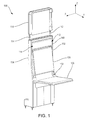
- a seat 100 with a removable headrest 110 is illustrated according to various embodiments.
- X-y-z axes are shown for ease of illustration.
- the term forward represents the positive y-direction
- the term right represents the positive x-direction
- the term left represents the negative x-direction
- the term down represents the negative z-direction
- the term up represents the positive z-direction.
- the seat 100 may be a cabin attendant seat for an aircraft.
- Seat 100 may comprise a seat back 120 and a seat bottom 130.
- Seat bottom 130 may pivot about a hinge 132, such that the seat bottom 130 may be stowed against the seat back 120 when the seat bottom 130 is not in use.
- the seat 100 may comprise a left seat frame 102 and a right seat frame 104.
- the headrest 110 may comprise a left bayonet 112 and a right bayonet 114.
- the left bayonet 112 and the right bayonet 114 may extend downward from the headrest 110.
- the left bayonet 112 may be configured to be inserted into the left seat frame 102
- the right bayonet 114 may be configured to be inserted into the right seat frame 104.
- the seat 100 may comprise a locking mechanism, such that in response to being inserted into the left seat frame 102 and the right seat frame 104, the left bayonet 112 and the right bayonet 114 may be locked in place.
- the locking mechanism may prevent the headrest 110 from being detached from the seat 100.
- the seat 100 may comprise an upper backrest 140.
- the upper backrest 140 may extend between the left seat frame 102 and the right seat frame 104.
- the upper backrest 140 may be located above the seat back 120.
- the upper backrest 140 may be part of a release mechanism to unlock the locking mechanism and remove the headrest 110 from the seat 100.
- the release mechanism In response to pressure on a left side 142 of the upper backrest 140, the release mechanism may unlock the left bayonet 112.
- the release mechanism may unlock the right bayonet 114.
- the headrest 110 may be removed by applying pressure to one side of the upper backrest 140 and partially removing the corresponding bayonet, then applying pressure to the opposite side of the upper backrest 140 and removing the opposite bayonet.
- both the left bayonet 112 and the right bayonet 114 may be unlocked, and the headrest 110 may be removed by pulling upward on the headrest.
- the left bayonet 112 and the right bayonet 114 may lock and unlock independently from each other. Thus, even in the event of failure of one locking mechanism, the headrest 110 may still be locked in place.
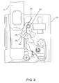
- FIG. 2 a side view of the left bayonet 112 partially inserted into the left seat frame 102 is illustrated according to various embodiments.
- the left bayonet 112 may contact a pawl 250.
- the pawl 250 may be biased in a clockwise direction by a torsion spring 252.
- the torsion spring 252 may comprise a first end 253 coupled to the left seat frame 102, and a second end 255 coupled to a lever 256 on the pawl 250.
- the left bayonet 112 may apply a torque on the pawl 250 in the counter-clockwise direction which is larger than the torque from the torsion spring 252, causing the pawl 250 to rotate in the counter-clockwise direction.
- the left bayonet 112 may slide against the pawl 250 until the left bayonet 112 is fully inserted into the left seat frame 102.
- the left bayonet 112 locked within the left seat frame 102 is illustrated according to various embodiments.
- the left bayonet 112 is fully inserted within the left seat frame 102.
- the left bayonet 112 may comprise a ratchet slot 213.
- the ratchet slot 213 may be recessed from a front face 215 of the left bayonet 112.
- the ratchet slot 213 may be configured to receive the pawl 250.
- the front face 215 of the left bayonet 112 may no longer apply a torque on the pawl 250, and the torsion spring 252 may cause the pawl 250 to rotate clockwise into the ratchet slot 213. Interference between the pawl 250 and the ratchet slot 213 prevents the left bayonet 112 from being removed from the left seat frame 102. Thus, the pawl 250 locks the left bayonet 112 within the left seat frame 102. The torsion spring 252 may prevent the pawl 250 from rotating counter-clockwise out the ratchet slot 213.
- a linkage 460 may be coupled to the left seat frame 102.
- the linkage 460 is configured to transmit a force between the upper backrest 140 and the pawl 250.
- the linkage 460 may comprise a main body 462.
- the main body 462 may be substantially coplanar with the pawl 250.
- a release member 464 may extend from and be coplanar with the main body 462.
- the release member 464 may be located within a cut-out 454 in the pawl 250.
- the cut-out 454 may be curved such that the release member 464 may remain within the cut-out 454 in response to the linkage 460 and pawl 250 rotating relative to one another.
- the linkage 460 may comprise a cantilevered tab 466 extending substantially perpendicular from the main body 462 in a direction away from the left seat frame 102.
- the cantilevered tab 466 may be configured to transmit a force from the upper backrest 140, through the main body 462 and the release member 464 to the pawl 250.
- the upper backrest 140 may be depressed in a rearward direction (negative y-direction) in order to unlock the left bayonet 112.
- the upper backrest 140 may contact the cantilevered tab 466, applying a torque on the linkage 460 in the clockwise direction about a bolt 468.
- the linkage 460 may rotate in the clockwise direction, causing the release member 464 to contact the cut-out 454 and apply a torque on the pawl 250 in a counter-clockwise direction about the pivot joint 257.
- the pawl 250 may rotate in a counter-clockwise direction, and the left bayonet 112 may be pulled upward out of the left seat frame 102.
- the torsion spring 252 may cause the pawl 250 to rotate back in the clockwise direction, in turn causing the linkage 460 to rotate in the counter-clockwise direction, and forcing the upper backrest 140 back to the undepressed position.
- the upper backrest 140 may curve around a post 442.
- the post 442 may be biased in the forward direction by a spring.
- the post may force the upper backrest 140 back to the undepressed position.
- FIG. 5 a perspective view of the left bayonet 112 in the unlocked position is illustrated according to various embodiments.
- the upper backrest 140 may be pressed in the rearward direction.
- a travel stop 570 may be coupled to the left seat frame 102. The upper backrest 140 may contact the travel stop 570, and the travel stop may prevent further rearward movement of the upper backrest 140.
- the seat 100 may comprise a tightening pin 580.
- a set screw 585 may be located adjacent to the tightening pin 580.
- the tightening pin 580 and set screw 585 may be calibrated to decrease the amount of vibration of the left bayonet 112 within the left seat frame 102.
- the left bayonet 112 may be inserted within the left seat frame 102, and the set screw 585 may be tightened, causing the tightening pin 580 to tighten against the left bayonet 112.
- the set screw 585 may be tightened to decrease vibrations between the left bayonet 112 and left seat frame 102, without applying too much load on the left bayonet 112 which would prevent the left bayonet 112 from being removed from the left seat frame 102.
- the manufacturing tolerances may be greater by allowing for the tightening pin 580 and set screw 585 to be adjusted after manufacture of the individual components.
- the left side of the seat 100 has been described in detail, the right side of the seat 100 may comprise an identical or similar locking mechanism. Additionally, although the seat has been described primarily with reference to aircraft applications, the present disclosure may be utilized in any situation in which a locking removable headrest is desirable.
- references to "one embodiment”, “an embodiment”, “various embodiments”, etc. indicate that the embodiment described may include a particular feature, structure, or characteristic, but every embodiment may not necessarily include the particular feature, structure, or characteristic. Moreover, such phrases are not necessarily referring to the same embodiment. Further, when a particular feature, structure, or characteristic is described in connection with an embodiment, it is submitted that it is within the knowledge of one skilled in the art to affect such feature, structure, or characteristic in connection with other embodiments whether or not explicitly described. After reading the description, it will be apparent to one skilled in the relevant art(s) how to implement the disclosure in alternative embodiments.
Landscapes
- Engineering & Computer Science (AREA)
- Aviation & Aerospace Engineering (AREA)
- Transportation (AREA)
- Mechanical Engineering (AREA)
- Seats For Vehicles (AREA)
Abstract
Description
- The present disclosure relates generally to aircraft seats. More particularly, the present disclosure relates to removable headrests for aircraft seats.
- Certain aircraft cabin attendant seats are designed to include a locking removable headrest. The seats and locking removable headrests may be subjected to rigorous testing, in which the seats must perform adequately under substantial force and warping. Prior designs included a pin or latch on each side of the headrest which could be unlocked in order to remove the headrest and manually engaged after reinserting the headrest to lock the headrest in place.
- Exemplary embodiments of the invention include a seat that may comprise a seat frame, a backrest, a headrest, and a locking mechanism. The headrest may comprise a bayonet. The locking mechanism may be configured to lock the bayonet within the seat frame. The locking mechanism may be configured to release in response to a pressure on the backrest.
- Particular embodiments of the invention may include any of the following features, alone or in combination.
- The locking mechanism may comprise a linkage and a pawl. The pawl may be coupled to the seat frame. The linkage may comprise a cantilevered tab configured to transmit a force from the backrest to the pawl. The pawl may be biased by a torsion spring. The pawl may comprise a cut-out, in particular a curved cut-out. The linkage may comprise a release member located within the cut-out. The torsion spring may be configured to cause the pawl to rotate into a ratchet slot in the bayonet in response to the bayonet being inserted within the seat frame. The torsion spring may comprise a first end in contact with the seat frame and a second end in contact with a lever on the pawl, wherein the pawl is biased rotationally by the torsion spring. The seat may comprise a linkage coupled to the seat frame, the linkage comprising a main body, a release member extending from the main body and located within the curved cut-out in the pawl, and a cantilevered tab perpendicular to the main body. The seat may comprise an upper backrest. The upper backrest may be biased in a forward position by the cantilevered tab. The seat may comprise a set screw and a tightening pin configured to decrease vibrations between the bayonet and the seat frame. The bayonet may be locked within the seat frame by the pawl. The pawl may be located within a ratchet slot in the bayonet. A travel stop may be coupled to the seat frame. The travel stop may be configured to limit rearward movement of the upper backrest. The pawl may be configured to unlock in response to a pressure on the upper backrest. The pawl may be configured to automatically lock a bayonet within the seat frame in response to the bayonet being inserted within the seat frame.
- Exemplary embodiments of the invention further include an aircraft seat that may comprise a seat frame, a pawl, a torsion spring, a linkage, and an upper backrest. The pawl may be coupled to the seat frame. The pawl may comprise a curved cut-out. The torsion spring may be coupled to the pawl. The torsion spring may comprise a first end in contact with the seat frame and a second end in contact with a lever on the pawl. The pawl may be biased rotationally by the torsion spring. The linkage may be coupled to the seat frame. The linkage may comprise a main body, a release member extending from the main body and located within the curved cut-out in the pawl, and a cantilevered tab perpendicular to the main body. The upper backrest may be biased in a forward position by the cantilevered tab.
- Particular embodiments of the invention may include any of the following features, alone or in combination.
- The seat may comprise a bayonet locked within the seat frame by the pawl. The pawl may be located within a ratchet slot in the bayonet. A travel stop may be coupled to the seat frame. The travel stop may be configured to limit rearward movement of the upper backrest. The pawl may be configured to unlock in response to a pressure on the upper backrest. The pawl may be configured to automatically lock a bayonet within the seat frame in response to the bayonet being inserted within the seat frame. A set screw and a tightening pin may be configured to decrease vibrations between a bayonet and the seat frame. The cantilevered tab may be configured to transmit a force from the backrest to the pawl. The torsion spring may be configured to cause the pawl to rotate into the ratchet slot in the bayonet in response to the bayonet being inserted within the seat frame.
- The foregoing features and elements may be combined in various combinations without exclusivity, unless expressly indicated otherwise. These features and elements as well as the operation thereof will become more apparent in light of the following description and the accompanying drawings. It should be understood, however, the following description and drawings are intended to be exemplary in nature and non-limiting.
- The subject matter of the present disclosure is particularly pointed out and distinctly claimed in the concluding portion of the specification. A more complete understanding of the present disclosure, however, may best be obtained by referring to the detailed description and claims when considered in connection with the drawing figures.
-
FIG. 1 illustrates a seat with a removable headrest according to various embodiments; -
FIG. 2 illustrates a side view of a bayonet partially inserted into a seat frame according to various embodiments; -
FIG. 3 illustrates a side view of the bayonet locked within the seat frame according to various embodiments; -
FIG. 4 illustrates a side view of the bayonet in an unlocked state according to various embodiments; and -
FIG. 5 illustrates a perspective view of the bayonet in an unlocked state according to various embodiments. - The detailed description of various embodiments herein makes reference to the accompanying drawings, which show various embodiments by way of illustration. While these various embodiments are described in sufficient detail to enable those skilled in the art to practice the disclosure, it should be understood that other embodiments may be realized and that logical, chemical, and mechanical changes may be made without departing from the spirit and scope of the disclosure. Thus, the detailed description herein is presented for purposes of illustration only and not of limitation. For example, the steps recited in any of the method or process descriptions may be executed in any order and are not necessarily limited to the order presented. Furthermore, any reference to singular includes plural embodiments, and any reference to more than one component or step may include a singular embodiment or step. Also, any reference to attached, fixed, connected, or the like may include permanent, removable, temporary, partial, full, and/or any other possible attachment option. Additionally, any reference to without contact (or similar phrases) may also include reduced contact or minimal contact.
- Systems and methods are disclosed herein for an aircraft seat with a removable headrest. The headrest may automatically lock in place in response to being inserted within the seat frame. The headrest may be removed by pressing on an upper backrest in the seat. The upper backrest may release a locking mechanism, and the headrest may be pulled upward in order to remove the headrest from the seat.
- Referring to
FIG. 1 , aseat 100 with aremovable headrest 110 is illustrated according to various embodiments. X-y-z axes are shown for ease of illustration. As used herein, the term forward represents the positive y-direction, the term right (with reference to a hypothetical person sitting in the seat 100) represents the positive x-direction, the term left represents the negative x-direction, the term down represents the negative z-direction, and the term up represents the positive z-direction. In various embodiments, theseat 100 may be a cabin attendant seat for an aircraft. However, those skilled in the art will recognize that the mechanisms discussed herein may be compatible with any type of seat with a removable headrest.Seat 100 may comprise a seat back 120 and aseat bottom 130.Seat bottom 130 may pivot about ahinge 132, such that theseat bottom 130 may be stowed against the seat back 120 when theseat bottom 130 is not in use. - The
seat 100 may comprise aleft seat frame 102 and aright seat frame 104. Theheadrest 110 may comprise aleft bayonet 112 and aright bayonet 114. Theleft bayonet 112 and theright bayonet 114 may extend downward from theheadrest 110. Theleft bayonet 112 may be configured to be inserted into theleft seat frame 102, and theright bayonet 114 may be configured to be inserted into theright seat frame 104. Theseat 100 may comprise a locking mechanism, such that in response to being inserted into theleft seat frame 102 and theright seat frame 104, theleft bayonet 112 and theright bayonet 114 may be locked in place. - The locking mechanism may prevent the
headrest 110 from being detached from theseat 100. - The
seat 100 may comprise anupper backrest 140. Theupper backrest 140 may extend between theleft seat frame 102 and theright seat frame 104. Theupper backrest 140 may be located above the seat back 120. Theupper backrest 140 may be part of a release mechanism to unlock the locking mechanism and remove theheadrest 110 from theseat 100. In response to pressure on aleft side 142 of theupper backrest 140, the release mechanism may unlock theleft bayonet 112. In response to pressure on aright side 144 of theupper backrest 140, the release mechanism may unlock theright bayonet 114. Theheadrest 110 may be removed by applying pressure to one side of theupper backrest 140 and partially removing the corresponding bayonet, then applying pressure to the opposite side of theupper backrest 140 and removing the opposite bayonet. In various embodiments, in response to pressure in the aft direction (negative y-direction) on both theleft side 142 and theright side 144 of theupper backrest 140, both theleft bayonet 112 and theright bayonet 114 may be unlocked, and theheadrest 110 may be removed by pulling upward on the headrest. In various embodiments, theleft bayonet 112 and theright bayonet 114 may lock and unlock independently from each other. Thus, even in the event of failure of one locking mechanism, theheadrest 110 may still be locked in place. - Referring to
FIG. 2 , a side view of theleft bayonet 112 partially inserted into theleft seat frame 102 is illustrated according to various embodiments. As theleft bayonet 112 is inserted into theleft seat frame 102, theleft bayonet 112 may contact apawl 250. Thepawl 250 may be biased in a clockwise direction by atorsion spring 252. Thetorsion spring 252 may comprise afirst end 253 coupled to theleft seat frame 102, and asecond end 255 coupled to alever 256 on thepawl 250. Theleft bayonet 112 may apply a torque on thepawl 250 in the counter-clockwise direction which is larger than the torque from thetorsion spring 252, causing thepawl 250 to rotate in the counter-clockwise direction. Theleft bayonet 112 may slide against thepawl 250 until theleft bayonet 112 is fully inserted into theleft seat frame 102. - Referring to
FIG. 3 , a side view of theleft bayonet 112 locked within theleft seat frame 102 is illustrated according to various embodiments. Theleft bayonet 112 is fully inserted within theleft seat frame 102. Theleft bayonet 112 may comprise a ratchet slot 213. The ratchet slot 213 may be recessed from afront face 215 of theleft bayonet 112. The ratchet slot 213 may be configured to receive thepawl 250. In response to theleft bayonet 112 being fully inserted into theleft seat frame 102, thefront face 215 of theleft bayonet 112 may no longer apply a torque on thepawl 250, and thetorsion spring 252 may cause thepawl 250 to rotate clockwise into the ratchet slot 213. Interference between thepawl 250 and the ratchet slot 213 prevents theleft bayonet 112 from being removed from theleft seat frame 102. Thus, thepawl 250 locks theleft bayonet 112 within theleft seat frame 102. Thetorsion spring 252 may prevent thepawl 250 from rotating counter-clockwise out the ratchet slot 213. - Referring to
FIG. 4 , a side view of theleft bayonet 112 in the unlocked state is illustrated according to various embodiments. Alinkage 460 may be coupled to theleft seat frame 102. Thelinkage 460 is configured to transmit a force between theupper backrest 140 and thepawl 250. Thelinkage 460 may comprise amain body 462. Themain body 462 may be substantially coplanar with thepawl 250. Arelease member 464 may extend from and be coplanar with themain body 462. Therelease member 464 may be located within a cut-out 454 in thepawl 250. The cut-out 454 may be curved such that therelease member 464 may remain within the cut-out 454 in response to thelinkage 460 andpawl 250 rotating relative to one another. Thelinkage 460 may comprise a cantileveredtab 466 extending substantially perpendicular from themain body 462 in a direction away from theleft seat frame 102. The cantileveredtab 466 may be configured to transmit a force from theupper backrest 140, through themain body 462 and therelease member 464 to thepawl 250. - The
upper backrest 140 may be depressed in a rearward direction (negative y-direction) in order to unlock theleft bayonet 112. Theupper backrest 140 may contact thecantilevered tab 466, applying a torque on thelinkage 460 in the clockwise direction about abolt 468. Thelinkage 460 may rotate in the clockwise direction, causing therelease member 464 to contact the cut-out 454 and apply a torque on thepawl 250 in a counter-clockwise direction about thepivot joint 257. Thepawl 250 may rotate in a counter-clockwise direction, and theleft bayonet 112 may be pulled upward out of theleft seat frame 102. Upon releasing the pressure on theupper backrest 140, thetorsion spring 252 may cause thepawl 250 to rotate back in the clockwise direction, in turn causing thelinkage 460 to rotate in the counter-clockwise direction, and forcing theupper backrest 140 back to the undepressed position. In various embodiments, theupper backrest 140 may curve around apost 442. Thepost 442 may be biased in the forward direction by a spring. Upon releasing the pressure on theupper backrest 140, the post may force theupper backrest 140 back to the undepressed position. - Referring to
FIG. 5 , a perspective view of theleft bayonet 112 in the unlocked position is illustrated according to various embodiments. In order to remove theleft bayonet 112, theupper backrest 140 may be pressed in the rearward direction. Atravel stop 570 may be coupled to theleft seat frame 102. Theupper backrest 140 may contact thetravel stop 570, and the travel stop may prevent further rearward movement of theupper backrest 140. - In various embodiments, the
seat 100 may comprise atightening pin 580. Aset screw 585 may be located adjacent to thetightening pin 580. The tighteningpin 580 and setscrew 585 may be calibrated to decrease the amount of vibration of theleft bayonet 112 within theleft seat frame 102. Theleft bayonet 112 may be inserted within theleft seat frame 102, and theset screw 585 may be tightened, causing the tighteningpin 580 to tighten against theleft bayonet 112. Theset screw 585 may be tightened to decrease vibrations between theleft bayonet 112 andleft seat frame 102, without applying too much load on theleft bayonet 112 which would prevent theleft bayonet 112 from being removed from theleft seat frame 102. Thus, the manufacturing tolerances may be greater by allowing for thetightening pin 580 and setscrew 585 to be adjusted after manufacture of the individual components. - Although the left side of the
seat 100 has been described in detail, the right side of theseat 100 may comprise an identical or similar locking mechanism. Additionally, although the seat has been described primarily with reference to aircraft applications, the present disclosure may be utilized in any situation in which a locking removable headrest is desirable. - Benefits, other advantages, and solutions to problems have been described herein with regard to specific embodiments. Furthermore, the connecting lines shown in the various figures contained herein are intended to represent exemplary functional relationships and/or physical couplings between the various elements. It should be noted that many alternative or additional functional relationships or physical connections may be present in a practical system. However, the benefits, advantages, solutions to problems, and any elements that may cause any benefit, advantage, or solution to occur or become more pronounced are not to be construed as critical, required, or essential features or elements of the disclosure. The scope of the disclosure is accordingly to be limited by nothing other than the appended claims, in which reference to an element in the singular is not intended to mean "one and only one" unless explicitly so stated, but rather "one or more." Moreover, where a phrase similar to "at least one of A, B, or C" is used in the claims, it is intended that the phrase be interpreted to mean that A alone may be present in an embodiment, B alone may be present in an embodiment, C alone may be present in an embodiment, or that any combination of the elements A, B and C may be present in a single embodiment; for example, A and B, A and C, B and C, or A and B and C. Different cross-hatching is used throughout the figures to denote different parts but not necessarily to denote the same or different materials.
- Systems, methods and apparatus are provided herein. In the detailed description herein, references to "one embodiment", "an embodiment", "various embodiments", etc., indicate that the embodiment described may include a particular feature, structure, or characteristic, but every embodiment may not necessarily include the particular feature, structure, or characteristic. Moreover, such phrases are not necessarily referring to the same embodiment. Further, when a particular feature, structure, or characteristic is described in connection with an embodiment, it is submitted that it is within the knowledge of one skilled in the art to affect such feature, structure, or characteristic in connection with other embodiments whether or not explicitly described. After reading the description, it will be apparent to one skilled in the relevant art(s) how to implement the disclosure in alternative embodiments.
- Furthermore, no element, component, or method step in the present disclosure is intended to be dedicated to the public regardless of whether the element, component, or method step is explicitly recited in the claims. No claim element herein is to be construed under the provisions of 35 U.S.C. 112(f) unless the element is expressly recited using the phrase "means for." As used herein, the terms "comprises", "comprising", or any other variation thereof, are intended to cover a non-exclusive inclusion, such that a process, method, article, or apparatus that comprises a list of elements does not include only those elements but may include other elements not expressly listed or inherent to such process, method, article, or apparatus.
Claims (15)
- A seat (100) comprising:a seat frame (102);a backrest (140);a headrest (110) comprising a bayonet (112); anda locking mechanism configured to lock the bayonet within the seat frame, wherein the locking mechanism is configured to release the bayonet in response to a pressure on the backrest.
- The seat (100) of claim 1, wherein the locking mechanism comprises a linkage (460) and a pawl (250).
- The seat (100) of claim 2, wherein the linkage (460) comprises a cantilevered tab (466) configured to transmit a force from the backrest (140) to the pawl (250).
- The seat (100) of claim 2 or 3, wherein the pawl (250) is rotationally biased by a torsion spring (252).
- The seat (100) of any of claims 2 to 4, wherein the pawl (250) comprises a cut-out (454).
- The seat (100) of claim 5, wherein the linkage (460) comprises a release member (464) located within the cut-out (454).
- The seat (100) of any of claims 4 to 6, wherein the torsion spring (252) is configured to cause the pawl (250) to rotate into a ratchet slot (213) in the bayonet (112) in response to the bayonet being inserted within the seat frame (102).
- The seat (100) of any of the preceding claims, further comprising a set screw (585) and a tightening pin (580) configured to decrease vibrations between the bayonet (112) and the seat frame (102).
- An aircraft seat (100) comprising:a seat frame (102);a pawl (250) coupled to the seat frame, wherein the pawl comprises a curved cut-out(454);a torsion spring (252) coupled to the pawl, the torsion spring comprising a first end (253) in contact with the seat frame and a second end (255) in contact with a lever (256) on the pawl, wherein the pawl is biased rotationally by the torsion spring;a linkage (460) coupled to the seat frame, the linkage comprising a main body (462), a release member (464) extending from the main body and located within the curved cut-out in the pawl, and a cantilevered tab (466) perpendicular to the main body; andan upper backrest (140), wherein the upper backrest is biased in a forward position by the cantilevered tab.
- The aircraft seat (100) of claim 9, further comprising a bayonet (112) locked within the seat frame (102) by the pawl (250).
- The aircraft seat (100) of claim 9 or 10, wherein the pawl (250) is located within a ratchet slot (213) in the bayonet (112).
- The aircraft seat (100) of any of claims 9 to 11, further comprising a travel stop (570) coupled to the seat frame (102), wherein the travel stop is configured to limit rearward movement of the upper backrest (140).
- The aircraft seat (100) of any of claims 9 to 12, wherein the pawl (250) is configured to unlock in response to a pressure on the upper backrest (140).
- The aircraft seat (100) of any of claims 9 to 13, wherein the pawl (250) is configured to automatically lock a bayonet (112) within the seat frame (102) in response to the bayonet being inserted within the seat frame.
- The aircraft seat (100) of any of claims 9 to 14, further comprising a set screw (585) and a tightening pin (580) configured to decrease vibrations between a bayonet (112) and the seat frame (102).
Applications Claiming Priority (1)
| Application Number | Priority Date | Filing Date | Title |
|---|---|---|---|
| US14/589,503 US9308998B1 (en) | 2015-01-05 | 2015-01-05 | Removable aircraft headrest |
Publications (2)
| Publication Number | Publication Date |
|---|---|
| EP3040274A1 true EP3040274A1 (en) | 2016-07-06 |
| EP3040274B1 EP3040274B1 (en) | 2017-09-27 |
Family
ID=55027601
Family Applications (1)
| Application Number | Title | Priority Date | Filing Date |
|---|---|---|---|
| EP15203158.9A Active EP3040274B1 (en) | 2015-01-05 | 2015-12-30 | Removable aircraft headrest |
Country Status (2)
| Country | Link |
|---|---|
| US (1) | US9308998B1 (en) |
| EP (1) | EP3040274B1 (en) |
Families Citing this family (3)
| Publication number | Priority date | Publication date | Assignee | Title |
|---|---|---|---|---|
| EP3293040B1 (en) * | 2016-09-08 | 2020-06-17 | Bombardier Transportation GmbH | Method of changing a seat configuration of a vehicle body of a rail vehicle and associated modular arrangement |
| US11572001B1 (en) | 2021-11-30 | 2023-02-07 | B/E Aerospace, Inc. | Quick release headrest removal assembly |
| US20240077354A1 (en) * | 2022-09-01 | 2024-03-07 | Textron Aviation Inc. | Aircraft Weight and Balance Calculator |
Citations (3)
| Publication number | Priority date | Publication date | Assignee | Title |
|---|---|---|---|---|
| US20010013718A1 (en) * | 2000-02-10 | 2001-08-16 | Itw Automotive Products Gmbh & Co. Kg | Mechanical neck rest retraction device with a memory function |
| US20140048650A1 (en) * | 2011-04-04 | 2014-02-20 | Airbus Operations Gmbh | Cabin segment, cabin and vehicle with a cabin |
| US20140125092A1 (en) * | 2012-11-05 | 2014-05-08 | Driessen Aircraft Interior Systems, Inc. | Stowage monument |
Family Cites Families (13)
| Publication number | Priority date | Publication date | Assignee | Title |
|---|---|---|---|---|
| JPS58135326U (en) * | 1982-03-09 | 1983-09-12 | アイシン精機株式会社 | car seat frame |
| AU556056B2 (en) * | 1984-10-11 | 1986-10-23 | Mitsubishi Motors Corp. | Horizontally split seat back |
| US4674797A (en) * | 1986-03-25 | 1987-06-23 | Ikeda Bussan Co., Ltd. | Angular position adjustable headrest |
| US4976493A (en) * | 1989-02-27 | 1990-12-11 | Frankila John W | Vehicle headrest post guide |
| US5547259A (en) * | 1994-05-09 | 1996-08-20 | Mitchell Corporation Of Owosso, Inc. | Modular automotive seat frame |
| DE19756700C1 (en) * | 1997-12-19 | 1998-12-17 | Daimler Benz Ag | Adjustable vehicle seat |
| JPH11262427A (en) * | 1998-03-18 | 1999-09-28 | Ikeda Bussan Co Ltd | Movable headrest |
| DE10047406A1 (en) * | 2000-09-26 | 2002-04-11 | Daimler Chrysler Ag | headrest |
| US6910740B2 (en) * | 2002-12-09 | 2005-06-28 | Camaco | Articulated headrestraint system |
| US6789846B2 (en) * | 2002-12-20 | 2004-09-14 | Lear Corporation | Vehicle seat having a movable head restraint |
| US7097242B2 (en) * | 2003-02-06 | 2006-08-29 | Lear Corporation | Anti-backdriving active head restraint |
| JP2005255100A (en) * | 2004-03-15 | 2005-09-22 | Nhk Spring Co Ltd | Automotive headrest |
| US7338130B2 (en) * | 2004-12-06 | 2008-03-04 | Honda Motor Co., Ltd. | Locking headrest assembly |
-
2015
- 2015-01-05 US US14/589,503 patent/US9308998B1/en active Active
- 2015-12-30 EP EP15203158.9A patent/EP3040274B1/en active Active
Patent Citations (3)
| Publication number | Priority date | Publication date | Assignee | Title |
|---|---|---|---|---|
| US20010013718A1 (en) * | 2000-02-10 | 2001-08-16 | Itw Automotive Products Gmbh & Co. Kg | Mechanical neck rest retraction device with a memory function |
| US20140048650A1 (en) * | 2011-04-04 | 2014-02-20 | Airbus Operations Gmbh | Cabin segment, cabin and vehicle with a cabin |
| US20140125092A1 (en) * | 2012-11-05 | 2014-05-08 | Driessen Aircraft Interior Systems, Inc. | Stowage monument |
Also Published As
| Publication number | Publication date |
|---|---|
| US9308998B1 (en) | 2016-04-12 |
| EP3040274B1 (en) | 2017-09-27 |
Similar Documents
| Publication | Publication Date | Title |
|---|---|---|
| US11554688B2 (en) | Detachable vehicle seat | |
| US8950810B2 (en) | Latch mechanism for automotive seat assembly | |
| CA2296504C (en) | Removable vehicle seat assembly | |
| US20100072798A1 (en) | Lower anchor coupling | |
| EP3040274A1 (en) | Removable aircraft headrest | |
| EP3848283B1 (en) | Adjustable restraint assemblies | |
| US20200180769A1 (en) | Track fitting with quick release lock for aircraft seating | |
| US10011197B2 (en) | Dual-function seat actuator | |
| CN102099228A (en) | seat belt anchor | |
| EP2974962B1 (en) | Fixation device comprising a toggle joint, for an aircraft seat | |
| CN105291897A (en) | Apparatus for locking folded state of seat for vehicle | |
| EP3473543B1 (en) | Stowable seat with backrest release | |
| EP3056429B1 (en) | Decoupled aircraft seat actuator | |
| US10399679B2 (en) | Inertia reel interface for stowable seats | |
| US10807720B2 (en) | Detachable cabin attendant seat | |
| CN112428890A (en) | Vehicle seating system | |
| DE102008049053B4 (en) | Smartfold hybrid seat with load bottom | |
| US8814227B2 (en) | Latch for a motor-vehicle headrest | |
| CN209938381U (en) | Lock structure for backrest of car seat | |
| EP2814691B1 (en) | Clutching device for a vehicle armrest assembly | |
| JP3886436B2 (en) | Unlock mechanism for vehicle seat | |
| KR100422716B1 (en) | Device for releasing a locking sate of rear seat back and a vehicle body | |
| EP0558380B1 (en) | Automatic engaging lock for a seat belt anchor and its application to a vehicle's rear seat | |
| KR102739503B1 (en) | Device for floding and unfolding headrest of vehicle | |
| GB2556037A (en) | Improvements in or relating to secure seating configurations |
Legal Events
| Date | Code | Title | Description |
|---|---|---|---|
| PUAI | Public reference made under article 153(3) epc to a published international application that has entered the european phase |
Free format text: ORIGINAL CODE: 0009012 |
|
| AK | Designated contracting states |
Kind code of ref document: A1 Designated state(s): AL AT BE BG CH CY CZ DE DK EE ES FI FR GB GR HR HU IE IS IT LI LT LU LV MC MK MT NL NO PL PT RO RS SE SI SK SM TR |
|
| AX | Request for extension of the european patent |
Extension state: BA ME |
|
| 17P | Request for examination filed |
Effective date: 20170109 |
|
| RBV | Designated contracting states (corrected) |
Designated state(s): AL AT BE BG CH CY CZ DE DK EE ES FI FR GB GR HR HU IE IS IT LI LT LU LV MC MK MT NL NO PL PT RO RS SE SI SK SM TR |
|
| GRAJ | Information related to disapproval of communication of intention to grant by the applicant or resumption of examination proceedings by the epo deleted |
Free format text: ORIGINAL CODE: EPIDOSDIGR1 |
|
| GRAP | Despatch of communication of intention to grant a patent |
Free format text: ORIGINAL CODE: EPIDOSNIGR1 |
|
| GRAP | Despatch of communication of intention to grant a patent |
Free format text: ORIGINAL CODE: EPIDOSNIGR1 |
|
| INTG | Intention to grant announced |
Effective date: 20170421 |
|
| RAP1 | Party data changed (applicant data changed or rights of an application transferred) |
Owner name: AMI INDUSTRIES, INC. |
|
| GRAS | Grant fee paid |
Free format text: ORIGINAL CODE: EPIDOSNIGR3 |
|
| GRAA | (expected) grant |
Free format text: ORIGINAL CODE: 0009210 |
|
| AK | Designated contracting states |
Kind code of ref document: B1 Designated state(s): AL AT BE BG CH CY CZ DE DK EE ES FI FR GB GR HR HU IE IS IT LI LT LU LV MC MK MT NL NO PL PT RO RS SE SI SK SM TR |
|
| REG | Reference to a national code |
Ref country code: GB Ref legal event code: FG4D |
|
| REG | Reference to a national code |
Ref country code: CH Ref legal event code: EP |
|
| REG | Reference to a national code |
Ref country code: AT Ref legal event code: REF Ref document number: 931683 Country of ref document: AT Kind code of ref document: T Effective date: 20171015 |
|
| REG | Reference to a national code |
Ref country code: IE Ref legal event code: FG4D |
|
| REG | Reference to a national code |
Ref country code: DE Ref legal event code: R096 Ref document number: 602015005013 Country of ref document: DE |
|
| REG | Reference to a national code |
Ref country code: FR Ref legal event code: PLFP Year of fee payment: 3 |
|
| PG25 | Lapsed in a contracting state [announced via postgrant information from national office to epo] |
Ref country code: LT Free format text: LAPSE BECAUSE OF FAILURE TO SUBMIT A TRANSLATION OF THE DESCRIPTION OR TO PAY THE FEE WITHIN THE PRESCRIBED TIME-LIMIT Effective date: 20170927 Ref country code: HR Free format text: LAPSE BECAUSE OF FAILURE TO SUBMIT A TRANSLATION OF THE DESCRIPTION OR TO PAY THE FEE WITHIN THE PRESCRIBED TIME-LIMIT Effective date: 20170927 Ref country code: FI Free format text: LAPSE BECAUSE OF FAILURE TO SUBMIT A TRANSLATION OF THE DESCRIPTION OR TO PAY THE FEE WITHIN THE PRESCRIBED TIME-LIMIT Effective date: 20170927 Ref country code: SE Free format text: LAPSE BECAUSE OF FAILURE TO SUBMIT A TRANSLATION OF THE DESCRIPTION OR TO PAY THE FEE WITHIN THE PRESCRIBED TIME-LIMIT Effective date: 20170927 Ref country code: NO Free format text: LAPSE BECAUSE OF FAILURE TO SUBMIT A TRANSLATION OF THE DESCRIPTION OR TO PAY THE FEE WITHIN THE PRESCRIBED TIME-LIMIT Effective date: 20171227 |
|
| REG | Reference to a national code |
Ref country code: NL Ref legal event code: MP Effective date: 20170927 |
|
| REG | Reference to a national code |
Ref country code: LT Ref legal event code: MG4D |
|
| REG | Reference to a national code |
Ref country code: AT Ref legal event code: MK05 Ref document number: 931683 Country of ref document: AT Kind code of ref document: T Effective date: 20170927 |
|
| PG25 | Lapsed in a contracting state [announced via postgrant information from national office to epo] |
Ref country code: RS Free format text: LAPSE BECAUSE OF FAILURE TO SUBMIT A TRANSLATION OF THE DESCRIPTION OR TO PAY THE FEE WITHIN THE PRESCRIBED TIME-LIMIT Effective date: 20170927 Ref country code: LV Free format text: LAPSE BECAUSE OF FAILURE TO SUBMIT A TRANSLATION OF THE DESCRIPTION OR TO PAY THE FEE WITHIN THE PRESCRIBED TIME-LIMIT Effective date: 20170927 Ref country code: BG Free format text: LAPSE BECAUSE OF FAILURE TO SUBMIT A TRANSLATION OF THE DESCRIPTION OR TO PAY THE FEE WITHIN THE PRESCRIBED TIME-LIMIT Effective date: 20171227 Ref country code: GR Free format text: LAPSE BECAUSE OF FAILURE TO SUBMIT A TRANSLATION OF THE DESCRIPTION OR TO PAY THE FEE WITHIN THE PRESCRIBED TIME-LIMIT Effective date: 20171228 |
|
| PG25 | Lapsed in a contracting state [announced via postgrant information from national office to epo] |
Ref country code: NL Free format text: LAPSE BECAUSE OF FAILURE TO SUBMIT A TRANSLATION OF THE DESCRIPTION OR TO PAY THE FEE WITHIN THE PRESCRIBED TIME-LIMIT Effective date: 20170927 |
|
| PG25 | Lapsed in a contracting state [announced via postgrant information from national office to epo] |
Ref country code: CZ Free format text: LAPSE BECAUSE OF FAILURE TO SUBMIT A TRANSLATION OF THE DESCRIPTION OR TO PAY THE FEE WITHIN THE PRESCRIBED TIME-LIMIT Effective date: 20170927 Ref country code: RO Free format text: LAPSE BECAUSE OF FAILURE TO SUBMIT A TRANSLATION OF THE DESCRIPTION OR TO PAY THE FEE WITHIN THE PRESCRIBED TIME-LIMIT Effective date: 20170927 Ref country code: ES Free format text: LAPSE BECAUSE OF FAILURE TO SUBMIT A TRANSLATION OF THE DESCRIPTION OR TO PAY THE FEE WITHIN THE PRESCRIBED TIME-LIMIT Effective date: 20170927 |
|
| PG25 | Lapsed in a contracting state [announced via postgrant information from national office to epo] |
Ref country code: SK Free format text: LAPSE BECAUSE OF FAILURE TO SUBMIT A TRANSLATION OF THE DESCRIPTION OR TO PAY THE FEE WITHIN THE PRESCRIBED TIME-LIMIT Effective date: 20170927 Ref country code: AT Free format text: LAPSE BECAUSE OF FAILURE TO SUBMIT A TRANSLATION OF THE DESCRIPTION OR TO PAY THE FEE WITHIN THE PRESCRIBED TIME-LIMIT Effective date: 20170927 Ref country code: EE Free format text: LAPSE BECAUSE OF FAILURE TO SUBMIT A TRANSLATION OF THE DESCRIPTION OR TO PAY THE FEE WITHIN THE PRESCRIBED TIME-LIMIT Effective date: 20170927 Ref country code: IT Free format text: LAPSE BECAUSE OF FAILURE TO SUBMIT A TRANSLATION OF THE DESCRIPTION OR TO PAY THE FEE WITHIN THE PRESCRIBED TIME-LIMIT Effective date: 20170927 Ref country code: IS Free format text: LAPSE BECAUSE OF FAILURE TO SUBMIT A TRANSLATION OF THE DESCRIPTION OR TO PAY THE FEE WITHIN THE PRESCRIBED TIME-LIMIT Effective date: 20180127 Ref country code: SM Free format text: LAPSE BECAUSE OF FAILURE TO SUBMIT A TRANSLATION OF THE DESCRIPTION OR TO PAY THE FEE WITHIN THE PRESCRIBED TIME-LIMIT Effective date: 20170927 |
|
| REG | Reference to a national code |
Ref country code: DE Ref legal event code: R097 Ref document number: 602015005013 Country of ref document: DE |
|
| PG25 | Lapsed in a contracting state [announced via postgrant information from national office to epo] |
Ref country code: DK Free format text: LAPSE BECAUSE OF FAILURE TO SUBMIT A TRANSLATION OF THE DESCRIPTION OR TO PAY THE FEE WITHIN THE PRESCRIBED TIME-LIMIT Effective date: 20170927 |
|
| PLBE | No opposition filed within time limit |
Free format text: ORIGINAL CODE: 0009261 |
|
| STAA | Information on the status of an ep patent application or granted ep patent |
Free format text: STATUS: NO OPPOSITION FILED WITHIN TIME LIMIT |
|
| PG25 | Lapsed in a contracting state [announced via postgrant information from national office to epo] |
Ref country code: PL Free format text: LAPSE BECAUSE OF FAILURE TO SUBMIT A TRANSLATION OF THE DESCRIPTION OR TO PAY THE FEE WITHIN THE PRESCRIBED TIME-LIMIT Effective date: 20170927 |
|
| 26N | No opposition filed |
Effective date: 20180628 |
|
| PG25 | Lapsed in a contracting state [announced via postgrant information from national office to epo] |
Ref country code: LU Free format text: LAPSE BECAUSE OF NON-PAYMENT OF DUE FEES Effective date: 20171230 Ref country code: MT Free format text: LAPSE BECAUSE OF NON-PAYMENT OF DUE FEES Effective date: 20171230 |
|
| REG | Reference to a national code |
Ref country code: IE Ref legal event code: MM4A |
|
| REG | Reference to a national code |
Ref country code: BE Ref legal event code: MM Effective date: 20171231 |
|
| PG25 | Lapsed in a contracting state [announced via postgrant information from national office to epo] |
Ref country code: IE Free format text: LAPSE BECAUSE OF NON-PAYMENT OF DUE FEES Effective date: 20171230 |
|
| PG25 | Lapsed in a contracting state [announced via postgrant information from national office to epo] |
Ref country code: SI Free format text: LAPSE BECAUSE OF FAILURE TO SUBMIT A TRANSLATION OF THE DESCRIPTION OR TO PAY THE FEE WITHIN THE PRESCRIBED TIME-LIMIT Effective date: 20170927 Ref country code: BE Free format text: LAPSE BECAUSE OF NON-PAYMENT OF DUE FEES Effective date: 20171231 |
|
| PG25 | Lapsed in a contracting state [announced via postgrant information from national office to epo] |
Ref country code: HU Free format text: LAPSE BECAUSE OF FAILURE TO SUBMIT A TRANSLATION OF THE DESCRIPTION OR TO PAY THE FEE WITHIN THE PRESCRIBED TIME-LIMIT; INVALID AB INITIO Effective date: 20151230 Ref country code: MC Free format text: LAPSE BECAUSE OF FAILURE TO SUBMIT A TRANSLATION OF THE DESCRIPTION OR TO PAY THE FEE WITHIN THE PRESCRIBED TIME-LIMIT Effective date: 20170927 |
|
| REG | Reference to a national code |
Ref country code: CH Ref legal event code: PL |
|
| PG25 | Lapsed in a contracting state [announced via postgrant information from national office to epo] |
Ref country code: CY Free format text: LAPSE BECAUSE OF FAILURE TO SUBMIT A TRANSLATION OF THE DESCRIPTION OR TO PAY THE FEE WITHIN THE PRESCRIBED TIME-LIMIT Effective date: 20170927 |
|
| PG25 | Lapsed in a contracting state [announced via postgrant information from national office to epo] |
Ref country code: MK Free format text: LAPSE BECAUSE OF FAILURE TO SUBMIT A TRANSLATION OF THE DESCRIPTION OR TO PAY THE FEE WITHIN THE PRESCRIBED TIME-LIMIT Effective date: 20170927 |
|
| PG25 | Lapsed in a contracting state [announced via postgrant information from national office to epo] |
Ref country code: CH Free format text: LAPSE BECAUSE OF NON-PAYMENT OF DUE FEES Effective date: 20181231 Ref country code: LI Free format text: LAPSE BECAUSE OF NON-PAYMENT OF DUE FEES Effective date: 20181231 |
|
| PG25 | Lapsed in a contracting state [announced via postgrant information from national office to epo] |
Ref country code: TR Free format text: LAPSE BECAUSE OF FAILURE TO SUBMIT A TRANSLATION OF THE DESCRIPTION OR TO PAY THE FEE WITHIN THE PRESCRIBED TIME-LIMIT Effective date: 20170927 |
|
| PG25 | Lapsed in a contracting state [announced via postgrant information from national office to epo] |
Ref country code: PT Free format text: LAPSE BECAUSE OF FAILURE TO SUBMIT A TRANSLATION OF THE DESCRIPTION OR TO PAY THE FEE WITHIN THE PRESCRIBED TIME-LIMIT Effective date: 20170927 |
|
| PG25 | Lapsed in a contracting state [announced via postgrant information from national office to epo] |
Ref country code: AL Free format text: LAPSE BECAUSE OF FAILURE TO SUBMIT A TRANSLATION OF THE DESCRIPTION OR TO PAY THE FEE WITHIN THE PRESCRIBED TIME-LIMIT Effective date: 20170927 |
|
| GBPC | Gb: european patent ceased through non-payment of renewal fee |
Effective date: 20191230 |
|
| PG25 | Lapsed in a contracting state [announced via postgrant information from national office to epo] |
Ref country code: GB Free format text: LAPSE BECAUSE OF NON-PAYMENT OF DUE FEES Effective date: 20191230 |
|
| P01 | Opt-out of the competence of the unified patent court (upc) registered |
Effective date: 20230521 |
|
| PGFP | Annual fee paid to national office [announced via postgrant information from national office to epo] |
Ref country code: DE Payment date: 20251126 Year of fee payment: 11 |
|
| PGFP | Annual fee paid to national office [announced via postgrant information from national office to epo] |
Ref country code: FR Payment date: 20251119 Year of fee payment: 11 |