EP3040188A1 - Method for digital additive manufacturing of graded, hierarchical material structures - Google Patents
Method for digital additive manufacturing of graded, hierarchical material structures Download PDFInfo
- Publication number
- EP3040188A1 EP3040188A1 EP15198480.4A EP15198480A EP3040188A1 EP 3040188 A1 EP3040188 A1 EP 3040188A1 EP 15198480 A EP15198480 A EP 15198480A EP 3040188 A1 EP3040188 A1 EP 3040188A1
- Authority
- EP
- European Patent Office
- Prior art keywords
- functionalized particles
- flow
- print head
- mixed
- particles
- Prior art date
- Legal status (The legal status is an assumption and is not a legal conclusion. Google has not performed a legal analysis and makes no representation as to the accuracy of the status listed.)
- Granted
Links
Images




Classifications
-
- B—PERFORMING OPERATIONS; TRANSPORTING
- B29—WORKING OF PLASTICS; WORKING OF SUBSTANCES IN A PLASTIC STATE IN GENERAL
- B29C—SHAPING OR JOINING OF PLASTICS; SHAPING OF MATERIAL IN A PLASTIC STATE, NOT OTHERWISE PROVIDED FOR; AFTER-TREATMENT OF THE SHAPED PRODUCTS, e.g. REPAIRING
- B29C64/00—Additive manufacturing, i.e. manufacturing of three-dimensional [3D] objects by additive deposition, additive agglomeration or additive layering, e.g. by 3D printing, stereolithography or selective laser sintering
- B29C64/10—Processes of additive manufacturing
- B29C64/106—Processes of additive manufacturing using only liquids or viscous materials, e.g. depositing a continuous bead of viscous material
- B29C64/112—Processes of additive manufacturing using only liquids or viscous materials, e.g. depositing a continuous bead of viscous material using individual droplets, e.g. from jetting heads
-
- B—PERFORMING OPERATIONS; TRANSPORTING
- B05—SPRAYING OR ATOMISING IN GENERAL; APPLYING FLUENT MATERIALS TO SURFACES, IN GENERAL
- B05D—PROCESSES FOR APPLYING FLUENT MATERIALS TO SURFACES, IN GENERAL
- B05D1/00—Processes for applying liquids or other fluent materials
- B05D1/26—Processes for applying liquids or other fluent materials performed by applying the liquid or other fluent material from an outlet device in contact with, or almost in contact with, the surface
-
- B—PERFORMING OPERATIONS; TRANSPORTING
- B05—SPRAYING OR ATOMISING IN GENERAL; APPLYING FLUENT MATERIALS TO SURFACES, IN GENERAL
- B05D—PROCESSES FOR APPLYING FLUENT MATERIALS TO SURFACES, IN GENERAL
- B05D3/00—Pretreatment of surfaces to which liquids or other fluent materials are to be applied; After-treatment of applied coatings, e.g. intermediate treating of an applied coating preparatory to subsequent applications of liquids or other fluent materials
- B05D3/06—Pretreatment of surfaces to which liquids or other fluent materials are to be applied; After-treatment of applied coatings, e.g. intermediate treating of an applied coating preparatory to subsequent applications of liquids or other fluent materials by exposure to radiation
-
- B—PERFORMING OPERATIONS; TRANSPORTING
- B05—SPRAYING OR ATOMISING IN GENERAL; APPLYING FLUENT MATERIALS TO SURFACES, IN GENERAL
- B05D—PROCESSES FOR APPLYING FLUENT MATERIALS TO SURFACES, IN GENERAL
- B05D3/00—Pretreatment of surfaces to which liquids or other fluent materials are to be applied; After-treatment of applied coatings, e.g. intermediate treating of an applied coating preparatory to subsequent applications of liquids or other fluent materials
- B05D3/12—Pretreatment of surfaces to which liquids or other fluent materials are to be applied; After-treatment of applied coatings, e.g. intermediate treating of an applied coating preparatory to subsequent applications of liquids or other fluent materials by mechanical means
-
- B—PERFORMING OPERATIONS; TRANSPORTING
- B22—CASTING; POWDER METALLURGY
- B22F—WORKING METALLIC POWDER; MANUFACTURE OF ARTICLES FROM METALLIC POWDER; MAKING METALLIC POWDER; APPARATUS OR DEVICES SPECIALLY ADAPTED FOR METALLIC POWDER
- B22F10/00—Additive manufacturing of workpieces or articles from metallic powder
- B22F10/20—Direct sintering or melting
- B22F10/22—Direct deposition of molten metal
-
- B—PERFORMING OPERATIONS; TRANSPORTING
- B29—WORKING OF PLASTICS; WORKING OF SUBSTANCES IN A PLASTIC STATE IN GENERAL
- B29C—SHAPING OR JOINING OF PLASTICS; SHAPING OF MATERIAL IN A PLASTIC STATE, NOT OTHERWISE PROVIDED FOR; AFTER-TREATMENT OF THE SHAPED PRODUCTS, e.g. REPAIRING
- B29C64/00—Additive manufacturing, i.e. manufacturing of three-dimensional [3D] objects by additive deposition, additive agglomeration or additive layering, e.g. by 3D printing, stereolithography or selective laser sintering
- B29C64/10—Processes of additive manufacturing
- B29C64/141—Processes of additive manufacturing using only solid materials
-
- B—PERFORMING OPERATIONS; TRANSPORTING
- B29—WORKING OF PLASTICS; WORKING OF SUBSTANCES IN A PLASTIC STATE IN GENERAL
- B29C—SHAPING OR JOINING OF PLASTICS; SHAPING OF MATERIAL IN A PLASTIC STATE, NOT OTHERWISE PROVIDED FOR; AFTER-TREATMENT OF THE SHAPED PRODUCTS, e.g. REPAIRING
- B29C64/00—Additive manufacturing, i.e. manufacturing of three-dimensional [3D] objects by additive deposition, additive agglomeration or additive layering, e.g. by 3D printing, stereolithography or selective laser sintering
- B29C64/20—Apparatus for additive manufacturing; Details thereof or accessories therefor
- B29C64/205—Means for applying layers
- B29C64/209—Heads; Nozzles
-
- B—PERFORMING OPERATIONS; TRANSPORTING
- B33—ADDITIVE MANUFACTURING TECHNOLOGY
- B33Y—ADDITIVE MANUFACTURING, i.e. MANUFACTURING OF THREE-DIMENSIONAL [3D] OBJECTS BY ADDITIVE DEPOSITION, ADDITIVE AGGLOMERATION OR ADDITIVE LAYERING, e.g. BY 3D PRINTING, STEREOLITHOGRAPHY OR SELECTIVE LASER SINTERING
- B33Y30/00—Apparatus for additive manufacturing; Details thereof or accessories therefor
-
- B—PERFORMING OPERATIONS; TRANSPORTING
- B33—ADDITIVE MANUFACTURING TECHNOLOGY
- B33Y—ADDITIVE MANUFACTURING, i.e. MANUFACTURING OF THREE-DIMENSIONAL [3D] OBJECTS BY ADDITIVE DEPOSITION, ADDITIVE AGGLOMERATION OR ADDITIVE LAYERING, e.g. BY 3D PRINTING, STEREOLITHOGRAPHY OR SELECTIVE LASER SINTERING
- B33Y70/00—Materials specially adapted for additive manufacturing
- B33Y70/10—Composites of different types of material, e.g. mixtures of ceramics and polymers or mixtures of metals and biomaterials
-
- B—PERFORMING OPERATIONS; TRANSPORTING
- B22—CASTING; POWDER METALLURGY
- B22F—WORKING METALLIC POWDER; MANUFACTURE OF ARTICLES FROM METALLIC POWDER; MAKING METALLIC POWDER; APPARATUS OR DEVICES SPECIALLY ADAPTED FOR METALLIC POWDER
- B22F12/00—Apparatus or devices specially adapted for additive manufacturing; Auxiliary means for additive manufacturing; Combinations of additive manufacturing apparatus or devices with other processing apparatus or devices
- B22F12/22—Driving means
-
- B—PERFORMING OPERATIONS; TRANSPORTING
- B22—CASTING; POWDER METALLURGY
- B22F—WORKING METALLIC POWDER; MANUFACTURE OF ARTICLES FROM METALLIC POWDER; MAKING METALLIC POWDER; APPARATUS OR DEVICES SPECIALLY ADAPTED FOR METALLIC POWDER
- B22F12/00—Apparatus or devices specially adapted for additive manufacturing; Auxiliary means for additive manufacturing; Combinations of additive manufacturing apparatus or devices with other processing apparatus or devices
- B22F12/50—Means for feeding of material, e.g. heads
- B22F12/53—Nozzles
-
- Y—GENERAL TAGGING OF NEW TECHNOLOGICAL DEVELOPMENTS; GENERAL TAGGING OF CROSS-SECTIONAL TECHNOLOGIES SPANNING OVER SEVERAL SECTIONS OF THE IPC; TECHNICAL SUBJECTS COVERED BY FORMER USPC CROSS-REFERENCE ART COLLECTIONS [XRACs] AND DIGESTS
- Y02—TECHNOLOGIES OR APPLICATIONS FOR MITIGATION OR ADAPTATION AGAINST CLIMATE CHANGE
- Y02P—CLIMATE CHANGE MITIGATION TECHNOLOGIES IN THE PRODUCTION OR PROCESSING OF GOODS
- Y02P10/00—Technologies related to metal processing
- Y02P10/25—Process efficiency
Definitions
- This disclosure relates to fabrication of multi-scale heterogeneous materials, more particularly to fabrication of these materials from colloidal elements using a microfluidic print head and a robotic deposition system.
- Fabricating hierarchical, multi-material structures offers tremendous promise for controlling and tailoring material properties.
- An example that highlights both the potential and the challenges of hierarchical, multi-material structures is discussed in " Simultaneously High Stiffness and Damping in Nanoengineered Microtruss Composites," ACS Nano, March 12, 2014, pp. 3468-3475 .
- the microtruss composite possesses the contradictory design goals of high stiffness and high damping. These structures have sound absorbing qualities in cars and airplanes while also being strong.
- Fabrication of these structures involves the growing of carbon nanotubes (CNTs) from a steel plate and coating with alumina using traditional semiconductor processes, followed by multiple deposition steps to build a polyurethane/clay layer on the CNTs and finally encapsulation with polyurethane.
- This material is graded with the interface between the polymer and CNT microtruss composed of a nano-composite polymer that has intermediate properties, which is important for overall mechanical robustness.
- this method is not scalable to large areas or digital.
- Embodiments include a method to fabricate hierarchical graded materials include providing a reservoir of functionalized particles, mixing at least some of the functionalized particles using a mixer in the print head having a mixed fluid volume control on an order of a voxel to produce mixed functionalized particles, and actuating a print head to deposit the mixed functionalized particles on a substrate.
- a 'hierarchical material' is a material having structures spanning multiple orders of magnitude of length scale.
- a 'graded material' is a material having a continuous and smooth spatial gradient of composition.
- a 'digital material' has controlled spatial composition and form.
- the unit of a digital material is a voxel, which is a three-dimensional droplet or characteristic volume of material.
- a 'multi-material composite' is a material composed of a suspending material, usually a polymer, also known as a resin, and a dispersed particulate reinforcing material.
- the reinforcing material may comprise of colloidal clays, carbon nanotubes, or macroscopic additives like carbon fibers or ceramic platelets.
- polyurethane-based composites have been formulated that are hierarchically reinforced with hard polymeric crystalline domains, laponite nanoplatelets and alumina microplatelets at progressively larger length scales.
- concentration of such building blocks within the polymer matrix it is possible to change the elastic modulus of polyurethane-based composites within a very broad range spanning over four orders of magnitude.
- Figure 1 shows a graph of this material. Extreme gradients in mechanical properties within the same material approaches the range of elastic moduli found in highly graded natural composites and is far beyond the span of properties obtainable in metal/ceramic functionally graded materials.
- This graph is from a paper, " Biological and Bioinspired Composites with Spatially Tunable Heterogeneous Architectures," Advanced Functional Materials, 2013, by Professor A. R. Studart, (www.wileyonlinelibrary.com ).
- Figure 2 shows an embodiment of a system to digitally fabricate multi-scale, or hierarchical, heterogeneous materials using novel microfluidic print heads coupled to colloidal manipulation chemistry and a robotic deposition system.
- the system may take many forms and the embodiment of Figure 2 is merely one example.
- the embodiment of Figure 2 has a reservoir 12 in which functional colloidal particles are provided to the print head to be printed on the final substrate.
- An umbilical or conduit such as 14 allows the material to flow from the reservoir to a local reservoir attached to the print head.
- a controller 16 will regulate the flow of the material to the print head and the motion of the actuator 18.
- the actuator 18 has the capability to move the print head 20 in 6 axes of motion, forward/backward, up/down, left/right, on the three perpendicular axes, as well as the three rotational axes, also known as pitch, yaw and roll. This facilitates both the mixing and oriented deposition as will be discussed in more detail later.
- the print head 20 will typically have multiple nozzles, such as 22, to allow deposition of the materials.
- the mixer that has a desired output of a continuous profile of composition versus time.
- the changes in composition occur at a spatial resolution equal to a voxel.
- This change in composition has implications for the volume residence time and residence time distribution.
- the 'residence time' is the time between the functional materials entering the print head and exiting the nozzle.
- the residence time varies for different materials as they move through the print head at different rates.
- the 'residence time distribution' (RTD) of a chemical reactor is a probability distribution function that describes the amount of time a fluid element could spend inside the reactor.
- an output of the printer is assumed to be a line of material with a square cross section that has a height and width equal to the voxel size, which is 100 microns (1e-4m).
- the discussion also assumes that the linear deposition rate is 1 cm/s or 1e4 microns/sec, or 100 voxels/second.
- Each voxel has a specified composition state, specifically by a volume percentage of material A and B, as examples.
- Each voxel must have a composition that is homogeneously mixed and defined.
- Homogeneously mixed means materials A and B are homogeneously distributed through the voxel such that there are no localized areas in the voxel with a higher or lower amount of A and B than what is desired in the voxel overall. "Defined” means that the specified composition and the actual composition of the voxel are the same.
- the mixer should be able to process a single voxel of a material that is a 100 x 100 x 100 micron cube and fully mix it in the time required to deposit the material at a rate of 100 voxels/sec, 0.01 seconds.
- the mixer must be able to 'queue' a number of voxels and mix them in such a way that each 100 x 100 x 100 micron cube of material that exits the mixer is at the specified composition state desired in the part buildup.
- the time for mixing is the residence time of a specific voxel in the mixer, which is the number of voxels in the mixer divided by the deposition rate. If the mixer processes 100 voxels at a time, the mixing time becomes 1 second, which is more reasonable, especially for viscous liquids.
- Mixing multiple voxels presents challenges for typical mixing techniques such as static or screw mixers. While this mixers achieve highly effective mixing through multiple folding, stretching and cutting operations, they also have a wide range of fluid residence times. This range of residence times results from the tortuous streamlines and near-zero flow regions within the mixer. Particles or fluid elements that sample these parts of the flow field typically have long residence times. In practice, this means that a square pulse of fluid dye typically exits the mixer with a residence time distribution that has a long tail of material that samples these low flow or tortuous path regions.
- the mixer should mix materials in such a way that the RTD has no tail.
- the RTD must be on the order of the voxel residence time itself. In this example, the RTD should be 0.01 seconds.
- the reservoir 12 contains functionalized particles.
- anisotropic platelets or other colloidal building blocks different functional groups on different faces of the particle can drive interactions and assembly in a prescribed manner.
- the anisotropic particles may consist of platelets, chiplets, wires, etc., all of which will be referred to here as fibers. Control of the selection of the functional group on the fibers enables explicit cross-linking of colloids to each other in controlled morphologies. Using one reactive group and reaction of the resulting fibers with the resin of another achieves strong interfacial contact between the particles and matrix to provide mechanical performance.
- the system can direct assembly of engineered multi-particles structures where different particles are connected in a prescribed manner as dictated by keying chemistry.
- Chirality may enable large-scale ordering of the particles in a manner analogous to collagen fibrils seen in bone.
- FIG. 3 shows a more detailed view of the print head 20.
- the print head comprises a mixer section 30, a possible flow focusing section 32, and optional reactive bonding and fluidic particle alignment sections, 34 and 36. Each of these will be discussed in more detail in turn.
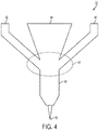
- FIG. 4 shows a more detailed embodiment of an embodiment of a flow focusing section 32.
- the flow focusing section here provides merely one embodiment of a flow focusing section.
- the flow focusing section creates a coaxial flow of a material stream of sheathing fluids entering the section through channels 40 and 42, which will sheath the main fluid flow coming into channel 44.
- the sheathing occurs at region 46 where the flows come together. This highly extensional flow aligns particles, which will be important as discussed in more detail further.
- the flow focusing section may be followed by a reactive bonding section 32 as shown in Figure 5 .
- This section may be optional depending upon the materials used.
- One result of the reactive bonding section is a linking of the particles to form particles of varying lengths.
- the bonding will typically result from application of a stimulus 52.
- the stimulus may involve the application of heat or light, such as with a pulsed laser or localized heating.
- the fibers may vary in length from several hundred nanometers to millimeters. This achieves parity with existing Stable Free Radical Polymerization (SFRP) approaches.
- SFRP Stable Free Radical Polymerization
- This approach may be applied to various types of colloids for which functionalization chemistries are known including silica, clays, graphene and hydroxyapatite.
- a mixer 30 Prior to the flow focusing section and the reactive bonding section, a mixer 30 mixes up the base materials. Modulating resin composition or fiber content may be achieved by using multi-layer mixers, which also make particle alignment possible.
- fluidic systems for fiber orientation can control the straining axes of the flow.
- One of the most prevalent methods to control the straining axes in a flow is to use a four roll mill as shown in Figure 5 . In a four roll system such as 54 the straining axes of the flow are controlled by changing the rotation rate of the four cylinders.
- a linear flow ranging from pure rotation to pure extension can be generated. Fibers align along the principal straining axis in a purely extensional flow. By adding more rotation to the flow, the extensional axes are brought closer together.
- the mixer has specific performance characteristics that are compatible with digitally modulated material composition.
- the mixer will have the ability to modulate composition in a volume no larger than the characteristic voxel size, perform complete mixing in the volume in roughly the time required to deposit a voxel of material at the desired material deposition rate or staging of materials in such a way that mixing is complete before material deposition.
- the mixer will have negligible material retention and a near uniform residence time in the mixing chamber to eliminate axial dispersion or cross-contamination of subsequent voxels.
- a fluidic equivalent of the four roll mill can be realized using carefully controlled fluidic inlet/outlet elements as shown in Figure 7 .
- the inlets 58 and 60 receive the material and outlets 62 and 64 similar to the areas around the cylinders of the four roll mill. Fibers will generally orient along the principal axis, the degree of rotation in the flow can be used to control fiber rotation from pure rotation to pure extension. This is merely one example of a fluidic inlet/outlet elements, other embodiments will apply within the embodiments here.
- Figure 8 shows how modulating the flow type parameter can change the principal straining axis.
- the degree of rotation of the flow is characterized by the parameter ⁇ that ranges from -1 indicating pure rotation and + 1 indicating pure extension.
- a fiber undergoing the flows is shown as the darker line.
- the slots at the ends of the channel serve as the fluidic inlets/outlets for the flow orientation system. Fibers transported down the central circular channel will decelerate and orient parallel to the exit plane as they enter the inlet/outlet region. The mixed flow generated at the junction contributes to the deceleration but primarily rotates the fiber until it orients along the principal straining axis. This axis is controlled by the flow parameter, which is modulated by appropriately choosing inlet and outlet flow rates in the slots.
- the fluidic channel system 80 is designed to control fiber orientation.
- the slots 86 and 88 are the inlets for the orienting flow, and the slots 82 and 84 are the outlets as shown in the cutaway view.
- the fiber orientation can be dynamically modulated at any given point in space by varying the mixed flow control profile just prior to extrusion.
- the flow in the slots is stopped and the fiber is deposited in a direction parallel to the nozzle. Orientation control of these larger fibers is possible when the print head is coupled to a three-dimensional deposition tool, such as the actuator 18 of Figure 2 .
- the oriented particles are deposited in a three-dimensional digital manner in order to facilitate arbitrary particle alignment and material composition.
- the system of Figure 1 has a flexibility that makes it possible to vary fiber orientation and concentration in a nearly arbitrary manner using different techniques depending on the fiber scale.
- the deposition has the ability to dynamically change the angle of deposition relative to the substrate.
- the actuator 18 of Figure 2 moves through all 6 axes.
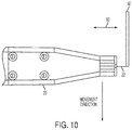
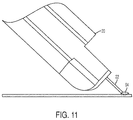
- Figures 10 and 11 show views of the exit nozzle.
- Figure 10 shows a view from above the nozzle as it deposits a fiber larger than the exit orifice.
- Figure 11 shows a view of a cross section perpendicular to the direction of motion of the nozzle.
- the choice of resin is an important parameter in enabling a digital workflow.
- the resin may be UV-curable thermoset polymers that utilize acrylate linking groups bonded to traditional thermoset monomers. These polymers possess many of the positive qualities of traditional thermosets but with the ease of UV processing. These chemistries make digital structures possible using rasterized deposition followed by partial UV curing in a manner similar to existing inkjet-based three-dimensional printing.
- the system could use non-UV thermoset chemistry, such as an epoxy.
- This system allows for unprecedented control of fiber orientation and concentration. This system also allows for digital tailoring of mechanical properties via the use of hierarchical resin systems employing variable amorphous and crystalline polymer domains and/or nanocomposite reinforcement used in combination with macroscopic fiber reinforcement.
Landscapes
- Engineering & Computer Science (AREA)
- Chemical & Material Sciences (AREA)
- Materials Engineering (AREA)
- Manufacturing & Machinery (AREA)
- Physics & Mathematics (AREA)
- Mechanical Engineering (AREA)
- Optics & Photonics (AREA)
- Ceramic Engineering (AREA)
- Civil Engineering (AREA)
- Composite Materials (AREA)
- Structural Engineering (AREA)
- Plasma & Fusion (AREA)
Abstract
Description
- This disclosure relates to fabrication of multi-scale heterogeneous materials, more particularly to fabrication of these materials from colloidal elements using a microfluidic print head and a robotic deposition system.
- Fabricating hierarchical, multi-material structures offers tremendous promise for controlling and tailoring material properties. An example that highlights both the potential and the challenges of hierarchical, multi-material structures is discussed in "Simultaneously High Stiffness and Damping in Nanoengineered Microtruss Composites," ACS Nano, March 12, 2014, pp. 3468-3475. The microtruss composite possesses the contradictory design goals of high stiffness and high damping. These structures have sound absorbing qualities in cars and airplanes while also being strong. Fabrication of these structures involves the growing of carbon nanotubes (CNTs) from a steel plate and coating with alumina using traditional semiconductor processes, followed by multiple deposition steps to build a polyurethane/clay layer on the CNTs and finally encapsulation with polyurethane. This material is graded with the interface between the polymer and CNT microtruss composed of a nano-composite polymer that has intermediate properties, which is important for overall mechanical robustness. However, this method is not scalable to large areas or digital.
-
US Patent Publication 2011/0079936, to Oxman , explores concepts on digitally printing graded materials using dye in a FDM (fused deposition modeling) print head. The disclosure teaches 'on the fly' blending of materials for creating continuous gradients in material properties. However, this concept does not have the capability to build multiscale structures or heterogeneous material structures required to achieve the full potential of architected materials. - Embodiments include a method to fabricate hierarchical graded materials include providing a reservoir of functionalized particles, mixing at least some of the functionalized particles using a mixer in the print head having a mixed fluid volume control on an order of a voxel to produce mixed functionalized particles, and actuating a print head to deposit the mixed functionalized particles on a substrate.
-
-
Figure 1 shows a graph illustrating an example of hierarchical graded material. -
Figure 2 shows an embodiment of a system to fabricate hierarchical graded materials. -
Figure 3 shows a block diagram of a print head in a system to fabricated hierarchical graded materials. -
Figure 4 shows an embodiment of a flow focusing section of a print head. -
Figure 5 shows an embodiment of a reactive bonding section of a print head. -
Figure 6 shows a diagram of a four roll mill. -
Figure 7 shows a diagram of an embodiment of an inlet/outlet element equivalent to a four roll mill. -
Figure 8 show flow diagrams of modulation of a principal axis of orientation. -
Figure 9 shows views of an embodiment of an inlet/outlet component. -
Figures10-11 views of an exit nozzle of a print head. - The following discussion will use several terms that have particular meanings when used here. A 'hierarchical material' is a material having structures spanning multiple orders of magnitude of length scale. A 'graded material' is a material having a continuous and smooth spatial gradient of composition. A 'digital material' has controlled spatial composition and form. The unit of a digital material is a voxel, which is a three-dimensional droplet or characteristic volume of material. A 'multi-material composite' is a material composed of a suspending material, usually a polymer, also known as a resin, and a dispersed particulate reinforcing material. The reinforcing material may comprise of colloidal clays, carbon nanotubes, or macroscopic additives like carbon fibers or ceramic platelets.
- Merely as an example to illustrate materials that have some of these properties, polyurethane-based composites have been formulated that are hierarchically reinforced with hard polymeric crystalline domains, laponite nanoplatelets and alumina microplatelets at progressively larger length scales. By controlling the concentration of such building blocks within the polymer matrix, it is possible to change the elastic modulus of polyurethane-based composites within a very broad range spanning over four orders of magnitude.
Figure 1 shows a graph of this material. Extreme gradients in mechanical properties within the same material approaches the range of elastic moduli found in highly graded natural composites and is far beyond the span of properties obtainable in metal/ceramic functionally graded materials. This graph is from a paper, "Biological and Bioinspired Composites with Spatially Tunable Heterogeneous Architectures," Advanced Functional Materials, 2013, by Professor A. R. Studart, (www.wileyonlinelibrary.com). -
Figure 2 shows an embodiment of a system to digitally fabricate multi-scale, or hierarchical, heterogeneous materials using novel microfluidic print heads coupled to colloidal manipulation chemistry and a robotic deposition system. The system may take many forms and the embodiment ofFigure 2 is merely one example. The embodiment ofFigure 2 has areservoir 12 in which functional colloidal particles are provided to the print head to be printed on the final substrate. An umbilical or conduit such as 14 allows the material to flow from the reservoir to a local reservoir attached to the print head. Acontroller 16 will regulate the flow of the material to the print head and the motion of theactuator 18. - The
actuator 18 has the capability to move theprint head 20 in 6 axes of motion, forward/backward, up/down, left/right, on the three perpendicular axes, as well as the three rotational axes, also known as pitch, yaw and roll. This facilitates both the mixing and oriented deposition as will be discussed in more detail later. Theprint head 20 will typically have multiple nozzles, such as 22, to allow deposition of the materials. - The mixer that has a desired output of a continuous profile of composition versus time. The changes in composition occur at a spatial resolution equal to a voxel. This change in composition has implications for the volume residence time and residence time distribution. The 'residence time' is the time between the functional materials entering the print head and exiting the nozzle. The residence time varies for different materials as they move through the print head at different rates. The 'residence time distribution' (RTD) of a chemical reactor is a probability distribution function that describes the amount of time a fluid element could spend inside the reactor. The below discussion is merely an illustrative example and is in no way intended to limit the embodiments disclosed here.
- In this example, an output of the printer is assumed to be a line of material with a square cross section that has a height and width equal to the voxel size, which is 100 microns (1e-4m). The discussion also assumes that the linear deposition rate is 1 cm/s or 1e4 microns/sec, or 100 voxels/second. Each voxel has a specified composition state, specifically by a volume percentage of material A and B, as examples. Each voxel must have a composition that is homogeneously mixed and defined. "Homogeneously mixed" means materials A and B are homogeneously distributed through the voxel such that there are no localized areas in the voxel with a higher or lower amount of A and B than what is desired in the voxel overall. "Defined" means that the specified composition and the actual composition of the voxel are the same.
- For the voxel to be homogeneously mixed, the mixer should be able to process a single voxel of a material that is a 100 x 100 x 100 micron cube and fully mix it in the time required to deposit the material at a rate of 100 voxels/sec, 0.01 seconds. Alternatively, the mixer must be able to 'queue' a number of voxels and mix them in such a way that each 100 x 100 x 100 micron cube of material that exits the mixer is at the specified composition state desired in the part buildup. This latter configuration relaxes the mixing speed requirement, the time for mixing now is the residence time of a specific voxel in the mixer, which is the number of voxels in the mixer divided by the deposition rate. If the mixer processes 100 voxels at a time, the mixing time becomes 1 second, which is more reasonable, especially for viscous liquids.
- Mixing multiple voxels presents challenges for typical mixing techniques such as static or screw mixers. While this mixers achieve highly effective mixing through multiple folding, stretching and cutting operations, they also have a wide range of fluid residence times. This range of residence times results from the tortuous streamlines and near-zero flow regions within the mixer. Particles or fluid elements that sample these parts of the flow field typically have long residence times. In practice, this means that a square pulse of fluid dye typically exits the mixer with a residence time distribution that has a long tail of material that samples these low flow or tortuous path regions.
- This long tail is problematic as it pollutes the voxel immediately after the one being mixed. Over many voxels, the residual material from each voxel mixing operation using a mixer with a typical RTD will cause the voxel composition to deviate significantly from what is specified, and the voxel will not be defined. Therefore, the mixer should mix materials in such a way that the RTD has no tail. Quantitatively, the RTD must be on the order of the voxel residence time itself. In this example, the RTD should be 0.01 seconds.
- There are several mixing techniques that could attain both of these criteria. For example, high parallelized mixing chambers that are actuated using flexible valves, such as those employed by Quake, or acoustics could achieve both small mixing volumes with mixing and tight residence time distributions as defined above. However, these techniques have not been demonstrated using highly viscous liquids of interest to additive manufacturing.
- The
reservoir 12 contains functionalized particles. Using anisotropic platelets or other colloidal building blocks, different functional groups on different faces of the particle can drive interactions and assembly in a prescribed manner. The anisotropic particles may consist of platelets, chiplets, wires, etc., all of which will be referred to here as fibers. Control of the selection of the functional group on the fibers enables explicit cross-linking of colloids to each other in controlled morphologies. Using one reactive group and reaction of the resulting fibers with the resin of another achieves strong interfacial contact between the particles and matrix to provide mechanical performance. - As an example, the system can direct assembly of engineered multi-particles structures where different particles are connected in a prescribed manner as dictated by keying chemistry. This would allow creation of multi-scale reinforcement materials using chiral particles, with the chirality a function of both the particle anisotropic and keying chemistry. Chirality may enable large-scale ordering of the particles in a manner analogous to collagen fibrils seen in bone.
- Examples of printable particle-reinforced composites can be found in a paper by Brent Compton and Jennifer Lewis "Printing of Lightweight Cellular Composites," Advanced Material, Vol. 26, pp. 5930-5935, 2014 and in the Army Research Lab technical report "Micro-composite fabrication via Field-Aided Laminar Composite (FALCom) Processing", ARL-TR-6106, September 2012. In the FalCOM system, fibers are deposited using a nozzle and then aligned using electric fields. This process is not ideal since the electrical fields required are high (kV/mm) and the particle alignment times in viscous polymeric media are on the order of 1-10s which slows overall processing speed. Lewis's work uses a much simpler extensional flow nozzle to attain particle alignment in a direction parallel to the nozzle. In the embodiments here, arbitrary particle alignment is obtained fluidically, combining the best attributes of both of these prior art systems for controlled reinforcement deposition.
-
Figure 3 shows a more detailed view of theprint head 20. The print head comprises amixer section 30, a possibleflow focusing section 32, and optional reactive bonding and fluidic particle alignment sections, 34 and 36. Each of these will be discussed in more detail in turn. -
Figure 4 shows a more detailed embodiment of an embodiment of aflow focusing section 32. The flow focusing section here provides merely one embodiment of a flow focusing section. In the embodiment ofFigure 4 , the flow focusing section creates a coaxial flow of a material stream of sheathing fluids entering the section throughchannels channel 44. The sheathing occurs atregion 46 where the flows come together. This highly extensional flow aligns particles, which will be important as discussed in more detail further. - The flow focusing section may be followed by a
reactive bonding section 32 as shown inFigure 5 . This section may be optional depending upon the materials used. One result of the reactive bonding section is a linking of the particles to form particles of varying lengths. The bonding will typically result from application of astimulus 52. The stimulus may involve the application of heat or light, such as with a pulsed laser or localized heating. By modulating the duration of the stimulus, and the flow of the building block material, the fibers may vary in length from several hundred nanometers to millimeters. This achieves parity with existing Stable Free Radical Polymerization (SFRP) approaches. This approach may be applied to various types of colloids for which functionalization chemistries are known including silica, clays, graphene and hydroxyapatite. - Prior to the flow focusing section and the reactive bonding section, a
mixer 30 mixes up the base materials. Modulating resin composition or fiber content may be achieved by using multi-layer mixers, which also make particle alignment possible. For fibers that are smaller than the orifice size (approximately 50-100 microns), fluidic systems for fiber orientation can control the straining axes of the flow. One of the most prevalent methods to control the straining axes in a flow is to use a four roll mill as shown inFigure 5 . In a four roll system such as 54 the straining axes of the flow are controlled by changing the rotation rate of the four cylinders. A linear flow ranging from pure rotation to pure extension can be generated. Fibers align along the principal straining axis in a purely extensional flow. By adding more rotation to the flow, the extensional axes are brought closer together. - As mentioned above, the flow focusing, reactive bonding, and fluidic particle alignment sections are optional. The mixer has specific performance characteristics that are compatible with digitally modulated material composition. The mixer will have the ability to modulate composition in a volume no larger than the characteristic voxel size, perform complete mixing in the volume in roughly the time required to deposit a voxel of material at the desired material deposition rate or staging of materials in such a way that mixing is complete before material deposition. The mixer will have negligible material retention and a near uniform residence time in the mixing chamber to eliminate axial dispersion or cross-contamination of subsequent voxels.
- A fluidic equivalent of the four roll mill can be realized using carefully controlled fluidic inlet/outlet elements as shown in
Figure 7 . Theinlets outlets -
Figure 8 shows how modulating the flow type parameter can change the principal straining axis. The degree of rotation of the flow is characterized by the parameter α that ranges from -1 indicating pure rotation and + 1 indicating pure extension. InFigure 8 , diagram 66 shows an orientation angle, θ, of 11.25° where α = 0.040. Diagram 68 shows an orientation angle, θ, of 22.5° where α = 0.172. Finally, diagram 70 shows an orientation angle, θ, of 45° where α = 1.0. A fiber undergoing the flows is shown as the darker line. - An example of an inlet/outlet control element that can implement this type of flow control. The slots at the ends of the channel serve as the fluidic inlets/outlets for the flow orientation system. Fibers transported down the central circular channel will decelerate and orient parallel to the exit plane as they enter the inlet/outlet region. The mixed flow generated at the junction contributes to the deceleration but primarily rotates the fiber until it orients along the principal straining axis. This axis is controlled by the flow parameter, which is modulated by appropriately choosing inlet and outlet flow rates in the slots.
- In
Figure 9 , thefluidic channel system 80 is designed to control fiber orientation. Theslots slots 82 and 84 are the outlets as shown in the cutaway view. For fibers smaller than the deposition orifice, the fiber orientation can be dynamically modulated at any given point in space by varying the mixed flow control profile just prior to extrusion. For larger fibers, the flow in the slots is stopped and the fiber is deposited in a direction parallel to the nozzle. Orientation control of these larger fibers is possible when the print head is coupled to a three-dimensional deposition tool, such as theactuator 18 ofFigure 2 . - The oriented particles are deposited in a three-dimensional digital manner in order to facilitate arbitrary particle alignment and material composition. The system of
Figure 1 has a flexibility that makes it possible to vary fiber orientation and concentration in a nearly arbitrary manner using different techniques depending on the fiber scale. The deposition has the ability to dynamically change the angle of deposition relative to the substrate. Theactuator 18 ofFigure 2 moves through all 6 axes. - Depending on the fiber length and nozzle diameters, some fibers may not be able to flow through the nozzle without deviating from their target orientation. In those instances, the orientation of the exit nozzle is altered, regardless of the direction of the movement.
Figures 10 and11 show views of the exit nozzle.Figure 10 shows a view from above the nozzle as it deposits a fiber larger than the exit orifice.Figure 11 shows a view of a cross section perpendicular to the direction of motion of the nozzle. - In some applications, the choice of resin is an important parameter in enabling a digital workflow. In one embodiment, the resin may be UV-curable thermoset polymers that utilize acrylate linking groups bonded to traditional thermoset monomers. These polymers possess many of the positive qualities of traditional thermosets but with the ease of UV processing. These chemistries make digital structures possible using rasterized deposition followed by partial UV curing in a manner similar to existing inkjet-based three-dimensional printing. Alternatively, the system could use non-UV thermoset chemistry, such as an epoxy.
- This system allows for unprecedented control of fiber orientation and concentration. This system also allows for digital tailoring of mechanical properties via the use of hierarchical resin systems employing variable amorphous and crystalline polymer domains and/or nanocomposite reinforcement used in combination with macroscopic fiber reinforcement.
- It will be appreciated that variants of the above-disclosed and other features and functions, or alternatives thereof, may be combined into many other different systems or applications. Various presently unforeseen or unanticipated alternatives, modifications, variations, or improvements therein may be subsequently made by those skilled in the art which are also intended to be encompassed by the following claims.
Claims (10)
- A method to fabricate hierarchical graded materials, comprising:providing a reservoir of functionalized particles;mixing at least some of the functionalized particles using a mixer in the print head having a mixed fluid volume control on an order of a voxel to produce mixed functionalized particles; andactuating a print head to deposit the mixed functionalized particles on a substrate.
- The method of claim 1, further comprising applying a stimulus to the mixed functionalized particles to reactively bond the functionalized particles.
- The method of claim 2, wherein applying a stimulus comprises applying one of either heat or light.
- The method of claim 1, further comprising focusing a flow of the mixed functionalized particles.
- The method of claim 4, wherein focusing a flow comprises creating a coaxial flow of materials.
- The method of claim 5, wherein creating a coaxial flow of materials comprises applying a sheathing fluid to outer channels of a flow focusing section and applying a main fluid to a central channel.
- The method of claim 1, further comprising fluidic particle alignment.
- The method of claim 7, wherein fluidic particle alignment comprises altering an angle of deposition based upon a scale of the particles.
- The method of claim 1, wherein providing a reservoir of functionalized particles comprises providing a reservoir of at least one of anisotropic platelets, chiplets, wires, fibers, and colloidal building blocks.
- A method to fabricate hierarchical graded materials, comprising:providing a reservoir of functionalized particles;mixing at least some of the functionalized particles using a mixer in the print head mixer in the print head having a mixed fluid volume control on an order of a voxel to produce mixed functionalized particles; andactuating a print head to deposit the mixed functionalized particles on a substrate at an angle of deposition determined by a scale of the particles.
Applications Claiming Priority (1)
| Application Number | Priority Date | Filing Date | Title |
|---|---|---|---|
| US14/578,071 US9821339B2 (en) | 2014-12-19 | 2014-12-19 | System and method for digital fabrication of graded, hierarchical material structures |
Publications (2)
| Publication Number | Publication Date |
|---|---|
| EP3040188A1 true EP3040188A1 (en) | 2016-07-06 |
| EP3040188B1 EP3040188B1 (en) | 2020-09-16 |
Family
ID=55066294
Family Applications (1)
| Application Number | Title | Priority Date | Filing Date |
|---|---|---|---|
| EP15198480.4A Active EP3040188B1 (en) | 2014-12-19 | 2015-12-08 | Method for digital additive manufacturing of graded, hierarchical material structures |
Country Status (3)
| Country | Link |
|---|---|
| US (1) | US9821339B2 (en) |
| EP (1) | EP3040188B1 (en) |
| JP (1) | JP6574692B2 (en) |
Cited By (1)
| Publication number | Priority date | Publication date | Assignee | Title |
|---|---|---|---|---|
| CN108016017A (en) * | 2017-12-01 | 2018-05-11 | 北京科技大学 | Static stretch mixer and its method for being used to prepare polymer nanocomposites |
Families Citing this family (104)
| Publication number | Priority date | Publication date | Assignee | Title |
|---|---|---|---|---|
| KR20170019366A (en) | 2014-05-16 | 2017-02-21 | 디버전트 테크놀로지스, 인크. | Modular formed nodes for vehicle chassis and their methods of use |
| JP6820843B2 (en) | 2014-07-02 | 2021-01-27 | ダイバージェント テクノロジーズ, インコーポレイテッドDivergent Technologies, Inc. | Systems and methods for manufacturing fittings |
| US9486960B2 (en) | 2014-12-19 | 2016-11-08 | Palo Alto Research Center Incorporated | System for digital fabrication of graded, hierarchical material structures |
| US10173255B2 (en) | 2016-06-09 | 2019-01-08 | Divergent Technologies, Inc. | Systems and methods for arc and node design and manufacture |
| US11155005B2 (en) | 2017-02-10 | 2021-10-26 | Divergent Technologies, Inc. | 3D-printed tooling and methods for producing same |
| US10759090B2 (en) | 2017-02-10 | 2020-09-01 | Divergent Technologies, Inc. | Methods for producing panels using 3D-printed tooling shells |
| US10519740B2 (en) | 2017-03-20 | 2019-12-31 | Weatherford Technology Holdings, Llc | Sealing apparatus and associated methods of manufacturing |
| US10472911B2 (en) | 2017-03-20 | 2019-11-12 | Weatherford Technology Holdings, LLC. | Gripping apparatus and associated methods of manufacturing |
| US12251884B2 (en) | 2017-04-28 | 2025-03-18 | Divergent Technologies, Inc. | Support structures in additive manufacturing |
| US10898968B2 (en) | 2017-04-28 | 2021-01-26 | Divergent Technologies, Inc. | Scatter reduction in additive manufacturing |
| US10703419B2 (en) | 2017-05-19 | 2020-07-07 | Divergent Technologies, Inc. | Apparatus and methods for joining panels |
| US11358337B2 (en) | 2017-05-24 | 2022-06-14 | Divergent Technologies, Inc. | Robotic assembly of transport structures using on-site additive manufacturing |
| US11123973B2 (en) | 2017-06-07 | 2021-09-21 | Divergent Technologies, Inc. | Interconnected deflectable panel and node |
| US10919230B2 (en) | 2017-06-09 | 2021-02-16 | Divergent Technologies, Inc. | Node with co-printed interconnect and methods for producing same |
| US10781846B2 (en) | 2017-06-19 | 2020-09-22 | Divergent Technologies, Inc. | 3-D-printed components including fasteners and methods for producing same |
| US10994876B2 (en) | 2017-06-30 | 2021-05-04 | Divergent Technologies, Inc. | Automated wrapping of components in transport structures |
| US11022375B2 (en) | 2017-07-06 | 2021-06-01 | Divergent Technologies, Inc. | Apparatus and methods for additively manufacturing microtube heat exchangers |
| US10895315B2 (en) | 2017-07-07 | 2021-01-19 | Divergent Technologies, Inc. | Systems and methods for implementing node to node connections in mechanized assemblies |
| US10751800B2 (en) | 2017-07-25 | 2020-08-25 | Divergent Technologies, Inc. | Methods and apparatus for additively manufactured exoskeleton-based transport structures |
| US10940609B2 (en) | 2017-07-25 | 2021-03-09 | Divergent Technologies, Inc. | Methods and apparatus for additively manufactured endoskeleton-based transport structures |
| US10605285B2 (en) | 2017-08-08 | 2020-03-31 | Divergent Technologies, Inc. | Systems and methods for joining node and tube structures |
| US10357959B2 (en) | 2017-08-15 | 2019-07-23 | Divergent Technologies, Inc. | Methods and apparatus for additively manufactured identification features |
| US11306751B2 (en) | 2017-08-31 | 2022-04-19 | Divergent Technologies, Inc. | Apparatus and methods for connecting tubes in transport structures |
| US10960611B2 (en) | 2017-09-06 | 2021-03-30 | Divergent Technologies, Inc. | Methods and apparatuses for universal interface between parts in transport structures |
| US11292058B2 (en) | 2017-09-12 | 2022-04-05 | Divergent Technologies, Inc. | Apparatus and methods for optimization of powder removal features in additively manufactured components |
| US10668816B2 (en) | 2017-10-11 | 2020-06-02 | Divergent Technologies, Inc. | Solar extended range electric vehicle with panel deployment and emitter tracking |
| US10814564B2 (en) | 2017-10-11 | 2020-10-27 | Divergent Technologies, Inc. | Composite material inlay in additively manufactured structures |
| US11786971B2 (en) | 2017-11-10 | 2023-10-17 | Divergent Technologies, Inc. | Structures and methods for high volume production of complex structures using interface nodes |
| US10926599B2 (en) | 2017-12-01 | 2021-02-23 | Divergent Technologies, Inc. | Suspension systems using hydraulic dampers |
| US11110514B2 (en) | 2017-12-14 | 2021-09-07 | Divergent Technologies, Inc. | Apparatus and methods for connecting nodes to tubes in transport structures |
| US11085473B2 (en) | 2017-12-22 | 2021-08-10 | Divergent Technologies, Inc. | Methods and apparatus for forming node to panel joints |
| US11534828B2 (en) | 2017-12-27 | 2022-12-27 | Divergent Technologies, Inc. | Assembling structures comprising 3D printed components and standardized components utilizing adhesive circuits |
| US11420262B2 (en) | 2018-01-31 | 2022-08-23 | Divergent Technologies, Inc. | Systems and methods for co-casting of additively manufactured interface nodes |
| US10751934B2 (en) | 2018-02-01 | 2020-08-25 | Divergent Technologies, Inc. | Apparatus and methods for additive manufacturing with variable extruder profiles |
| US11224943B2 (en) | 2018-03-07 | 2022-01-18 | Divergent Technologies, Inc. | Variable beam geometry laser-based powder bed fusion |
| US11267236B2 (en) | 2018-03-16 | 2022-03-08 | Divergent Technologies, Inc. | Single shear joint for node-to-node connections |
| US11872689B2 (en) | 2018-03-19 | 2024-01-16 | Divergent Technologies, Inc. | End effector features for additively manufactured components |
| US11254381B2 (en) | 2018-03-19 | 2022-02-22 | Divergent Technologies, Inc. | Manufacturing cell based vehicle manufacturing system and method |
| US11408216B2 (en) | 2018-03-20 | 2022-08-09 | Divergent Technologies, Inc. | Systems and methods for co-printed or concurrently assembled hinge structures |
| US11613078B2 (en) | 2018-04-20 | 2023-03-28 | Divergent Technologies, Inc. | Apparatus and methods for additively manufacturing adhesive inlet and outlet ports |
| US11214317B2 (en) | 2018-04-24 | 2022-01-04 | Divergent Technologies, Inc. | Systems and methods for joining nodes and other structures |
| US10682821B2 (en) | 2018-05-01 | 2020-06-16 | Divergent Technologies, Inc. | Flexible tooling system and method for manufacturing of composite structures |
| US11020800B2 (en) | 2018-05-01 | 2021-06-01 | Divergent Technologies, Inc. | Apparatus and methods for sealing powder holes in additively manufactured parts |
| US11389816B2 (en) | 2018-05-09 | 2022-07-19 | Divergent Technologies, Inc. | Multi-circuit single port design in additively manufactured node |
| US10691104B2 (en) | 2018-05-16 | 2020-06-23 | Divergent Technologies, Inc. | Additively manufacturing structures for increased spray forming resolution or increased fatigue life |
| US11590727B2 (en) | 2018-05-21 | 2023-02-28 | Divergent Technologies, Inc. | Custom additively manufactured core structures |
| US11441586B2 (en) | 2018-05-25 | 2022-09-13 | Divergent Technologies, Inc. | Apparatus for injecting fluids in node based connections |
| US11035511B2 (en) | 2018-06-05 | 2021-06-15 | Divergent Technologies, Inc. | Quick-change end effector |
| US11292056B2 (en) | 2018-07-06 | 2022-04-05 | Divergent Technologies, Inc. | Cold-spray nozzle |
| US10947419B2 (en) | 2018-07-23 | 2021-03-16 | Palo Alto Research Center Incorporated | Method for joining dissimilar materials |
| US11269311B2 (en) | 2018-07-26 | 2022-03-08 | Divergent Technologies, Inc. | Spray forming structural joints |
| US10836120B2 (en) | 2018-08-27 | 2020-11-17 | Divergent Technologies, Inc . | Hybrid composite structures with integrated 3-D printed elements |
| US11433557B2 (en) | 2018-08-28 | 2022-09-06 | Divergent Technologies, Inc. | Buffer block apparatuses and supporting apparatuses |
| US11826953B2 (en) | 2018-09-12 | 2023-11-28 | Divergent Technologies, Inc. | Surrogate supports in additive manufacturing |
| US11072371B2 (en) | 2018-10-05 | 2021-07-27 | Divergent Technologies, Inc. | Apparatus and methods for additively manufactured structures with augmented energy absorption properties |
| US11260582B2 (en) | 2018-10-16 | 2022-03-01 | Divergent Technologies, Inc. | Methods and apparatus for manufacturing optimized panels and other composite structures |
| US12115583B2 (en) | 2018-11-08 | 2024-10-15 | Divergent Technologies, Inc. | Systems and methods for adhesive-based part retention features in additively manufactured structures |
| US12194536B2 (en) | 2018-11-13 | 2025-01-14 | Divergent Technologies, Inc. | 3-D printer with manifolds for gas exchange |
| US11504912B2 (en) | 2018-11-20 | 2022-11-22 | Divergent Technologies, Inc. | Selective end effector modular attachment device |
| USD911222S1 (en) | 2018-11-21 | 2021-02-23 | Divergent Technologies, Inc. | Vehicle and/or replica |
| US10663110B1 (en) | 2018-12-17 | 2020-05-26 | Divergent Technologies, Inc. | Metrology apparatus to facilitate capture of metrology data |
| US11529741B2 (en) | 2018-12-17 | 2022-12-20 | Divergent Technologies, Inc. | System and method for positioning one or more robotic apparatuses |
| US11449021B2 (en) | 2018-12-17 | 2022-09-20 | Divergent Technologies, Inc. | Systems and methods for high accuracy fixtureless assembly |
| US11885000B2 (en) | 2018-12-21 | 2024-01-30 | Divergent Technologies, Inc. | In situ thermal treatment for PBF systems |
| EP3898746B1 (en) * | 2018-12-21 | 2023-02-08 | Sika Technology AG | Method for 3d printing of curable two-component polyurethane compositions |
| US12378643B2 (en) | 2019-01-18 | 2025-08-05 | Divergent Technologies, Inc. | Aluminum alloys |
| US11203240B2 (en) | 2019-04-19 | 2021-12-21 | Divergent Technologies, Inc. | Wishbone style control arm assemblies and methods for producing same |
| US12314031B1 (en) | 2019-06-27 | 2025-05-27 | Divergent Technologies, Inc. | Incorporating complex geometric features in additively manufactured parts |
| US12280554B2 (en) | 2019-11-21 | 2025-04-22 | Divergent Technologies, Inc. | Fixtureless robotic assembly |
| US11912339B2 (en) | 2020-01-10 | 2024-02-27 | Divergent Technologies, Inc. | 3-D printed chassis structure with self-supporting ribs |
| US11590703B2 (en) | 2020-01-24 | 2023-02-28 | Divergent Technologies, Inc. | Infrared radiation sensing and beam control in electron beam additive manufacturing |
| US11884025B2 (en) | 2020-02-14 | 2024-01-30 | Divergent Technologies, Inc. | Three-dimensional printer and methods for assembling parts via integration of additive and conventional manufacturing operations |
| US11479015B2 (en) | 2020-02-14 | 2022-10-25 | Divergent Technologies, Inc. | Custom formed panels for transport structures and methods for assembling same |
| US12194674B2 (en) | 2020-02-14 | 2025-01-14 | Divergent Technologies, Inc. | Multi-material powder bed fusion 3-D printer |
| US12203397B2 (en) | 2020-02-18 | 2025-01-21 | Divergent Technologies, Inc. | Impact energy absorber with integrated engine exhaust noise muffler |
| US11421577B2 (en) | 2020-02-25 | 2022-08-23 | Divergent Technologies, Inc. | Exhaust headers with integrated heat shielding and thermal syphoning |
| US11535322B2 (en) | 2020-02-25 | 2022-12-27 | Divergent Technologies, Inc. | Omni-positional adhesion device |
| US12337541B2 (en) | 2020-02-27 | 2025-06-24 | Divergent Technologies, Inc. | Powder bed fusion additive manufacturing system with desiccant positioned within hopper and ultrasonic transducer |
| US11413686B2 (en) | 2020-03-06 | 2022-08-16 | Divergent Technologies, Inc. | Methods and apparatuses for sealing mechanisms for realizing adhesive connections with additively manufactured components |
| KR20230035571A (en) | 2020-06-10 | 2023-03-14 | 디버전트 테크놀로지스, 인크. | Adaptive production system |
| US11850804B2 (en) | 2020-07-28 | 2023-12-26 | Divergent Technologies, Inc. | Radiation-enabled retention features for fixtureless assembly of node-based structures |
| US11806941B2 (en) | 2020-08-21 | 2023-11-07 | Divergent Technologies, Inc. | Mechanical part retention features for additively manufactured structures |
| CN116457139A (en) | 2020-09-08 | 2023-07-18 | 戴弗根特技术有限公司 | Assembly sequence generation |
| CN116669885A (en) | 2020-09-22 | 2023-08-29 | 戴弗根特技术有限公司 | Method and apparatus for ball milling to produce powders for additive manufacturing |
| US12220819B2 (en) | 2020-10-21 | 2025-02-11 | Divergent Technologies, Inc. | 3-D printed metrology feature geometry and detection |
| US12311612B2 (en) | 2020-12-18 | 2025-05-27 | Divergent Technologies, Inc. | Direct inject joint architecture enabled by quick cure adhesive |
| US12083596B2 (en) | 2020-12-21 | 2024-09-10 | Divergent Technologies, Inc. | Thermal elements for disassembly of node-based adhesively bonded structures |
| US12226824B2 (en) | 2020-12-22 | 2025-02-18 | Divergent Technologies, Inc. | Three dimensional printer with configurable build plate for rapid powder removal |
| US11752554B2 (en) | 2020-12-24 | 2023-09-12 | Xerox Corporation | Methods and systems for printing graded materials by roller-based deposition of multiple powders |
| US11872626B2 (en) | 2020-12-24 | 2024-01-16 | Divergent Technologies, Inc. | Systems and methods for floating pin joint design |
| US11947335B2 (en) | 2020-12-30 | 2024-04-02 | Divergent Technologies, Inc. | Multi-component structure optimization for combining 3-D printed and commercially available parts |
| US11928966B2 (en) | 2021-01-13 | 2024-03-12 | Divergent Technologies, Inc. | Virtual railroad |
| US12249812B2 (en) | 2021-01-19 | 2025-03-11 | Divergent Technologies, Inc. | Bus bars for printed structural electric battery modules |
| US12459377B2 (en) | 2021-01-19 | 2025-11-04 | Divergent Technologies, Inc. | Energy unit cells for primary vehicle structure |
| US20220288850A1 (en) | 2021-03-09 | 2022-09-15 | Divergent Technologies, Inc. | Rotational additive manufacturing systems and methods |
| US12090551B2 (en) | 2021-04-23 | 2024-09-17 | Divergent Technologies, Inc. | Removal of supports, and other materials from surface, and within hollow 3D printed parts |
| US12138772B2 (en) | 2021-04-30 | 2024-11-12 | Divergent Technologies, Inc. | Mobile parts table |
| CN117769486A (en) | 2021-05-24 | 2024-03-26 | 戴弗根特技术有限公司 | Robotic gripper equipment |
| WO2023278878A1 (en) | 2021-07-01 | 2023-01-05 | Divergent Technologies, Inc. | Al-mg-si based near-eutectic alloy composition for high strength and stiffness applications |
| US12583033B2 (en) | 2021-08-13 | 2026-03-24 | Divergent Technologies, Inc. | Integrating additively-manufactured components |
| US11865617B2 (en) | 2021-08-25 | 2024-01-09 | Divergent Technologies, Inc. | Methods and apparatuses for wide-spectrum consumption of output of atomization processes across multi-process and multi-scale additive manufacturing modalities |
| US12351238B2 (en) | 2021-11-02 | 2025-07-08 | Divergent Technologies, Inc. | Motor nodes |
| CN118829537A (en) | 2022-01-25 | 2024-10-22 | 戴弗根特技术有限公司 | Measurement-based correction for structural assembly |
| US12152629B2 (en) | 2022-01-25 | 2024-11-26 | Divergent Technologies, Inc. | Attachment structure having a connection member with multiple attachment features |
Citations (3)
| Publication number | Priority date | Publication date | Assignee | Title |
|---|---|---|---|---|
| US20110079936A1 (en) | 2009-10-05 | 2011-04-07 | Neri Oxman | Methods and Apparatus for Variable Property Rapid Prototyping |
| WO2012131327A1 (en) * | 2011-03-25 | 2012-10-04 | Bae Systems Plc | Additive layer manufacturing |
| US20140183792A1 (en) * | 2012-12-28 | 2014-07-03 | Ming C. Leu | Method and apparatus for freeze-form extrusion fabrication of functionally gradient composite parts |
Family Cites Families (15)
| Publication number | Priority date | Publication date | Assignee | Title |
|---|---|---|---|---|
| DE2827829A1 (en) | 1978-06-24 | 1980-01-03 | Motoren Turbinen Union | METHOD FOR PRODUCING ROTATIONALLY SYMMETRICAL COMPONENTS FROM SHORT FIBER SIZE |
| US4505777A (en) | 1980-10-29 | 1985-03-19 | Messerschmitt-Boelkow-Blohm Gmbh | Method for producing oriented fleeces or mats of short length fibers |
| US5580512A (en) | 1995-04-07 | 1996-12-03 | Northrop Grumman Corporation | Method for making low cost oriented composite molding compound |
| US5846356A (en) | 1996-03-07 | 1998-12-08 | Board Of Trustees Operating Michigan State University | Method and apparatus for aligning discontinuous fibers |
| US6123882A (en) | 1996-08-19 | 2000-09-26 | Kawasaki Steel Corporation | Fiber reinforced thermoplastic resin sheet and method of wet manufacturing |
| JP2001500810A (en) | 1996-09-24 | 2001-01-23 | ザ グッドイヤー タイヤ アンド ラバー カンパニー | Method for orienting short fibers in a desired direction using injection molding |
| JP5770962B2 (en) * | 1999-12-07 | 2015-08-26 | ウィリアム・マーシュ・ライス・ユニバーシティ | Oriented nanofibers embedded in a polymer matrix |
| DE60110605T2 (en) | 2000-08-09 | 2006-01-19 | Ohio University, Athens | COMPOSITE MATERIAL WITH POLYMERMATRIX |
| US20080111282A1 (en) * | 2006-11-10 | 2008-05-15 | Baojun Xie | Process for Making Three Dimensional Objects From Dispersions of Polymer Colloidal Particles |
| WO2008106625A2 (en) * | 2007-02-28 | 2008-09-04 | University Of Notre Dame Du Lac | Porous composite biomaterials and related methods |
| US7951464B2 (en) | 2009-09-02 | 2011-05-31 | General Electric Company | Composite material with fiber alignment |
| US9656437B2 (en) * | 2013-02-20 | 2017-05-23 | Guill Tool & Engineering Co., Inc. | Extrudable oriented polymer composites |
| US20140255646A1 (en) | 2013-03-08 | 2014-09-11 | The Boeing Company | Forming Composite Features Using Steered Discontinuous Fiber Pre-Preg |
| CA3121870A1 (en) * | 2013-03-22 | 2014-09-25 | Markforged, Inc. | Three dimensional printing |
| US20160009029A1 (en) * | 2014-07-11 | 2016-01-14 | Southern Methodist University | Methods and apparatus for multiple material spatially modulated extrusion-based additive manufacturing |
-
2014
- 2014-12-19 US US14/578,071 patent/US9821339B2/en active Active
-
2015
- 2015-12-08 EP EP15198480.4A patent/EP3040188B1/en active Active
- 2015-12-09 JP JP2015240664A patent/JP6574692B2/en active Active
Patent Citations (3)
| Publication number | Priority date | Publication date | Assignee | Title |
|---|---|---|---|---|
| US20110079936A1 (en) | 2009-10-05 | 2011-04-07 | Neri Oxman | Methods and Apparatus for Variable Property Rapid Prototyping |
| WO2012131327A1 (en) * | 2011-03-25 | 2012-10-04 | Bae Systems Plc | Additive layer manufacturing |
| US20140183792A1 (en) * | 2012-12-28 | 2014-07-03 | Ming C. Leu | Method and apparatus for freeze-form extrusion fabrication of functionally gradient composite parts |
Non-Patent Citations (4)
| Title |
|---|
| "Micro-composite fabrication via Field-Aided Laminar Composite (FALCom) Processing", ARL-TR-6106, September 2012 (2012-09-01) |
| "Simultaneously High Stiffness and Damping in Nanoengineered Microtruss Composites", ACS NANO, 12 March 2014 (2014-03-12), pages 3468 - 3475 |
| BRENT COMPTON; JENNIFER LEWIS: "Printing of Lightweight Cellular Composites", ADVANCED MATERIAL, vol. 26, 2014, pages 5930 - 5935, XP055210483, DOI: doi:10.1002/adma.201401804 |
| PROFESSOR A. R. STUDART: "Biological and Bioinspired Composites with Spatially Tunable Heterogeneous Architectures", ADVANCED FUNCTIONAL MATERIALS, 2013, Retrieved from the Internet <URL:www.wileyonlinelibrary.com> |
Cited By (2)
| Publication number | Priority date | Publication date | Assignee | Title |
|---|---|---|---|---|
| CN108016017A (en) * | 2017-12-01 | 2018-05-11 | 北京科技大学 | Static stretch mixer and its method for being used to prepare polymer nanocomposites |
| CN108016017B (en) * | 2017-12-01 | 2020-01-17 | 北京科技大学 | Static stretch mixer and method for preparing polymer nanocomposites |
Also Published As
| Publication number | Publication date |
|---|---|
| EP3040188B1 (en) | 2020-09-16 |
| US9821339B2 (en) | 2017-11-21 |
| US20160175884A1 (en) | 2016-06-23 |
| JP6574692B2 (en) | 2019-09-11 |
| JP2016120712A (en) | 2016-07-07 |
Similar Documents
| Publication | Publication Date | Title |
|---|---|---|
| US11059216B2 (en) | System for digital fabrication of graded, hierarchical material structures | |
| EP3040188B1 (en) | Method for digital additive manufacturing of graded, hierarchical material structures | |
| Chen et al. | 3D‐Printed anisotropic polymer materials for functional applications | |
| Elder et al. | Nanomaterial patterning in 3D printing | |
| Collino et al. | Deposition of ordered two-phase materials using microfluidic print nozzles with acoustic focusing | |
| Blanco | The use of composite materials in 3D printing | |
| Saran et al. | 3D printing of composite materials: A short review | |
| Niendorf et al. | Additive manufacturing of polymer matrix composite materials with aligned or organized filler material: a review | |
| Ravichandran et al. | Intrinsic field-induced nanoparticle assembly in three-dimensional (3D) printing polymeric composites | |
| Dikshit et al. | Recent progress in 3D printing of fiber-reinforced composite and nanocomposites | |
| Friedrich et al. | Acoustic control of microstructures during direct ink writing of two-phase materials | |
| Lewicki et al. | 3D-printing of meso-structurally ordered carbon fiber/polymer composites with unprecedented orthotropic physical properties | |
| Roy et al. | Composite reinforcement architectures: A review of field-assisted additive manufacturing for polymers | |
| Lewis | Direct-write assembly of ceramics from colloidal inks | |
| Dhanunjayarao et al. | 3D printing of fiber-reinforced polymer nanocomposites: additive manufacturing | |
| Ma et al. | Bioinspired composites reinforced with ordered steel fibers produced via a magnetically assisted 3D printing process | |
| Van Nguyen et al. | A 3D printed screw-and-nut based droplet generator with facile and precise droplet size controllability | |
| Kumar | Classification of challenges in 3D printing for combined electrochemical and microfluidic applications: a review | |
| Zhang | Three-dimensional-printing for microfluidics or the other way around? | |
| CN106000485A (en) | Hybrid microfluidic chip and method for preparing dish-shaped double-color microspheres by means of hybrid microfluidic chip | |
| Yu et al. | Recent advances in design optimization and additive manufacturing of composites: from enhanced mechanical properties to innovative functionalities | |
| Islam et al. | Performance improvement of an AC electroosmotic micropump by hydrophobic surface modification | |
| US12558840B2 (en) | Devices, systems, and methods for three-dimensional printing of continuous fiber-reinforced thermoset composites | |
| Yang et al. | Fabrication and formability of continuous carbon fiber reinforced resin matrix composites using additive manufacturing | |
| US12365126B2 (en) | Devices and methods for passive fiber control |
Legal Events
| Date | Code | Title | Description |
|---|---|---|---|
| PUAI | Public reference made under article 153(3) epc to a published international application that has entered the european phase |
Free format text: ORIGINAL CODE: 0009012 |
|
| AK | Designated contracting states |
Kind code of ref document: A1 Designated state(s): AL AT BE BG CH CY CZ DE DK EE ES FI FR GB GR HR HU IE IS IT LI LT LU LV MC MK MT NL NO PL PT RO RS SE SI SK SM TR |
|
| AX | Request for extension of the european patent |
Extension state: BA ME |
|
| STAA | Information on the status of an ep patent application or granted ep patent |
Free format text: STATUS: REQUEST FOR EXAMINATION WAS MADE |
|
| 17P | Request for examination filed |
Effective date: 20170109 |
|
| RBV | Designated contracting states (corrected) |
Designated state(s): AL AT BE BG CH CY CZ DE DK EE ES FI FR GB GR HR HU IE IS IT LI LT LU LV MC MK MT NL NO PL PT RO RS SE SI SK SM TR |
|
| STAA | Information on the status of an ep patent application or granted ep patent |
Free format text: STATUS: EXAMINATION IS IN PROGRESS |
|
| 17Q | First examination report despatched |
Effective date: 20181107 |
|
| REG | Reference to a national code |
Ref country code: DE Ref legal event code: R079 Ref document number: 602015059108 Country of ref document: DE Free format text: PREVIOUS MAIN CLASS: B29C0067000000 Ipc: B29C0064141000 |
|
| RIC1 | Information provided on ipc code assigned before grant |
Ipc: B22F 3/105 20060101ALI20200228BHEP Ipc: B29C 64/209 20170101ALI20200228BHEP Ipc: B33Y 70/00 20200101ALI20200228BHEP Ipc: B33Y 30/00 20150101ALI20200228BHEP Ipc: B29C 64/141 20170101AFI20200228BHEP |
|
| GRAP | Despatch of communication of intention to grant a patent |
Free format text: ORIGINAL CODE: EPIDOSNIGR1 |
|
| STAA | Information on the status of an ep patent application or granted ep patent |
Free format text: STATUS: GRANT OF PATENT IS INTENDED |
|
| INTG | Intention to grant announced |
Effective date: 20200416 |
|
| GRAS | Grant fee paid |
Free format text: ORIGINAL CODE: EPIDOSNIGR3 |
|
| GRAA | (expected) grant |
Free format text: ORIGINAL CODE: 0009210 |
|
| STAA | Information on the status of an ep patent application or granted ep patent |
Free format text: STATUS: THE PATENT HAS BEEN GRANTED |
|
| AK | Designated contracting states |
Kind code of ref document: B1 Designated state(s): AL AT BE BG CH CY CZ DE DK EE ES FI FR GB GR HR HU IE IS IT LI LT LU LV MC MK MT NL NO PL PT RO RS SE SI SK SM TR |
|
| REG | Reference to a national code |
Ref country code: GB Ref legal event code: FG4D |
|
| REG | Reference to a national code |
Ref country code: CH Ref legal event code: EP |
|
| REG | Reference to a national code |
Ref country code: DE Ref legal event code: R096 Ref document number: 602015059108 Country of ref document: DE |
|
| REG | Reference to a national code |
Ref country code: IE Ref legal event code: FG4D |
|
| REG | Reference to a national code |
Ref country code: AT Ref legal event code: REF Ref document number: 1313765 Country of ref document: AT Kind code of ref document: T Effective date: 20201015 |
|
| PG25 | Lapsed in a contracting state [announced via postgrant information from national office to epo] |
Ref country code: BG Free format text: LAPSE BECAUSE OF FAILURE TO SUBMIT A TRANSLATION OF THE DESCRIPTION OR TO PAY THE FEE WITHIN THE PRESCRIBED TIME-LIMIT Effective date: 20201216 Ref country code: FI Free format text: LAPSE BECAUSE OF FAILURE TO SUBMIT A TRANSLATION OF THE DESCRIPTION OR TO PAY THE FEE WITHIN THE PRESCRIBED TIME-LIMIT Effective date: 20200916 Ref country code: HR Free format text: LAPSE BECAUSE OF FAILURE TO SUBMIT A TRANSLATION OF THE DESCRIPTION OR TO PAY THE FEE WITHIN THE PRESCRIBED TIME-LIMIT Effective date: 20200916 Ref country code: NO Free format text: LAPSE BECAUSE OF FAILURE TO SUBMIT A TRANSLATION OF THE DESCRIPTION OR TO PAY THE FEE WITHIN THE PRESCRIBED TIME-LIMIT Effective date: 20201216 Ref country code: GR Free format text: LAPSE BECAUSE OF FAILURE TO SUBMIT A TRANSLATION OF THE DESCRIPTION OR TO PAY THE FEE WITHIN THE PRESCRIBED TIME-LIMIT Effective date: 20201217 Ref country code: SE Free format text: LAPSE BECAUSE OF FAILURE TO SUBMIT A TRANSLATION OF THE DESCRIPTION OR TO PAY THE FEE WITHIN THE PRESCRIBED TIME-LIMIT Effective date: 20200916 |
|
| REG | Reference to a national code |
Ref country code: AT Ref legal event code: MK05 Ref document number: 1313765 Country of ref document: AT Kind code of ref document: T Effective date: 20200916 |
|
| REG | Reference to a national code |
Ref country code: NL Ref legal event code: MP Effective date: 20200916 |
|
| PG25 | Lapsed in a contracting state [announced via postgrant information from national office to epo] |
Ref country code: RS Free format text: LAPSE BECAUSE OF FAILURE TO SUBMIT A TRANSLATION OF THE DESCRIPTION OR TO PAY THE FEE WITHIN THE PRESCRIBED TIME-LIMIT Effective date: 20200916 Ref country code: LV Free format text: LAPSE BECAUSE OF FAILURE TO SUBMIT A TRANSLATION OF THE DESCRIPTION OR TO PAY THE FEE WITHIN THE PRESCRIBED TIME-LIMIT Effective date: 20200916 |
|
| REG | Reference to a national code |
Ref country code: LT Ref legal event code: MG4D |
|
| PG25 | Lapsed in a contracting state [announced via postgrant information from national office to epo] |
Ref country code: SM Free format text: LAPSE BECAUSE OF FAILURE TO SUBMIT A TRANSLATION OF THE DESCRIPTION OR TO PAY THE FEE WITHIN THE PRESCRIBED TIME-LIMIT Effective date: 20200916 Ref country code: RO Free format text: LAPSE BECAUSE OF FAILURE TO SUBMIT A TRANSLATION OF THE DESCRIPTION OR TO PAY THE FEE WITHIN THE PRESCRIBED TIME-LIMIT Effective date: 20200916 Ref country code: EE Free format text: LAPSE BECAUSE OF FAILURE TO SUBMIT A TRANSLATION OF THE DESCRIPTION OR TO PAY THE FEE WITHIN THE PRESCRIBED TIME-LIMIT Effective date: 20200916 Ref country code: LT Free format text: LAPSE BECAUSE OF FAILURE TO SUBMIT A TRANSLATION OF THE DESCRIPTION OR TO PAY THE FEE WITHIN THE PRESCRIBED TIME-LIMIT Effective date: 20200916 Ref country code: NL Free format text: LAPSE BECAUSE OF FAILURE TO SUBMIT A TRANSLATION OF THE DESCRIPTION OR TO PAY THE FEE WITHIN THE PRESCRIBED TIME-LIMIT Effective date: 20200916 Ref country code: PT Free format text: LAPSE BECAUSE OF FAILURE TO SUBMIT A TRANSLATION OF THE DESCRIPTION OR TO PAY THE FEE WITHIN THE PRESCRIBED TIME-LIMIT Effective date: 20210118 Ref country code: CZ Free format text: LAPSE BECAUSE OF FAILURE TO SUBMIT A TRANSLATION OF THE DESCRIPTION OR TO PAY THE FEE WITHIN THE PRESCRIBED TIME-LIMIT Effective date: 20200916 |
|
| PG25 | Lapsed in a contracting state [announced via postgrant information from national office to epo] |
Ref country code: PL Free format text: LAPSE BECAUSE OF FAILURE TO SUBMIT A TRANSLATION OF THE DESCRIPTION OR TO PAY THE FEE WITHIN THE PRESCRIBED TIME-LIMIT Effective date: 20200916 Ref country code: IS Free format text: LAPSE BECAUSE OF FAILURE TO SUBMIT A TRANSLATION OF THE DESCRIPTION OR TO PAY THE FEE WITHIN THE PRESCRIBED TIME-LIMIT Effective date: 20210116 Ref country code: AT Free format text: LAPSE BECAUSE OF FAILURE TO SUBMIT A TRANSLATION OF THE DESCRIPTION OR TO PAY THE FEE WITHIN THE PRESCRIBED TIME-LIMIT Effective date: 20200916 Ref country code: AL Free format text: LAPSE BECAUSE OF FAILURE TO SUBMIT A TRANSLATION OF THE DESCRIPTION OR TO PAY THE FEE WITHIN THE PRESCRIBED TIME-LIMIT Effective date: 20200916 Ref country code: ES Free format text: LAPSE BECAUSE OF FAILURE TO SUBMIT A TRANSLATION OF THE DESCRIPTION OR TO PAY THE FEE WITHIN THE PRESCRIBED TIME-LIMIT Effective date: 20200916 |
|
| REG | Reference to a national code |
Ref country code: DE Ref legal event code: R097 Ref document number: 602015059108 Country of ref document: DE |
|
| PG25 | Lapsed in a contracting state [announced via postgrant information from national office to epo] |
Ref country code: SK Free format text: LAPSE BECAUSE OF FAILURE TO SUBMIT A TRANSLATION OF THE DESCRIPTION OR TO PAY THE FEE WITHIN THE PRESCRIBED TIME-LIMIT Effective date: 20200916 |
|
| PLBE | No opposition filed within time limit |
Free format text: ORIGINAL CODE: 0009261 |
|
| STAA | Information on the status of an ep patent application or granted ep patent |
Free format text: STATUS: NO OPPOSITION FILED WITHIN TIME LIMIT |
|
| REG | Reference to a national code |
Ref country code: CH Ref legal event code: PL |
|
| 26N | No opposition filed |
Effective date: 20210617 |
|
| PG25 | Lapsed in a contracting state [announced via postgrant information from national office to epo] |
Ref country code: SI Free format text: LAPSE BECAUSE OF FAILURE TO SUBMIT A TRANSLATION OF THE DESCRIPTION OR TO PAY THE FEE WITHIN THE PRESCRIBED TIME-LIMIT Effective date: 20200916 Ref country code: DK Free format text: LAPSE BECAUSE OF FAILURE TO SUBMIT A TRANSLATION OF THE DESCRIPTION OR TO PAY THE FEE WITHIN THE PRESCRIBED TIME-LIMIT Effective date: 20200916 Ref country code: MC Free format text: LAPSE BECAUSE OF FAILURE TO SUBMIT A TRANSLATION OF THE DESCRIPTION OR TO PAY THE FEE WITHIN THE PRESCRIBED TIME-LIMIT Effective date: 20200916 |
|
| REG | Reference to a national code |
Ref country code: BE Ref legal event code: MM Effective date: 20201231 |
|
| PG25 | Lapsed in a contracting state [announced via postgrant information from national office to epo] |
Ref country code: LU Free format text: LAPSE BECAUSE OF NON-PAYMENT OF DUE FEES Effective date: 20201208 Ref country code: IE Free format text: LAPSE BECAUSE OF NON-PAYMENT OF DUE FEES Effective date: 20201208 Ref country code: IT Free format text: LAPSE BECAUSE OF FAILURE TO SUBMIT A TRANSLATION OF THE DESCRIPTION OR TO PAY THE FEE WITHIN THE PRESCRIBED TIME-LIMIT Effective date: 20200916 |
|
| PG25 | Lapsed in a contracting state [announced via postgrant information from national office to epo] |
Ref country code: LI Free format text: LAPSE BECAUSE OF NON-PAYMENT OF DUE FEES Effective date: 20201231 Ref country code: CH Free format text: LAPSE BECAUSE OF NON-PAYMENT OF DUE FEES Effective date: 20201231 |
|
| PG25 | Lapsed in a contracting state [announced via postgrant information from national office to epo] |
Ref country code: TR Free format text: LAPSE BECAUSE OF FAILURE TO SUBMIT A TRANSLATION OF THE DESCRIPTION OR TO PAY THE FEE WITHIN THE PRESCRIBED TIME-LIMIT Effective date: 20200916 Ref country code: MT Free format text: LAPSE BECAUSE OF FAILURE TO SUBMIT A TRANSLATION OF THE DESCRIPTION OR TO PAY THE FEE WITHIN THE PRESCRIBED TIME-LIMIT Effective date: 20200916 Ref country code: CY Free format text: LAPSE BECAUSE OF FAILURE TO SUBMIT A TRANSLATION OF THE DESCRIPTION OR TO PAY THE FEE WITHIN THE PRESCRIBED TIME-LIMIT Effective date: 20200916 |
|
| PG25 | Lapsed in a contracting state [announced via postgrant information from national office to epo] |
Ref country code: MK Free format text: LAPSE BECAUSE OF FAILURE TO SUBMIT A TRANSLATION OF THE DESCRIPTION OR TO PAY THE FEE WITHIN THE PRESCRIBED TIME-LIMIT Effective date: 20200916 |
|
| PG25 | Lapsed in a contracting state [announced via postgrant information from national office to epo] |
Ref country code: BE Free format text: LAPSE BECAUSE OF NON-PAYMENT OF DUE FEES Effective date: 20201231 |
|
| PGFP | Annual fee paid to national office [announced via postgrant information from national office to epo] |
Ref country code: DE Payment date: 20251211 Year of fee payment: 11 |
|
| PGFP | Annual fee paid to national office [announced via postgrant information from national office to epo] |
Ref country code: GB Payment date: 20251219 Year of fee payment: 11 |
|
| PGFP | Annual fee paid to national office [announced via postgrant information from national office to epo] |
Ref country code: FR Payment date: 20251223 Year of fee payment: 11 |