EP3040111A1 - Spiral aerator and hollow fiber membrane module having same - Google Patents
Spiral aerator and hollow fiber membrane module having same Download PDFInfo
- Publication number
- EP3040111A1 EP3040111A1 EP13892414.7A EP13892414A EP3040111A1 EP 3040111 A1 EP3040111 A1 EP 3040111A1 EP 13892414 A EP13892414 A EP 13892414A EP 3040111 A1 EP3040111 A1 EP 3040111A1
- Authority
- EP
- European Patent Office
- Prior art keywords
- hollow fiber
- fiber membrane
- membrane module
- pipe body
- housing
- Prior art date
- Legal status (The legal status is an assumption and is not a legal conclusion. Google has not performed a legal analysis and makes no representation as to the accuracy of the status listed.)
- Withdrawn
Links
Images


Classifications
-
- B—PERFORMING OPERATIONS; TRANSPORTING
- B01—PHYSICAL OR CHEMICAL PROCESSES OR APPARATUS IN GENERAL
- B01D—SEPARATION
- B01D63/00—Apparatus in general for separation processes using semi-permeable membranes
- B01D63/02—Hollow fibre modules
- B01D63/04—Hollow fibre modules comprising multiple hollow fibre assemblies
-
- B—PERFORMING OPERATIONS; TRANSPORTING
- B01—PHYSICAL OR CHEMICAL PROCESSES OR APPARATUS IN GENERAL
- B01D—SEPARATION
- B01D65/00—Accessories or auxiliary operations, in general, for separation processes or apparatus using semi-permeable membranes
- B01D65/02—Membrane cleaning or sterilisation ; Membrane regeneration
-
- B—PERFORMING OPERATIONS; TRANSPORTING
- B01—PHYSICAL OR CHEMICAL PROCESSES OR APPARATUS IN GENERAL
- B01D—SEPARATION
- B01D63/00—Apparatus in general for separation processes using semi-permeable membranes
- B01D63/02—Hollow fibre modules
-
- B—PERFORMING OPERATIONS; TRANSPORTING
- B01—PHYSICAL OR CHEMICAL PROCESSES OR APPARATUS IN GENERAL
- B01D—SEPARATION
- B01D63/00—Apparatus in general for separation processes using semi-permeable membranes
- B01D63/10—Spiral-wound membrane modules
-
- B—PERFORMING OPERATIONS; TRANSPORTING
- B01—PHYSICAL OR CHEMICAL PROCESSES OR APPARATUS IN GENERAL
- B01D—SEPARATION
- B01D65/00—Accessories or auxiliary operations, in general, for separation processes or apparatus using semi-permeable membranes
-
- B—PERFORMING OPERATIONS; TRANSPORTING
- B01—PHYSICAL OR CHEMICAL PROCESSES OR APPARATUS IN GENERAL
- B01D—SEPARATION
- B01D65/00—Accessories or auxiliary operations, in general, for separation processes or apparatus using semi-permeable membranes
- B01D65/08—Prevention of membrane fouling or of concentration polarisation
-
- B—PERFORMING OPERATIONS; TRANSPORTING
- B01—PHYSICAL OR CHEMICAL PROCESSES OR APPARATUS IN GENERAL
- B01D—SEPARATION
- B01D69/00—Semi-permeable membranes for separation processes or apparatus characterised by their form, structure or properties; Manufacturing processes specially adapted therefor
- B01D69/08—Hollow fibre membranes
-
- B—PERFORMING OPERATIONS; TRANSPORTING
- B01—PHYSICAL OR CHEMICAL PROCESSES OR APPARATUS IN GENERAL
- B01F—MIXING, e.g. DISSOLVING, EMULSIFYING OR DISPERSING
- B01F23/00—Mixing according to the phases to be mixed, e.g. dispersing or emulsifying
- B01F23/20—Mixing gases with liquids
- B01F23/23—Mixing gases with liquids by introducing gases into liquid media, e.g. for producing aerated liquids
- B01F23/231—Mixing gases with liquids by introducing gases into liquid media, e.g. for producing aerated liquids by bubbling
- B01F23/23105—Arrangement or manipulation of the gas bubbling devices
- B01F23/2312—Diffusers
- B01F23/23121—Diffusers having injection means, e.g. nozzles with circumferential outlet
-
- B—PERFORMING OPERATIONS; TRANSPORTING
- B01—PHYSICAL OR CHEMICAL PROCESSES OR APPARATUS IN GENERAL
- B01F—MIXING, e.g. DISSOLVING, EMULSIFYING OR DISPERSING
- B01F23/00—Mixing according to the phases to be mixed, e.g. dispersing or emulsifying
- B01F23/20—Mixing gases with liquids
- B01F23/23—Mixing gases with liquids by introducing gases into liquid media, e.g. for producing aerated liquids
- B01F23/231—Mixing gases with liquids by introducing gases into liquid media, e.g. for producing aerated liquids by bubbling
- B01F23/23105—Arrangement or manipulation of the gas bubbling devices
- B01F23/2312—Diffusers
- B01F23/23126—Diffusers characterised by the shape of the diffuser element
- B01F23/231269—Diffusers characterised by the shape of the diffuser element being spirally wound, coiled tubes or spirally wound, coiled and joined bands or wires
-
- C—CHEMISTRY; METALLURGY
- C02—TREATMENT OF WATER, WASTE WATER, SEWAGE, OR SLUDGE
- C02F—TREATMENT OF WATER, WASTE WATER, SEWAGE, OR SLUDGE
- C02F1/00—Treatment of water, waste water, or sewage
- C02F1/44—Treatment of water, waste water, or sewage by dialysis, osmosis or reverse osmosis
-
- B—PERFORMING OPERATIONS; TRANSPORTING
- B01—PHYSICAL OR CHEMICAL PROCESSES OR APPARATUS IN GENERAL
- B01D—SEPARATION
- B01D2313/00—Details relating to membrane modules or apparatus
- B01D2313/21—Specific headers, end caps
-
- B—PERFORMING OPERATIONS; TRANSPORTING
- B01—PHYSICAL OR CHEMICAL PROCESSES OR APPARATUS IN GENERAL
- B01D—SEPARATION
- B01D2313/00—Details relating to membrane modules or apparatus
- B01D2313/26—Specific gas distributors or gas intakes
-
- B—PERFORMING OPERATIONS; TRANSPORTING
- B01—PHYSICAL OR CHEMICAL PROCESSES OR APPARATUS IN GENERAL
- B01D—SEPARATION
- B01D2315/00—Details relating to the membrane module operation
- B01D2315/06—Submerged-type; Immersion type
-
- B—PERFORMING OPERATIONS; TRANSPORTING
- B01—PHYSICAL OR CHEMICAL PROCESSES OR APPARATUS IN GENERAL
- B01D—SEPARATION
- B01D2321/00—Details relating to membrane cleaning, regeneration, sterilization or to the prevention of fouling
- B01D2321/18—Use of gases
- B01D2321/185—Aeration
-
- C—CHEMISTRY; METALLURGY
- C02—TREATMENT OF WATER, WASTE WATER, SEWAGE, OR SLUDGE
- C02F—TREATMENT OF WATER, WASTE WATER, SEWAGE, OR SLUDGE
- C02F2303/00—Specific treatment goals
- C02F2303/16—Regeneration of sorbents, filters
Definitions
- Embodiments of the present disclosure relate to a water treatment technique, and more particularly, to a spiral aerator and a hollow fiber membrane module including the same.
- a technology for selective separation of materials through membranes is used in water treatment such as water purification and treatment of industrial water, re-used water, waste water, and the like.
- hollow fiber membranes are generally used as the membranes.
- a module or filtering apparatus using hollow fiber membranes may have a structure wherein a bundle of hollow fiber membranes is secured to a header.
- a hollow fiber membrane module may be operated in a dipping manner or in a compressive manner which can provide superior capabilities in treatment of produced water despite requirements for a separate system for fluid circulation.
- Korean Patent Laid-open Publication No. 10-2012-0007946 discloses a high flux compressive membrane module purification apparatus
- Korean Patent Laid-open Publication No. 10-2011-0066234 discloses a hollow fiber membrane module.
- Korean Patent Laid-open Publication No. 10-2011-0039045 discloses a multilayer structure aerator
- Korean Patent Laid-open Publication No. 10-2010-0092227 discloses a hollow fiber membrane module.
- Japanese Patent Laid-open Publication No. 2006-205119 discloses a dipping type membrane separation apparatus.
- Embodiments of the present disclosure provide an aerator capable of more efficiently supplying air to a central portion of a hollow fiber membrane module, and a hollow fiber membrane module including the same.
- a hollow fiber membrane module including: a housing; a hollow fiber membrane part disposed inside the housing; and an air injection pipe having a plurality of pores formed along a pipe body thereof to supply bubbles to the hollow fiber membrane part, and the pipe body is wound in a spiral shape.
- the hollow fiber membrane part may include a plurality of hollow fiber membranes, and the hollow fiber membranes may be connected to the header through a space between one portion of the pipe body wound in the spiral shape and another portion of the pipe body.
- the hollow fiber membrane module may further include a transfer pipe transferring filtered water collected by a lower header portion to an upper header portion such that the filtered water is drawn into the upper header portion.
- the air injection pipe may include the pipe body wound in the spiral shape about the transfer pipe.
- the air injection pipe may include the pipe body wound in a spiral shape in which a distal end of the pipe body is placed at a central portion of the housing inside the housing and a height of the pipe body gradually decreases from the central portion of the housing to an outer circumference thereof.
- an aerator including an air injection pipe having a plurality of pores formed along a pipe body thereof to supply bubbles to a hollow fiber membrane part, wherein the pipe body is wound in a spiral shape.
- the air injection pipe may have a spiral shape in which a distal end of the pipe body of the air injection pipe is placed at a central portion of the housing inside the housing and a height of the pipe body gradually decreases from the central portion of the housing to an outer circumference thereof.
- Embodiments of the present disclosure provide an aerator capable of more efficiently supplying air to a central portion of a hollow fiber membrane module, and a hollow fiber membrane module including the same.
- a hollow fiber membrane module may include a housing 100, header portions 210, 230, and a hollow fiber membrane part 300.
- the hollow fiber membrane module may be provided with an aerator, which includes an air injection pipe 270 to supply bubbles 271 for aeration to the hollow fiber membrane part 300.
- the housing 100 constitutes an external appearance of the hollow fiber membrane module and the hollow fiber membrane part 300 is disposed inside the housing 100 and may include a plurality of hollow fiber membranes, which are arranged in the form of bundles. One or both ends of the hollow fiber membrane part 300 may be secured to the header portions 210, 230. For example, an upper header portion 210 and a lower header portion 230 may be fastened to the housing 100 and secure upper and lower ends of the hollow fiber membrane part 300, respectively.
- the hollow fiber membrane part 300 is disposed inside the housing 100 to which the upper header portion 210 and the lower header portion 230 are fastened, and raw water to be treated may be supplied to the housing 100. The raw water may be purified by the hollow fiber membranes constituting the hollow fiber membrane part 300.
- Filtered water or purified water having passed through the hollow fiber membrane part 300 may be collected by the upper header portion 210 or the lower header portion 230 connected to the hollow fiber membrane part 300.
- the upper and lower header portions 210, 230 may act as members for collecting filtered water. Accordingly, although not shown in detail, each of the upper header portion 210 and the lower header portion 230 may include a water passage through which water can flow.
- the upper header portion 210 and the lower header portion 230 may be formed of any material so long as the material has a certain level of mechanical strength and durability.
- the filtered water collected by the lower header portion 230 is transferred to the upper header portion 210 through a transfer pipe 250, which may be disposed inside the housing 100 and connect the upper header portion 210 to the lower header portion 230, as shown in Figure 2 .
- the transfer pipe 250 may be disposed at an inner center of the housing 100.
- the hollow fiber membrane module according to the embodiment does not require installation of a separate water transfer pipe outside the housing 100 to transfer the filtered water from the lower header portion 230 to the upper header portion 210.
- the external appearance of the housing 100 can be more simply designed, thereby enabling elimination of a complicated pipe in installation of the hollow fiber membrane module or installation of a purifying or filtering system including the hollow fiber membrane module. Since the hollow fiber membrane module according to this embodiment can collect filtered water at both ends of the hollow fiber membrane part 300, it is possible to achieve effective increase in productivity of filtered water.
- the hollow fiber membrane module may include the air injection pipe 270 constituting an aerator inside the housing 100.
- the aerator including the air injection pipe 270 serves to provide aeration effects of separating contaminants from the hollow fiber membrane part 300 by blowing air thereto.
- Bubbles 271 generated by air blowing may be provided to the hollow fiber membrane part 300 inside the housing 100 through pores 275 formed on a pipe body 273 of the air injection pipe 270.
- the bubbles 271 serve to perform aeration or air diffusion operation around the hollow fiber membrane part 300 such that contaminants created on the hollow fiber membrane part 300 can be separated and removed therefrom by fluid flow resulting from the aeration or air diffusion operation of the bubbles.
- the contaminants can be discharged from the housing 100 together with condensate water or contaminated water, which is produced by filtration of raw water.
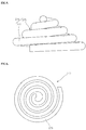
- the pipe body 273 of the air injection pipe 270 may be wound in a spiral shape.
- the pipe body 273 may have a conical shape, for example, a conical spiral shape, in which a distal end 277 of the pipe body 273 opposite to an inlet of the air injection pipe to which air is injected is disposed at the center of the spiral shape and has a higher height than other portions thereof.
- Figure 3 is a perspective view of one example of the air injection pipe 270, the pipe body 273 of which is wound in a spiral shape
- Figure 4 is a top view of one example of the air injection pipe
- Figure 5 is a side view of one example of the air injection pipe
- Figure 6 is a bottom view of one example of the air injection pipe.
- Figure 3 to Figure 6 show the air injection pipe 270 wound in a conical spiral shape.
- the singular forms “a,” “an,” and “the” may be intended to include the plural forms as well, unless context clearly indicates otherwise.
- the terms “comprises,” “comprising,” “including,” and “having,” are inclusive and therefore specify the presence of stated features, integers, steps, operations, elements, and/or components, but do not preclude the presence or addition of one or more other features, integers, steps, operations, elements, components, and/or groups thereof.
- spatially relative terms such as “upper” and “lower” are defined with reference to the accompanying drawings, and can be used interchangeably.
- the “hollow fiber membrane module” means an apparatus including a hollow fiber membrane part and an aerator, may have various shapes, and may further include additional features constituting a filtering apparatus including hollow fiber membranes.
- the hollow fiber membrane module includes a housing 100, header portions 210, 230, a hollow fiber membrane part 300, and an aerator including an air injection pipe 270 for supplying bubbles 271 for aeration.
- the hollow fiber membrane part 300 is disposed inside the housing 100 constituting an external appearance of the hollow fiber membrane module, and may include a plurality of hollow fiber membranes, which are arranged in the form of bundles.
- the hollow fiber membranes constituting the hollow fiber membrane part 300 may be formed of a material capable of filtering raw water that requires water treatment or purification.
- the hollow fiber membranes may be formed of polyolefin, polysulfone, polyethersulfone, polyimide, polyether imide, cellulose, cellulose acetate, polyvinyl alcohol, polyamide, polyethylene, polyethylene fluoride, polyvinylidene fluoride, polyacrylonitrile, polypropylene, polymethyl methacrylate, polytetrafluoroethylene, or polyether ketone.
- the header portions 210, 230 may be formed of, for example, polyvinyl chloride, polyolefin, polycarbonate, polysulfone, acrylic, acrylonitrile butadiene styrene (ABS), modified PPE (polyphenylene ether) resins, and the like.
- the air injection pipe 270 may be disposed near the lower header portion 230 such that pores 275 of the air injection pipes 270 are open towards the upper header portion 210. Bubbles 271 created by the pores 275 are moved from a lower end of the housing 100 to an upper end thereof while removing contaminants from the hollow fiber membrane part 300.
- the air injection pipe 270 may be securely fastened to the lower header portion 230 by a bonding agent or the like.
- the pipe body 273 of the air injection pipe 270 may be provided to an intermediate portion or an upper end of the housing 100 within the housing 100 in order to provide further improved aeration effects.
- the pores 275 may be formed on the pipe body to be open upwards or downwards. In a structure wherein the pipe body 273 is disposed near the upper end of the housing 100 within the housing 100, the pores 275 may be formed on the pipe body to be open towards the lower header portion 210. In some embodiments, a plurality of pipe bodies 273 may be disposed in plural layers within the housing 100 to provide further improved aeration effects.
- the pores 275 may be arranged at constant intervals in a predetermined pattern along the pipe body 273, or may be irregularly arranged along the pipe body 273.
- the pores 275 may have a size of about 2 mm to 15 mm.
- the pores 275 may be arranged substantially at constant intervals of, for example, about 20 mm to 100 mm.
- the pores 275 may be arranged on the pipe body such that a separation distance between the pores 275 gradually decreases with increasing distance from the inlet of the air injection pipe to which air is injected, that is, from an edge of the pipe body to the center thereof.
- the pores 275 may be arranged at an interval of about 60 mm to about 100 mm near the edge of the pipe body, and may be arranged at an interval of about 20 mm to about 60 mm near the center of the pipe body.
- the separation distance between the pores 275 gradually decreases and the density of the pores 275 gradually increases with decreasing distance to the center of the pipe body such that bubbles 271 can be more efficiently supplied to the center of the hollow fiber membrane part 300, thereby providing further improved aeration effects.
- the pores 275 may be separated from each other or may be gathered in groups of pores.
- the pipe body 273 of the air injection pipe 270 since the pipe body 273 of the air injection pipe 270 has a spiral shape, the entirety of a bottom of the housing 100 can be covered by a single pipe body 273. Air injected into one inlet of the pipe body 273 flows into the pores 275 formed on the pipe body 273 through the pipe body 273. Accordingly, it is sufficient for a single pipe body 273 to supply bubbles 271 to the entirety of the hollow fiber membrane part 300 disposed inside the housing 100, as shown in Figure 1 . Furthermore, the pipe body 273 wound in the spiral shape may provide a structure wherein a portion of the pipe body 273 placed at a central portion of the housing 100 is higher than other portions thereof.
- the pipe body 273 of the air injection pipe 270 may be wound in a spiral shape in which a distal end 277 of the pipe body 273 is placed at the central portion of the pipe body 273 as shown in Figure 3 , the height of the pipe body 273 gradually decreases from the central portion of the housing 100, at which the distal end 277 of the pipe body 273 is placed, to an outer circumference of the housing 100, as shown in Figure 1 and Figure 2 .
- the hollow fiber membrane module can effectively supply bubbles 271 to the hollow fiber membranes disposed at the center of the hollow fiber membrane part 100, which is disposed at the central portion of the housing 100. Accordingly, the hollow fiber membrane module can effectively remove contaminants caused by aeration operation.
- the pipe body 273 of the air injection pipe 270 is wound in a spiral shape, individual hollow fiber membranes or bundles of hollow fiber membranes may be connected to the lower header portion 210 through a space between one portion of the pipe body 273 and another portion thereof. Since the pipe body 273 may be interposed between the hollow fiber membranes, the pores 275 are also placed between the hollow fiber membranes and guide the bubbles 271 to be more effectively supplied to the individual hollow fiber membranes. With this structure, the hollow fiber membrane module can further improve aeration effects.
- hollow fiber membrane modules may collect filtered water only at one end of the hollow fiber membrane part 300, for example, by the upper header portion 210 fastened to the upper end of the housing.
- the hollow fiber membrane module may further include a circulation system for supplying, withdrawing or circulating raw water and condensate water.
- the hollow fiber membrane module may further include a drive unit such as a pump, which is connected to supply pipes, withdrawal pipes or circulation pipes.
- the hollow fiber membrane module may further include a pipe or a pump for extracting filtered water.
- the hollow fiber membrane module may be further provided at a side of the lower end of the housing 100 with a raw water supply port (not shown), and at a side of the upper end of the housing opposite to the side of the lower end with an condensate water discharge port. Since the air injection pipe 270 may be disposed inside the housing 100 regardless of a raw water supply position, formation of the raw water supply port can be achieved with high freedom of design, thereby allowing the housing 100 to have a more simple appearance.
- a spiral aerator and a hollow fiber membrane module according to the present disclosure can be applied to various types of water treatment such as water purification and treatment of industrial water, re-used water, waste water, and the like.
Landscapes
- Chemical & Material Sciences (AREA)
- Chemical Kinetics & Catalysis (AREA)
- Life Sciences & Earth Sciences (AREA)
- Hydrology & Water Resources (AREA)
- Engineering & Computer Science (AREA)
- Environmental & Geological Engineering (AREA)
- Water Supply & Treatment (AREA)
- Organic Chemistry (AREA)
- Separation Using Semi-Permeable Membranes (AREA)
Abstract
Description
- Embodiments of the present disclosure relate to a water treatment technique, and more particularly, to a spiral aerator and a hollow fiber membrane module including the same.
- A technology for selective separation of materials through membranes is used in water treatment such as water purification and treatment of industrial water, re-used water, waste water, and the like. In order to improve productivity of water purification, hollow fiber membranes are generally used as the membranes. A module or filtering apparatus using hollow fiber membranes may have a structure wherein a bundle of hollow fiber membranes is secured to a header. A hollow fiber membrane module may be operated in a dipping manner or in a compressive manner which can provide superior capabilities in treatment of produced water despite requirements for a separate system for fluid circulation.
- For filtering or purification technology using such a hollow fiber membrane module, formation of a cake layer is proposed as a main technical issue as a method for preventing or removing contamination of surfaces of hollow fiber membranes. In order to remove such contamination, there is proposed a method of separating contaminants from hollow fiber membranes by supplying air to the hollow fiber membranes. Korean Patent Laid-open Publication No.
10-2012-0007946 10-2011-0066234 10-2011-0039045 10-2010-0092227 2006-205119 - In order to achieve more efficient cleaning of hollow fiber membranes, various attempts have been made to further improve aeration effects of separating contaminants from the hollow fiber membranes by blowing air thereto.
- Embodiments of the present disclosure provide an aerator capable of more efficiently supplying air to a central portion of a hollow fiber membrane module, and a hollow fiber membrane module including the same.
- In accordance with one aspect of the present disclosure, there is provided a hollow fiber membrane module including: a housing; a hollow fiber membrane part disposed inside the housing; and an air injection pipe having a plurality of pores formed along a pipe body thereof to supply bubbles to the hollow fiber membrane part, and the pipe body is wound in a spiral shape.
- The hollow fiber membrane part may include a plurality of hollow fiber membranes, and the hollow fiber membranes may be connected to the header through a space between one portion of the pipe body wound in the spiral shape and another portion of the pipe body.
- The hollow fiber membrane module may further include a transfer pipe transferring filtered water collected by a lower header portion to an upper header portion such that the filtered water is drawn into the upper header portion.
- The air injection pipe may include the pipe body wound in the spiral shape about the transfer pipe.
- The air injection pipe may include the pipe body wound in a spiral shape in which a distal end of the pipe body is placed at a central portion of the housing inside the housing and a height of the pipe body gradually decreases from the central portion of the housing to an outer circumference thereof.
- In accordance with another aspect of the present disclosure, there is provided an aerator including an air injection pipe having a plurality of pores formed along a pipe body thereof to supply bubbles to a hollow fiber membrane part, wherein the pipe body is wound in a spiral shape. The air injection pipe may have a spiral shape in which a distal end of the pipe body of the air injection pipe is placed at a central portion of the housing inside the housing and a height of the pipe body gradually decreases from the central portion of the housing to an outer circumference thereof.
- Embodiments of the present disclosure provide an aerator capable of more efficiently supplying air to a central portion of a hollow fiber membrane module, and a hollow fiber membrane module including the same.
-
-
Figure 1 andFigure 2 are views illustrating a hollow fiber membrane module in accordance with one embodiment of the present disclosure. -
Figure 3 to Figure 6 are views of an aerator applied to a hollow fiber membrane module in accordance with one embodiment of the present disclosure. - Embodiments of the present disclosure will be described in more detail with reference to the accompanying drawings.
-
Figure 1 andFigure 2 show a hollow fiber membrane module according to one embodiment of the present disclosure. Referring toFigure 1 andFigure 2 , a hollow fiber membrane module may include ahousing 100,header portions fiber membrane part 300. The hollow fiber membrane module may be provided with an aerator, which includes anair injection pipe 270 to supplybubbles 271 for aeration to the hollowfiber membrane part 300. - The
housing 100 constitutes an external appearance of the hollow fiber membrane module and the hollowfiber membrane part 300 is disposed inside thehousing 100 and may include a plurality of hollow fiber membranes, which are arranged in the form of bundles. One or both ends of the hollowfiber membrane part 300 may be secured to theheader portions upper header portion 210 and alower header portion 230 may be fastened to thehousing 100 and secure upper and lower ends of the hollowfiber membrane part 300, respectively. The hollowfiber membrane part 300 is disposed inside thehousing 100 to which theupper header portion 210 and thelower header portion 230 are fastened, and raw water to be treated may be supplied to thehousing 100. The raw water may be purified by the hollow fiber membranes constituting the hollowfiber membrane part 300. Filtered water or purified water having passed through the hollowfiber membrane part 300 may be collected by theupper header portion 210 or thelower header portion 230 connected to the hollowfiber membrane part 300. The upper andlower header portions upper header portion 210 and thelower header portion 230 may include a water passage through which water can flow. Theupper header portion 210 and thelower header portion 230 may be formed of any material so long as the material has a certain level of mechanical strength and durability. - The filtered water collected by the
lower header portion 230 is transferred to theupper header portion 210 through atransfer pipe 250, which may be disposed inside thehousing 100 and connect theupper header portion 210 to thelower header portion 230, as shown inFigure 2 . Thetransfer pipe 250 may be disposed at an inner center of thehousing 100. With the structure wherein thetransfer pipe 250 is disposed inside thehousing 100, the hollow fiber membrane module according to the embodiment does not require installation of a separate water transfer pipe outside thehousing 100 to transfer the filtered water from thelower header portion 230 to theupper header portion 210. With this structure, the external appearance of thehousing 100 can be more simply designed, thereby enabling elimination of a complicated pipe in installation of the hollow fiber membrane module or installation of a purifying or filtering system including the hollow fiber membrane module. Since the hollow fiber membrane module according to this embodiment can collect filtered water at both ends of the hollowfiber membrane part 300, it is possible to achieve effective increase in productivity of filtered water. - Referring again to
Figure 1 , in order to remove contaminants from the hollowfiber membrane part 300, the hollow fiber membrane module according to this embodiment may include theair injection pipe 270 constituting an aerator inside thehousing 100. The aerator including theair injection pipe 270 serves to provide aeration effects of separating contaminants from the hollowfiber membrane part 300 by blowing air thereto.Bubbles 271 generated by air blowing may be provided to the hollowfiber membrane part 300 inside thehousing 100 throughpores 275 formed on apipe body 273 of theair injection pipe 270. Thebubbles 271 serve to perform aeration or air diffusion operation around the hollowfiber membrane part 300 such that contaminants created on the hollowfiber membrane part 300 can be separated and removed therefrom by fluid flow resulting from the aeration or air diffusion operation of the bubbles. The contaminants can be discharged from thehousing 100 together with condensate water or contaminated water, which is produced by filtration of raw water. - As shown in
Figure 3 , thepipe body 273 of theair injection pipe 270 may be wound in a spiral shape. Thepipe body 273 may have a conical shape, for example, a conical spiral shape, in which adistal end 277 of thepipe body 273 opposite to an inlet of the air injection pipe to which air is injected is disposed at the center of the spiral shape and has a higher height than other portions thereof.Figure 3 is a perspective view of one example of theair injection pipe 270, thepipe body 273 of which is wound in a spiral shape,Figure 4 is a top view of one example of the air injection pipe,Figure 5 is a side view of one example of the air injection pipe, andFigure 6 is a bottom view of one example of the air injection pipe.Figure 3 to Figure 6 show theair injection pipe 270 wound in a conical spiral shape. - Hereinafter, embodiments of the present disclosure will be described in detail with reference to the accompanying drawings. The following embodiments are provided by way of example so as to fully convey the spirit of the present disclosure to those skilled in the art to which the present disclosure pertains. Accordingly, the present disclosure is not limited to the embodiments disclosed herein and can also be implemented in different forms. In the drawings, widths, lengths, thicknesses, and the like of elements can be exaggerated for clarity and descriptive purposes. It will be understood that when an element is referred to as being "on" another element, it can be directly on the other element or intervening elements may also be present. Throughout the specification, like reference numerals denote like elements having the same or similar functions. As used herein, the singular forms "a," "an," and "the" may be intended to include the plural forms as well, unless context clearly indicates otherwise. The terms "comprises," "comprising," "including," and "having," are inclusive and therefore specify the presence of stated features, integers, steps, operations, elements, and/or components, but do not preclude the presence or addition of one or more other features, integers, steps, operations, elements, components, and/or groups thereof. As used herein, spatially relative terms such as "upper" and "lower" are defined with reference to the accompanying drawings, and can be used interchangeably. As used herein, the "hollow fiber membrane module" means an apparatus including a hollow fiber membrane part and an aerator, may have various shapes, and may further include additional features constituting a filtering apparatus including hollow fiber membranes.
- Referring again to
Figure 1 andFigure 2 , the hollow fiber membrane module includes ahousing 100,header portions fiber membrane part 300, and an aerator including anair injection pipe 270 for supplyingbubbles 271 for aeration. The hollowfiber membrane part 300 is disposed inside thehousing 100 constituting an external appearance of the hollow fiber membrane module, and may include a plurality of hollow fiber membranes, which are arranged in the form of bundles. - The hollow fiber membranes constituting the hollow
fiber membrane part 300 may be formed of a material capable of filtering raw water that requires water treatment or purification. The hollow fiber membranes may be formed of polyolefin, polysulfone, polyethersulfone, polyimide, polyether imide, cellulose, cellulose acetate, polyvinyl alcohol, polyamide, polyethylene, polyethylene fluoride, polyvinylidene fluoride, polyacrylonitrile, polypropylene, polymethyl methacrylate, polytetrafluoroethylene, or polyether ketone. Theheader portions upper header portion 210 and thelower header portion 230, may be formed of, for example, polyvinyl chloride, polyolefin, polycarbonate, polysulfone, acrylic, acrylonitrile butadiene styrene (ABS), modified PPE (polyphenylene ether) resins, and the like. - The
air injection pipe 270 may be disposed near thelower header portion 230 such that pores 275 of theair injection pipes 270 are open towards theupper header portion 210.Bubbles 271 created by thepores 275 are moved from a lower end of thehousing 100 to an upper end thereof while removing contaminants from the hollowfiber membrane part 300. Theair injection pipe 270 may be securely fastened to thelower header portion 230 by a bonding agent or the like. Alternatively, thepipe body 273 of theair injection pipe 270 may be provided to an intermediate portion or an upper end of thehousing 100 within thehousing 100 in order to provide further improved aeration effects. In a structure wherein thepipe body 273 is provided to the intermediate portion of thehousing 100, thepores 275 may be formed on the pipe body to be open upwards or downwards. In a structure wherein thepipe body 273 is disposed near the upper end of thehousing 100 within thehousing 100, thepores 275 may be formed on the pipe body to be open towards thelower header portion 210. In some embodiments, a plurality ofpipe bodies 273 may be disposed in plural layers within thehousing 100 to provide further improved aeration effects. - Referring again to
Figure 1 andFigure 3 , thepores 275 may be arranged at constant intervals in a predetermined pattern along thepipe body 273, or may be irregularly arranged along thepipe body 273. Thepores 275 may have a size of about 2 mm to 15 mm. In one embodiment, thepores 275 may be arranged substantially at constant intervals of, for example, about 20 mm to 100 mm. In another embodiment, thepores 275 may be arranged on the pipe body such that a separation distance between thepores 275 gradually decreases with increasing distance from the inlet of the air injection pipe to which air is injected, that is, from an edge of the pipe body to the center thereof. For example, thepores 275 may be arranged at an interval of about 60 mm to about 100 mm near the edge of the pipe body, and may be arranged at an interval of about 20 mm to about 60 mm near the center of the pipe body. The separation distance between thepores 275 gradually decreases and the density of thepores 275 gradually increases with decreasing distance to the center of the pipe body such that bubbles 271 can be more efficiently supplied to the center of the hollowfiber membrane part 300, thereby providing further improved aeration effects. - Alternatively, the
pores 275 may be separated from each other or may be gathered in groups of pores. - As shown in
Figure 2 , since thepipe body 273 of theair injection pipe 270 has a spiral shape, the entirety of a bottom of thehousing 100 can be covered by asingle pipe body 273. Air injected into one inlet of thepipe body 273 flows into thepores 275 formed on thepipe body 273 through thepipe body 273. Accordingly, it is sufficient for asingle pipe body 273 to supplybubbles 271 to the entirety of the hollowfiber membrane part 300 disposed inside thehousing 100, as shown inFigure 1 . Furthermore, thepipe body 273 wound in the spiral shape may provide a structure wherein a portion of thepipe body 273 placed at a central portion of thehousing 100 is higher than other portions thereof. Since thepipe body 273 of theair injection pipe 270 may be wound in a spiral shape in which adistal end 277 of thepipe body 273 is placed at the central portion of thepipe body 273 as shown inFigure 3 , the height of thepipe body 273 gradually decreases from the central portion of thehousing 100, at which thedistal end 277 of thepipe body 273 is placed, to an outer circumference of thehousing 100, as shown inFigure 1 andFigure 2 . With this structure, the hollow fiber membrane module can effectively supplybubbles 271 to the hollow fiber membranes disposed at the center of the hollowfiber membrane part 100, which is disposed at the central portion of thehousing 100. Accordingly, the hollow fiber membrane module can effectively remove contaminants caused by aeration operation. - Since the
pipe body 273 of theair injection pipe 270 is wound in a spiral shape, individual hollow fiber membranes or bundles of hollow fiber membranes may be connected to thelower header portion 210 through a space between one portion of thepipe body 273 and another portion thereof. Since thepipe body 273 may be interposed between the hollow fiber membranes, thepores 275 are also placed between the hollow fiber membranes and guide thebubbles 271 to be more effectively supplied to the individual hollow fiber membranes. With this structure, the hollow fiber membrane module can further improve aeration effects. - Referring again to
Figure 1 , although the hollow fiber membrane module according to this embodiment has been described as having a function of collecting filtered water at both ends of the hollowfiber membrane part 300, hollow fiber membrane modules according to other embodiments of the present invention may collect filtered water only at one end of the hollowfiber membrane part 300, for example, by theupper header portion 210 fastened to the upper end of the housing. The hollow fiber membrane module may further include a circulation system for supplying, withdrawing or circulating raw water and condensate water. For example, the hollow fiber membrane module may further include a drive unit such as a pump, which is connected to supply pipes, withdrawal pipes or circulation pipes. In addition, the hollow fiber membrane module may further include a pipe or a pump for extracting filtered water. The hollow fiber membrane module may be further provided at a side of the lower end of thehousing 100 with a raw water supply port (not shown), and at a side of the upper end of the housing opposite to the side of the lower end with an condensate water discharge port. Since theair injection pipe 270 may be disposed inside thehousing 100 regardless of a raw water supply position, formation of the raw water supply port can be achieved with high freedom of design, thereby allowing thehousing 100 to have a more simple appearance. - Although some embodiments have been described herein, it should be understood by those skilled in the art that various modifications, variations and alterations can be made without departing from the spirit and scope of the present disclosure set forth in the accompanying claims.
- A spiral aerator and a hollow fiber membrane module according to the present disclosure can be applied to various types of water treatment such as water purification and treatment of industrial water, re-used water, waste water, and the like.
Claims (14)
- A hollow fiber membrane module comprising:a housing;a hollow fiber membrane part disposed inside the housing; andan air injection pipe having a plurality of pores formed along a pipe body thereof to supply bubbles to the hollow fiber membrane part, the pipe body being wound in a spiral shape.
- The hollow fiber membrane module according to claim 1, further comprising: a header securing the hollow fiber membrane part.
- The hollow fiber membrane module according to claim 2, wherein the hollow fiber membrane part comprises a plurality of hollow fiber membranes,
the hollow fiber membranes being connected to the header through a space between one portion of the pipe body wound in the spiral shape and another portion of the pipe body. - The hollow fiber membrane module according to claim 3, wherein the header comprises an upper header portion and a lower header portion securing upper and lower ends of the hollow fiber membrane part, respectively.
- The hollow fiber membrane module according to claim 4, wherein the air injection pipe is placed near the lower header portion and the pores are open towards the upper header portion.
- The hollow fiber membrane module according to claim 4, further comprising:a transfer pipe transferring filtered water collected by the lower header portion to the upper header portion such that the filtered water is drawn into the upper header portion.
- The hollow fiber membrane module according to claim 6, wherein the transfer pipe is disposed inside the housing and connects the lower header portion and the upper header portion to each other.
- The hollow fiber membrane module according to claim 7, wherein the air injection pipe comprises the pipe body wound in the spiral shape about the transfer pipe.
- The hollow fiber membrane module according to claim 1, wherein the pores of the air injection pipe are arranged at constant intervals along the pipe body.
- The hollow fiber membrane module according to claim 1, wherein the pores of the air injection pipe are arranged at gradually decreasing intervals with increasing distance from an inlet of the air injection pipe to which air is injected.
- The hollow fiber membrane module according to claim 1, wherein the pores of the air injection pipe are irregularly arranged.
- The hollow fiber membrane module according to claim 1, wherein the air injection pipe comprises the pipe body wound in the spiral shape in which a distal end of the pipe body is placed at a central portion of the housing inside the housing and a height of the pipe body gradually decreases from the central portion of the housing to an outer circumference thereof.
- An aerator hollow comprising an air injection pipe having a plurality of pores formed along a pipe body thereof to supply bubbles to a hollow fiber membrane part, the pipe body being wound in a spiral shape.
- The aerator according to claim 13, wherein the air injection pipe has a spiral shape in which a distal end of the pipe body of the air injection pipe is placed at a central portion of the housing inside the housing and a height of the pipe body gradually decreases from the central portion of the housing to an outer circumference thereof.
Applications Claiming Priority (2)
| Application Number | Priority Date | Filing Date | Title |
|---|---|---|---|
| KR1020130103081A KR101889109B1 (en) | 2013-08-29 | 2013-08-29 | Apparatus of spiral aerator and hollow fiber membrane module including the same |
| PCT/KR2013/011190 WO2015030310A1 (en) | 2013-08-29 | 2013-12-05 | Spiral aerator and hollow fiber membrane module having same |
Publications (2)
| Publication Number | Publication Date |
|---|---|
| EP3040111A1 true EP3040111A1 (en) | 2016-07-06 |
| EP3040111A4 EP3040111A4 (en) | 2017-05-10 |
Family
ID=52586832
Family Applications (1)
| Application Number | Title | Priority Date | Filing Date |
|---|---|---|---|
| EP13892414.7A Withdrawn EP3040111A4 (en) | 2013-08-29 | 2013-12-05 | Spiral aerator and hollow fiber membrane module having same |
Country Status (5)
| Country | Link |
|---|---|
| US (1) | US20160207002A1 (en) |
| EP (1) | EP3040111A4 (en) |
| KR (1) | KR101889109B1 (en) |
| CN (1) | CN105531018A (en) |
| WO (1) | WO2015030310A1 (en) |
Families Citing this family (2)
| Publication number | Priority date | Publication date | Assignee | Title |
|---|---|---|---|---|
| CN111718044B (en) * | 2020-06-30 | 2021-01-12 | 柳州潜荣健康产业有限公司 | A pure water treatment system for gardenia jasminoides ellis extract product |
| CN120483378B (en) * | 2025-07-10 | 2025-10-28 | 蓝深集团股份有限公司 | An integrated medical wastewater treatment equipment |
Family Cites Families (25)
| Publication number | Priority date | Publication date | Assignee | Title |
|---|---|---|---|---|
| JP3080647B2 (en) * | 1990-10-09 | 2000-08-28 | エーザイ株式会社 | Cell culture device |
| US8852438B2 (en) * | 1995-08-11 | 2014-10-07 | Zenon Technology Partnership | Membrane filtration module with adjustable header spacing |
| SG54084A1 (en) * | 1995-09-14 | 1998-11-16 | Univ Singapore | Recirculating mechanical aerator |
| DE69825297T2 (en) * | 1997-04-04 | 2005-07-28 | Dickman, Daniel H., Trevor | VENT DIFFUSER |
| US6641733B2 (en) * | 1998-09-25 | 2003-11-04 | U. S. Filter Wastewater Group, Inc. | Apparatus and method for cleaning membrane filtration modules |
| TWI222895B (en) * | 1998-09-25 | 2004-11-01 | Usf Filtration & Separations | Apparatus and method for cleaning membrane filtration modules |
| KR19990045939A (en) * | 1999-02-24 | 1999-06-25 | 장문석 | Improved hollow fiber membrane module and method of treating waste water using same |
| DE19959103A1 (en) * | 1999-12-08 | 2001-06-21 | Messer Griesheim Gmbh | Process and device for treating waste water |
| JP3741253B2 (en) * | 1999-12-24 | 2006-02-01 | 富士通株式会社 | Chemical manufacturing equipment |
| US20030113908A1 (en) * | 2001-12-18 | 2003-06-19 | Hussey Leon R. | Compost tea apparatus and methods |
| KR20050056293A (en) * | 2003-12-10 | 2005-06-16 | 주식회사 코오롱 | A submerged hollow fiber membrane module |
| JP2006205119A (en) | 2005-01-31 | 2006-08-10 | Nikko Co | Method of using submerged membrane separator and submerged membrane separator |
| AU2008254000B9 (en) | 2007-05-22 | 2011-05-12 | Asahi Kasei Chemicals Corporation | Hollow fiber membrane module, process for manufacturing the same, hollow fiber membrane module assembly and method of purifying suspended water with use thereof |
| EP2226115B1 (en) * | 2007-12-14 | 2017-02-15 | Beijing Ecojoy Water Technology Co., Ltd | A hollow fiber membrane module |
| CN201226733Y (en) * | 2008-06-30 | 2009-04-29 | 仙桃市恒康科技有限公司 | Efficient energy-saving micro-pore oxygen increasing device |
| JP5235632B2 (en) | 2008-12-02 | 2013-07-10 | 三菱レイヨン株式会社 | Aeration device and method |
| CN201399324Y (en) * | 2009-01-16 | 2010-02-10 | 苏州膜华材料科技有限公司 | An integrated hollow fiber membrane module |
| KR101569529B1 (en) | 2009-02-12 | 2015-11-17 | 코오롱인더스트리 주식회사 | Hollow Fiber Membrane Module and Filtering System Comprising The Same |
| CN201618522U (en) | 2009-07-16 | 2010-11-03 | 杭州凯宏膜技术有限公司 | New Submerged Membrane Module |
| KR101100353B1 (en) | 2009-10-09 | 2011-12-30 | 유한회사 원진엔비텍 | Multi-layered diffuser |
| WO2011150210A2 (en) * | 2010-05-27 | 2011-12-01 | Hydranautics | Hollow fiber membrane module |
| WO2011150206A2 (en) * | 2010-05-27 | 2011-12-01 | Hydranautics | Hollow fiber membrane module |
| KR20120007946A (en) | 2010-07-15 | 2012-01-25 | 웅진케미칼 주식회사 | High Flow Pressurized Membrane Module Water Purifier |
| US9278317B2 (en) * | 2011-12-09 | 2016-03-08 | Lotte Chemical Corporation | Hollow fiber membrane module with miniskeins in miniheaders having a zig-zag configuration |
| KR101908704B1 (en) * | 2012-01-11 | 2018-10-16 | 주식회사 엘지화학 | Membrane Module using Hallow Fiber |
-
2013
- 2013-08-29 KR KR1020130103081A patent/KR101889109B1/en active Active
- 2013-12-05 WO PCT/KR2013/011190 patent/WO2015030310A1/en not_active Ceased
- 2013-12-05 EP EP13892414.7A patent/EP3040111A4/en not_active Withdrawn
- 2013-12-05 US US14/915,199 patent/US20160207002A1/en not_active Abandoned
- 2013-12-05 CN CN201380079260.6A patent/CN105531018A/en active Pending
Also Published As
| Publication number | Publication date |
|---|---|
| CN105531018A (en) | 2016-04-27 |
| US20160207002A1 (en) | 2016-07-21 |
| EP3040111A4 (en) | 2017-05-10 |
| KR20150025547A (en) | 2015-03-11 |
| KR101889109B1 (en) | 2018-09-20 |
| WO2015030310A1 (en) | 2015-03-05 |
Similar Documents
| Publication | Publication Date | Title |
|---|---|---|
| JP4445862B2 (en) | Hollow fiber membrane module, hollow fiber membrane module unit, membrane filtration device using the same, and operating method thereof | |
| EP0207379B1 (en) | Hollow-fiber filter module and filtration method using the same | |
| CN103442789B (en) | Filter plant and the hollow fiber membrane module for this filter plant | |
| KR20140001011U (en) | Hollow fiber membrane module and hollow fiber membrane module unit | |
| JP5359872B2 (en) | Immersion type hollow fiber membrane module | |
| KR101908704B1 (en) | Membrane Module using Hallow Fiber | |
| KR20190141629A (en) | Air diffusion header, air diffusion apparatus, membrane module unit, and water treatment method | |
| JP5326571B2 (en) | Filtration method | |
| CN103459002B (en) | Filtration membrane module and filtration system including the filtration membrane module | |
| US20160207002A1 (en) | Spiral aerator and hollow fiber membrane module having same | |
| CN103842056B (en) | Aeration unit and include its defecator | |
| KR100544383B1 (en) | Hollow Fiber Membrane Module Combined with Air Diffuser | |
| CN107531529A (en) | Membrane separation activated sludge treatment method and membrane separation activated sludge treatment system | |
| KR102625914B1 (en) | Hollow fiber membrane module for wastewater filtering apparatus using | |
| WO2011150206A2 (en) | Hollow fiber membrane module | |
| KR20160111892A (en) | Apparatus of spiral aerator and hollow fiber membrane module including the same | |
| JP2026501535A (en) | Integrated prefilter for UF/MF membrane systems | |
| KR102336809B1 (en) | Filtering apparatus of submerged type | |
| JP4488402B2 (en) | Hollow fiber membrane module | |
| KR102162074B1 (en) | Immersible tubular filtration membrane module | |
| KR200379550Y1 (en) | Module of flat membrane for immersion type | |
| KR100711834B1 (en) | Immersion membrane module | |
| JP2001321645A (en) | Filtration membrane element and method for producing permeated water | |
| KR101515685B1 (en) | Membrane module comprising section divider for reducing membrane fouling | |
| KR101974612B1 (en) | Hollow fiber membrane module of in-out mode with high washing efficiency |
Legal Events
| Date | Code | Title | Description |
|---|---|---|---|
| PUAI | Public reference made under article 153(3) epc to a published international application that has entered the european phase |
Free format text: ORIGINAL CODE: 0009012 |
|
| 17P | Request for examination filed |
Effective date: 20160303 |
|
| AK | Designated contracting states |
Kind code of ref document: A1 Designated state(s): AL AT BE BG CH CY CZ DE DK EE ES FI FR GB GR HR HU IE IS IT LI LT LU LV MC MK MT NL NO PL PT RO RS SE SI SK SM TR |
|
| AX | Request for extension of the european patent |
Extension state: BA ME |
|
| DAX | Request for extension of the european patent (deleted) | ||
| RAP1 | Party data changed (applicant data changed or rights of an application transferred) |
Owner name: LOTTE ADVANCED MATERIALS CO., LTD. Owner name: LOTTE CHEMICAL CORPORATION |
|
| A4 | Supplementary search report drawn up and despatched |
Effective date: 20170412 |
|
| RIC1 | Information provided on ipc code assigned before grant |
Ipc: B01D 65/08 20060101ALI20170403BHEP Ipc: B01D 63/02 20060101AFI20170403BHEP Ipc: B01D 65/00 20060101ALI20170403BHEP Ipc: C02F 1/44 20060101ALI20170403BHEP Ipc: B01F 3/04 20060101ALI20170403BHEP Ipc: C02F 3/20 20060101ALI20170403BHEP Ipc: B01D 65/02 20060101ALI20170403BHEP |
|
| RAP1 | Party data changed (applicant data changed or rights of an application transferred) |
Owner name: LOTTE ADVANCED MATERIALS CO., LTD. Owner name: LOTTE CHEMICAL CORPORATION |
|
| STAA | Information on the status of an ep patent application or granted ep patent |
Free format text: STATUS: REQUEST FOR EXAMINATION WAS MADE |
|
| STAA | Information on the status of an ep patent application or granted ep patent |
Free format text: STATUS: THE APPLICATION IS DEEMED TO BE WITHDRAWN |
|
| RAP1 | Party data changed (applicant data changed or rights of an application transferred) |
Owner name: LOTTE ADVANCED MATERIALS CO., LTD. Owner name: LOTTE CHEMICAL CORPORATION |
|
| 18D | Application deemed to be withdrawn |
Effective date: 20171114 |