EP3040049A1 - Opening measurement instrument - Google Patents
Opening measurement instrument Download PDFInfo
- Publication number
- EP3040049A1 EP3040049A1 EP14840885.9A EP14840885A EP3040049A1 EP 3040049 A1 EP3040049 A1 EP 3040049A1 EP 14840885 A EP14840885 A EP 14840885A EP 3040049 A1 EP3040049 A1 EP 3040049A1
- Authority
- EP
- European Patent Office
- Prior art keywords
- mouth
- opening
- measuring
- engagement part
- measuring instrument
- Prior art date
- Legal status (The legal status is an assumption and is not a legal conclusion. Google has not performed a legal analysis and makes no representation as to the accuracy of the status listed.)
- Granted
Links
- 238000005259 measurement Methods 0.000 title abstract description 54
- 210000004283 incisor Anatomy 0.000 description 27
- 238000006073 displacement reaction Methods 0.000 description 15
- 238000012360 testing method Methods 0.000 description 10
- 208000028911 Temporomandibular Joint disease Diseases 0.000 description 7
- 230000000694 effects Effects 0.000 description 5
- 230000033001 locomotion Effects 0.000 description 5
- 230000002093 peripheral effect Effects 0.000 description 5
- 210000001738 temporomandibular joint Anatomy 0.000 description 3
- 238000012549 training Methods 0.000 description 3
- 238000013459 approach Methods 0.000 description 2
- 210000002455 dental arch Anatomy 0.000 description 2
- 238000013461 design Methods 0.000 description 2
- 210000001847 jaw Anatomy 0.000 description 2
- 238000000034 method Methods 0.000 description 2
- 206010044684 Trismus Diseases 0.000 description 1
- 238000011161 development Methods 0.000 description 1
- 238000003745 diagnosis Methods 0.000 description 1
- 239000000463 material Substances 0.000 description 1
- 239000007769 metal material Substances 0.000 description 1
- 208000024891 symptom Diseases 0.000 description 1
- 229920003002 synthetic resin Polymers 0.000 description 1
- 239000000057 synthetic resin Substances 0.000 description 1
Images




Classifications
-
- G—PHYSICS
- G01—MEASURING; TESTING
- G01B—MEASURING LENGTH, THICKNESS OR SIMILAR LINEAR DIMENSIONS; MEASURING ANGLES; MEASURING AREAS; MEASURING IRREGULARITIES OF SURFACES OR CONTOURS
- G01B3/00—Measuring instruments characterised by the use of mechanical techniques
- G01B3/02—Rulers with scales or marks for direct reading
- G01B3/04—Rulers with scales or marks for direct reading rigid
-
- A—HUMAN NECESSITIES
- A61—MEDICAL OR VETERINARY SCIENCE; HYGIENE
- A61B—DIAGNOSIS; SURGERY; IDENTIFICATION
- A61B5/00—Measuring for diagnostic purposes; Identification of persons
- A61B5/103—Measuring devices for testing the shape, pattern, colour, size or movement of the body or parts thereof, for diagnostic purposes
- A61B5/107—Measuring physical dimensions, e.g. size of the entire body or parts thereof
- A61B5/1071—Measuring physical dimensions, e.g. size of the entire body or parts thereof measuring angles, e.g. using goniometers
-
- A—HUMAN NECESSITIES
- A61—MEDICAL OR VETERINARY SCIENCE; HYGIENE
- A61C—DENTISTRY; APPARATUS OR METHODS FOR ORAL OR DENTAL HYGIENE
- A61C19/00—Dental auxiliary appliances
- A61C19/04—Measuring instruments specially adapted for dentistry
- A61C19/045—Measuring instruments specially adapted for dentistry for recording mandibular movement, e.g. face bows
-
- G—PHYSICS
- G01—MEASURING; TESTING
- G01B—MEASURING LENGTH, THICKNESS OR SIMILAR LINEAR DIMENSIONS; MEASURING ANGLES; MEASURING AREAS; MEASURING IRREGULARITIES OF SURFACES OR CONTOURS
- G01B3/00—Measuring instruments characterised by the use of mechanical techniques
- G01B3/46—Plug gauges for internal dimensions with engaging surfaces which are at a fixed distance, although they may be preadjustable
- G01B3/50—Plug gauges for internal dimensions with engaging surfaces which are at a fixed distance, although they may be preadjustable of limit-gauge type, i.e. "go/no-go"
Definitions
- the present invention relates to a mouth-opening measuring instrument.
- Temporomandibular disorder is developed in a wide age range from children to adults. At present, the development of temporomandibular disorder is increasing rapidly particularly in young adults.
- One of main symptoms of temporomandibular disorder is lockjaw.
- a method of a remedy to temporomandibular disorder employs a mouth-opening training instrument disclosed for example in patent document 1. This mouth-opening training instrument is used in rehabilitation for recovering a mouth-opening function.
- Test items adopted for a remedy to temporomandibular disorder include measurement of a mouth-opening amount. Specifically, the remedy using the mouth-opening training instrument and measurement of a mouth-opening amount are applied together. Meanwhile, measurement of a mouth-opening amount is an essential test item to be adopted not only in the remedy to temporomandibular disorder but also in general dental diagnosis and treatment. Thus, a mouth-opening amount is required to be measured simply and reliably.
- a mouth-opening measuring instrument used conventionally for measuring a mouth-opening amount has a shape like a set square having scale marks given along each of two sides of the set square.
- a design for a dental ruler used for measuring the amount of mouth-opening between an upper row of teeth and a lower row of teeth is also known (patent document 2).
- the present invention has been made in view of the aforementioned circumstances. It is an object of the present invention to provide a mouth-opening measuring instrument achieving excellent stability of the instrument during measurement, excellent measurement accuracy, and excellent measurement reproducibility.
- a mouth-opening amount can be measured properly by defining a tooth to be used as a reference for the measurement, providing a place where this tooth is to be fixed in a mouth-opening measuring instrument, and using this tooth as a fulcrum point during the measurement, thereby completing the present invention. More specifically, the present invention provides the following.
- the present invention achieves excellent stability of the instrument during measurement, excellent measurement accuracy, and excellent measurement reproducibility.
- a mouth-opening measuring instrument 10 of a first embodiment is used for measuring the amount of mouth-opening between an upper jaw and a lower jaw. More specifically, the mouth-opening measuring instrument 10 is used for measuring a distance between front teeth in the lower jaw (first reference teeth 21 described later) and front teeth in the upper jaw (second reference teeth 31 described later) as a mouth-opening amount (see FIG. 5 ).
- the mouth-opening measuring instrument 10 has a columnar shape in a form like a sector in cross section.
- the mouth-opening measuring instrument 10 of the first embodiment includes an engagement part 11, a measuring surface 12, first scale marks 13, second scale marks 14, a reference line 16, and gripping surfaces 15 in a pair.
- the engagement part 11 is provided at one end portion of a curved part of the mouth-opening measuring instrument 10 in a peripheral direction LD. As shown in FIGS. 1 to 3 , the engagement part 11 includes a first reference tooth abutting surface 111 and recessed surfaces 112.
- the first reference tooth abutting surface 111 is disposed in the center of the engagement part 11 in a width direction WD.
- the recessed surfaces 112 are disposed on opposite sides of the first reference tooth abutting surface 111 in the width direction WD.
- the recessed surfaces 112 are recessed compared to the first reference tooth abutting surface 111.
- the measuring surface 12 is provided in the curved part of the mouth-opening measuring instrument 10.
- the measuring surface 12 includes a curved surface along which the measuring surface 12 between the engagement part 11 and a predetermined place 121 on a measuring surface (a position on the measuring surface 12 separated from the engagement part 11) bulges out from a plane F connecting the engagement part 11 and the predetermined place 121 on a measuring surface.
- FIG. 2 shows only one predetermined place 121 on a measuring surface
- the predetermined place 121 referred to in the first embodiment includes every place on the measuring surface 12 on which the second reference teeth 31 described later are to abut during measurement.
- the measuring surface 12 includes a curved surface increased in curvature with a greater distance from the engagement part 11.
- the first scale marks 13 are given on the measuring surface 12.
- the first scale marks 13 start from the engagement part 11, are separated at predetermined intervals along the measuring surface 12 in the peripheral direction LD, and extend in the width direction WD.
- the first scale marks 13 indicate a distance from the engagement part 11.
- the distance from the engagement part 11 mentioned herein means a linear distance from the engagement part 11 (first reference tooth abutting surface 111) to a point where the first scale mark 13 is given. This distance is a distance on the plane F shown in FIG. 2 .
- the first scale marks 13 are given at intervals of 10 mm in a range where a distance from the engagement part 11 does not exceed 30 mm and at intervals of 5 mm in a range where this distance exceeds 30 mm.
- the second scale marks 14 are given at intervals of 1 mm in the width direction WD perpendicular to the peripheral direction LD of the measuring surface 12.
- the second scale marks 14 indicate a position in a direction perpendicular to a direction where the first scale marks 13 are given.
- the second scale marks 14 are given for a corresponding one of the first scale marks 13.
- the reference line 16 is disposed in the center of the measuring surface 12 in the width direction WD and extends in the peripheral direction LD of the measuring surface 12.
- the reference line 16 functions as a reference position when a mouth-opening amount is measured using the mouth-opening measuring instrument 10.
- the gripping surfaces 15 in a pair are disposed in such a manner as to hold the measuring surface 12 therebetween.
- the gripping surfaces 15 each have a form like a sector in the width direction WD of the measuring surface 12.
- the gripping surfaces 15 each include a wide surface part 152, a narrow surface part 151, and a connecting surface part 153.
- the wide surface part 152 is provided to extend continuously with the measuring surface 12 and is disposed perpendicular to the measuring surface 12. Specifically, a distance (width) between the wide surface parts 152 in a pair is equal to the length of the measuring surface 12 in the width direction WD.
- the narrow surface part 151 is disposed adjacent to the central angle of the sector form of the gripping surface 15.
- the narrow surface parts 151 in a pair are disposed at a distance (separated by a width) shorter than the distance (width) between the wide surface parts 152 in a pair.
- the connecting surface part 153 connects the wide surface part 152 and the narrow surface part 151.
- the connecting surface part 153 extends perpendicular to the wide surface part 152 and the narrow surface part 151.
- a method of using the mouth-opening measuring instrument 10 according to the first embodiment is descried next.
- a test subject is made to open his or her mouth as shown in FIG. 4 .
- the engagement part 11 of the mouth-opening measuring instrument 10 (more specifically, the first reference tooth abutting surface 111 formed by cutting as shown in FIGS. 2 and 3 )is engaged with the first reference teeth 21 in the lower jaw 20.
- the measuring surface 12 is brought into abutting contact with the second reference teeth 31 in the upper jaw 30.
- the recessed surfaces 112 positioned on opposite sides of the first reference tooth abutting surface 111 are recessed compared to the first reference tooth abutting surface 111. This makes it unlikely that the mandibular incisors 22 will abut on the recessed surfaces 112 on opposite sides of the first reference tooth abutting surface 111 when the second reference teeth 31 approach the measuring surface 12. In this way, the first reference teeth 21 can be engaged stably with the first reference tooth abutting surface 111.
- the first reference teeth 21 are mandibular central incisors in the lower jaw 20.
- the second reference teeth 31 are maxillary central incisors in the upper jaw 30.
- FIG. 6 shows a result of this measurement to the effect that lateral displacement of the mandibular incisors is not observed while the mouth is opened.
- FIG. 7 shows a result of this measurement to the effect that lateral displacement of the mandibular incisors is observed while the mouth is opened.
- the test subject is made to open his or her mouth gradually to continuously measure a place on the measuring surface 12 on which the second reference teeth 31 is abut based on the second scale marks 14. This makes it possible to record lateral displacement of the mandibular incisors continuously in response to a mouth-opening amount while the mouth is being opened, so that motions being made while the mouth is being opened can be understood.
- the aforementioned mouth-opening measuring instrument 10 of the first embodiment achieves the following effects.
- the mouth-opening measuring instrument 10 includes the engagement part 11 to be engaged with the first reference teeth 21 in a lower jaw, the measuring surface 12 on which the second reference teeth 31 in an upper jaw are to abut while the engagement part 11 is engaged with the first reference teeth 21, and the first scale marks 13 given on the measuring surface 12 and indicating a distance from the engagement part 11.
- This makes it possible to support the second reference teeth 31 in the upper jaw stably on the measuring surface 12, so that the position of the second reference teeth 31 on the measuring surface 12 can be read accurately.
- a mouth-opening amount can be measured with a high degree of accuracy. This further achieves excellent stability during measurement and measurement accuracy, thereby achieving a high degree of reproducibility.
- a mouth-opening measuring instrument conventionally used is dedicated to the function of measuring a distance between a maxillary incisor and a mandibular incisor and does not have the function of measuring the lateral displacement of the mouth-opening path properly in response to a mouth-opening amount to be caused by a discrepancy in mobility between the right and left temporomandibular joints.
- the mouth-opening measuring instrument 10 includes the second scale marks 14 given on the measuring surface 12 and indicating a position in a direction perpendicular to a direction where the first scale marks 13 are given. This makes it possible to measure lateral displacement of mandibular incisors occurring while a mouth is opened as a discrepancy between the midline of maxillary incisors and the midline of the mandibular incisors. This further makes it possible to record lateral displacement of the mandibular incisors continuously in response to a mouth-opening amount while the mouth is being opened, so that motions being made while the mouth is being opened can be understood.
- the measuring surface 12 of the mouth-opening measuring instrument 10 is a plane, the lips of a test subject are obliged to touch the mouth-opening measuring instrument 10 to make it difficult to make the measurement.
- the measuring surface 12 of the mouth-opening measuring instrument 10 includes a curved surface along which the measuring surface between the engagement part 11 and the predetermined place 121 on a measuring surface bulges out from the plane F connecting the engagement part 11 and the predetermined place 121 on a measuring surface. This avoids touching of the lips of the test subject with the mouth-opening measuring instrument 10 during measurement, so that the measurement can be made easily.
- the measuring surface 12 of the mouth-opening measuring instrument 10 is flat, during measurement of lateral displacement of mandibular incisors while a mouth is opened, the measuring surface 12 is obliged to point in a direction opposite a measuring person as a mouth-opening amount increases. This makes it hard for the measuring person to recognize the second scale marks 14 visually.
- the curved surface of the measuring surface 12 is formed to be increased in curvature with a greater distance from the engagement part 11.
- the engagement part 11 includes the first reference tooth abutting surface 111 on which the first reference teeth 21 are to abut and the recessed surfaces 112 provided on opposite sides of the first reference tooth abutting surface 111 and recessed compared to the first reference tooth abutting surface 111. This can make it unlikely that the mandibular incisors 22 positioned on opposite sides of the first reference teeth 21 will contact the recessed surfaces 112 on opposite sides of the first reference tooth abutting surface 111 when the first reference teeth 21 are brought into abutting contact with the first reference tooth abutting surface 111. In this way, the first reference teeth 21 can be aligned correctly with the engagement part 11, so that a mouth-opening amount can be measured more accurately.
- the mouth-opening measuring instrument 10 includes the gripping surfaces 15 in a pair disposed in such a manner as to hold the measuring surface 12 therebetween.
- the gripping surfaces 15 in a pair include the respective narrow surface parts 151 separated by a width narrower than the width of the measuring surface 12 in a direction where the second scale marks 14 are given. This allows a measuring person gripping the narrow surface parts 151 with his or her hand to hold the mouth-opening measuring instrument 10 easily, so that the measuring person can make measurement easily.
- a mouth-opening measuring instrument 10A of a second embodiment differing from that of the first embodiment is described below. Points common to the first and second embodiments will not be described.
- the mouth-opening measuring instrument 10A includes a first horizontal surface 17, third scale marks 171, a flange part 18, and a cutout part 19 in addition to the aforementioned structures of the first embodiment.
- the first horizontal surface 17 is provided on a surface on which the first reference teeth 21 are to abut during measurement of a forward glide amount FD described later.
- the first horizontal surface 17 is formed of a horizontal surface.
- the third scale marks 171 are given on the first horizontal surface 17.
- the third scale marks 171 indicate the forward glide amount FD. More specifically, in the second embodiment, the third scale marks 171 indicate a distance from the tip of the flange part 18, as shown in FIG. 8 .
- the forward glide amount FD shows a distance of the first reference teeth 21 from the second reference teeth 31.
- the forward glide amount FD corresponds to a distance of forward glide resulting from forward gliding motion of the lower jaw 20 of moving back and forth relative to the upper jaw 30.
- the third scale marks 171 are given at intervals of 1 mm.
- the forward glide amount FD is obtained as follows. As shown in FIG. 9 , the second reference teeth 31 are placed on the flange part 18 described later. The first reference teeth 21 are brought into abutting contact with the first horizontal surface 17 in a state before the lower jaw 20 starts gliding. Then, the lower jaw 20 in abutting contact is caused to glide forward to measure a position on the first horizontal surface 17 of the first reference teeth 21 abut on after the glide. Next, a difference between the placement position of the second reference teeth 31 and the abutting position of the first reference teeth 21 is read, thereby obtaining the forward glide amount FD.
- the state of the lower jaw 20 before the glide is indicated by dotted lines of FIG. 9 and the state of the lower jaw 20 after the glide is indicated by solid lines of FIG. 9 .
- the flange part 18 of the mouth-opening measuring instrument 10A is provided in a part where the second reference teeth 31 are to be placed during measurement of the forward glide amount FD.
- the flange part 18 projects from the first horizontal surface 17 in a direction toward the part where the second reference teeth 31 are to be placed.
- the flange part 18 projects 5 mm.
- the flange part 18 is formed into a projecting shape in the mouth-opening measuring instrument 10A. This allows the second reference teeth 31 to be placed stably on the flange part 18 during measurement of the forward glide amount FD.
- the third scale marks 171 reach the tip of the flange part 18. Meanwhile, in FIG. 9 the illustration of the third scale marks 171 is omitted from the flange part 18.
- the cutout part 19 is disposed between the measuring surface 12 and the first horizontal surface 17. As shown in FIG. 9 , the cutout part 19 has a shape recessed compared to the measuring surface 12 in order to prevent the upper lip of a test subject from touching the measuring surface 12 of the mouth-opening measuring instrument 10A and the second reference teeth 31 placed on the flange part 18 are housed in the cutout part 19 during measurement of the forward glide amount FD.
- the aforementioned mouth-opening measuring instrument 10A of the second embodiment achieves the following effects.
- the mouth-opening measuring instrument 10A includes the third scale marks 171 indicating the forward glide amount FD of the first reference teeth 21 relative to the second reference teeth 31. This makes it possible to measure the degree of forward gliding motion of the lower jaw 20 of moving back and forth relative to the upper jaw 30.
- the value of the forward glide amount FD and the value of the aforementioned mouth-opening amount can be used in combination for a test to be conducted for a remedy to temporomandibular disorder.
- the mouth-opening measuring instrument 10A further includes the cutout part 19 having a shape recessed compared to the measuring surface 12.
- the flange part 18 is caught between the first reference teeth 21 and the second reference teeth 31, so that the mouth-opening measuring instrument 10A does not move up and down during measurement. This facilitates measurement, so that the measurement can be made with a high degree of accuracy.
- the forward glide amount FD can also be obtained by bringing the second reference teeth 31 into abutting contact with the tip of the flange part 18 and making the first reference teeth 21 glide forward. In this case, a position on the first horizontal surface 17 on which the first reference teeth 21 abut after the glide is measured and this measured position can be used as it is as the forward glide amount FD.
- the present invention is not limited to the preferred embodiments of the mouth-opening measuring instrument according to the present invention but can be changed, where appropriate.
- mandibular central incisors are used as the first reference teeth and maxillary central incisors are used as the second reference teeth.
- the maxillary central incisors may be used as the first reference teeth and the mandibular central incisors may be used as the second reference teeth.
- a position on the measuring surface 12 on which the second reference teeth 31 is abut can be measured based on the first scale marks or the second scale marks. In this way, a mouth-opening amount and lateral displacement of the mandibular incisors can be measured while a mouth is opened.
- a lower jaw in an occlusal position may be displaced laterally.
- the mouth-opening measuring instrument of the present invention still allows measurement of the lateral displacement occurring while a mouth is opened, specifically, the amount of lateral displacement of a mouth-opening path for the lower jaw using the position of the lower jaw displaced laterally as a reference.
- the measuring surface 12 is configured in such a manner that the predetermined place 121 on a measuring surface includes every place on the measuring surface 12 on which the second reference teeth 31 are to abut during measurement.
- the measuring surface 12 may also be configured in such a manner that the predetermined place 121 on a measuring surface includes one place on the measuring surface 12 on which the second reference teeth 31 are to abut during measurement.
- the curved surface of the measuring surface 12 is formed to be increased in curvature with a greater distance from the engagement part 11.
- the curved surface of the measuring surface 12 may also be configured in such a manner that the curvature is increased in a part of the curved surface with a greater distance from the engagement part 11 while not being increased over the curved surface entirely with a greater distance from the engagement part 11.
- the recessed surfaces 112 are positioned on opposite sides of the first reference tooth abutting surface 111 and recessed compared to the first reference tooth abutting surface 111.
- the recessed surface 112 may also be configured in such a manner as to be positioned on at least one side of the first reference tooth abutting surface 111 and recessed compared to the first reference tooth abutting surface 111.
- a material used in the first and second embodiments is not particularly limited.
- various synthetic resins or metal materials can be used.
- the first scale marks 13 are given at intervals of 10 mm or 5 mm. However, this is not the only case. Specifically, the first scale marks 13 can be given at intervals such as 1 mm or 2 mm that are determined appropriately depending on purpose. For example, all the first scale marks 13 can be given at intervals of 1 mm and scale marks at intervals of 1 mm can also be given on the reference line 16. Then, numerical values in units of 5 mm can be assigned both to the scale marks 13 and the scale marks on the reference line 16.
- the width of the second scale marks and the intervals of the second scale marks are also not limited but they can be determined appropriately depending on purpose.
- the third scale marks 171 are given on the first horizontal surface 17.
- the mouth-opening measuring instrument includes a surface on which the first reference teeth 21 can abut while the second reference teeth 31 abut on the mouth-opening measuring instrument, the surface on which the first reference teeth 21 can abut is a horizontal surface, and the lower jaw 20 can glide forward with the first reference teeth 21 abutting on this surface on which the first reference teeth 21 can abut.
- the third scale marks 171 may be given on a second horizontal surface 113 of the wide surface part 152 disposed adjacent to the engagement part 11 and formed of a horizontal surface shown in FIG. 8 .
- the third scale marks 171 may be given on the horizontal part of the measuring surface 12.
- the forward glide amount FD can be measured by making the lower jaw 20 glide forward while bringing the second reference teeth 31 into abutting contact with a part of the second horizontal surface 113 adjacent to the engagement part 11 or with one end of the horizontal part of the measuring surface 12 and bringing the first reference teeth 21 into abutting contact with the horizontal part of the measuring surface 12 or the second horizontal surface 113.
- the third scale marks 171 are given on the second horizontal surface 113 or the horizontal part of the measuring surface 12, the third scale marks 171 are provided in such a manner as to indicate a distance from a position on the second horizontal surface 113 or the horizontal part of the measuring surface 12 on which the second reference teeth 31 are to abut.
- the third scale marks 171 are given at intervals of 1 mm.
- these intervals are not particularly limited but can be set appropriately depending on purpose.
- the flange part 18 is configured to project 5 mm.
- the projection is not particularly limited.
- the flange part 18 may also be configured to project in a range from 1 to 10 mm, for example.
- the flange part 18 may also be configured not to project.
- the flange part 18 may have additional scale marks similar to the second scale marks 14 given on a horizontal surface to touch the incisal edge of an incisor in the upper jaw 30. In doing this, deflection to the right and left (lateral displacement amount) occurring during forward glide can also be measured.
Landscapes
- Health & Medical Sciences (AREA)
- Life Sciences & Earth Sciences (AREA)
- Oral & Maxillofacial Surgery (AREA)
- Physics & Mathematics (AREA)
- Public Health (AREA)
- Biophysics (AREA)
- Dentistry (AREA)
- General Physics & Mathematics (AREA)
- Animal Behavior & Ethology (AREA)
- General Health & Medical Sciences (AREA)
- Biomedical Technology (AREA)
- Veterinary Medicine (AREA)
- Engineering & Computer Science (AREA)
- Pathology (AREA)
- Heart & Thoracic Surgery (AREA)
- Medical Informatics (AREA)
- Molecular Biology (AREA)
- Surgery (AREA)
- Epidemiology (AREA)
- Dental Tools And Instruments Or Auxiliary Dental Instruments (AREA)
- Measurement Of The Respiration, Hearing Ability, Form, And Blood Characteristics Of Living Organisms (AREA)
Abstract
Description
- The present invention relates to a mouth-opening measuring instrument.
- Temporomandibular disorder is developed in a wide age range from children to adults. At present, the development of temporomandibular disorder is increasing rapidly particularly in young adults. One of main symptoms of temporomandibular disorder is lockjaw. Thus, a method of a remedy to temporomandibular disorder employs a mouth-opening training instrument disclosed for example in patent document 1. This mouth-opening training instrument is used in rehabilitation for recovering a mouth-opening function.
- Test items adopted for a remedy to temporomandibular disorder include measurement of a mouth-opening amount. Specifically, the remedy using the mouth-opening training instrument and measurement of a mouth-opening amount are applied together. Meanwhile, measurement of a mouth-opening amount is an essential test item to be adopted not only in the remedy to temporomandibular disorder but also in general dental diagnosis and treatment. Thus, a mouth-opening amount is required to be measured simply and reliably.
- A mouth-opening measuring instrument used conventionally for measuring a mouth-opening amount has a shape like a set square having scale marks given along each of two sides of the set square. A design for a dental ruler used for measuring the amount of mouth-opening between an upper row of teeth and a lower row of teeth is also known (patent document 2).
- Patent Document 1: Japanese Patent No.
5004291 - Patent Document 2: Design Registration No.
1369820 - However, clear directions of use of the aforementioned mouth-opening measuring instrument are not given. For example, a criterion as to which part is to touch the instrument and which distance is to be measured is not established clearly. Regarding the aforementioned dental ruler, this ruler is to be used by inserting the ruler to the inner part of a dental arch width or applying the ruler to the outer part of the dental arch width and reading scale marks on the ruler. However, a criterion for measurement is also not established for this ruler. For these reasons, the aforementioned mouth-opening measuring instrument and the aforementioned dental ruler cannot be considered as being usable for fixed and stable measurement, so that they cannot be used stably during measurement. This reduces measurement accuracy and measurement reproducibility.
- The present invention has been made in view of the aforementioned circumstances. It is an object of the present invention to provide a mouth-opening measuring instrument achieving excellent stability of the instrument during measurement, excellent measurement accuracy, and excellent measurement reproducibility.
- Regarding measurement of a mouth-opening amount, the present inventor found that a mouth-opening amount can be measured properly by defining a tooth to be used as a reference for the measurement, providing a place where this tooth is to be fixed in a mouth-opening measuring instrument, and using this tooth as a fulcrum point during the measurement, thereby completing the present invention. More specifically, the present invention provides the following.
- (1) A mouth-opening measuring instrument used for measuring the amount of mouth-opening between an upper jaw and a lower jaw, comprising: an engagement part to be engaged with a first reference tooth in one of the jaws; a measuring surface on which a second reference tooth in the other of the jaws is to abut while the engagement part is engaged with the first reference tooth; and first scale marks given on the measuring surface and indicating a distance from the engagement part.
- (2) The mouth-opening measuring instrument according to (1), further comprising second scale marks given on the measuring surface and indicating a position in a direction perpendicular to a direction where the first scale marks are given.
- (3) The mouth-opening measuring instrument according to (1) or (2), further comprising third scale marks indicating a forward glide amount of the first reference tooth relative to the second reference tooth.
- (4) The mouth-opening measuring instrument according to any one of (1) to (3), wherein the measuring surface includes a curved surface along which the measuring surface between the engagement part and a position on the measuring surface separated from the engagement part bulges out from a plane connecting the engagement part and the position on the measuring surface.
- (5) The mouth-opening measuring instrument according to (4), wherein the curved surface has a part increased in curvature with a greater distance from the engagement part.
- (6) The mouth-opening measuring instrument according to any one of (1) to (5), wherein the engagement part comprises: a first reference tooth abutting surface on which the first reference tooth is to abut; and a recessed surface provided on at least one side of the first reference tooth abutting surface and recessed compared to the first reference tooth abutting surface.
- (7) The mouth-opening measuring instrument according to any one of (1) to (6), further comprising gripping surfaces in a pair disposed in such a manner as to hold the measuring surface therebetween, wherein the griping surfaces in a pair include respective narrow surface parts separated by a width narrower than the width of the measuring surface in a direction where the second scale marks are given.
- The present invention achieves excellent stability of the instrument during measurement, excellent measurement accuracy, and excellent measurement reproducibility.
-
-
FIG. 1 is a perspective view showing a mouth-opening measuring instrument according to a first embodiment of the present invention. -
FIG. 2 is a side view showing the mouth-opening measuring instrument according to the first embodiment of the present invention. -
FIG. 3 is a front view showing the mouth-opening measuring instrument according to the first embodiment of the present invention. -
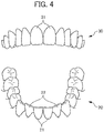
FIG. 4 shows a state where an upper jaw and a lower jaw are separated. -
FIG. 5 shows a state where a mouth-opening measuringinstrument 10 of the first embodiment is used while an engagement part of the mouth-opening measuring instrument 10 engages with the first reference teeth ofFIG. 4 and the second reference teeth ofFIG. 4 abuts on a measuring surface of the mouth-openingmeasuring instrument 10. -
FIG. 6 shows a state where the mouth-opening measuringinstrument 10 of the first embodiment is used while the engagement part of the mouth-opening measuring instrument 10 engages with the first reference teeth ofFIG. 4 and the second reference teeth ofFIG. 4 abuts on the measuring surface of the mouth-opening measuringinstrument 10 while showing the absence of lateral displacement of a lower jaw. -
FIG. 7 shows a state where the mouth-opening measuringinstrument 10 of the first embodiment is used while the engagement part of the mouth-opening measuring instrument 10 engages with the first reference teeth ofFIG. 4 and the second reference teeth ofFIG. 4 abuts on the measuring surface of the mouth-opening measuringinstrument 10 while showing the presence of lateral displacement of a lower jaw. -
FIG. 8 is a side view showing a mouth-opening measuring instrument 10A according to a second embodiment of the present invention. -
FIG. 9 shows a state where the mouth-opening measuring instrument 10A of the second embodiment is used while showing a state before first reference teeth glide forward relative to second reference teeth and a state after the first reference teeth glide forward relative to the second reference teeth. - Preferred embodiments of a mouth-opening measuring instrument of the present invention are described next by referring to the drawings.
- A mouth-opening measuring
instrument 10 of a first embodiment is used for measuring the amount of mouth-opening between an upper jaw and a lower jaw. More specifically, the mouth-opening measuring instrument 10 is used for measuring a distance between front teeth in the lower jaw (first reference teeth 21 described later) and front teeth in the upper jaw (second reference teeth 31 described later) as a mouth-opening amount (seeFIG. 5 ). - As shown in
FIGS. 1 and2 , the mouth-opening measuring instrument 10 has a columnar shape in a form like a sector in cross section. - As shown in
FIGS. 1 to 3 , the mouth-opening measuringinstrument 10 of the first embodiment includes anengagement part 11, ameasuring surface 12,first scale marks 13,second scale marks 14, areference line 16, and grippingsurfaces 15 in a pair. - The
engagement part 11 is provided at one end portion of a curved part of the mouth-opening measuringinstrument 10 in a peripheral direction LD. As shown inFIGS. 1 to 3 , theengagement part 11 includes a first referencetooth abutting surface 111 andrecessed surfaces 112. - The first reference
tooth abutting surface 111 is disposed in the center of theengagement part 11 in a width direction WD. - As shown in
FIGS. 1 to 3 , therecessed surfaces 112 are disposed on opposite sides of the first referencetooth abutting surface 111 in the width direction WD. Therecessed surfaces 112 are recessed compared to the first referencetooth abutting surface 111. - As shown in
FIGS. 1 and2 , themeasuring surface 12 is provided in the curved part of the mouth-opening measuring instrument 10. As shown inFIG. 2 , themeasuring surface 12 includes a curved surface along which themeasuring surface 12 between theengagement part 11 and apredetermined place 121 on a measuring surface (a position on themeasuring surface 12 separated from the engagement part 11) bulges out from a plane F connecting theengagement part 11 and thepredetermined place 121 on a measuring surface. WhileFIG. 2 shows only onepredetermined place 121 on a measuring surface, thepredetermined place 121 referred to in the first embodiment includes every place on themeasuring surface 12 on which thesecond reference teeth 31 described later are to abut during measurement. More specifically, themeasuring surface 12 includes a curved surface increased in curvature with a greater distance from theengagement part 11. - As shown in
FIGS. 1 and2 , thefirst scale marks 13 are given on themeasuring surface 12. The first scale marks 13 start from theengagement part 11, are separated at predetermined intervals along themeasuring surface 12 in the peripheral direction LD, and extend in the width direction WD. Thefirst scale marks 13 indicate a distance from theengagement part 11. The distance from theengagement part 11 mentioned herein means a linear distance from the engagement part 11 (first reference tooth abutting surface 111) to a point where thefirst scale mark 13 is given. This distance is a distance on the plane F shown inFIG. 2 . In the first embodiment, the first scale marks 13 are given at intervals of 10 mm in a range where a distance from theengagement part 11 does not exceed 30 mm and at intervals of 5 mm in a range where this distance exceeds 30 mm. - As shown in
FIGS. 1 and3 , the second scale marks 14 are given at intervals of 1 mm in the width direction WD perpendicular to the peripheral direction LD of the measuringsurface 12. The second scale marks 14 indicate a position in a direction perpendicular to a direction where the first scale marks 13 are given. In the first embodiment, the second scale marks 14 are given for a corresponding one of the first scale marks 13. Thereference line 16 is disposed in the center of the measuringsurface 12 in the width direction WD and extends in the peripheral direction LD of the measuringsurface 12. - The
reference line 16 functions as a reference position when a mouth-opening amount is measured using the mouth-openingmeasuring instrument 10. - As shown in
FIGS. 1 to 3 , the grippingsurfaces 15 in a pair are disposed in such a manner as to hold the measuringsurface 12 therebetween. As shown inFIG. 2 , the grippingsurfaces 15 each have a form like a sector in the width direction WD of the measuringsurface 12. As shown inFIGS. 1 and2 , in the first embodiment, the grippingsurfaces 15 each include awide surface part 152, anarrow surface part 151, and a connectingsurface part 153. - The
wide surface part 152 is provided to extend continuously with the measuringsurface 12 and is disposed perpendicular to the measuringsurface 12. Specifically, a distance (width) between thewide surface parts 152 in a pair is equal to the length of the measuringsurface 12 in the width direction WD. - The
narrow surface part 151 is disposed adjacent to the central angle of the sector form of thegripping surface 15. Thenarrow surface parts 151 in a pair are disposed at a distance (separated by a width) shorter than the distance (width) between thewide surface parts 152 in a pair. - The connecting
surface part 153 connects thewide surface part 152 and thenarrow surface part 151. In the first embodiment, the connectingsurface part 153 extends perpendicular to thewide surface part 152 and thenarrow surface part 151. - A method of using the mouth-opening
measuring instrument 10 according to the first embodiment is descried next. - First, to measure the amount of mouth-opening between an
upper jaw 30 and alower jaw 20 using the mouth-openingmeasuring instrument 10 of the first embodiment, a test subject is made to open his or her mouth as shown inFIG. 4 . Then, as shown inFIG. 5 , theengagement part 11 of the mouth-opening measuring instrument 10 (more specifically, the first referencetooth abutting surface 111 formed by cutting as shown inFIGS. 2 and3 )is engaged with thefirst reference teeth 21 in thelower jaw 20. While theengagement part 11 is engaged with thefirst reference teeth 21, the measuringsurface 12 is brought into abutting contact with thesecond reference teeth 31 in theupper jaw 30. - At this time, as the
second reference teeth 31 of the test subject approach the measuringsurface 12,mandibular incisors 22 positioned on opposite sides of thefirst reference teeth 21 are caused to abut on opposite sides of the first referencetooth abutting surface 111 easily. If themandibular incisors 22 abut on opposite sides of the first referencetooth abutting surface 111, thefirst reference teeth 21 are obliged to move away from the first referencetooth abutting surface 111. This makes it impossible to engage thefirst reference teeth 21 stably with the first referencetooth abutting surface 111. - In this regard, in the first embodiment, the recessed
surfaces 112 positioned on opposite sides of the first referencetooth abutting surface 111 are recessed compared to the first referencetooth abutting surface 111. This makes it unlikely that themandibular incisors 22 will abut on the recessedsurfaces 112 on opposite sides of the first referencetooth abutting surface 111 when thesecond reference teeth 31 approach the measuringsurface 12. In this way, thefirst reference teeth 21 can be engaged stably with the first referencetooth abutting surface 111. As shown inFIGS. 4 and5 , thefirst reference teeth 21 are mandibular central incisors in thelower jaw 20. As shown inFIGS. 4 and5 , thesecond reference teeth 31 are maxillary central incisors in theupper jaw 30. - Next, as shown in
FIG. 5 , while theengagement part 11 is engaged with thefirst reference teeth 21 and the measuringsurface 12 abuts on thesecond reference teeth 31, a distance from theengagement part 11 to a position on the measuringsurface 12 on which thesecond reference teeth 31 abut is measured based on the first scale marks 13. This allows thesecond reference teeth 31 in the upper jaw to be supported stably on the measuringsurface 12, so that the position of thesecond reference teeth 31 on the measuringsurface 12 can be read accurately. As a result, a mouth-opening amount can be measured with a high degree of accuracy. - As shown in
FIGS. 6 and7 , while theengagement part 11 is engaged with thefirst reference teeth 21 and the measuringsurface 12 abuts on thesecond reference teeth 31, a distance from thereference line 16 to a place on the measuringsurface 12 on which thesecond reference teeth 31 abut is measured based on the second scale marks 14. At this time, as shown inFIG. 7 , a distance to a point between the twosecond reference teeth 31 of the abutting place of thesecond reference teeth 31 is measured. In this way, lateral displacement of mandibular incisors occurring while the mouth is opened can be measured as a discrepancy between the midline of maxillary incisors and the midline of the mandibular incisors.FIG. 6 shows a result of this measurement to the effect that lateral displacement of the mandibular incisors is not observed while the mouth is opened.FIG. 7 shows a result of this measurement to the effect that lateral displacement of the mandibular incisors is observed while the mouth is opened. - While the
engagement part 11 is kept engaged with thefirst reference teeth 21 and the measuringsurface 12 keeps abutting on thesecond reference teeth 31, the test subject is made to open his or her mouth gradually to continuously measure a place on the measuringsurface 12 on which thesecond reference teeth 31 is abut based on the second scale marks 14. This makes it possible to record lateral displacement of the mandibular incisors continuously in response to a mouth-opening amount while the mouth is being opened, so that motions being made while the mouth is being opened can be understood. - The aforementioned mouth-opening
measuring instrument 10 of the first embodiment achieves the following effects. - The mouth-opening
measuring instrument 10 includes theengagement part 11 to be engaged with thefirst reference teeth 21 in a lower jaw, the measuringsurface 12 on which thesecond reference teeth 31 in an upper jaw are to abut while theengagement part 11 is engaged with thefirst reference teeth 21, and the first scale marks 13 given on the measuringsurface 12 and indicating a distance from theengagement part 11. This makes it possible to support thesecond reference teeth 31 in the upper jaw stably on the measuringsurface 12, so that the position of thesecond reference teeth 31 on the measuringsurface 12 can be read accurately. As a result, a mouth-opening amount can be measured with a high degree of accuracy. This further achieves excellent stability during measurement and measurement accuracy, thereby achieving a high degree of reproducibility. - If a discrepancy in mobility occurs between the right and left temporomandibular joints (for the reason that the forward gliding motion of one temporomandibular joint is disturbed, for example), a mouth-opening path displaces laterally. A mouth-opening measuring instrument conventionally used is dedicated to the function of measuring a distance between a maxillary incisor and a mandibular incisor and does not have the function of measuring the lateral displacement of the mouth-opening path properly in response to a mouth-opening amount to be caused by a discrepancy in mobility between the right and left temporomandibular joints. In the first embodiment, the mouth-opening
measuring instrument 10 includes the second scale marks 14 given on the measuringsurface 12 and indicating a position in a direction perpendicular to a direction where the first scale marks 13 are given. This makes it possible to measure lateral displacement of mandibular incisors occurring while a mouth is opened as a discrepancy between the midline of maxillary incisors and the midline of the mandibular incisors. This further makes it possible to record lateral displacement of the mandibular incisors continuously in response to a mouth-opening amount while the mouth is being opened, so that motions being made while the mouth is being opened can be understood. - If the measuring
surface 12 of the mouth-openingmeasuring instrument 10 is a plane, the lips of a test subject are obliged to touch the mouth-openingmeasuring instrument 10 to make it difficult to make the measurement. In this regard, in the first embodiment, the measuringsurface 12 of the mouth-openingmeasuring instrument 10 includes a curved surface along which the measuring surface between theengagement part 11 and thepredetermined place 121 on a measuring surface bulges out from the plane F connecting theengagement part 11 and thepredetermined place 121 on a measuring surface. This avoids touching of the lips of the test subject with the mouth-openingmeasuring instrument 10 during measurement, so that the measurement can be made easily. - If the measuring
surface 12 of the mouth-openingmeasuring instrument 10 is flat, during measurement of lateral displacement of mandibular incisors while a mouth is opened, the measuringsurface 12 is obliged to point in a direction opposite a measuring person as a mouth-opening amount increases. This makes it hard for the measuring person to recognize the second scale marks 14 visually. In this regard, in the first embodiment, the curved surface of the measuringsurface 12 is formed to be increased in curvature with a greater distance from theengagement part 11. Thus, during measurement of lateral displacement of the mandibular incisors while the mouth is opened, a position on the measuringsurface 12 on which the second reference teeth are abut is unlikely to point in the direction opposite the measuring person even if a mouth-opening amount increases. This allows the measuring person to visually recognize the second scale marks 14 easily. - The
engagement part 11 includes the first referencetooth abutting surface 111 on which thefirst reference teeth 21 are to abut and the recessedsurfaces 112 provided on opposite sides of the first referencetooth abutting surface 111 and recessed compared to the first referencetooth abutting surface 111. This can make it unlikely that themandibular incisors 22 positioned on opposite sides of thefirst reference teeth 21 will contact the recessedsurfaces 112 on opposite sides of the first referencetooth abutting surface 111 when thefirst reference teeth 21 are brought into abutting contact with the first referencetooth abutting surface 111. In this way, thefirst reference teeth 21 can be aligned correctly with theengagement part 11, so that a mouth-opening amount can be measured more accurately. - The mouth-opening
measuring instrument 10 includes thegripping surfaces 15 in a pair disposed in such a manner as to hold the measuringsurface 12 therebetween. The gripping surfaces 15 in a pair include the respectivenarrow surface parts 151 separated by a width narrower than the width of the measuringsurface 12 in a direction where the second scale marks 14 are given. This allows a measuring person gripping thenarrow surface parts 151 with his or her hand to hold the mouth-openingmeasuring instrument 10 easily, so that the measuring person can make measurement easily. - A mouth-opening
measuring instrument 10A of a second embodiment differing from that of the first embodiment is described below. Points common to the first and second embodiments will not be described. - As shown in
FIG. 8 , the mouth-openingmeasuring instrument 10A includes a firsthorizontal surface 17, third scale marks 171, aflange part 18, and acutout part 19 in addition to the aforementioned structures of the first embodiment. - As shown in
FIG. 9 , the firsthorizontal surface 17 is provided on a surface on which thefirst reference teeth 21 are to abut during measurement of a forward glide amount FD described later. The firsthorizontal surface 17 is formed of a horizontal surface. - The third scale marks 171 are given on the first
horizontal surface 17. The third scale marks 171 indicate the forward glide amount FD. More specifically, in the second embodiment, the third scale marks 171 indicate a distance from the tip of theflange part 18, as shown inFIG. 8 . The forward glide amount FD shows a distance of thefirst reference teeth 21 from thesecond reference teeth 31. The forward glide amount FD corresponds to a distance of forward glide resulting from forward gliding motion of thelower jaw 20 of moving back and forth relative to theupper jaw 30. In the mouth-openingmeasuring instrument 10A of the second embodiment, the third scale marks 171 are given at intervals of 1 mm. - The forward glide amount FD is obtained as follows. As shown in
FIG. 9 , thesecond reference teeth 31 are placed on theflange part 18 described later. Thefirst reference teeth 21 are brought into abutting contact with the firsthorizontal surface 17 in a state before thelower jaw 20 starts gliding. Then, thelower jaw 20 in abutting contact is caused to glide forward to measure a position on the firsthorizontal surface 17 of thefirst reference teeth 21 abut on after the glide. Next, a difference between the placement position of thesecond reference teeth 31 and the abutting position of thefirst reference teeth 21 is read, thereby obtaining the forward glide amount FD. InFIG. 9 , the state of thelower jaw 20 before the glide is indicated by dotted lines ofFIG. 9 and the state of thelower jaw 20 after the glide is indicated by solid lines ofFIG. 9 . - As shown in
FIGS. 8 and9 , theflange part 18 of the mouth-openingmeasuring instrument 10A is provided in a part where thesecond reference teeth 31 are to be placed during measurement of the forward glide amount FD. Theflange part 18 projects from the firsthorizontal surface 17 in a direction toward the part where thesecond reference teeth 31 are to be placed. In the mouth-openingmeasuring instrument 10A, theflange part 18 projects 5 mm. In this way, theflange part 18 is formed into a projecting shape in the mouth-openingmeasuring instrument 10A. This allows thesecond reference teeth 31 to be placed stably on theflange part 18 during measurement of the forward glide amount FD. As shown inFIG. 8 , the third scale marks 171 reach the tip of theflange part 18. Meanwhile, inFIG. 9 the illustration of the third scale marks 171 is omitted from theflange part 18. - As shown in
FIGS. 8 and9 , thecutout part 19 is disposed between the measuringsurface 12 and the firsthorizontal surface 17. As shown inFIG. 9 , thecutout part 19 has a shape recessed compared to the measuringsurface 12 in order to prevent the upper lip of a test subject from touching the measuringsurface 12 of the mouth-openingmeasuring instrument 10A and thesecond reference teeth 31 placed on theflange part 18 are housed in thecutout part 19 during measurement of the forward glide amount FD. - The aforementioned mouth-opening
measuring instrument 10A of the second embodiment achieves the following effects. - The mouth-opening
measuring instrument 10A includes the third scale marks 171 indicating the forward glide amount FD of thefirst reference teeth 21 relative to thesecond reference teeth 31. This makes it possible to measure the degree of forward gliding motion of thelower jaw 20 of moving back and forth relative to theupper jaw 30. Thus, the value of the forward glide amount FD and the value of the aforementioned mouth-opening amount can be used in combination for a test to be conducted for a remedy to temporomandibular disorder. - The mouth-opening
measuring instrument 10A further includes thecutout part 19 having a shape recessed compared to the measuringsurface 12. Thus, an upper lip is prevented from touching the mouth-openingmeasuring instrument 10A and thesecond reference teeth 31 placed on theflange part 18 are housed in thecutout part 19 during measurement of the forward glide amount FD. Theflange part 18 is caught between thefirst reference teeth 21 and thesecond reference teeth 31, so that the mouth-openingmeasuring instrument 10A does not move up and down during measurement. This facilitates measurement, so that the measurement can be made with a high degree of accuracy. The forward glide amount FD can also be obtained by bringing thesecond reference teeth 31 into abutting contact with the tip of theflange part 18 and making thefirst reference teeth 21 glide forward. In this case, a position on the firsthorizontal surface 17 on which thefirst reference teeth 21 abut after the glide is measured and this measured position can be used as it is as the forward glide amount FD. - The present invention is not limited to the preferred embodiments of the mouth-opening measuring instrument according to the present invention but can be changed, where appropriate.
- For example, in the first and second embodiments, for making measurements, mandibular central incisors are used as the first reference teeth and maxillary central incisors are used as the second reference teeth. However, this is not the only case. Specifically, the maxillary central incisors may be used as the first reference teeth and the mandibular central incisors may be used as the second reference teeth. In this case, with the engagement part engaged with the first reference teeth and the measuring surface abutting on the second reference teeth, a position on the measuring
surface 12 on which thesecond reference teeth 31 is abut can be measured based on the first scale marks or the second scale marks. In this way, a mouth-opening amount and lateral displacement of the mandibular incisors can be measured while a mouth is opened. - For some test subjects, a lower jaw in an occlusal position may be displaced laterally. Even in this case, the mouth-opening measuring instrument of the present invention still allows measurement of the lateral displacement occurring while a mouth is opened, specifically, the amount of lateral displacement of a mouth-opening path for the lower jaw using the position of the lower jaw displaced laterally as a reference.
- In the first and second embodiments, the measuring
surface 12 is configured in such a manner that thepredetermined place 121 on a measuring surface includes every place on the measuringsurface 12 on which thesecond reference teeth 31 are to abut during measurement. However, this is not the only case. Specifically, the measuringsurface 12 may also be configured in such a manner that thepredetermined place 121 on a measuring surface includes one place on the measuringsurface 12 on which thesecond reference teeth 31 are to abut during measurement. - In the first and second embodiments, the curved surface of the measuring
surface 12 is formed to be increased in curvature with a greater distance from theengagement part 11. However, this is not the only case. Specifically, the curved surface of the measuringsurface 12 may also be configured in such a manner that the curvature is increased in a part of the curved surface with a greater distance from theengagement part 11 while not being increased over the curved surface entirely with a greater distance from theengagement part 11. - In the first and second embodiments, the recessed
surfaces 112 are positioned on opposite sides of the first referencetooth abutting surface 111 and recessed compared to the first referencetooth abutting surface 111. However, this is not the only case. Specifically, the recessedsurface 112 may also be configured in such a manner as to be positioned on at least one side of the first referencetooth abutting surface 111 and recessed compared to the first referencetooth abutting surface 111. - A material used in the first and second embodiments is not particularly limited. For example, various synthetic resins or metal materials can be used.
- In the first and second embodiments, the first scale marks 13 are given at intervals of 10 mm or 5 mm. However, this is not the only case. Specifically, the first scale marks 13 can be given at intervals such as 1 mm or 2 mm that are determined appropriately depending on purpose. For example, all the first scale marks 13 can be given at intervals of 1 mm and scale marks at intervals of 1 mm can also be given on the
reference line 16. Then, numerical values in units of 5 mm can be assigned both to the scale marks 13 and the scale marks on thereference line 16. - The width of the second scale marks and the intervals of the second scale marks are also not limited but they can be determined appropriately depending on purpose.
- In the second embodiment, the third scale marks 171 are given on the first
horizontal surface 17. However, this is not the only case. What is required for measurement of the forward glide amount FD is only that the mouth-opening measuring instrument includes a surface on which thefirst reference teeth 21 can abut while thesecond reference teeth 31 abut on the mouth-opening measuring instrument, the surface on which thefirst reference teeth 21 can abut is a horizontal surface, and thelower jaw 20 can glide forward with thefirst reference teeth 21 abutting on this surface on which thefirst reference teeth 21 can abut. For example, the third scale marks 171 may be given on a secondhorizontal surface 113 of thewide surface part 152 disposed adjacent to theengagement part 11 and formed of a horizontal surface shown inFIG. 8 . Alternatively, if a part of the measuringsurface 12 is formed of a horizontal surface, the third scale marks 171 may be given on the horizontal part of the measuringsurface 12. In either case, the forward glide amount FD can be measured by making thelower jaw 20 glide forward while bringing thesecond reference teeth 31 into abutting contact with a part of the secondhorizontal surface 113 adjacent to theengagement part 11 or with one end of the horizontal part of the measuringsurface 12 and bringing thefirst reference teeth 21 into abutting contact with the horizontal part of the measuringsurface 12 or the secondhorizontal surface 113. As described above, if the third scale marks 171 are given on the secondhorizontal surface 113 or the horizontal part of the measuringsurface 12, the third scale marks 171 are provided in such a manner as to indicate a distance from a position on the secondhorizontal surface 113 or the horizontal part of the measuringsurface 12 on which thesecond reference teeth 31 are to abut. - In the second embodiment, the third scale marks 171 are given at intervals of 1 mm. However, these intervals are not particularly limited but can be set appropriately depending on purpose.
- In the second embodiment, the
flange part 18 is configured to project 5 mm. However, the projection is not particularly limited. Theflange part 18 may also be configured to project in a range from 1 to 10 mm, for example. Theflange part 18 may also be configured not to project. - The
flange part 18 may have additional scale marks similar to the second scale marks 14 given on a horizontal surface to touch the incisal edge of an incisor in theupper jaw 30. In doing this, deflection to the right and left (lateral displacement amount) occurring during forward glide can also be measured. -
- 10
- Mouth-opening measuring instrument
- 10A
- Mouth-opening measuring instrument
- 11
- Engagement part
- 111
- First reference tooth abutting surface
- 112
- Recessed surface
- 113
- Second horizontal surface
- 12
- Measuring surface
- 121
- Predetermined place on measuring surface
- 13
- First scale mark
- 14
- Second scale mark
- 15
- Gripping surface
- 151
- Narrow surface part
- 152
- Wide surface part
- 153
- Connecting surface part
- 16
- Reference line
- 17
- First horizontal surface
- 171
- Third scale mark
- 18
- Flange part
- 19
- Cutout part
- 20
- Lower jaw
- 21
- First reference tooth
- 22
- Mandibular incisor
- 30
- Upper jaw
- 31
- Second reference tooth
- LD
- Peripheral direction
- WD
- Width direction
- F
- Plane
- FD
- Forward glide amount
Claims (7)
- A mouth-opening measuring instrument used for measuring the amount of mouth-opening between an upper jaw and a lower jaw, comprising:an engagement part to be engaged with a first reference tooth in one of the jaws;a measuring surface on which a second reference tooth in the other of the jaws is to abut while the engagement part is engaged with the first reference tooth; andfirst scale marks given on the measuring surface and indicating a distance from the engagement part.
- The mouth-opening measuring instrument according to claim 1, further comprising second scale marks given on the measuring surface and indicating a position in a direction perpendicular to a direction where the first scale marks are given.
- The mouth-opening measuring instrument according to claim 1 or 2, further comprising third scale marks indicating a forward glide amount of the first reference tooth relative to the second reference tooth.
- The mouth-opening measuring instrument according to any one of claims 1 to 3, wherein the measuring surface includes a curved surface along which the measuring surface between the engagement part and a position on the measuring surface separated from the engagement part bulges out from a plane connecting the engagement part and the position on the measuring surface.
- The mouth-opening measuring instrument according to claim 4, wherein the curved surface has a part increased in curvature with a greater distance from the engagement part.
- The mouth-opening measuring instrument according to any one of claims 1 to 5, wherein the engagement part comprises:a first reference tooth abutting surface on which the first reference tooth is to abut; anda recessed surface provided on at least one side of the first reference tooth abutting surface and recessed compared to the first reference tooth abutting surface.
- The mouth-opening measuring instrument according to any one of claims 1 to 6, further comprising gripping surfaces in a pair disposed in such a manner as to hold the measuring surface therebetween,
wherein the griping surfaces in a pair include respective narrow surface parts separated by a width narrower than the width of the measuring surface in a direction where the second scale marks are given.
Applications Claiming Priority (2)
| Application Number | Priority Date | Filing Date | Title |
|---|---|---|---|
| JP2013180390 | 2013-08-30 | ||
| PCT/JP2014/072764 WO2015030185A1 (en) | 2013-08-30 | 2014-08-29 | Opening measurement instrument |
Publications (3)
| Publication Number | Publication Date |
|---|---|
| EP3040049A1 true EP3040049A1 (en) | 2016-07-06 |
| EP3040049A4 EP3040049A4 (en) | 2016-10-19 |
| EP3040049B1 EP3040049B1 (en) | 2020-08-26 |
Family
ID=52586731
Family Applications (1)
| Application Number | Title | Priority Date | Filing Date |
|---|---|---|---|
| EP14840885.9A Active EP3040049B1 (en) | 2013-08-30 | 2014-08-29 | Opening measurement instrument |
Country Status (3)
| Country | Link |
|---|---|
| EP (1) | EP3040049B1 (en) |
| JP (1) | JP6391119B2 (en) |
| WO (1) | WO2015030185A1 (en) |
Cited By (4)
| Publication number | Priority date | Publication date | Assignee | Title |
|---|---|---|---|---|
| RU190241U1 (en) * | 2019-01-29 | 2019-06-24 | федеральное государственное бюджетное образовательное учреждение высшего образования "Омский государственный медицинский университет" Министерства здравоохранения Российской Федерации (ФГБОУ ВО ОмГМУ Минздрава России) | Frontal deprogrammer |
| RU191358U1 (en) * | 2019-01-29 | 2019-08-02 | федеральное государственное бюджетное образовательное учреждение высшего образования "Омский государственный медицинский университет" Министерства здравоохранения Российской Федерации (ФГБОУ ВО ОмГМУ Минздрава России) | Gothic angle recording device |
| RU2710679C1 (en) * | 2019-09-23 | 2019-12-30 | Общество с ограниченной ответственностью "Центр комплексной стоматологии" | Chewing muscle deprogramming device |
| RU2738004C1 (en) * | 2020-04-24 | 2020-12-07 | федеральное государственное бюджетное образовательное учреждение высшего образования "Новгородский государственный университет имени Ярослава Мудрого" | Method for determining central position of lower jaw in patients with dysfunctions of temporomandibular joint |
Families Citing this family (3)
| Publication number | Priority date | Publication date | Assignee | Title |
|---|---|---|---|---|
| JP6397541B1 (en) * | 2017-05-29 | 2018-09-26 | 太美雄 大前 | Oral measuring device |
| CN109662724B (en) * | 2017-10-13 | 2025-05-16 | 上海交通大学医学院附属第九人民医院 | Mouth opening measurement device |
| US12419573B2 (en) | 2021-10-14 | 2025-09-23 | David Spencer | Mouth-opening measuring device |
Family Cites Families (8)
| Publication number | Priority date | Publication date | Assignee | Title |
|---|---|---|---|---|
| DE3840350C1 (en) * | 1988-11-30 | 1990-04-12 | Girrbach Dental Gmbh, 7530 Pforzheim, De | |
| US4997368A (en) * | 1990-03-12 | 1991-03-05 | Mayer Norman M | Oral measuring device |
| US5158096A (en) * | 1991-04-16 | 1992-10-27 | The Regents Of The University Of California | Orthopedic measurement device and methodology to quantitatively and simultaneously measure distance and force during a passive stretching of the mandible |
| US5361506A (en) * | 1991-12-19 | 1994-11-08 | Therabite Corporation | Jaw opening measurement device |
| JP2004329431A (en) * | 2003-05-02 | 2004-11-25 | Yoko Wakasugi | Lower jaw position measurer |
| JP5004291B2 (en) | 2007-11-22 | 2012-08-22 | 孝 里見 | Opening trainer |
| JP3150439U (en) * | 2009-02-13 | 2009-05-21 | 清水 敦 | Dental oral measuring instrument |
| GB201114973D0 (en) * | 2011-08-30 | 2011-10-12 | Kapitex Healthcare Ltd | A device for measuring and improving a person's bite |
-
2014
- 2014-08-29 EP EP14840885.9A patent/EP3040049B1/en active Active
- 2014-08-29 WO PCT/JP2014/072764 patent/WO2015030185A1/en not_active Ceased
- 2014-08-29 JP JP2015534334A patent/JP6391119B2/en active Active
Cited By (4)
| Publication number | Priority date | Publication date | Assignee | Title |
|---|---|---|---|---|
| RU190241U1 (en) * | 2019-01-29 | 2019-06-24 | федеральное государственное бюджетное образовательное учреждение высшего образования "Омский государственный медицинский университет" Министерства здравоохранения Российской Федерации (ФГБОУ ВО ОмГМУ Минздрава России) | Frontal deprogrammer |
| RU191358U1 (en) * | 2019-01-29 | 2019-08-02 | федеральное государственное бюджетное образовательное учреждение высшего образования "Омский государственный медицинский университет" Министерства здравоохранения Российской Федерации (ФГБОУ ВО ОмГМУ Минздрава России) | Gothic angle recording device |
| RU2710679C1 (en) * | 2019-09-23 | 2019-12-30 | Общество с ограниченной ответственностью "Центр комплексной стоматологии" | Chewing muscle deprogramming device |
| RU2738004C1 (en) * | 2020-04-24 | 2020-12-07 | федеральное государственное бюджетное образовательное учреждение высшего образования "Новгородский государственный университет имени Ярослава Мудрого" | Method for determining central position of lower jaw in patients with dysfunctions of temporomandibular joint |
Also Published As
| Publication number | Publication date |
|---|---|
| WO2015030185A1 (en) | 2015-03-05 |
| EP3040049B1 (en) | 2020-08-26 |
| JPWO2015030185A1 (en) | 2017-03-02 |
| EP3040049A4 (en) | 2016-10-19 |
| JP6391119B2 (en) | 2018-09-19 |
Similar Documents
| Publication | Publication Date | Title |
|---|---|---|
| EP3040049B1 (en) | Opening measurement instrument | |
| EP2851037B1 (en) | Impression tray set for edentulous jaw | |
| Jeong et al. | Comparison of two computerized occlusal analysis systems for indicating occlusal contacts | |
| CN104837440B (en) | It is engaged tester | |
| JP3150439U (en) | Dental oral measuring instrument | |
| US9636193B2 (en) | Articulator | |
| CN104114124A (en) | Tool for bonding orthodontic bracket | |
| Nazir et al. | Accuracy of two face-bow/semi-adjustable articulator systems in transferring the maxillary occlusal cant | |
| KR20080082813A (en) | Bone gauge | |
| EP3275373B1 (en) | Probe for measuring lip closure force | |
| Beazley | Assessment of mandibular arch length discrepancy utilizing an individualized arch form | |
| US20170296315A1 (en) | Tooth display measurement device | |
| WO2001032096A2 (en) | Method and device for taking measurements in a patient's fully edentulous jaw | |
| JPH02243139A (en) | Apparatus for isolating molar to fix jaw joint | |
| Nazir et al. | Correlation between vertical dimension of occlusion and finger length in Kashmiri population | |
| JP4900629B1 (en) | Upper and lower jaw related acquisition set | |
| US8444415B2 (en) | Dental measurement apparatus and system | |
| JP2007523662A (en) | Dental device for recording the position of the upper and lower jaws of a patient in relation to each other by a recording board | |
| CN208989221U (en) | A kind of laminating covering measuring device of mouth cavity orthodontic labial teeth | |
| CN218961001U (en) | Dental midline deviation measuring device and multifunctional measuring ruler for oral examination | |
| US252785A (en) | Dental articulator | |
| KR20110007445A (en) | Maxillary position acquisition device and tooth model attachment aid | |
| JP3122411U (en) | Bracket fixture | |
| US7144251B1 (en) | Dental-facial measuring instrument | |
| JP2000042010A (en) | Occlusal plane measuring instrument |
Legal Events
| Date | Code | Title | Description |
|---|---|---|---|
| PUAI | Public reference made under article 153(3) epc to a published international application that has entered the european phase |
Free format text: ORIGINAL CODE: 0009012 |
|
| 17P | Request for examination filed |
Effective date: 20160321 |
|
| AK | Designated contracting states |
Kind code of ref document: A1 Designated state(s): AL AT BE BG CH CY CZ DE DK EE ES FI FR GB GR HR HU IE IS IT LI LT LU LV MC MK MT NL NO PL PT RO RS SE SI SK SM TR |
|
| AX | Request for extension of the european patent |
Extension state: BA ME |
|
| A4 | Supplementary search report drawn up and despatched |
Effective date: 20160915 |
|
| RIC1 | Information provided on ipc code assigned before grant |
Ipc: A61B 5/107 20060101ALI20160909BHEP Ipc: A61C 19/045 20060101AFI20160909BHEP Ipc: G01B 3/04 20060101ALI20160909BHEP Ipc: A61B 5/11 20060101ALI20160909BHEP |
|
| DAX | Request for extension of the european patent (deleted) | ||
| GRAP | Despatch of communication of intention to grant a patent |
Free format text: ORIGINAL CODE: EPIDOSNIGR1 |
|
| STAA | Information on the status of an ep patent application or granted ep patent |
Free format text: STATUS: GRANT OF PATENT IS INTENDED |
|
| RIC1 | Information provided on ipc code assigned before grant |
Ipc: A61B 5/107 20060101ALI20200312BHEP Ipc: A61B 5/11 20060101ALI20200312BHEP Ipc: G01B 3/04 20060101ALI20200312BHEP Ipc: A61C 19/045 20060101AFI20200312BHEP |
|
| INTG | Intention to grant announced |
Effective date: 20200403 |
|
| GRAS | Grant fee paid |
Free format text: ORIGINAL CODE: EPIDOSNIGR3 |
|
| GRAA | (expected) grant |
Free format text: ORIGINAL CODE: 0009210 |
|
| STAA | Information on the status of an ep patent application or granted ep patent |
Free format text: STATUS: THE PATENT HAS BEEN GRANTED |
|
| AK | Designated contracting states |
Kind code of ref document: B1 Designated state(s): AL AT BE BG CH CY CZ DE DK EE ES FI FR GB GR HR HU IE IS IT LI LT LU LV MC MK MT NL NO PL PT RO RS SE SI SK SM TR |
|
| REG | Reference to a national code |
Ref country code: GB Ref legal event code: FG4D |
|
| REG | Reference to a national code |
Ref country code: CH Ref legal event code: EP |
|
| REG | Reference to a national code |
Ref country code: AT Ref legal event code: REF Ref document number: 1305627 Country of ref document: AT Kind code of ref document: T Effective date: 20200915 |
|
| REG | Reference to a national code |
Ref country code: IE Ref legal event code: FG4D |
|
| REG | Reference to a national code |
Ref country code: DE Ref legal event code: R096 Ref document number: 602014069484 Country of ref document: DE |
|
| REG | Reference to a national code |
Ref country code: LT Ref legal event code: MG4D |
|
| PG25 | Lapsed in a contracting state [announced via postgrant information from national office to epo] |
Ref country code: BG Free format text: LAPSE BECAUSE OF FAILURE TO SUBMIT A TRANSLATION OF THE DESCRIPTION OR TO PAY THE FEE WITHIN THE PRESCRIBED TIME-LIMIT Effective date: 20201126 Ref country code: LT Free format text: LAPSE BECAUSE OF FAILURE TO SUBMIT A TRANSLATION OF THE DESCRIPTION OR TO PAY THE FEE WITHIN THE PRESCRIBED TIME-LIMIT Effective date: 20200826 Ref country code: HR Free format text: LAPSE BECAUSE OF FAILURE TO SUBMIT A TRANSLATION OF THE DESCRIPTION OR TO PAY THE FEE WITHIN THE PRESCRIBED TIME-LIMIT Effective date: 20200826 Ref country code: FI Free format text: LAPSE BECAUSE OF FAILURE TO SUBMIT A TRANSLATION OF THE DESCRIPTION OR TO PAY THE FEE WITHIN THE PRESCRIBED TIME-LIMIT Effective date: 20200826 Ref country code: SE Free format text: LAPSE BECAUSE OF FAILURE TO SUBMIT A TRANSLATION OF THE DESCRIPTION OR TO PAY THE FEE WITHIN THE PRESCRIBED TIME-LIMIT Effective date: 20200826 Ref country code: GR Free format text: LAPSE BECAUSE OF FAILURE TO SUBMIT A TRANSLATION OF THE DESCRIPTION OR TO PAY THE FEE WITHIN THE PRESCRIBED TIME-LIMIT Effective date: 20201127 Ref country code: NO Free format text: LAPSE BECAUSE OF FAILURE TO SUBMIT A TRANSLATION OF THE DESCRIPTION OR TO PAY THE FEE WITHIN THE PRESCRIBED TIME-LIMIT Effective date: 20201126 Ref country code: PT Free format text: LAPSE BECAUSE OF FAILURE TO SUBMIT A TRANSLATION OF THE DESCRIPTION OR TO PAY THE FEE WITHIN THE PRESCRIBED TIME-LIMIT Effective date: 20201228 |
|
| REG | Reference to a national code |
Ref country code: NL Ref legal event code: MP Effective date: 20200826 |
|
| REG | Reference to a national code |
Ref country code: AT Ref legal event code: MK05 Ref document number: 1305627 Country of ref document: AT Kind code of ref document: T Effective date: 20200826 |
|
| PG25 | Lapsed in a contracting state [announced via postgrant information from national office to epo] |
Ref country code: IS Free format text: LAPSE BECAUSE OF FAILURE TO SUBMIT A TRANSLATION OF THE DESCRIPTION OR TO PAY THE FEE WITHIN THE PRESCRIBED TIME-LIMIT Effective date: 20201226 Ref country code: RS Free format text: LAPSE BECAUSE OF FAILURE TO SUBMIT A TRANSLATION OF THE DESCRIPTION OR TO PAY THE FEE WITHIN THE PRESCRIBED TIME-LIMIT Effective date: 20200826 Ref country code: LV Free format text: LAPSE BECAUSE OF FAILURE TO SUBMIT A TRANSLATION OF THE DESCRIPTION OR TO PAY THE FEE WITHIN THE PRESCRIBED TIME-LIMIT Effective date: 20200826 Ref country code: PL Free format text: LAPSE BECAUSE OF FAILURE TO SUBMIT A TRANSLATION OF THE DESCRIPTION OR TO PAY THE FEE WITHIN THE PRESCRIBED TIME-LIMIT Effective date: 20200826 Ref country code: NL Free format text: LAPSE BECAUSE OF FAILURE TO SUBMIT A TRANSLATION OF THE DESCRIPTION OR TO PAY THE FEE WITHIN THE PRESCRIBED TIME-LIMIT Effective date: 20200826 |
|
| REG | Reference to a national code |
Ref country code: CH Ref legal event code: PL |
|
| PG25 | Lapsed in a contracting state [announced via postgrant information from national office to epo] |
Ref country code: SM Free format text: LAPSE BECAUSE OF FAILURE TO SUBMIT A TRANSLATION OF THE DESCRIPTION OR TO PAY THE FEE WITHIN THE PRESCRIBED TIME-LIMIT Effective date: 20200826 Ref country code: RO Free format text: LAPSE BECAUSE OF FAILURE TO SUBMIT A TRANSLATION OF THE DESCRIPTION OR TO PAY THE FEE WITHIN THE PRESCRIBED TIME-LIMIT Effective date: 20200826 Ref country code: EE Free format text: LAPSE BECAUSE OF FAILURE TO SUBMIT A TRANSLATION OF THE DESCRIPTION OR TO PAY THE FEE WITHIN THE PRESCRIBED TIME-LIMIT Effective date: 20200826 Ref country code: LU Free format text: LAPSE BECAUSE OF NON-PAYMENT OF DUE FEES Effective date: 20200829 Ref country code: LI Free format text: LAPSE BECAUSE OF NON-PAYMENT OF DUE FEES Effective date: 20200831 Ref country code: CZ Free format text: LAPSE BECAUSE OF FAILURE TO SUBMIT A TRANSLATION OF THE DESCRIPTION OR TO PAY THE FEE WITHIN THE PRESCRIBED TIME-LIMIT Effective date: 20200826 Ref country code: DK Free format text: LAPSE BECAUSE OF FAILURE TO SUBMIT A TRANSLATION OF THE DESCRIPTION OR TO PAY THE FEE WITHIN THE PRESCRIBED TIME-LIMIT Effective date: 20200826 Ref country code: CH Free format text: LAPSE BECAUSE OF NON-PAYMENT OF DUE FEES Effective date: 20200831 |
|
| REG | Reference to a national code |
Ref country code: BE Ref legal event code: MM Effective date: 20200831 |
|
| REG | Reference to a national code |
Ref country code: DE Ref legal event code: R097 Ref document number: 602014069484 Country of ref document: DE |
|
| PG25 | Lapsed in a contracting state [announced via postgrant information from national office to epo] |
Ref country code: AL Free format text: LAPSE BECAUSE OF FAILURE TO SUBMIT A TRANSLATION OF THE DESCRIPTION OR TO PAY THE FEE WITHIN THE PRESCRIBED TIME-LIMIT Effective date: 20200826 Ref country code: AT Free format text: LAPSE BECAUSE OF FAILURE TO SUBMIT A TRANSLATION OF THE DESCRIPTION OR TO PAY THE FEE WITHIN THE PRESCRIBED TIME-LIMIT Effective date: 20200826 Ref country code: ES Free format text: LAPSE BECAUSE OF FAILURE TO SUBMIT A TRANSLATION OF THE DESCRIPTION OR TO PAY THE FEE WITHIN THE PRESCRIBED TIME-LIMIT Effective date: 20200826 Ref country code: MC Free format text: LAPSE BECAUSE OF FAILURE TO SUBMIT A TRANSLATION OF THE DESCRIPTION OR TO PAY THE FEE WITHIN THE PRESCRIBED TIME-LIMIT Effective date: 20200826 |
|
| PG25 | Lapsed in a contracting state [announced via postgrant information from national office to epo] |
Ref country code: SK Free format text: LAPSE BECAUSE OF FAILURE TO SUBMIT A TRANSLATION OF THE DESCRIPTION OR TO PAY THE FEE WITHIN THE PRESCRIBED TIME-LIMIT Effective date: 20200826 |
|
| PLBE | No opposition filed within time limit |
Free format text: ORIGINAL CODE: 0009261 |
|
| STAA | Information on the status of an ep patent application or granted ep patent |
Free format text: STATUS: NO OPPOSITION FILED WITHIN TIME LIMIT |
|
| PG25 | Lapsed in a contracting state [announced via postgrant information from national office to epo] |
Ref country code: IT Free format text: LAPSE BECAUSE OF FAILURE TO SUBMIT A TRANSLATION OF THE DESCRIPTION OR TO PAY THE FEE WITHIN THE PRESCRIBED TIME-LIMIT Effective date: 20200826 |
|
| 26N | No opposition filed |
Effective date: 20210527 |
|
| PG25 | Lapsed in a contracting state [announced via postgrant information from national office to epo] |
Ref country code: SI Free format text: LAPSE BECAUSE OF FAILURE TO SUBMIT A TRANSLATION OF THE DESCRIPTION OR TO PAY THE FEE WITHIN THE PRESCRIBED TIME-LIMIT Effective date: 20200826 Ref country code: IE Free format text: LAPSE BECAUSE OF NON-PAYMENT OF DUE FEES Effective date: 20200829 Ref country code: BE Free format text: LAPSE BECAUSE OF NON-PAYMENT OF DUE FEES Effective date: 20200831 |
|
| PGFP | Annual fee paid to national office [announced via postgrant information from national office to epo] |
Ref country code: FR Payment date: 20210810 Year of fee payment: 8 |
|
| PGFP | Annual fee paid to national office [announced via postgrant information from national office to epo] |
Ref country code: GB Payment date: 20210810 Year of fee payment: 8 Ref country code: DE Payment date: 20210813 Year of fee payment: 8 |
|
| PG25 | Lapsed in a contracting state [announced via postgrant information from national office to epo] |
Ref country code: TR Free format text: LAPSE BECAUSE OF FAILURE TO SUBMIT A TRANSLATION OF THE DESCRIPTION OR TO PAY THE FEE WITHIN THE PRESCRIBED TIME-LIMIT Effective date: 20200826 Ref country code: MT Free format text: LAPSE BECAUSE OF FAILURE TO SUBMIT A TRANSLATION OF THE DESCRIPTION OR TO PAY THE FEE WITHIN THE PRESCRIBED TIME-LIMIT Effective date: 20200826 Ref country code: CY Free format text: LAPSE BECAUSE OF FAILURE TO SUBMIT A TRANSLATION OF THE DESCRIPTION OR TO PAY THE FEE WITHIN THE PRESCRIBED TIME-LIMIT Effective date: 20200826 |
|
| PG25 | Lapsed in a contracting state [announced via postgrant information from national office to epo] |
Ref country code: MK Free format text: LAPSE BECAUSE OF FAILURE TO SUBMIT A TRANSLATION OF THE DESCRIPTION OR TO PAY THE FEE WITHIN THE PRESCRIBED TIME-LIMIT Effective date: 20200826 |
|
| REG | Reference to a national code |
Ref country code: DE Ref legal event code: R119 Ref document number: 602014069484 Country of ref document: DE |
|
| GBPC | Gb: european patent ceased through non-payment of renewal fee |
Effective date: 20220829 |
|
| PG25 | Lapsed in a contracting state [announced via postgrant information from national office to epo] |
Ref country code: FR Free format text: LAPSE BECAUSE OF NON-PAYMENT OF DUE FEES Effective date: 20220831 Ref country code: DE Free format text: LAPSE BECAUSE OF NON-PAYMENT OF DUE FEES Effective date: 20230301 |
|
| PG25 | Lapsed in a contracting state [announced via postgrant information from national office to epo] |
Ref country code: GB Free format text: LAPSE BECAUSE OF NON-PAYMENT OF DUE FEES Effective date: 20220829 |