EP3039267B1 - Support assembly for a turbomachine - Google Patents
Support assembly for a turbomachine Download PDFInfo
- Publication number
- EP3039267B1 EP3039267B1 EP14839414.1A EP14839414A EP3039267B1 EP 3039267 B1 EP3039267 B1 EP 3039267B1 EP 14839414 A EP14839414 A EP 14839414A EP 3039267 B1 EP3039267 B1 EP 3039267B1
- Authority
- EP
- European Patent Office
- Prior art keywords
- casing
- assembly
- internal assembly
- support
- internal
- Prior art date
- Legal status (The legal status is an assumption and is not a legal conclusion. Google has not performed a legal analysis and makes no representation as to the accuracy of the status listed.)
- Active
Links
Images




Classifications
-
- F—MECHANICAL ENGINEERING; LIGHTING; HEATING; WEAPONS; BLASTING
- F04—POSITIVE - DISPLACEMENT MACHINES FOR LIQUIDS; PUMPS FOR LIQUIDS OR ELASTIC FLUIDS
- F04D—NON-POSITIVE-DISPLACEMENT PUMPS
- F04D29/00—Details, component parts, or accessories
- F04D29/60—Mounting; Assembling; Disassembling
-
- F—MECHANICAL ENGINEERING; LIGHTING; HEATING; WEAPONS; BLASTING
- F01—MACHINES OR ENGINES IN GENERAL; ENGINE PLANTS IN GENERAL; STEAM ENGINES
- F01D—NON-POSITIVE DISPLACEMENT MACHINES OR ENGINES, e.g. STEAM TURBINES
- F01D25/00—Component parts, details, or accessories, not provided for in, or of interest apart from, other groups
- F01D25/24—Casings; Casing parts, e.g. diaphragms, casing fastenings
-
- F—MECHANICAL ENGINEERING; LIGHTING; HEATING; WEAPONS; BLASTING
- F01—MACHINES OR ENGINES IN GENERAL; ENGINE PLANTS IN GENERAL; STEAM ENGINES
- F01D—NON-POSITIVE DISPLACEMENT MACHINES OR ENGINES, e.g. STEAM TURBINES
- F01D25/00—Component parts, details, or accessories, not provided for in, or of interest apart from, other groups
- F01D25/28—Supporting or mounting arrangements, e.g. for turbine casing
-
- F—MECHANICAL ENGINEERING; LIGHTING; HEATING; WEAPONS; BLASTING
- F02—COMBUSTION ENGINES; HOT-GAS OR COMBUSTION-PRODUCT ENGINE PLANTS
- F02C—GAS-TURBINE PLANTS; AIR INTAKES FOR JET-PROPULSION PLANTS; CONTROLLING FUEL SUPPLY IN AIR-BREATHING JET-PROPULSION PLANTS
- F02C7/00—Features, components parts, details or accessories, not provided for in, or of interest apart form groups F02C1/00 - F02C6/00; Air intakes for jet-propulsion plants
- F02C7/20—Mounting or supporting of plant; Accommodating heat expansion or creep
-
- F—MECHANICAL ENGINEERING; LIGHTING; HEATING; WEAPONS; BLASTING
- F04—POSITIVE - DISPLACEMENT MACHINES FOR LIQUIDS; PUMPS FOR LIQUIDS OR ELASTIC FLUIDS
- F04D—NON-POSITIVE-DISPLACEMENT PUMPS
- F04D17/00—Radial-flow pumps, e.g. centrifugal pumps; Helico-centrifugal pumps
- F04D17/08—Centrifugal pumps
- F04D17/10—Centrifugal pumps for compressing or evacuating
- F04D17/12—Multi-stage pumps
-
- F—MECHANICAL ENGINEERING; LIGHTING; HEATING; WEAPONS; BLASTING
- F04—POSITIVE - DISPLACEMENT MACHINES FOR LIQUIDS; PUMPS FOR LIQUIDS OR ELASTIC FLUIDS
- F04D—NON-POSITIVE-DISPLACEMENT PUMPS
- F04D29/00—Details, component parts, or accessories
- F04D29/40—Casings; Connections of working fluid
-
- F—MECHANICAL ENGINEERING; LIGHTING; HEATING; WEAPONS; BLASTING
- F04—POSITIVE - DISPLACEMENT MACHINES FOR LIQUIDS; PUMPS FOR LIQUIDS OR ELASTIC FLUIDS
- F04D—NON-POSITIVE-DISPLACEMENT PUMPS
- F04D29/00—Details, component parts, or accessories
- F04D29/40—Casings; Connections of working fluid
- F04D29/42—Casings; Connections of working fluid for radial or helico-centrifugal pumps
- F04D29/4206—Casings; Connections of working fluid for radial or helico-centrifugal pumps especially adapted for elastic fluid pumps
-
- F—MECHANICAL ENGINEERING; LIGHTING; HEATING; WEAPONS; BLASTING
- F04—POSITIVE - DISPLACEMENT MACHINES FOR LIQUIDS; PUMPS FOR LIQUIDS OR ELASTIC FLUIDS
- F04D—NON-POSITIVE-DISPLACEMENT PUMPS
- F04D29/00—Details, component parts, or accessories
- F04D29/60—Mounting; Assembling; Disassembling
- F04D29/62—Mounting; Assembling; Disassembling of radial or helico-centrifugal pumps
- F04D29/624—Mounting; Assembling; Disassembling of radial or helico-centrifugal pumps especially adapted for elastic fluid pumps
-
- F—MECHANICAL ENGINEERING; LIGHTING; HEATING; WEAPONS; BLASTING
- F05—INDEXING SCHEMES RELATING TO ENGINES OR PUMPS IN VARIOUS SUBCLASSES OF CLASSES F01-F04
- F05D—INDEXING SCHEME FOR ASPECTS RELATING TO NON-POSITIVE-DISPLACEMENT MACHINES OR ENGINES, GAS-TURBINES OR JET-PROPULSION PLANTS
- F05D2230/00—Manufacture
- F05D2230/60—Assembly methods
- F05D2230/64—Assembly methods using positioning or alignment devices for aligning or centring, e.g. pins
- F05D2230/644—Assembly methods using positioning or alignment devices for aligning or centring, e.g. pins for adjusting the position or the alignment, e.g. wedges or eccenters
-
- F—MECHANICAL ENGINEERING; LIGHTING; HEATING; WEAPONS; BLASTING
- F05—INDEXING SCHEMES RELATING TO ENGINES OR PUMPS IN VARIOUS SUBCLASSES OF CLASSES F01-F04
- F05D—INDEXING SCHEME FOR ASPECTS RELATING TO NON-POSITIVE-DISPLACEMENT MACHINES OR ENGINES, GAS-TURBINES OR JET-PROPULSION PLANTS
- F05D2260/00—Function
- F05D2260/30—Retaining components in desired mutual position
- F05D2260/38—Retaining components in desired mutual position by a spring, i.e. spring loaded or biased towards a certain position
Definitions
- a casing may be provided separate from an internal assembly, such as a compression assembly, which is commonly referred to as a "bundle.”
- the bundle of the turbomachines may often include impellers, seals, balance pistons, bearings, rotary shafts, and the like, and the casing may be configured to receive and support the bundle.
- the internal assembly e.g., the bundle
- the internal assembly must be supported at or near its center of gravity to maintain its orientation, alignment, and/or position relative to the casing.
- Impproper support of the internal assembly at or near its center of gravity may cause the internal assembly to engage or contact an inner surface of the casing, which may result in damage ( e.g., galling) to the casing and/or the internal assembly.
- Some conventional turbomachines may utilize axially separated casing portions (e.g., upper and lower casing portions). In other turbomachines, the casing may not be separated into the upper and lower casing portions. Instead, the casing may only have open axial ends ( e.g., radially split casings), and the turbomachines may be assembled via the axial insertion of the internal assembly via the open axial ends.
- the turbomachines may often use internal supports disposed about and coupled with the internal assembly to facilitate the axial insertion of the internal assembly via the open axial ends.
- the internal supports may be configured to support the internal assembly and maintain the orientation, alignment, and/or position of the internal assembly relative to the casing during the assembly of the turbomachines.
- the internal supports may often require constant manual adjustment and access to both axial ends of the internal assembly via both of the open axial ends of the casing.
- the casing may only provide a single open axial end, or where only one of the axial ends is accessible, the manual adjustment may not be possible.
- turbomachine including a support assembly capable of supporting an internal assembly in a casing having a single accessible axial end.
- EP1820941A1 relates to a guide device with adjustable blades, which are mounted on a drive side, each blade having a lever mechanism which is connected to an adjusting device, and wherein the blades have an end facing the drive-side bearing.
- US3740168 relates to a tubular encased turbo-machine structure comprising a tubular concrete reinforced casing in which a turbo-machine group is inserted subsequent to its assembly.
- the various machines of the group such as the compressors and turbine are compartmentized within the casing by means of radially displaceable segmented sealing rings located within the casing, these rings being initially in a retracted state with their inner peripheries essentially flush with the inner surface of the casing to facilitate installation of the assembled turbo-machine group in the casing, and the rings thereafter being displaced radially inward so as to establish a sealing contact with the peripheries of the guide blade carrier components of the several machines and thus compartmentize the interior of the tube so that the several machines of the group are separated each from the other.
- US3764098 discloses a load determining device for use in combination with a turbine installation, as well as a method of achieving the design loadings.
- Figure 1 illustrates a partial cutaway perspective view of an internal assembly 110 supported in a casing 120 of a turbomachine 100, according to one or more embodiments.
- the internal assembly 110 may be or include, but is not limited to, a bundle, a motor, a pump, or the like, or any combination thereof, and the casing 120 may be any casing 120 configured to receive, secure, and/or support the internal assembly 110.
- the internal assembly 110 may be a modular bundle having one or more compression stages and the casing 120 may be a compressor casing configured to receive, secure, and/or support the modular bundle.
- the internal assembly 110 may include a first axial end portion 112 and a second axial end portion 114, which may also be referred to as a service end 112 and a non-service end 114, respectively.
- the casing 120 may also include a first axial end portion 122 and a second axial end portion 124, which may be referred to as a service end 122 and a non-service end 124, respectively.
- an inner surface 125 of the casing 120 may define a cavity 121 configured to receive the internal assembly 110.
- the cavity 121 may at least partially extend from the service end 122 toward the non-service end 124 of the casing 120.
- an outer surface 111 of the internal assembly 110 and/or the inner surface 125 of the casing 120 may be generally cylindrical in shape, and at least a portion of the inner surface 125 of the casing 120 may have a non-uniform or uneven surface topology.
- the internal assembly 110 may be inserted through the service end 122 of the casing 120 such that the non-service end 114 of the internal assembly 110 may be positioned or located proximal the non-service end 124 of the casing 120 and the service end 112 of the internal assembly 110 may be positioned proximal the service end 122 of the casing 120.
- Figure 1 illustrates the internal assembly 110 and the casing 120 in a horizontal orientation
- the spatial orientation of the internal assembly 110 and the casing 120 is merely exemplary. Accordingly, it may be appreciated that the internal assembly 110 may be inserted through the service end 122 of the casing 120 while the internal assembly 110 and the casing 120 are in any spatial orientation.
- the internal assembly 110 and the casing 120 may be horizontally-oriented, vertically-oriented, or any position therebetween during the assembly of the turbomachine 100.
- the non-service end 124 of the casing 120 and/or the non-service end 114 of the internal assembly 110 may be inaccessible during the assembly of the turbomachine 100.
- the non-service end 124 of the casing 120 may be a closed axial end of the casing 120.
- a separate system or assembly such as a motor assembly (not shown), may be coupled with and/or disposed proximal the non-service end 124 of the casing 120, thereby impeding access to the non-service end 114 of the internal assembly 110.
- the inability to access the non-service end 114 of the internal assembly 110 may prevent adjustments and/or internal measurements (e.g., positional measurements) of the internal assembly 110 and/or components thereof via the non-service end 124 of the casing 120.
- the turbomachine 100 may include a support system 150 configured to facilitate the insertion of the internal assembly 110 into the casing 120 and/or the removal of the internal assembly 110 from the casing 120.
- the support system 150 may be configured to support the internal assembly 110 during the insertion and/or removal thereof into and/or from the casing 120.
- the support system 150 may also be configured to prevent an outer surface 111 of the internal assembly 110 from contacting or engaging the inner surface 125 of the casing 120, thereby substantially preventing damage to the internal assembly 110 and/or the casing 120.
- the support system 150 may also be configured to align the internal assembly 110 within the casing 120.
- the support system 150 may include one or more support assemblies (three are shown 132, 134, 136) disposed at various axial and/or circumferential positions along and/or about the internal assembly 110. As further described herein, the support assemblies 132, 134, 136 may at least partially extend or protrude radially outward from the outer surface 111 of the internal assembly 110 to support the internal assembly 110 and/or substantially prevent the internal assembly 110 from contacting the casing 120. While Figure 1 illustrates three support assemblies 132, 134, 136, the number of support assemblies 132, 134, 136 and/or the position ( e.g., axial and/or circumferential) of the support assemblies 132, 134, 136 are merely exemplary. Accordingly, it may be appreciated that the support system 150 may include any number of the support assemblies 132, 134, 136 positioned at varying axial and/or circumferential positions along and/or about the internal assembly 110.
- one or more of the support assemblies 132, 134, 136 may be lower support assemblies disposed at a lower portion (e.g., lower half and/or proximal a direction of gravitational body forces) of the internal assembly 110 and configured to support or suspend the internal assembly 110 within the casing 120 and/or prevent contact between the lower portion of the internal assembly 110 and the casing 120.
- a first lower support assembly 132 may be disposed at the lower portion of the internal assembly 110 near or proximal the non-service end 114
- a second lower support assembly 134 may be disposed at the lower portion of the internal assembly 110 between the service end 112 and the non-service end 114.
- one or more of the support assemblies 132, 134, 136 may be upper support assemblies disposed at an upper portion (e.g., upper half) of the internal assembly 110 and configured to prevent contact between the upper portion of the internal assembly 110 and the casing 120.
- an upper support assembly 136 may be disposed at the upper portion of the internal assembly 110 to prevent contact between the internal assembly 110 and the casing 120.
- the lower support assemblies 132, 134 may be configured to position the internal assembly 110 within the casing 120.
- the lower support assemblies 132, 134 may be configured to align and/or position the internal assembly 110 with the casing 120 during the installation and/or removal thereof.
- the lower support assemblies 132, 134 may at least partially extend or protrude radially outward from the outer surface 111 of the internal assembly 110 and apply or exert a biasing force or load in the radially outward direction to align and/or position the internal assembly 110 within the casing 120.
- the upper support assembly 136 may be configured to at least partially counter the biasing force of the lower support assemblies 132, 134 to thereby prevent contact between the upper portion of the internal assembly 110 and the casing 120.
- the biasing force from the lower support assemblies 132, 134 may be sufficient to cause the upper portion of the internal assembly 110 to contact the casing 120.
- the upper support assembly 136 may be provided to counter the biasing force applied by the lower support assemblies 132, 134 and prevent contact between the upper portion of the internal assembly 110 and the casing 120.
- the support system 150 described herein may be utilized to monitor and/or indicate contact between the internal assembly 110 and the casing 120.
- the support assemblies 132, 134, 136 may be electrically isolated from the internal assembly 110 and the casing 120.
- the support assemblies 132, 134, 136 may be fabricated from one or more insulating materials. The electrically isolated support assemblies 132, 134, 136 may prevent electrical continuity or electrical coupling between the internal assembly 110 and the casing 120. Accordingly, contact between the internal assembly 110 and the casing 120 may be monitored and/or indicated by measuring the electrical continuity therebetween.
- the support assemblies 132, 134, 136 of the turbomachine 100 of Figure 1 may be a self-actuating support assembly 200 illustrated in Figures 2A-2D .
- the self-actuating support assembly 200 may include a support member 210 slidably disposed in a recess 216 extending radially inward from the outer surface 111 of the internal assembly 110.
- the support member 210 may include a contact member 220 and a backing member 230 coupled with one another.
- the contact member 220 may have a lip or protuberance 270 configured to mate with or engage a groove 272 formed in the backing member 230.
- the contact member 220 and the backing member 230 may be coupled with one another via any other coupling method, system, or device known in the art.
- the contact member 220 and the backing member 230 may be coupled with one another via an adhesive.
- at least a portion of the support member 210 may be arcuate.
- one or more components of the support member 210 e.g., the contact member 220
- the support member 210 may be a skid pad 210.
- an outer surface 222 of the contact member 220 may define a beveled edge 274 extending along an outer edge portion thereof.
- the beveled edge 274 may be configured to facilitate the insertion and/or removal of the internal assembly 110 into and/or from the casing 120.
- the inner surface 125 of the casing 120 may have a non-uniform surface topology. Accordingly, the beveled edge 274 may allow the skid pad 210 to maintain optimal contact with the uneven surface topology of the inner surface 125, thereby facilitating the insertion and/or removal of the internal assembly 110 into and/or from the casing 120.
- the outer surface 222 of the contact member 220 may be curved radially outward toward the inner surface 125 of the casing 120.
- the outer surface 222 of the contact member 220 may have a radius of curvature substantially equal to that of the outer surface 111 of the internal assembly 110.
- the outer surface 222 of the contact member 220 may have a radius of curvature substantially equal to that of the inner surface 125 of the casing 120.
- the contact member 220 may at least partially extend or protrude from the recess 216 and engage or contact the inner surface 125 of the casing 120.
- the skid pad 210 may be retained in the recess 216 of the internal assembly 110.
- the contact member 220 and the backing member 230 coupled therewith may be retained within the recess 216 by one or more mechanical fasteners (two are shown 240).
- the mechanical fasteners 240 may be configured to retain the skid pad 210 within the recess 216 while allowing the skid pad 210 to be slidably disposed in the recess 216.
- the mechanical fasteners 240 may be or include bolts, such as shoulder bolts 240, having a threaded portion 242, an unthreaded shoulder portion 244, and a head portion 246.
- the shoulder bolts 240 may extend through the skid pad 210 and be coupled to the internal assembly 110 via the threaded portion 242.
- the shoulder bolts 240 may also extend through the skid pad 210 such that at least a portion of the skid pad 210 may be slidably disposed along the shoulder portion 244 of the shoulder bolts 240.
- the backing member 230 of the skid pad 210 may be slidably disposed along the shoulder portion 244 of the shoulder bolts 240.
- the head portion 246 of the shoulder bolts 240 may retain the skid pad 210 within the recess 216 of the internal assembly 110.
- the head portion 246 may engage the backing member 230 to thereby retain the skid pad 210 within the recess 216.
- Figure 2C illustrates the self-actuating support assembly 200 in an extended position where the backing member 230 may be located or positioned proximal the head portion 246 of the shoulder bolts 240.
- the self-actuating support assembly 200 may be held in or urged toward the extended position by one or more biasing members (five are shown 250) disposed between the internal assembly 110 and the backing member 230.
- the internal assembly 110 may define one or more blind holes or pockets 252 extending radially inward from the recess 216 and configured to receive at least a portion of the biasing members 250.
- the biasing members 250 may be at least partially disposed in the pockets 252 and may at least partially extend into the recess 216 to engage the backing member 230.
- the biasing members 250 may engage the backing member 230 to apply or exert a biasing force or load thereto, as indicated by arrow 254.
- the biasing force 254 may urge the skid pad 210 radially outward such that the contact member 220 engages the inner surface 125 of the casing 120. Accordingly, the biasing force 254 from the biasing members 250 may be applied to the inner surface 125 of the casing 120.
- the biasing member 250 may be or include any force producing system or device.
- the biasing member 250 may be or include one or more electro-mechanical actuators, pneumatic cylinders, elastomeric members, or the like, or any combination thereof.
- the biasing members 250 may be or include one or more springs 250.
- a spring constant of the springs 250 may be varied such that the biasing force 254 applied to the skid pad 210 may be optimized.
- the spring constant of the springs 250 may be varied to increase or decrease the biasing force 254 applied to the skid pad 210.
- each of the springs 250 may be greater than, less than, or equal to one another.
- the number of springs 250 may be varied to increase or decrease the biasing force 254 applied to the skid pad 210.
- the number of the springs 250 may be increased to correspondingly increase the overall biasing force 254 applied to the skid pad 210.
- the arrangement or position of the springs 250 may be varied to increase or decrease the biasing force 254 applied to the skid pad 210.
- the springs 250 may be closely packed with one another to thereby increasing the overall biasing force 254 applied to the skid pad 210.
- Figure 2D illustrates the self-actuating support assembly 200 in a seated position where the backing member 230 of the skid pad 210 may be located or positioned proximal an inner end surface 215 of the recess 216.
- An opposing force or load may be applied to the skid pad 210 in a direction opposite to the direction of the biasing force 254 to at least partially compress the springs 250 and urge the self-actuating support assembly 200 toward the seated position.
- the opposing force 255 may be applied by the casing 120 of the turbomachine 100.
- the opposing force 255 may be a force applied by the casing 120 to support a mass of the internal assembly 110.
- the casing 120 may have an uneven surface topology along the inner surface 125 thereof. Accordingly, as the internal assembly 110 advances toward the non-service end 124 of the casing 120 the uneven surface topology of the inner surface 125 may apply an uneven load to the self-actuating support assembly 200.
- the arrangement or configuration of the springs 250 and the backing member 230 may allow the load applied to the self-actuating support assembly 200 to be distributed or spread to each of the springs 250 via the backing member 230.
- the opposing force 255 applied to a first portion of the contact member 220 may be transferred to the backing member 230, and the backing member 230 may distribute or spread the opposing force 255 to each of the springs 250. Accordingly, each of the springs 250 may absorb at least a portion of the opposing force 255 applied to the skid pad 210.
- the contact member 220 may engage the inner surface 125 of the casing 120 without causing damage (e.g., galling) thereto.
- the contact member 220 may engage and slide along the inner surface 125 of the casing 120 without causing damage thereto.
- the contact member 220 may be or include one or more low friction materials such as TEFLON®.
- the contact member 220 may be completely fabricated from TEFLON® or the contact member 220 may be fabricated with a TEFLON® coating.
- the contact member 220 may be at least partially deformable or compressible to accommodate the uneven topology of the inner surface 125 of the casing 120.
- the contact member 220 may be or include one or more elastomeric materials, including, but not limited to, one or more synthetic polymers, synthetic elastomers, synthetic rubber, or any combination thereof.
- the internal assembly 110 may be inserted through the service end 122 of the casing 120.
- Each of the support assemblies 132, 134, 136 installed in the internal assembly 110 may be the self-actuating support assembly 200 as described with reference to Figures 2A-2D .
- the self-actuating support assembly 200 may be utilized as the upper support assembly 136 and the lower support assemblies 132, 134.
- the internal assembly 110 may be inserted through the service end 122 of the casing 120 such that the upper support assembly 136 and/or the lower support assemblies 132, 134 engage the inner surface 125.
- the biasing members 250 of the lower support assemblies 132, 134 may apply the biasing force 254 to the skid pads 210 to support and/or position the internal assembly 110 within the casing 120.
- the lower support assemblies 132, 134 may also prevent contact between the lower portion of the internal assembly 110 and the casing 120.
- the biasing members 250 of the upper support assembly 136 may apply the biasing force 254 to the skid pad 210 in an opposing radial direction relative to the biasing force 254 applied by the lower support assemblies 132, 134 to prevent contact between the upper portion of the internal assembly 110 and the casing 120.
- the internal assembly 110 may be further advanced toward the non-service end 124 of the casing 120 such that the non-service end 114 of the internal assembly 110 may be positioned or located proximal the non-service end 124 of the casing 120 and the service end 112 of the internal assembly 110 may be positioned proximal the service end 122 of the casing 120.
- the inner surface 125 of the casing 120 may have a non-uniform surface topology. Due to the non-uniform surface topology of the inner surface 125, an inner diameter of the casing 120 may vary ( i.e., increase or decrease) from the service end 122 toward the non-service end 124.
- the support assemblies 132, 134, 136 may be actuated toward the seated position (See Figure 2D ). Further, as the support assemblies 132, 134, 136 traverse along a portion of the casing 120 where the inner diameter of the casing 120 decreases, the support assemblies 132, 134, 136 may be actuated toward the extended position (See Figure 2C ).
- the skid pads 210 of the support assemblies 132, 134, 136 may oscillate or be actuated between the extended position (See Figure 2C ) and the seated position (See Figure 2D ) to accommodate variations in the surface topology and/or variations in the inner diameter of the casing 120.
- one or more of the support assemblies 132, 134, 136 of the turbomachine 100 of Figure 1 may be a remotely-actuated support assembly 300 illustrated in Figures 3A and 3B .
- the remotely-actuated support assembly 300 may include a support member 310 slidably disposed in a recess 316 extending radially inward from the outer surface 111 of the internal assembly 110.
- the support member 310 may include a contact member 320 and a backing member 330 coupled with one another.
- the backing member 330 may include a lip or protuberance 332 configured to mate with or engage a groove 334 formed in the contact member 320.
- the contact member 320 and the backing member 330 may be coupled with one another via any other coupling method, system, or device known in the art.
- the contact member 320 and the backing member 330 may be coupled with one another via an adhesive.
- at least a portion of the support member 310 may be arcuate.
- one or more components of the support member 310 e.g., the contact member 320
- the support member 310 may be a skid pad 310.
- an outer surface 322 of the contact member 320 may define a beveled edge 324 extending along an outer edge portion thereof.
- the beveled edge 324 may be configured to facilitate the insertion and/or removal of the internal assembly 110 into and/or from the casing 120.
- the outer surface 322 of the contact member 320 may have a radius of curvature similar to that of the outer surface 111 (See Figure 3A ) of the internal assembly 110.
- the outer surface 322 of the contact member 320 may have a radius of curvature similar to that of the inner surface 125 of the casing 120 to optimize contact or engagement between the contact member 320 and the inner surface 125.
- the internal assembly 110 may define one or more pockets 352 extending radially inward from the recess 316.
- the backing member 330 may include one or more pistons 350 at least partially extending into the pockets 252 defined in the internal assembly 110.
- the pistons 350 may be slidably disposed in the pockets 352 and configured to at least partially control a radial position of the backing member 330 and the contact member 320 coupled therewith ( i.e., the skid pad 310).
- the radial position of the skid pad 310 may determine, at least in part, the radial alignment and/or position of the internal assembly 110 relative to the casing 120.
- the pistons 350 may form a fluid tight seal with the pockets 352.
- the pistons 350 may include one or more circumferential channels 354 having one or more seals 356 (e.g ., O-rings) at least partially disposed therein and configured to provide the fluid tight seal between the pistons 350 and the pockets 352.
- one or more guiding rings (not shown) configured to maintain the orientation of the pistons 350 within the pockets 352 may be disposed in the channels 354.
- the internal assembly 110 may define one or more ports 360 in the service end 112 and/or the non-service end 144 (see Figure 1 ) of the internal assembly 110. At least one of the ports 360 may be fluidly coupled with at least one of the pockets 352.
- the internal assembly 110 may define one or more fluid passages 362 configured to fluidly couple at least one of the ports 360 with at least one of the pockets 352.
- the ports 360 may be configured to receive a fluid, such as a hydraulic fluid, and direct the hydraulic fluid to the pockets 352 via the fluid passages 362. The hydraulic fluid directed to the pockets 352 may apply or exert a biasing force or load to the pistons 350 slidably disposed therein, as indicated by arrow 358.
- the biasing force 358 may actuate the pistons 350 of the skid pad 310 in a radially outward direction, thereby causing the contact member 320 to engage the inner surface 125 of the casing 120.
- the contact member 320 may engage and apply the biasing force 358 to the inner surface of the casing 120 to radially align and/or position the internal assembly 110 within the casing 120.
- each of the pistons 350 may be actuated independently.
- the fluid passages 362 may fluidly couple one of the pockets 352 with at least one of the ports 360.
- a plurality of the pistons 350 may be actuated with one another.
- the fluid passages 362 may fluidly couple a plurality of the pockets 352 with at least one of the ports 360.
- one or more valves may be fluidly coupled with at least one of the ports 360.
- the valve 370 may be a regulator valve configured to control a flow of the hydraulic fluid flowing therethrough.
- the valve 370 may be or include a quick disconnect valve or a component thereof.
- the quick disconnect valve may be configured to detachably couple the ports 360 with one or more devices, assemblies, sources of hydraulic fluid, or any combination thereof.
- the valve 370 may be a male component of the quick disconnect valve configured to engage a female component (not shown) of the quick disconnect valve. It may be appreciated that the valve 370 may be any valve capable of fluidly coupling the ports 360 with the one or more devices, assemblies, sources of hydraulic fluid, or any combination thereof.
- the valve 370 may fluidly couple the ports 360 with an accumulator 380.
- the valve 370 may be fluidly coupled with the accumulator 380 via one or more lines, as indicated by arrow 382.
- the accumulator 380 may direct the hydraulic fluid to the pockets 352 to apply the biasing force 358 to the skid pad 310.
- the accumulator 380 may also maintain the hydraulic fluid in the pockets 352 at a pressure sufficient to apply the biasing force 358 to the skid pad 310 to support and/or position the internal assembly 110.
- the accumulator 380 may also be configured to maintain the pressure of the hydraulic fluid while allowing the skid pad 310 to be actuated radially inward or outward.
- the uneven surface topology of the inner surface 125 may actuate the pistons 350 radially inward, thereby ejecting at least a portion of the hydraulic fluid from the pockets 352 to the accumulator 380 via the fluid passages 362 and the ports 360.
- the accumulator 380 may receive the hydraulic fluid from the ports 360 while maintaining the remaining portion of the hydraulic fluid contained in the pockets 352 at a pressure sufficient to support the internal assembly 110 and/or preventing the internal assembly 110 from contacting the casing 120.
- the accumulator 380 may direct the hydraulic fluid to the pockets 352 to maintain the pressure sufficient to support the internal assembly 110 and/or prevent the internal assembly 110 from contacting the casing 120.
- the internal assembly 110 may be inserted through the service end 122 of the casing 120.
- Any one or more of the support assemblies 132, 134, 136 installed in the internal assembly 110 may be the self-actuating support assembly 200 as described with reference to Figures 2A-2D and/or the remotely-actuated support assembly 300 as described with reference to Figures 3A and 3B .
- the self-actuating support assembly 200 described in Figures 2A-2D may be utilized as the upper support assembly 136
- the remotely-actuated support assembly 300 described in Figures 3A and 3B may be utilized as the lower support assemblies 132, 134.
- the internal assembly 110 may be inserted through the service end 122 of the casing 120 such that the upper support assembly 136 and/or the lower support assemblies 132, 134 may engage the inner surface 125 of the casing 120.
- the hydraulic fluid from the accumulator 380 may be directed to the pockets 352 of the lower support assemblies 132, 134 via the ports 360 and the fluid passages 362.
- the hydraulic fluid directed to the pockets 352 may actuate the skid pads 310 of the lower support assemblies 132, 134 radially outward such that the contact members 320 of the lower support assemblies 132, 134 engage the inner surface 125 of the casing 120 and apply the biasing force 358 thereto.
- the biasing force 358 from the lower support assemblies 132, 134 may support the internal assembly 110 within the casing 120 and prevent the lower portion of the internal assembly 110 from contacting the casing 120.
- the biasing members 250 of the upper support assembly 136 may apply the biasing force 254 to the skid pad 210 thereof to oppose the biasing force 358 applied by the lower assemblies 132, 134, thereby preventing contact between the upper portion of the internal assembly 110 and the casing 120.
- the internal assembly 110 may be further advanced toward the non-service end 124 of the casing 120 such that the non-service end 114 of the internal assembly 110 may be positioned or located proximal the non-service end 124 of the casing 120 and the service end 112 of the internal assembly 110 may be positioned proximal the service end 122 of the casing 120.
- the inner surface 125 of the casing 120 may have a non-uniform surface topology, and the inner diameter of the casing 120 may vary ( i.e., increase or decrease) from the service end 122 toward the non-service end 124.
- the lower support assemblies 132, 134 may be actuated radially inward, thereby ejecting at least a portion of the hydraulic fluid from the pockets 352 to the accumulator 380 via the fluid passages 362 and the ports 360.
- the accumulator 380 may receive the hydraulic fluid while maintaining the pressure of the hydraulic fluid remaining in the pockets 352, thereby supporting and/or positioning the internal assembly 110 within the casing 120.
- the lower support assemblies 132, 134 may be actuated radially outward, and the accumulator 380 may direct the hydraulic fluid to the pockets 352 to support and/or position the internal assembly 110. Accordingly, as the internal assembly 110 advances toward the non-service end 124 of the casing, the accumulator 380 may maintain the pressure of the hydraulic fluid in the pockets 352 as the lower support assemblies 132, 134 are actuated radially inward or outward, thereby accommodating the variations in the surface topology and/or the variations in the inner diameter of the casing 120.
- the upper support assembly 136 i.e ., the self-actuating support assembly 200
- the upper support assembly 136 may oscillate between the extended position (See Figure 2C ) and the seated position (See Figure 2D ) to accommodate the variations in the surface topology and/or the variations in the inner diameter of the casing 120.
- FIG. 4 is a flowchart of a method 400 for supporting an internal assembly in a casing of a turbomachine, according to one or more embodiments.
- the method 400 may include directing a hydraulic fluid from an accumulator to a pocket to apply a biasing force to a piston of a support member slidably disposed in the pocket, as shown at 402.
- the method 400 may also include actuating the support member radially outward such that the support member engages an inner surface of the casing, as shown at 404.
- the method 400 may further include applying the biasing force to the inner surface of the casing with the support member to thereby support the internal assembly in the casing, as shown at 406.
Landscapes
- Engineering & Computer Science (AREA)
- Mechanical Engineering (AREA)
- General Engineering & Computer Science (AREA)
- Chemical & Material Sciences (AREA)
- Combustion & Propulsion (AREA)
- Structures Of Non-Positive Displacement Pumps (AREA)
Description
- This application claims priority to U.S. Utility Patent Application having Serial No.
14/456,040, which was filed August 11, 2014 61/871,449, which was filed August 29, 2013 - In conventional turbomachines, a casing may be provided separate from an internal assembly, such as a compression assembly, which is commonly referred to as a "bundle." The bundle of the turbomachines may often include impellers, seals, balance pistons, bearings, rotary shafts, and the like, and the casing may be configured to receive and support the bundle. To properly assemble the turbomachines, the internal assembly (e.g., the bundle) must be supported at or near its center of gravity to maintain its orientation, alignment, and/or position relative to the casing. Improper support of the internal assembly at or near its center of gravity may cause the internal assembly to engage or contact an inner surface of the casing, which may result in damage (e.g., galling) to the casing and/or the internal assembly. Some conventional turbomachines may utilize axially separated casing portions (e.g., upper and lower casing portions). In other turbomachines, the casing may not be separated into the upper and lower casing portions. Instead, the casing may only have open axial ends (e.g., radially split casings), and the turbomachines may be assembled via the axial insertion of the internal assembly via the open axial ends.
- In turbomachines utilizing the separated casing portions (e.g., the upper and lower casing portions), external vertical supports may often be utilized to properly support the internal assembly at or near its center of gravity. However, in turbomachines where the casings only have the open axial ends, utilizing the external vertical supports may not be practical or possible. For example, during the axial insertion of the internal assembly via the open axial ends of the casing, portions of the internal assembly (e.g., portions disposed in the casing) may be inaccessible. The inaccessibility may prevent the internal assembly from being properly supported at or near its center of gravity.
- In view of the foregoing, the turbomachines may often use internal supports disposed about and coupled with the internal assembly to facilitate the axial insertion of the internal assembly via the open axial ends. The internal supports may be configured to support the internal assembly and maintain the orientation, alignment, and/or position of the internal assembly relative to the casing during the assembly of the turbomachines. The internal supports, however, may often require constant manual adjustment and access to both axial ends of the internal assembly via both of the open axial ends of the casing. However, in turbomachines where the casing may only provide a single open axial end, or where only one of the axial ends is accessible, the manual adjustment may not be possible.
- What is needed, then, is a turbomachine including a support assembly capable of supporting an internal assembly in a casing having a single accessible axial end.
-
EP1820941A1 relates to a guide device with adjustable blades, which are mounted on a drive side, each blade having a lever mechanism which is connected to an adjusting device, and wherein the blades have an end facing the drive-side bearing. -
US3740168 relates to a tubular encased turbo-machine structure comprising a tubular concrete reinforced casing in which a turbo-machine group is inserted subsequent to its assembly. The various machines of the group such as the compressors and turbine are compartmentized within the casing by means of radially displaceable segmented sealing rings located within the casing, these rings being initially in a retracted state with their inner peripheries essentially flush with the inner surface of the casing to facilitate installation of the assembled turbo-machine group in the casing, and the rings thereafter being displaced radially inward so as to establish a sealing contact with the peripheries of the guide blade carrier components of the several machines and thus compartmentize the interior of the tube so that the several machines of the group are separated each from the other. -
US3764098 discloses a load determining device for use in combination with a turbine installation, as well as a method of achieving the design loadings. - The invention is defined in the independent claims, to which reference should now be made. Advantageous embodiments are set out in the sub claims.
- The present disclosure is best understood from the following detailed description when read with the accompanying Figures. It is emphasized that, in accordance with the standard practice in the industry, various features are not drawn to scale. In fact, the dimensions of the various features may be arbitrarily increased or reduced for clarity of discussion.
-
Figure 1 illustrates a partial cutaway perspective view of an internal assembly supported in a casing of a turbomachine, according to one or more embodiments disclosed. -
Figure 2A illustrates a perspective view of a self-actuating support assembly that may be installed in the internal assembly of the turbomachine ofFigure 1 , according to one or more embodiments disclosed, the self-actuating aspect not forming part of the present invention. -
Figure 2B illustrates an exploded view of the self-actuating support assembly ofFigure 2A , according to one or more embodiments disclosed, the self-actuating aspect not forming part of the present invention. -
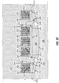
Figure 2C illustrates a cross-sectional view of the self-actuating support assembly ofFigure 2A and2B installed in the internal assembly of the turbomachine ofFigure 1 and in an extended position, according to one or more embodiments disclosed, the self-actuating aspect not forming part of the present invention. -
Figure 2D illustrates another cross-sectional view of the self-actuating support assembly ofFigure 2A and2B installed in the internal assembly of the turbomachine ofFigure 1 and in a seated position, according to one or more embodiments disclosed, the self-actuating aspect not forming part of the present invention. -
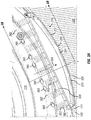
Figure 3A illustrates a perspective view of a remotely-actuated support assembly that may be installed in the internal assembly of the turbo machine ofFigure 1 , according to one or more embodiments of the present invention. -
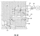
Figure 3B illustrates a cross-sectional view taken alongline 3B-3B of the remotely-actuated support assembly ofFigure 3A installed in the internal assembly of the turbomachine ofFigure 1 , according to one or more embodiments of the present invention. -
Figure 4 is a flowchart of a method for supporting an internal assembly in a casing of a turbomachine, according to one or more embodiments of the present invention. -
Figure 1 illustrates a partial cutaway perspective view of aninternal assembly 110 supported in acasing 120 of aturbomachine 100, according to one or more embodiments. In at least one embodiment, theinternal assembly 110 may be or include, but is not limited to, a bundle, a motor, a pump, or the like, or any combination thereof, and thecasing 120 may be anycasing 120 configured to receive, secure, and/or support theinternal assembly 110. For example, as illustrated inFigure 1 , theinternal assembly 110 may be a modular bundle having one or more compression stages and thecasing 120 may be a compressor casing configured to receive, secure, and/or support the modular bundle. Theinternal assembly 110 may include a firstaxial end portion 112 and a second axial end portion 114, which may also be referred to as aservice end 112 and a non-service end 114, respectively. Thecasing 120 may also include a firstaxial end portion 122 and a secondaxial end portion 124, which may be referred to as aservice end 122 and anon-service end 124, respectively. In at least one embodiment, aninner surface 125 of thecasing 120 may define acavity 121 configured to receive theinternal assembly 110. Thecavity 121 may at least partially extend from theservice end 122 toward thenon-service end 124 of thecasing 120. In at least one embodiment, anouter surface 111 of theinternal assembly 110 and/or theinner surface 125 of thecasing 120 may be generally cylindrical in shape, and at least a portion of theinner surface 125 of thecasing 120 may have a non-uniform or uneven surface topology. - To assemble the
turbomachine 100, theinternal assembly 110 may be inserted through theservice end 122 of thecasing 120 such that the non-service end 114 of theinternal assembly 110 may be positioned or located proximal thenon-service end 124 of thecasing 120 and theservice end 112 of theinternal assembly 110 may be positioned proximal theservice end 122 of thecasing 120. WhileFigure 1 illustrates theinternal assembly 110 and thecasing 120 in a horizontal orientation, the spatial orientation of theinternal assembly 110 and thecasing 120 is merely exemplary. Accordingly, it may be appreciated that theinternal assembly 110 may be inserted through theservice end 122 of thecasing 120 while theinternal assembly 110 and thecasing 120 are in any spatial orientation. For example, theinternal assembly 110 and thecasing 120 may be horizontally-oriented, vertically-oriented, or any position therebetween during the assembly of theturbomachine 100. - In at least one embodiment, the
non-service end 124 of thecasing 120 and/or the non-service end 114 of theinternal assembly 110 may be inaccessible during the assembly of theturbomachine 100. For example, as illustrated inFigure 1 , thenon-service end 124 of thecasing 120 may be a closed axial end of thecasing 120. In another example, a separate system or assembly, such as a motor assembly (not shown), may be coupled with and/or disposed proximal thenon-service end 124 of thecasing 120, thereby impeding access to the non-service end 114 of theinternal assembly 110. The inability to access the non-service end 114 of theinternal assembly 110 may prevent adjustments and/or internal measurements (e.g., positional measurements) of theinternal assembly 110 and/or components thereof via thenon-service end 124 of thecasing 120. - The
turbomachine 100 may include asupport system 150 configured to facilitate the insertion of theinternal assembly 110 into thecasing 120 and/or the removal of theinternal assembly 110 from thecasing 120. For example, thesupport system 150 may be configured to support theinternal assembly 110 during the insertion and/or removal thereof into and/or from thecasing 120. Thesupport system 150 may also be configured to prevent anouter surface 111 of theinternal assembly 110 from contacting or engaging theinner surface 125 of thecasing 120, thereby substantially preventing damage to theinternal assembly 110 and/or thecasing 120. Thesupport system 150 may also be configured to align theinternal assembly 110 within thecasing 120. Thesupport system 150 may include one or more support assemblies (three are shown 132, 134, 136) disposed at various axial and/or circumferential positions along and/or about theinternal assembly 110. As further described herein, the support assemblies 132, 134, 136 may at least partially extend or protrude radially outward from theouter surface 111 of theinternal assembly 110 to support theinternal assembly 110 and/or substantially prevent theinternal assembly 110 from contacting thecasing 120. WhileFigure 1 illustrates threesupport assemblies support assemblies support assemblies support system 150 may include any number of thesupport assemblies internal assembly 110. - In at least one embodiment, one or more of the
support assemblies internal assembly 110 and configured to support or suspend theinternal assembly 110 within thecasing 120 and/or prevent contact between the lower portion of theinternal assembly 110 and thecasing 120. For example, as illustrated inFigure 1 , a firstlower support assembly 132 may be disposed at the lower portion of theinternal assembly 110 near or proximal the non-service end 114, and a secondlower support assembly 134 may be disposed at the lower portion of theinternal assembly 110 between theservice end 112 and the non-service end 114. Contact between the lower portion of theinternal assembly 110 and thecasing 120 may result from a mass or weight of theinternal assembly 110. In another embodiment, one or more of thesupport assemblies internal assembly 110 and configured to prevent contact between the upper portion of theinternal assembly 110 and thecasing 120. For example, as illustrated inFigure 1 , anupper support assembly 136 may be disposed at the upper portion of theinternal assembly 110 to prevent contact between theinternal assembly 110 and thecasing 120. - In at least one embodiment, the
lower support assemblies internal assembly 110 within thecasing 120. For example, thelower support assemblies internal assembly 110 with thecasing 120 during the installation and/or removal thereof. Thelower support assemblies outer surface 111 of theinternal assembly 110 and apply or exert a biasing force or load in the radially outward direction to align and/or position theinternal assembly 110 within thecasing 120. In at least one embodiment, theupper support assembly 136 may be configured to at least partially counter the biasing force of thelower support assemblies internal assembly 110 and thecasing 120. For example, the biasing force from thelower support assemblies internal assembly 110 to contact thecasing 120. Accordingly, theupper support assembly 136 may be provided to counter the biasing force applied by thelower support assemblies internal assembly 110 and thecasing 120. - In at least one embodiment, the
support system 150 described herein may be utilized to monitor and/or indicate contact between theinternal assembly 110 and thecasing 120. For example, thesupport assemblies internal assembly 110 and thecasing 120. In another example, thesupport assemblies support assemblies internal assembly 110 and thecasing 120. Accordingly, contact between theinternal assembly 110 and thecasing 120 may be monitored and/or indicated by measuring the electrical continuity therebetween. - One or more of the
support assemblies turbomachine 100 ofFigure 1 may be a self-actuatingsupport assembly 200 illustrated inFigures 2A-2D . The self-actuatingsupport assembly 200 may include asupport member 210 slidably disposed in arecess 216 extending radially inward from theouter surface 111 of theinternal assembly 110. Thesupport member 210 may include acontact member 220 and abacking member 230 coupled with one another. For example, as illustrated inFigure 2B , thecontact member 220 may have a lip orprotuberance 270 configured to mate with or engage agroove 272 formed in thebacking member 230. It may be appreciated that thecontact member 220 and thebacking member 230 may be coupled with one another via any other coupling method, system, or device known in the art. For example, thecontact member 220 and thebacking member 230 may be coupled with one another via an adhesive. In an exemplary embodiment, at least a portion of thesupport member 210 may be arcuate. For example, one or more components of the support member 210 (e.g., the contact member 220) may be arcuate. In at least one embodiment, thesupport member 210 may be askid pad 210. - In at least one embodiment, an
outer surface 222 of thecontact member 220 may define abeveled edge 274 extending along an outer edge portion thereof. Thebeveled edge 274 may be configured to facilitate the insertion and/or removal of theinternal assembly 110 into and/or from thecasing 120. For example, as previously discussed with reference toFigure 1 , theinner surface 125 of thecasing 120 may have a non-uniform surface topology. Accordingly, thebeveled edge 274 may allow theskid pad 210 to maintain optimal contact with the uneven surface topology of theinner surface 125, thereby facilitating the insertion and/or removal of theinternal assembly 110 into and/or from thecasing 120. - As illustrated in
Figures 2C and2D , theouter surface 222 of thecontact member 220 may be curved radially outward toward theinner surface 125 of thecasing 120. In at least one embodiment, theouter surface 222 of thecontact member 220 may have a radius of curvature substantially equal to that of theouter surface 111 of theinternal assembly 110. In another embodiment, theouter surface 222 of thecontact member 220 may have a radius of curvature substantially equal to that of theinner surface 125 of thecasing 120. As illustrated inFigures 2C and2D , thecontact member 220 may at least partially extend or protrude from therecess 216 and engage or contact theinner surface 125 of thecasing 120. - In at least one embodiment, the
skid pad 210 may be retained in therecess 216 of theinternal assembly 110. For example, thecontact member 220 and thebacking member 230 coupled therewith may be retained within therecess 216 by one or more mechanical fasteners (two are shown 240). Themechanical fasteners 240 may be configured to retain theskid pad 210 within therecess 216 while allowing theskid pad 210 to be slidably disposed in therecess 216. For example, as illustrated inFigures 2C and2D , themechanical fasteners 240 may be or include bolts, such asshoulder bolts 240, having a threadedportion 242, an unthreadedshoulder portion 244, and ahead portion 246. As further illustrated inFigures 2C and2D , theshoulder bolts 240 may extend through theskid pad 210 and be coupled to theinternal assembly 110 via the threadedportion 242. Theshoulder bolts 240 may also extend through theskid pad 210 such that at least a portion of theskid pad 210 may be slidably disposed along theshoulder portion 244 of theshoulder bolts 240. For example, as illustrated inFigures 2C and2D , the backingmember 230 of theskid pad 210 may be slidably disposed along theshoulder portion 244 of theshoulder bolts 240. Thehead portion 246 of theshoulder bolts 240 may retain theskid pad 210 within therecess 216 of theinternal assembly 110. For example, as illustrated inFigure 2C , thehead portion 246 may engage thebacking member 230 to thereby retain theskid pad 210 within therecess 216. -
Figure 2C illustrates the self-actuatingsupport assembly 200 in an extended position where thebacking member 230 may be located or positioned proximal thehead portion 246 of theshoulder bolts 240. The self-actuatingsupport assembly 200 may be held in or urged toward the extended position by one or more biasing members (five are shown 250) disposed between theinternal assembly 110 and thebacking member 230. For example, theinternal assembly 110 may define one or more blind holes orpockets 252 extending radially inward from therecess 216 and configured to receive at least a portion of the biasingmembers 250. As illustrated inFigure 2C , the biasingmembers 250 may be at least partially disposed in thepockets 252 and may at least partially extend into therecess 216 to engage thebacking member 230. The biasingmembers 250 may engage thebacking member 230 to apply or exert a biasing force or load thereto, as indicated byarrow 254. The biasingforce 254 may urge theskid pad 210 radially outward such that thecontact member 220 engages theinner surface 125 of thecasing 120. Accordingly, the biasingforce 254 from the biasingmembers 250 may be applied to theinner surface 125 of thecasing 120. - In at least one embodiment, the biasing
member 250 may be or include any force producing system or device. For example, the biasingmember 250 may be or include one or more electro-mechanical actuators, pneumatic cylinders, elastomeric members, or the like, or any combination thereof. In another example, as illustrated inFigures 2C and2D , the biasingmembers 250 may be or include one or more springs 250. In at least one embodiment, a spring constant of thesprings 250 may be varied such that the biasingforce 254 applied to theskid pad 210 may be optimized. For example, the spring constant of thesprings 250 may be varied to increase or decrease the biasingforce 254 applied to theskid pad 210. It may be appreciated that the spring constant of each of thesprings 250 may be greater than, less than, or equal to one another. In another embodiment, the number ofsprings 250 may be varied to increase or decrease the biasingforce 254 applied to theskid pad 210. For example, the number of thesprings 250 may be increased to correspondingly increase theoverall biasing force 254 applied to theskid pad 210. In another embodiment, the arrangement or position of thesprings 250 may be varied to increase or decrease the biasingforce 254 applied to theskid pad 210. For example, thesprings 250 may be closely packed with one another to thereby increasing theoverall biasing force 254 applied to theskid pad 210. -
Figure 2D illustrates the self-actuatingsupport assembly 200 in a seated position where thebacking member 230 of theskid pad 210 may be located or positioned proximal aninner end surface 215 of therecess 216. An opposing force or load, as indicated byarrow 255, may be applied to theskid pad 210 in a direction opposite to the direction of the biasingforce 254 to at least partially compress thesprings 250 and urge the self-actuatingsupport assembly 200 toward the seated position. In at least one embodiment, with continued reference toFigure 1 , the opposingforce 255 may be applied by thecasing 120 of theturbomachine 100. For example, the opposingforce 255 may be a force applied by thecasing 120 to support a mass of theinternal assembly 110. - As previously discussed with reference to
Figure 1 , thecasing 120 may have an uneven surface topology along theinner surface 125 thereof. Accordingly, as theinternal assembly 110 advances toward thenon-service end 124 of thecasing 120 the uneven surface topology of theinner surface 125 may apply an uneven load to the self-actuatingsupport assembly 200. In at least one embodiment, the arrangement or configuration of thesprings 250 and thebacking member 230 may allow the load applied to the self-actuatingsupport assembly 200 to be distributed or spread to each of thesprings 250 via thebacking member 230. For example, the opposingforce 255 applied to a first portion of thecontact member 220 may be transferred to thebacking member 230, and thebacking member 230 may distribute or spread the opposingforce 255 to each of thesprings 250. Accordingly, each of thesprings 250 may absorb at least a portion of the opposingforce 255 applied to theskid pad 210. - In at least one embodiment, the
contact member 220 may engage theinner surface 125 of thecasing 120 without causing damage (e.g., galling) thereto. For example, during the insertion and/or removal of theinternal assembly 110 from thecasing 120, thecontact member 220 may engage and slide along theinner surface 125 of thecasing 120 without causing damage thereto. In at least one embodiment, thecontact member 220 may be or include one or more low friction materials such as TEFLON®. For example, thecontact member 220 may be completely fabricated from TEFLON® or thecontact member 220 may be fabricated with a TEFLON® coating. In another embodiment, thecontact member 220 may be at least partially deformable or compressible to accommodate the uneven topology of theinner surface 125 of thecasing 120. For example, thecontact member 220 may be or include one or more elastomeric materials, including, but not limited to, one or more synthetic polymers, synthetic elastomers, synthetic rubber, or any combination thereof. - In an exemplary operation of the
support system 150 in the installation of theinternal assembly 110 in thecasing 120, with continued reference toFigure 1 , theinternal assembly 110 may be inserted through theservice end 122 of thecasing 120. Each of thesupport assemblies internal assembly 110 may be the self-actuatingsupport assembly 200 as described with reference toFigures 2A-2D . For example, the self-actuatingsupport assembly 200 may be utilized as theupper support assembly 136 and thelower support assemblies internal assembly 110 may be inserted through theservice end 122 of thecasing 120 such that theupper support assembly 136 and/or thelower support assemblies inner surface 125. As theinternal assembly 110 is inserted through theservice end 122 of thecasing 120 and advanced toward thenon-service end 124, the biasingmembers 250 of thelower support assemblies force 254 to theskid pads 210 to support and/or position theinternal assembly 110 within thecasing 120. Thelower support assemblies internal assembly 110 and thecasing 120. The biasingmembers 250 of theupper support assembly 136 may apply the biasingforce 254 to theskid pad 210 in an opposing radial direction relative to the biasingforce 254 applied by thelower support assemblies internal assembly 110 and thecasing 120. - The
internal assembly 110 may be further advanced toward thenon-service end 124 of thecasing 120 such that the non-service end 114 of theinternal assembly 110 may be positioned or located proximal thenon-service end 124 of thecasing 120 and theservice end 112 of theinternal assembly 110 may be positioned proximal theservice end 122 of thecasing 120. As previously discussed, theinner surface 125 of thecasing 120 may have a non-uniform surface topology. Due to the non-uniform surface topology of theinner surface 125, an inner diameter of thecasing 120 may vary (i.e., increase or decrease) from theservice end 122 toward thenon-service end 124. As thesupport assemblies casing 120 where the inner diameter of thecasing 120 increases, thesupport assemblies Figure 2D ). Further, as thesupport assemblies casing 120 where the inner diameter of thecasing 120 decreases, thesupport assemblies Figure 2C ). Accordingly, as thesupport assemblies inner surface 125, theskid pads 210 of thesupport assemblies Figure 2C ) and the seated position (SeeFigure 2D ) to accommodate variations in the surface topology and/or variations in the inner diameter of thecasing 120. - In at least one embodiment, one or more of the
support assemblies turbomachine 100 ofFigure 1 may be a remotely-actuatedsupport assembly 300 illustrated inFigures 3A and3B . The remotely-actuatedsupport assembly 300 may include asupport member 310 slidably disposed in arecess 316 extending radially inward from theouter surface 111 of theinternal assembly 110. Thesupport member 310 may include acontact member 320 and abacking member 330 coupled with one another. For example, as illustrated inFigure 3B , the backingmember 330 may include a lip orprotuberance 332 configured to mate with or engage agroove 334 formed in thecontact member 320. It may be appreciated that thecontact member 320 and thebacking member 330 may be coupled with one another via any other coupling method, system, or device known in the art. For example, thecontact member 320 and thebacking member 330 may be coupled with one another via an adhesive. In an exemplary embodiment, at least a portion of thesupport member 310 may be arcuate. For example, one or more components of the support member 310 (e.g., the contact member 320) may be arcuate. In at least one embodiment, thesupport member 310 may be askid pad 310. - In at least one embodiment, an
outer surface 322 of thecontact member 320 may define abeveled edge 324 extending along an outer edge portion thereof. Thebeveled edge 324 may be configured to facilitate the insertion and/or removal of theinternal assembly 110 into and/or from thecasing 120. In at least one embodiment, theouter surface 322 of thecontact member 320 may have a radius of curvature similar to that of the outer surface 111 (SeeFigure 3A ) of theinternal assembly 110. In another embodiment, theouter surface 322 of thecontact member 320 may have a radius of curvature similar to that of theinner surface 125 of thecasing 120 to optimize contact or engagement between thecontact member 320 and theinner surface 125. - In at least one embodiment, the
internal assembly 110 may define one ormore pockets 352 extending radially inward from therecess 316. Thebacking member 330 may include one ormore pistons 350 at least partially extending into thepockets 252 defined in theinternal assembly 110. Thepistons 350 may be slidably disposed in thepockets 352 and configured to at least partially control a radial position of thebacking member 330 and thecontact member 320 coupled therewith (i.e., the skid pad 310). The radial position of theskid pad 310 may determine, at least in part, the radial alignment and/or position of theinternal assembly 110 relative to thecasing 120. - In at least one embodiment, the
pistons 350 may form a fluid tight seal with thepockets 352. For example, as shown inFigure 3B , thepistons 350 may include one or morecircumferential channels 354 having one or more seals 356 (e.g., O-rings) at least partially disposed therein and configured to provide the fluid tight seal between thepistons 350 and thepockets 352. In addition to, or in substitution of theseals 356, one or more guiding rings (not shown) configured to maintain the orientation of thepistons 350 within thepockets 352 may be disposed in thechannels 354. - In at least one embodiment, the
internal assembly 110 may define one ormore ports 360 in theservice end 112 and/or the non-service end 144 (seeFigure 1 ) of theinternal assembly 110. At least one of theports 360 may be fluidly coupled with at least one of thepockets 352. For example, theinternal assembly 110 may define one or morefluid passages 362 configured to fluidly couple at least one of theports 360 with at least one of thepockets 352. In at least one embodiment, theports 360 may be configured to receive a fluid, such as a hydraulic fluid, and direct the hydraulic fluid to thepockets 352 via thefluid passages 362. The hydraulic fluid directed to thepockets 352 may apply or exert a biasing force or load to thepistons 350 slidably disposed therein, as indicated byarrow 358. The biasingforce 358 may actuate thepistons 350 of theskid pad 310 in a radially outward direction, thereby causing thecontact member 320 to engage theinner surface 125 of thecasing 120. Thecontact member 320 may engage and apply the biasingforce 358 to the inner surface of thecasing 120 to radially align and/or position theinternal assembly 110 within thecasing 120. - In at least one embodiment, each of the
pistons 350 may be actuated independently. For example, thefluid passages 362 may fluidly couple one of thepockets 352 with at least one of theports 360. In another embodiment, a plurality of thepistons 350 may be actuated with one another. For example, thefluid passages 362 may fluidly couple a plurality of thepockets 352 with at least one of theports 360. - As illustrated in
Figure 3B , one or more valves (one is shown 370) may be fluidly coupled with at least one of theports 360. In at least one embodiment, thevalve 370 may be a regulator valve configured to control a flow of the hydraulic fluid flowing therethrough. In another embodiment, thevalve 370 may be or include a quick disconnect valve or a component thereof. The quick disconnect valve may be configured to detachably couple theports 360 with one or more devices, assemblies, sources of hydraulic fluid, or any combination thereof. For example, as illustrated inFigure 3B , thevalve 370 may be a male component of the quick disconnect valve configured to engage a female component (not shown) of the quick disconnect valve. It may be appreciated that thevalve 370 may be any valve capable of fluidly coupling theports 360 with the one or more devices, assemblies, sources of hydraulic fluid, or any combination thereof. - In at least one embodiment, the
valve 370 may fluidly couple theports 360 with anaccumulator 380. For example, as illustrated inFigure 3B , thevalve 370 may be fluidly coupled with theaccumulator 380 via one or more lines, as indicated byarrow 382. Theaccumulator 380 may direct the hydraulic fluid to thepockets 352 to apply the biasingforce 358 to theskid pad 310. Theaccumulator 380 may also maintain the hydraulic fluid in thepockets 352 at a pressure sufficient to apply the biasingforce 358 to theskid pad 310 to support and/or position theinternal assembly 110. Theaccumulator 380 may also be configured to maintain the pressure of the hydraulic fluid while allowing theskid pad 310 to be actuated radially inward or outward. For example, as theinternal assembly 110 advances toward thenon-service end 124 of thecasing 120, the uneven surface topology of theinner surface 125 may actuate thepistons 350 radially inward, thereby ejecting at least a portion of the hydraulic fluid from thepockets 352 to theaccumulator 380 via thefluid passages 362 and theports 360. Theaccumulator 380 may receive the hydraulic fluid from theports 360 while maintaining the remaining portion of the hydraulic fluid contained in thepockets 352 at a pressure sufficient to support theinternal assembly 110 and/or preventing theinternal assembly 110 from contacting thecasing 120. Similarly, when thepistons 350 are actuated radially outward in response to the uneven surface topology of thecasing 120, theaccumulator 380 may direct the hydraulic fluid to thepockets 352 to maintain the pressure sufficient to support theinternal assembly 110 and/or prevent theinternal assembly 110 from contacting thecasing 120. - In another exemplary operation of the
support system 150 in the installation of theinternal assembly 110 in thecasing 120, with continued reference toFigure 1 , theinternal assembly 110 may be inserted through theservice end 122 of thecasing 120. Any one or more of thesupport assemblies internal assembly 110 may be the self-actuatingsupport assembly 200 as described with reference toFigures 2A-2D and/or the remotely-actuatedsupport assembly 300 as described with reference toFigures 3A and3B . For example, the self-actuatingsupport assembly 200 described inFigures 2A-2D may be utilized as theupper support assembly 136, and the remotely-actuatedsupport assembly 300 described inFigures 3A and3B may be utilized as thelower support assemblies - To assemble the
turbomachine 100, theinternal assembly 110 may be inserted through theservice end 122 of thecasing 120 such that theupper support assembly 136 and/or thelower support assemblies inner surface 125 of thecasing 120. The hydraulic fluid from theaccumulator 380 may be directed to thepockets 352 of thelower support assemblies ports 360 and thefluid passages 362. The hydraulic fluid directed to thepockets 352 may actuate theskid pads 310 of thelower support assemblies contact members 320 of thelower support assemblies inner surface 125 of thecasing 120 and apply the biasingforce 358 thereto. The biasingforce 358 from thelower support assemblies internal assembly 110 within thecasing 120 and prevent the lower portion of theinternal assembly 110 from contacting thecasing 120. The biasingmembers 250 of theupper support assembly 136 may apply the biasingforce 254 to theskid pad 210 thereof to oppose the biasingforce 358 applied by thelower assemblies internal assembly 110 and thecasing 120. - The
internal assembly 110 may be further advanced toward thenon-service end 124 of thecasing 120 such that the non-service end 114 of theinternal assembly 110 may be positioned or located proximal thenon-service end 124 of thecasing 120 and theservice end 112 of theinternal assembly 110 may be positioned proximal theservice end 122 of thecasing 120. As previously discussed, theinner surface 125 of thecasing 120 may have a non-uniform surface topology, and the inner diameter of thecasing 120 may vary (i.e., increase or decrease) from theservice end 122 toward thenon-service end 124. As thelower support assemblies casing 120 where the inner diameter of thecasing 120 decreases, thelower support assemblies pockets 352 to theaccumulator 380 via thefluid passages 362 and theports 360. Theaccumulator 380 may receive the hydraulic fluid while maintaining the pressure of the hydraulic fluid remaining in thepockets 352, thereby supporting and/or positioning theinternal assembly 110 within thecasing 120. Further, as thelower support assemblies casing 120 where the inner diameter of thecasing 120 increases, thelower support assemblies accumulator 380 may direct the hydraulic fluid to thepockets 352 to support and/or position theinternal assembly 110. Accordingly, as theinternal assembly 110 advances toward thenon-service end 124 of the casing, theaccumulator 380 may maintain the pressure of the hydraulic fluid in thepockets 352 as thelower support assemblies casing 120. As previously discussed, the upper support assembly 136 (i.e., the self-actuating support assembly 200) may oscillate between the extended position (SeeFigure 2C ) and the seated position (SeeFigure 2D ) to accommodate the variations in the surface topology and/or the variations in the inner diameter of thecasing 120. -
Figure 4 is a flowchart of amethod 400 for supporting an internal assembly in a casing of a turbomachine, according to one or more embodiments. Themethod 400 may include directing a hydraulic fluid from an accumulator to a pocket to apply a biasing force to a piston of a support member slidably disposed in the pocket, as shown at 402. Themethod 400 may also include actuating the support member radially outward such that the support member engages an inner surface of the casing, as shown at 404. Themethod 400 may further include applying the biasing force to the inner surface of the casing with the support member to thereby support the internal assembly in the casing, as shown at 406.
Claims (11)
- An assembly comprising an internal assembly (110) and a support assembly (300) for supporting the internal assembly (110) in a casing (120) of a turbomachine (100), characterized in that:the support assembly (300) comprises a support member (310) slidably disposed in a recess (316) formed in the internal assembly, a pocket (352) extending radially inward from the recess, the support member (310) configured to engage an inner surface (125) of the casing;the assembly further comprising:
an accumulator (380) fluidly coupled with the pocket (352) and configured to direct a hydraulic fluid to the pocket to thereby apply a biasing force to a piston (350) of the support member (310) slidably disposed in the pocket (352). - The assembly of claim 1, wherein the support member (310) comprises an insulating material configured to electrically isolate the internal assembly (110) from the casing (120).
- The assembly of claim 1, wherein the support member (310) comprises a contact member (320) and a backing member (330) coupled with one another, the contact member (320) configured to engage the inner surface (125) of the casing (120).
- The assembly of claim 3, wherein the contact member (320) defines a protuberance (332) configured to mate with a groove (334) formed in the backing member (330) to thereby couple the contact member with the backing member.
- The assembly of claim 3, wherein an outer surface (322) of the contact member (320) has a radius of curvature equal to a radius of curvature of the inner surface (125) of the casing (120).
- The assembly of claim 1, wherein the internal assembly (110) defines a port (360) in an axial end portion thereof and further defines a passage (362) fluidly coupling the port (360) with the pocket (352), the accumulator (380) fluidly coupled with the pocket via the port and the passage.
- The assembly of claim 6, further comprising a valve (370) fluidly coupled with the port (360) and configured to fluidly couple the port with the accumulator (380).
- A method (400) for supporting an internal assembly (110) in a casing (120) of a turbomachine, comprising:directing a hydraulic fluid from an accumulator (380) to a pocket (352) to apply a biasing force to a piston (350) of a support member (310) slidably disposed in the pocket, the support member slidably disposed in a recess (316) formed in the internal assembly, and the pocket extending radially inward from the recess;actuating the support member (310) radially outward such that the support member engages an inner surface (125) of the casing (120); andapplying the biasing force to the inner surface (125) of the casing with the support member (310) to thereby support the internal assembly (110) in the casing (120).
- The method (400) of claim 8, further comprising:actuating the support member (310) radially inward;directing the hydraulic fluid from the pocket (352) to the accumulator (380); andmaintaining the hydraulic fluid in the pocket (352) at a pressure sufficient to support the internal assembly (110).
- The method (400) of claim 8, wherein the support member (310) comprises an insulating material configured to electrically isolate the internal assembly (110) from the casing (120).
- The method (400) of claim 10, further comprising monitoring contact between the internal assembly (110) and the casing (120) by measuring electrical continuity between the internal assembly (110) and the casing (120).
Applications Claiming Priority (3)
| Application Number | Priority Date | Filing Date | Title |
|---|---|---|---|
| US201361871449P | 2013-08-29 | 2013-08-29 | |
| US14/456,040 US9624933B2 (en) | 2013-08-29 | 2014-08-11 | Support assembly for a turbomachine |
| PCT/US2014/051327 WO2015031083A1 (en) | 2013-08-29 | 2014-08-15 | Support assembly for a turbomachine |
Publications (3)
| Publication Number | Publication Date |
|---|---|
| EP3039267A1 EP3039267A1 (en) | 2016-07-06 |
| EP3039267A4 EP3039267A4 (en) | 2017-03-29 |
| EP3039267B1 true EP3039267B1 (en) | 2020-01-08 |
Family
ID=52587210
Family Applications (1)
| Application Number | Title | Priority Date | Filing Date |
|---|---|---|---|
| EP14839414.1A Active EP3039267B1 (en) | 2013-08-29 | 2014-08-15 | Support assembly for a turbomachine |
Country Status (3)
| Country | Link |
|---|---|
| US (2) | US9624933B2 (en) |
| EP (1) | EP3039267B1 (en) |
| WO (1) | WO2015031083A1 (en) |
Families Citing this family (2)
| Publication number | Priority date | Publication date | Assignee | Title |
|---|---|---|---|---|
| FR3096728B1 (en) * | 2019-05-29 | 2022-01-28 | Thermodyn | Compressor cartridge, motor-compressor and method of assembling such a motor-compressor |
| US12071860B2 (en) | 2022-03-30 | 2024-08-27 | Ge Infrastructure Technology Llc | System and method for aligning casing wall of turbomachine |
Family Cites Families (17)
| Publication number | Priority date | Publication date | Assignee | Title |
|---|---|---|---|---|
| CH524087A (en) | 1970-11-18 | 1972-06-15 | Bbc Brown Boveri & Cie | Cylinder ring seal |
| US3764098A (en) | 1971-02-16 | 1973-10-09 | Westinghouse Electric Corp | Turbine with load force determining device |
| CH528668A (en) * | 1971-03-11 | 1972-09-30 | Bbc Brown Boveri & Cie | Turbomachine support device |
| CH553921A (en) * | 1972-07-13 | 1974-09-13 | Bbc Sulzer Turbomaschinen | ADJUSTING DEVICE FOR THE VANES OF AN AXIAL COMPRESSOR. |
| US3860359A (en) * | 1973-07-30 | 1975-01-14 | Curtiss Wright Corp | Mounting system for gas turbine power unit |
| CA1098894A (en) * | 1979-07-19 | 1981-04-07 | Inco Limited | Non-rotating spring loaded stabilizer |
| US4612987A (en) * | 1985-08-20 | 1986-09-23 | Cheek Alton E | Directional drilling azimuth control system |
| WO1988010355A1 (en) * | 1987-06-16 | 1988-12-29 | Preussag Aktiengesellschaft | Device for guiding a drilling tool and/or pipe string |
| US5560439A (en) * | 1995-04-17 | 1996-10-01 | Delwiche; Robert A. | Method and apparatus for reducing the vibration and whirling of drill bits and the bottom hole assembly in drilling used to drill oil and gas wells |
| US6629568B2 (en) * | 2001-08-03 | 2003-10-07 | Schlumberger Technology Corporation | Bi-directional grip mechanism for a wide range of bore sizes |
| EP1818509A1 (en) | 2006-02-09 | 2007-08-15 | Siemens Aktiengesellschaft | Guide vane assembly |
| US8182207B2 (en) * | 2008-03-17 | 2012-05-22 | General Electric Company | Inner turbine shell support configuration and methods |
| US8113771B2 (en) * | 2009-03-20 | 2012-02-14 | General Electric Company | Spring system designs for active and passive retractable seals |
| US20130034436A1 (en) * | 2011-08-02 | 2013-02-07 | General Electric Company | Systems, Method, and Apparatus for Modifying a Turbine Casing |
| DE102012206855A1 (en) * | 2011-11-09 | 2013-05-16 | Bosch Mahle Turbo Systems Gmbh & Co. Kg | Variable turbine structure for supercharger, has adjusting ring provided with partially coaxial shovel bearing ring, and spring unit elastically pre-tensioning adjusting ring in radial direction to another shovel bearing ring |
| US8967951B2 (en) * | 2012-01-10 | 2015-03-03 | General Electric Company | Turbine assembly and method for supporting turbine components |
| RU2626096C1 (en) * | 2013-12-04 | 2017-07-21 | Халлибертон Энерджи Сервисез, Инк. | Vibration damper |
-
2014
- 2014-08-11 US US14/456,040 patent/US9624933B2/en active Active
- 2014-08-15 EP EP14839414.1A patent/EP3039267B1/en active Active
- 2014-08-15 WO PCT/US2014/051327 patent/WO2015031083A1/en not_active Ceased
-
2017
- 2017-03-06 US US15/450,252 patent/US10767660B2/en active Active
Non-Patent Citations (1)
| Title |
|---|
| None * |
Also Published As
| Publication number | Publication date |
|---|---|
| EP3039267A4 (en) | 2017-03-29 |
| WO2015031083A1 (en) | 2015-03-05 |
| US20170175771A1 (en) | 2017-06-22 |
| US9624933B2 (en) | 2017-04-18 |
| US10767660B2 (en) | 2020-09-08 |
| EP3039267A1 (en) | 2016-07-06 |
| US20150078880A1 (en) | 2015-03-19 |
Similar Documents
| Publication | Publication Date | Title |
|---|---|---|
| US9695940B2 (en) | Bidirectional lift-off circumferential shaft seal segment and a shaft seal including a plurality of the segments | |
| TWI734740B (en) | Rotary union with expanding ring | |
| EP3695155B1 (en) | Multiple passage rotary union | |
| EP3080490B1 (en) | Single seal ring stuffing box | |
| US7909147B1 (en) | Low drag failsafe brake | |
| EP2891836A1 (en) | Mechanical seal device | |
| CN101983279A (en) | Unison ring assembly for an axial compressor casing | |
| CN114508592B (en) | Recoverable gas sealing device and method | |
| US20110127725A1 (en) | Pressure-balanced floating seal housing assembly and method | |
| EP2388465A1 (en) | Axial loading device and method for magnetically-supported rotor systems | |
| JP6174248B2 (en) | Brake device for elevator hoisting machine | |
| US20110158802A1 (en) | Shear ring casing coupler device | |
| KR20140018159A (en) | Rotary union pressure controlled seal actuator | |
| US10767660B2 (en) | Support assembly for a turbomachine | |
| US20130221622A1 (en) | Cartridge and related methods | |
| EP3334896B1 (en) | Blowout preventer packing assembly | |
| JP7273849B2 (en) | Seal structure | |
| CN102341628B (en) | Labyrinth seal bushing for a turbine and method for installing a labyrinth seal arrangement with a labyrinth seal bushing | |
| US20200088301A1 (en) | Abradable seal | |
| US4500096A (en) | Turbine shaft seal assembly | |
| KR20150103089A (en) | Large compressor bundle assembly | |
| US20150345322A1 (en) | Vane support systems | |
| RU131827U1 (en) | RADIAL BEARING ASSEMBLY | |
| EP3673179A1 (en) | Actuator bearing arrangement | |
| RU2634510C1 (en) | End contact seal of turbomachine rotor |
Legal Events
| Date | Code | Title | Description |
|---|---|---|---|
| PUAI | Public reference made under article 153(3) epc to a published international application that has entered the european phase |
Free format text: ORIGINAL CODE: 0009012 |
|
| 17P | Request for examination filed |
Effective date: 20160129 |
|
| AK | Designated contracting states |
Kind code of ref document: A1 Designated state(s): AL AT BE BG CH CY CZ DE DK EE ES FI FR GB GR HR HU IE IS IT LI LT LU LV MC MK MT NL NO PL PT RO RS SE SI SK SM TR |
|
| AX | Request for extension of the european patent |
Extension state: BA ME |
|
| DAX | Request for extension of the european patent (deleted) | ||
| A4 | Supplementary search report drawn up and despatched |
Effective date: 20170301 |
|
| RIC1 | Information provided on ipc code assigned before grant |
Ipc: F02C 7/20 20060101AFI20170223BHEP Ipc: F01D 25/28 20060101ALI20170223BHEP |
|
| RAP1 | Party data changed (applicant data changed or rights of an application transferred) |
Owner name: RANZ, ANDREW J. Owner name: MAIER, WILLIAM C. Owner name: JOHNSON, JOEL D. Owner name: PEER, DAVID J. Owner name: DRESSER-RAND COMPANY |
|
| STAA | Information on the status of an ep patent application or granted ep patent |
Free format text: STATUS: EXAMINATION IS IN PROGRESS |
|
| 17Q | First examination report despatched |
Effective date: 20190115 |
|
| GRAP | Despatch of communication of intention to grant a patent |
Free format text: ORIGINAL CODE: EPIDOSNIGR1 |
|
| STAA | Information on the status of an ep patent application or granted ep patent |
Free format text: STATUS: GRANT OF PATENT IS INTENDED |
|
| INTG | Intention to grant announced |
Effective date: 20191018 |
|
| GRAS | Grant fee paid |
Free format text: ORIGINAL CODE: EPIDOSNIGR3 |
|
| GRAA | (expected) grant |
Free format text: ORIGINAL CODE: 0009210 |
|
| STAA | Information on the status of an ep patent application or granted ep patent |
Free format text: STATUS: THE PATENT HAS BEEN GRANTED |
|
| AK | Designated contracting states |
Kind code of ref document: B1 Designated state(s): AL AT BE BG CH CY CZ DE DK EE ES FI FR GB GR HR HU IE IS IT LI LT LU LV MC MK MT NL NO PL PT RO RS SE SI SK SM TR |
|
| REG | Reference to a national code |
Ref country code: GB Ref legal event code: FG4D |
|
| REG | Reference to a national code |
Ref country code: CH Ref legal event code: EP |
|
| REG | Reference to a national code |
Ref country code: DE Ref legal event code: R096 Ref document number: 602014059831 Country of ref document: DE |
|
| REG | Reference to a national code |
Ref country code: IE Ref legal event code: FG4D |
|
| REG | Reference to a national code |
Ref country code: AT Ref legal event code: REF Ref document number: 1223009 Country of ref document: AT Kind code of ref document: T Effective date: 20200215 |
|
| REG | Reference to a national code |
Ref country code: CH Ref legal event code: NV Representative=s name: SIEMENS SCHWEIZ AG, CH Ref country code: CH Ref legal event code: PUE Owner name: DRESSER-RAND COMPANY, US Free format text: FORMER OWNER: MAIER, WILLIAM C., US |
|
| RAP2 | Party data changed (patent owner data changed or rights of a patent transferred) |
Owner name: DRESSER-RAND COMPANY |
|
| REG | Reference to a national code |
Ref country code: NL Ref legal event code: MP Effective date: 20200108 |
|
| REG | Reference to a national code |
Ref country code: DE Ref legal event code: R081 Ref document number: 602014059831 Country of ref document: DE Owner name: SIEMENS ENERGY, INC., ORLANDO, US Free format text: FORMER OWNERS: DRESSER-RAND COMPANY, OLEAN, N.Y., US; JOHNSON, JOEL D., BRADFORD, PA, US; MAIER, WILLIAM C., ALMOND, NY, US; PEER, DAVID J., OLEAN, NY, US; RANZ, ANDREW J., ENFIELD, CT, US Ref country code: DE Ref legal event code: R082 Ref document number: 602014059831 Country of ref document: DE Representative=s name: MAIER, DANIEL OLIVER, DIPL.-ING. UNIV., DE Ref country code: DE Ref legal event code: R081 Ref document number: 602014059831 Country of ref document: DE Owner name: DRESSER-RAND COMPANY, OLEAN, US Free format text: FORMER OWNERS: DRESSER-RAND COMPANY, OLEAN, N.Y., US; JOHNSON, JOEL D., BRADFORD, PA, US; MAIER, WILLIAM C., ALMOND, NY, US; PEER, DAVID J., OLEAN, NY, US; RANZ, ANDREW J., ENFIELD, CT, US |
|
| REG | Reference to a national code |
Ref country code: LT Ref legal event code: MG4D |
|
| PG25 | Lapsed in a contracting state [announced via postgrant information from national office to epo] |
Ref country code: NO Free format text: LAPSE BECAUSE OF FAILURE TO SUBMIT A TRANSLATION OF THE DESCRIPTION OR TO PAY THE FEE WITHIN THE PRESCRIBED TIME-LIMIT Effective date: 20200408 Ref country code: PT Free format text: LAPSE BECAUSE OF FAILURE TO SUBMIT A TRANSLATION OF THE DESCRIPTION OR TO PAY THE FEE WITHIN THE PRESCRIBED TIME-LIMIT Effective date: 20200531 Ref country code: RS Free format text: LAPSE BECAUSE OF FAILURE TO SUBMIT A TRANSLATION OF THE DESCRIPTION OR TO PAY THE FEE WITHIN THE PRESCRIBED TIME-LIMIT Effective date: 20200108 Ref country code: FI Free format text: LAPSE BECAUSE OF FAILURE TO SUBMIT A TRANSLATION OF THE DESCRIPTION OR TO PAY THE FEE WITHIN THE PRESCRIBED TIME-LIMIT Effective date: 20200108 Ref country code: NL Free format text: LAPSE BECAUSE OF FAILURE TO SUBMIT A TRANSLATION OF THE DESCRIPTION OR TO PAY THE FEE WITHIN THE PRESCRIBED TIME-LIMIT Effective date: 20200108 Ref country code: LT Free format text: LAPSE BECAUSE OF FAILURE TO SUBMIT A TRANSLATION OF THE DESCRIPTION OR TO PAY THE FEE WITHIN THE PRESCRIBED TIME-LIMIT Effective date: 20200108 |
|
| PG25 | Lapsed in a contracting state [announced via postgrant information from national office to epo] |
Ref country code: BG Free format text: LAPSE BECAUSE OF FAILURE TO SUBMIT A TRANSLATION OF THE DESCRIPTION OR TO PAY THE FEE WITHIN THE PRESCRIBED TIME-LIMIT Effective date: 20200408 Ref country code: IS Free format text: LAPSE BECAUSE OF FAILURE TO SUBMIT A TRANSLATION OF THE DESCRIPTION OR TO PAY THE FEE WITHIN THE PRESCRIBED TIME-LIMIT Effective date: 20200508 Ref country code: GR Free format text: LAPSE BECAUSE OF FAILURE TO SUBMIT A TRANSLATION OF THE DESCRIPTION OR TO PAY THE FEE WITHIN THE PRESCRIBED TIME-LIMIT Effective date: 20200409 Ref country code: SE Free format text: LAPSE BECAUSE OF FAILURE TO SUBMIT A TRANSLATION OF THE DESCRIPTION OR TO PAY THE FEE WITHIN THE PRESCRIBED TIME-LIMIT Effective date: 20200108 Ref country code: LV Free format text: LAPSE BECAUSE OF FAILURE TO SUBMIT A TRANSLATION OF THE DESCRIPTION OR TO PAY THE FEE WITHIN THE PRESCRIBED TIME-LIMIT Effective date: 20200108 Ref country code: HR Free format text: LAPSE BECAUSE OF FAILURE TO SUBMIT A TRANSLATION OF THE DESCRIPTION OR TO PAY THE FEE WITHIN THE PRESCRIBED TIME-LIMIT Effective date: 20200108 |
|
| REG | Reference to a national code |
Ref country code: DE Ref legal event code: R097 Ref document number: 602014059831 Country of ref document: DE |
|
| PG25 | Lapsed in a contracting state [announced via postgrant information from national office to epo] |
Ref country code: ES Free format text: LAPSE BECAUSE OF FAILURE TO SUBMIT A TRANSLATION OF THE DESCRIPTION OR TO PAY THE FEE WITHIN THE PRESCRIBED TIME-LIMIT Effective date: 20200108 Ref country code: DK Free format text: LAPSE BECAUSE OF FAILURE TO SUBMIT A TRANSLATION OF THE DESCRIPTION OR TO PAY THE FEE WITHIN THE PRESCRIBED TIME-LIMIT Effective date: 20200108 Ref country code: SK Free format text: LAPSE BECAUSE OF FAILURE TO SUBMIT A TRANSLATION OF THE DESCRIPTION OR TO PAY THE FEE WITHIN THE PRESCRIBED TIME-LIMIT Effective date: 20200108 Ref country code: EE Free format text: LAPSE BECAUSE OF FAILURE TO SUBMIT A TRANSLATION OF THE DESCRIPTION OR TO PAY THE FEE WITHIN THE PRESCRIBED TIME-LIMIT Effective date: 20200108 Ref country code: CZ Free format text: LAPSE BECAUSE OF FAILURE TO SUBMIT A TRANSLATION OF THE DESCRIPTION OR TO PAY THE FEE WITHIN THE PRESCRIBED TIME-LIMIT Effective date: 20200108 Ref country code: SM Free format text: LAPSE BECAUSE OF FAILURE TO SUBMIT A TRANSLATION OF THE DESCRIPTION OR TO PAY THE FEE WITHIN THE PRESCRIBED TIME-LIMIT Effective date: 20200108 Ref country code: RO Free format text: LAPSE BECAUSE OF FAILURE TO SUBMIT A TRANSLATION OF THE DESCRIPTION OR TO PAY THE FEE WITHIN THE PRESCRIBED TIME-LIMIT Effective date: 20200108 |
|
| PLBE | No opposition filed within time limit |
Free format text: ORIGINAL CODE: 0009261 |
|
| STAA | Information on the status of an ep patent application or granted ep patent |
Free format text: STATUS: NO OPPOSITION FILED WITHIN TIME LIMIT |
|
| REG | Reference to a national code |
Ref country code: AT Ref legal event code: MK05 Ref document number: 1223009 Country of ref document: AT Kind code of ref document: T Effective date: 20200108 |
|
| 26N | No opposition filed |
Effective date: 20201009 |
|
| PG25 | Lapsed in a contracting state [announced via postgrant information from national office to epo] |
Ref country code: AT Free format text: LAPSE BECAUSE OF FAILURE TO SUBMIT A TRANSLATION OF THE DESCRIPTION OR TO PAY THE FEE WITHIN THE PRESCRIBED TIME-LIMIT Effective date: 20200108 |
|
| PG25 | Lapsed in a contracting state [announced via postgrant information from national office to epo] |
Ref country code: PL Free format text: LAPSE BECAUSE OF FAILURE TO SUBMIT A TRANSLATION OF THE DESCRIPTION OR TO PAY THE FEE WITHIN THE PRESCRIBED TIME-LIMIT Effective date: 20200108 Ref country code: SI Free format text: LAPSE BECAUSE OF FAILURE TO SUBMIT A TRANSLATION OF THE DESCRIPTION OR TO PAY THE FEE WITHIN THE PRESCRIBED TIME-LIMIT Effective date: 20200108 |
|
| PG25 | Lapsed in a contracting state [announced via postgrant information from national office to epo] |
Ref country code: MC Free format text: LAPSE BECAUSE OF FAILURE TO SUBMIT A TRANSLATION OF THE DESCRIPTION OR TO PAY THE FEE WITHIN THE PRESCRIBED TIME-LIMIT Effective date: 20200108 |
|
| GBPC | Gb: european patent ceased through non-payment of renewal fee |
Effective date: 20200815 |
|
| PG25 | Lapsed in a contracting state [announced via postgrant information from national office to epo] |
Ref country code: LU Free format text: LAPSE BECAUSE OF NON-PAYMENT OF DUE FEES Effective date: 20200815 |
|
| REG | Reference to a national code |
Ref country code: BE Ref legal event code: MM Effective date: 20200831 |
|
| PG25 | Lapsed in a contracting state [announced via postgrant information from national office to epo] |
Ref country code: GB Free format text: LAPSE BECAUSE OF NON-PAYMENT OF DUE FEES Effective date: 20200815 Ref country code: IE Free format text: LAPSE BECAUSE OF NON-PAYMENT OF DUE FEES Effective date: 20200815 Ref country code: BE Free format text: LAPSE BECAUSE OF NON-PAYMENT OF DUE FEES Effective date: 20200831 |
|
| PG25 | Lapsed in a contracting state [announced via postgrant information from national office to epo] |
Ref country code: TR Free format text: LAPSE BECAUSE OF FAILURE TO SUBMIT A TRANSLATION OF THE DESCRIPTION OR TO PAY THE FEE WITHIN THE PRESCRIBED TIME-LIMIT Effective date: 20200108 Ref country code: MT Free format text: LAPSE BECAUSE OF FAILURE TO SUBMIT A TRANSLATION OF THE DESCRIPTION OR TO PAY THE FEE WITHIN THE PRESCRIBED TIME-LIMIT Effective date: 20200108 Ref country code: CY Free format text: LAPSE BECAUSE OF FAILURE TO SUBMIT A TRANSLATION OF THE DESCRIPTION OR TO PAY THE FEE WITHIN THE PRESCRIBED TIME-LIMIT Effective date: 20200108 |
|
| PG25 | Lapsed in a contracting state [announced via postgrant information from national office to epo] |
Ref country code: MK Free format text: LAPSE BECAUSE OF FAILURE TO SUBMIT A TRANSLATION OF THE DESCRIPTION OR TO PAY THE FEE WITHIN THE PRESCRIBED TIME-LIMIT Effective date: 20200108 Ref country code: AL Free format text: LAPSE BECAUSE OF FAILURE TO SUBMIT A TRANSLATION OF THE DESCRIPTION OR TO PAY THE FEE WITHIN THE PRESCRIBED TIME-LIMIT Effective date: 20200108 |
|
| REG | Reference to a national code |
Ref country code: DE Ref legal event code: R082 Ref document number: 602014059831 Country of ref document: DE Representative=s name: ROTH, THOMAS, DIPL.-PHYS. DR., DE |
|
| REG | Reference to a national code |
Ref country code: DE Ref legal event code: R081 Ref document number: 602014059831 Country of ref document: DE Owner name: SIEMENS ENERGY, INC., ORLANDO, US Free format text: FORMER OWNER: DRESSER-RAND COMPANY, OLEAN, N.Y., US |
|
| PGFP | Annual fee paid to national office [announced via postgrant information from national office to epo] |
Ref country code: DE Payment date: 20250827 Year of fee payment: 12 |
|
| PGFP | Annual fee paid to national office [announced via postgrant information from national office to epo] |
Ref country code: IT Payment date: 20250825 Year of fee payment: 12 |
|
| PGFP | Annual fee paid to national office [announced via postgrant information from national office to epo] |
Ref country code: FR Payment date: 20250825 Year of fee payment: 12 |
|
| PGFP | Annual fee paid to national office [announced via postgrant information from national office to epo] |
Ref country code: CH Payment date: 20250901 Year of fee payment: 12 |