EP3038530B1 - Neonatal carbon dioxide measurement system and method - Google Patents
Neonatal carbon dioxide measurement system and method Download PDFInfo
- Publication number
- EP3038530B1 EP3038530B1 EP14839697.1A EP14839697A EP3038530B1 EP 3038530 B1 EP3038530 B1 EP 3038530B1 EP 14839697 A EP14839697 A EP 14839697A EP 3038530 B1 EP3038530 B1 EP 3038530B1
- Authority
- EP
- European Patent Office
- Prior art keywords
- breath
- breaths
- sensor
- analyte
- series
- Prior art date
- Legal status (The legal status is an assumption and is not a legal conclusion. Google has not performed a legal analysis and makes no representation as to the accuracy of the status listed.)
- Active
Links
- 238000000034 method Methods 0.000 title claims description 13
- CURLTUGMZLYLDI-UHFFFAOYSA-N Carbon dioxide Chemical compound O=C=O CURLTUGMZLYLDI-UHFFFAOYSA-N 0.000 title description 74
- 229910002092 carbon dioxide Inorganic materials 0.000 title description 37
- 238000005259 measurement Methods 0.000 title description 22
- 239000001569 carbon dioxide Substances 0.000 title description 2
- 239000012491 analyte Substances 0.000 claims description 27
- 230000004044 response Effects 0.000 claims description 26
- 238000012544 monitoring process Methods 0.000 claims description 12
- 238000005070 sampling Methods 0.000 claims description 10
- 230000001667 episodic effect Effects 0.000 claims description 3
- 239000007789 gas Substances 0.000 description 63
- 230000029058 respiratory gaseous exchange Effects 0.000 description 17
- 239000012080 ambient air Substances 0.000 description 15
- 238000002955 isolation Methods 0.000 description 6
- 239000003570 air Substances 0.000 description 5
- 238000012360 testing method Methods 0.000 description 5
- 238000010586 diagram Methods 0.000 description 4
- 230000000694 effects Effects 0.000 description 4
- 241000717853 Capnia Species 0.000 description 3
- 238000005516 engineering process Methods 0.000 description 3
- 210000004072 lung Anatomy 0.000 description 3
- 239000000243 solution Substances 0.000 description 3
- UGFAIRIUMAVXCW-UHFFFAOYSA-N Carbon monoxide Chemical compound [O+]#[C-] UGFAIRIUMAVXCW-UHFFFAOYSA-N 0.000 description 2
- 239000008280 blood Substances 0.000 description 2
- 210000004369 blood Anatomy 0.000 description 2
- 229910002091 carbon monoxide Inorganic materials 0.000 description 2
- 230000003434 inspiratory effect Effects 0.000 description 2
- 239000000203 mixture Substances 0.000 description 2
- 230000037361 pathway Effects 0.000 description 2
- 238000010926 purge Methods 0.000 description 2
- 241000894006 Bacteria Species 0.000 description 1
- 230000009286 beneficial effect Effects 0.000 description 1
- 230000008901 benefit Effects 0.000 description 1
- 230000035565 breathing frequency Effects 0.000 description 1
- 239000000470 constituent Substances 0.000 description 1
- 230000003111 delayed effect Effects 0.000 description 1
- 230000001419 dependent effect Effects 0.000 description 1
- 238000013461 design Methods 0.000 description 1
- 230000001627 detrimental effect Effects 0.000 description 1
- 238000010790 dilution Methods 0.000 description 1
- 239000012895 dilution Substances 0.000 description 1
- 239000000284 extract Substances 0.000 description 1
- 238000013213 extrapolation Methods 0.000 description 1
- 230000001605 fetal effect Effects 0.000 description 1
- 238000001914 filtration Methods 0.000 description 1
- 238000005399 mechanical ventilation Methods 0.000 description 1
- 238000012552 review Methods 0.000 description 1
- 230000002000 scavenging effect Effects 0.000 description 1
- 230000002269 spontaneous effect Effects 0.000 description 1
- 239000000126 substance Substances 0.000 description 1
- 230000008685 targeting Effects 0.000 description 1
- 230000007704 transition Effects 0.000 description 1
- XLYOFNOQVPJJNP-UHFFFAOYSA-N water Substances O XLYOFNOQVPJJNP-UHFFFAOYSA-N 0.000 description 1
Images


Classifications
-
- A—HUMAN NECESSITIES
- A61—MEDICAL OR VETERINARY SCIENCE; HYGIENE
- A61B—DIAGNOSIS; SURGERY; IDENTIFICATION
- A61B5/00—Measuring for diagnostic purposes; Identification of persons
- A61B5/08—Detecting, measuring or recording devices for evaluating the respiratory organs
- A61B5/083—Measuring rate of metabolism by using breath test, e.g. measuring rate of oxygen consumption
- A61B5/0836—Measuring rate of CO2 production
-
- A—HUMAN NECESSITIES
- A61—MEDICAL OR VETERINARY SCIENCE; HYGIENE
- A61B—DIAGNOSIS; SURGERY; IDENTIFICATION
- A61B5/00—Measuring for diagnostic purposes; Identification of persons
- A61B5/08—Detecting, measuring or recording devices for evaluating the respiratory organs
- A61B5/0816—Measuring devices for examining respiratory frequency
-
- A—HUMAN NECESSITIES
- A61—MEDICAL OR VETERINARY SCIENCE; HYGIENE
- A61B—DIAGNOSIS; SURGERY; IDENTIFICATION
- A61B5/00—Measuring for diagnostic purposes; Identification of persons
- A61B5/08—Detecting, measuring or recording devices for evaluating the respiratory organs
- A61B5/097—Devices for facilitating collection of breath or for directing breath into or through measuring devices
-
- G—PHYSICS
- G01—MEASURING; TESTING
- G01N—INVESTIGATING OR ANALYSING MATERIALS BY DETERMINING THEIR CHEMICAL OR PHYSICAL PROPERTIES
- G01N33/00—Investigating or analysing materials by specific methods not covered by groups G01N1/00 - G01N31/00
- G01N33/48—Biological material, e.g. blood, urine; Haemocytometers
- G01N33/483—Physical analysis of biological material
- G01N33/497—Physical analysis of biological material of gaseous biological material, e.g. breath
Definitions
- the present Disclosure applies to the field of breath measurements and monitoring and specifically to the field of measuring a constituent in the exhaled gas of a patient for the purpose of monitoring the patient's condition.
- the current state-of-the-art measurement technology may not provide an accurate or reliable measurement during fast breathing patterns because the response time of the sensor employed is not fast enough to measure the breath parameter.
- Such measurement applications may be those in which continuous monitoring is desired, or in which intermittent monitoring is desired, or in which a one-time breath test is desired.
- In capnometery for example, Infra-Red sensors are used to measure the CO2 in the exhaled breath.
- the sensor can be in line with the patient's exhaled gas stream, or coupled to the exhaled gas stream through a gas sample scavenging tube, typically referred to as a sampling line in the case of mechanical ventilation or a nasal cannula in the case of spontaneous breathing.
- the capnometry sensor With fast breathing patterns the capnometry sensor is usually capable of registering a breath rate, since a waveform of some amplitude is registered for each breath, however, the sensor is not capable of registering a true peak value of CO2 for each breath.
- the breath sample collection apparatus allows mixing of one section of gas with another section of gas, thus disturbing the homogeneity and purity of the different and discrete sections. This mixing occurs in the patient interface components, valves, filters, water traps, the breath sensor itself, connectors and the sampling tubing.
- Capnia Reference: Capnia US Provisional Patent Application Number 61/872,270 , published as US 2015/0065902 A1 .
- the second problem, which is addressed in the present disclosure, is the intrinsic response time of the sensor technology being employed.
- This response time of the sensor is not fast enough to accurately measure the CO2 in a breath when the patient is breathing fast, such as greater than 30 breaths per minute (bpm).
- Gas obtained from the patient travels through the sensor.
- the sensor When expiratory gas is flowing through the sensor, the sensor will respond to the CO2 molecules in the gas, this response known as the signal response.
- the amplitude of the signal response depends on and corresponds to the amount of CO2 molecules or CO2 concentration in the gas sample.
- the sensor signal response is not instantaneous; it can take as long as 400 milliseconds (ms) for the sensor to finish responding to the CO2 molecules in a bolus of gas from a single expiratory cycle.
- capnometry cannot be relied upon for neonatal CO2 monitoring, unless the patient is breathing below 40 or 50 bpm, which often does not occur depending on the patient's age and condition. Some manufacturers of capnometry monitors often state that the device is not for neonatal use for this reason.
- CO2 can be measured in the blood, however, this is invasive and therefore is not a preferred test and is not used for continuous monitoring or repeat testing.
- CO2 can be measured transcutaneously, but these systems have not yet been proven to be reliable in all clinical situations. (See Arch Dis Child Fetal Neonatal Ed. 2006 July; 91(4): F295-F298. Are carbon dioxide detectors useful in neonates? E J Molloy and K Deakins .)
- US 2013/0165806 A1 relates to an apparatus and method for the collection and analysis of a volume of exhaled gas with compensation for the frequency of a breathing parameter.
- a breath sensor such as a capnometer, is used to measure the breathing pattern in real time to capture and isolate a desired portion of the breath in a storage collection compartment.
- the captured gas is sent from the storage compartment through a gas composition analyzer.
- US 5,383,469 A relates to an apparatus for the sampling and analysis of neonatal end-tidal breath for carbon monoxide which includes a syringe and plunger for collecting end-tidal breath, a pump for supporting the syringe and including drive means for incrementally withdrawing the plunger and collecting end tidal breath, and a controller for the pump including a thermistor positionable to respond to the temperature of exhaled breath and generating an electrical signal in response to thermistor temperature.
- a rate detector receives the signal and determines exhalation rate. The signal is delayed in response to exhalation rate and then utilized to energize the pump in incrementally withdrawing the plunger in collecting end tidal breath.
- the pump can also be used in analysis equipment which extracts the end tidal breath sample with a sensor receiving the sample and determining carbon monoxide content.
- the present invention provides a method of measuring a breath analyte as defined in claim 1 and a system for measuring a breath analyte as defined in claim 6.
- Preferred embodiments of the invention are defined in the dependent claims.
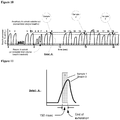
- Figure 1 graphically describes capnometry, when used for non-infant patients.
- breath period BP
- breath rate TE
- TE expiratory time
- the inspiratory part 1 of the breathing curve during which there is basically no signal response from the Capnometer; the beginning of exhalation 2 during which again there is basically no signal response from the Capnometer; a sensor lag time 3 which is a brief lag period or delay before the sensor responds to the first CO2 gas molecules in the exhalation gas seen by the sensor's sensing element; an increasing signal in the middle of exhalation 4 due to the increasing percentage 5 of CO2 being expelled as gas from deeper in the lung is expelled; a plateau 6 representative of alveolar gas and when the sensor has had time to fully respond to the concentration of CO2 molecules; and the, a lag time or delay 7 from the sensor responding to a drop in the CO2 level when exhalation ends and inspiration begins; and a drop 8 in the signal corresponding to the response time of the sensor reacting to no CO2.
- FIGs 2 and 3 the problem of mixing of expiratory alveolar gas with non-alveolar gas is exemplified.
- the effect of an in-line filter is shown as an example.
- Such a filter is often used tp filter humidity or bacteria from the patient along a section of sampling tubing that is being used to draw the sample from the patient.
- the different primary breath gas sections (alveolar 114, upper airway 112 and ambient 110) are shown moving in packets along the sampling pathway 122 to the inlet of a filter 120. The gases from a first breath are shown entering the filter.
- the filter has presumably previously been purged and filled with ambient air, or simply as ambient air inside as baseline condition, and thus is shown filled with ambient air 108, as is the conduit on the outlet side of the filter.
- ambient air 108 as is the conduit on the outlet side of the filter.
- the filter as the different gas sections from the patient's first breath, inspired ambient air 110, airway air 112 and alveolar air 114, travel through the filter, the sections mix with the ambient air in the filter to create mixed gas 130, and exit the filter diluted with the ambient air to create a contaminated airway air sample 132 and a diluted end-tidal sample 134.
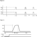
- Figure 4 shows the problem of sensor signal response time, and the potential inability of the sensor to measure the peak gas level. Again in this case capnometry is used as an example, but the measurement can be other analytes.
- the breath rate shown is 60bpm.
- the alveolar gas exhalation time is approximately 250-275msec.
- the sensor response time is > 275msec.
- the peak sensor signal registers 3.8%, while the actual peak percentage is 5.0%. Hence, this system is not capable of measuring CO2 under these clinical conditions.
- a new breath gas sampling and measurement system is described.
- the system stores the appropriate section of exhaled gas from more than one breath, then the system sends the multiple-sample bolus through the sensor.
- the bolus may be composed of end-tidal gas samples from two breaths, each of 150msec in duration, the resultant combined sample therefore being of 300msec in duration.
- the sensor has enough time to register the full amplitude of the CO2 in the bolus, now that the bolus is 300msec long, rather than only 150msec long.
- the pneumatics of the apparatus 150 are described, comprised of a patient inlet Pt, an inlet valve V1, an ambient inlet amb, a breath analyte sensor S, a sample collection compartment 140, a bypass channel 142, a valve V2 at the inlet to the sample collection compartment, a valve V3 at the opposite end of the sample collection compartment, a pump P, and an exhaust E.
- the valves V1, V2 and V3 each may have three ports, a, b, and c, with c port always open, and the system toggling between ports a and b during the collection and test sequence.
- gas from the patient is being drawn into the apparatus by a vacuum pump P, through for example a nasal cannula or sampling tube attached to the patient inlet Pt of the apparatus.
- the patient gas travels around the sample collection area 140 through the bypass 142 (valve V2 port b to valve V3 port b) until an end-tidal sample from a targeted breath is identified by the sensor S and arrives at valve V2.
- the end-tidal sample is allowed into the sample collection area 140, and when it is properly aligned and positioned in that area, the patient gas is once again diverted around this area through the bypass, shown in Figure 7 .
- the sample collection area is filled with two or more end-tidal samples from two or more breaths, as shown in Figure 8 .
- the pump direction is reversed, the patient inlet is closed at Valve V1 and the ambient port amb is open, and the sample bolus is pushed back through the sensor S with ambient air stemming from the exhaust E behind it, and out the ambient port b of valve V1.
- the sensor S measures the CO2 in the sample bolus as it traverses through it, thus registering a et CO2 value.
- the breaths from which the multiple end-tidal samples are collected can be from non-consecutive breaths, in the event of non-steady-state breathing, or episodic breathing, or erratic breathing.
- Breath pattern algorithms are employed to target breaths that are representative of a certain breath type, for example normal tidal volume breaths, and to exclude other breaths, so as to obtain a sample bolus that is truly homogenous of the type of breath being sought for measurement.
- Breath measurement thresholds and other breath criteria are defined, either prospectively, in real time, or retrospectively, or combinations thereof, to establish what is normal and not normal for the particular situation.
- breaths 9, 14, and 19 pass the criteria and are deemed acceptable and are targeted for sample collection.
- the end tidal gas samples from these three targeted breaths are shown collected and stored in the sample compartment 140.
- breath 9 from Figure 10 is shown in more detail. It is desired in this example to acquire and measure the last 150msec of an exhaled breath from more than one breath. The last 150 msec will assure that the sample is a deep lung sample and representative of what is in the blood, even at very fast breath rates. This time can be a default value, or can be configurable automatically or manually, based on the clinical application, and/or the prevailing breathing pattern.
- Figure 12 describes the timing and operation of the valves V2 and V3 in Figures 5-8 in order to shunt, isolate and store these samples in the sample collection area, and to prevent mixing of these samples with other gases, in order to assure a homogeneous sample bolus of end-tidal deep alveolar gas of sufficient volume.
- FIG. 13 shows the valve timing and operation of the operational step shown in Figure 9 , when the end-tidal sample bolus is sent back to the sensor, as well as the sensor's corresponding signal response to the sample bolus.
- 150 ms is the time duration of the desired and selected sample to be captured (the last 150 msec of exhalation)
- t0 the time that the end-of-exhalation of the first good sample exits the sensor S
- t1 t2 - 150msec
- t2 t0 + Xxmsec
- XXmsec time for gas to travel from sensor S outlet to V2 inlet
- a breath rate can be reported using the "clipped" capnometry signal. This can take place for example for one minute, during which time the multiple end-tidal samples from multiple targeted breaths are being collected and stored. Then, after that one minute period, breath rate reporting can be temporarily interrupted for about 3-15 seconds during which time the end-tidal sample bolus is shuttled to a CO2 sensor, and the CO2 level can be reported by the methods described earlier. Then, the above sequence is repeated, such as; breath rate reporting for one minute, 10 second period for etCO reporting, breath rate reporting for one minute, 10 second period for etCO reporting
- Figures 15 through 18 describe an alternative pneumatic sampling and measurement system.
- the pump direction need not be reversed, which may be beneficial with certain types of pump technologies, and to guarantee smooth, consistent pump speed and gas flow rate operation.
- the apparatus comprises an additional inlet valve V5 coupled to the bypass tube 142, V5 with an ambient inlet port amb2, a reverse flow valve V4, a push tube 144, and a reverse tube 146.
- gas from the patient enters the system through the patient inlet Pt, through valve V1, sensor C, valve V5, valve V3, pump P, valve V4 and out exhaust E.
- V2 and V3 switch to shunt the end-tidal sample into the sample collection tube 140.
- the identified and targeted multiple end-tidal samples are collected and properly aligned and positioned in the sample collection area similar to that describe in Figures 5-9 .
- Valve V1 is then switched to the amb inlet so that the patient gases in the various sections of gas pathways other than the sample collection area are purged by ambient air being drawn in through Valve V1, through C, V5, the bypass tube 142, V3, the pump P and V4..
- V2, V3, V4 and V5 switch as shown in Figure 18 , so that ambient air is now drawn in from V5 port b, drawn through V3 port b and the pump, and pushed through V4 port c and b into the sample collection area to push the sample bolus through V2 port c and b, and through the Sensor C, and out V1 to ambient air.
- the systems and methods of the present invention include a single sensor for performing both (a) the initial breathing pattern measurements and sample targeting, and (b) analyte measurement in the multi-sample bolus.
- Systems and methods not covered by the claimed invention can include more than one sensor, for example one for (a) and a second sensor for (b).
- Figures 19-22 show an additional pneumatic configuration. As shown if Figure 19 patient gas flows in through Pt, v1, S1, v5, t1, v2, v3, P, v4 and out E. As shown in Figure 20 , when an end-tidal sample from a targeted breath reaches v2, the valves v2 and v3 are switched to allow the end-tidal sample into the sample collection tube, 141, then the valves are switched back to allow flow through segment 143, thus isolating the end-tidal sample.
- end-tidal samples must be stored until enough end-tidal sample is collected, and that the time durations of each of the captured end-tidal samples, when added together, must add up to a time duration that is at least close to, preferably equal to, and most preferably greater than, the signal response time of the sensor that is being used to measure the gas in the sample bolus.
- the system described herein can be useful for collecting and measuring end-tidal gas samples, as well as samples from other sections of the breath. It can be used for measuring for example CO2 in the breath, or other gases, such as CO, H2, NO, and others. It can be used for measuring other non-gaseous substances in the breath as well as gaseous markers.
- the system disclosed can be used for period, intermittent, semi-continuous, or continuous measurements and monitoring. While overcoming fast breathing patterns is used throughout the foregoing descriptions, the disclosure can be applied to overcome other breathing pattern challenges.
Description
- This application claims the benefit of
U.S. Provisional Application No. 61/872,415, filed August 30th, 2013 - The present Disclosure applies to the field of breath measurements and monitoring and specifically to the field of measuring a constituent in the exhaled gas of a patient for the purpose of monitoring the patient's condition.
- In various breath parameter measurement applications, the current state-of-the-art measurement technology may not provide an accurate or reliable measurement during fast breathing patterns because the response time of the sensor employed is not fast enough to measure the breath parameter. Such measurement applications may be those in which continuous monitoring is desired, or in which intermittent monitoring is desired, or in which a one-time breath test is desired. In capnometery for example, Infra-Red sensors are used to measure the CO2 in the exhaled breath. The sensor can be in line with the patient's exhaled gas stream, or coupled to the exhaled gas stream through a gas sample scavenging tube, typically referred to as a sampling line in the case of mechanical ventilation or a nasal cannula in the case of spontaneous breathing. With fast breathing patterns the capnometry sensor is usually capable of registering a breath rate, since a waveform of some amplitude is registered for each breath, however, the sensor is not capable of registering a true peak value of CO2 for each breath. A review of the product literature available for commercial systems indicates that this limitation does indeed exist.
- In current capnometry systems, especially neonatal capnometry, there are two main technical limitations that prevent accurate measurements. First, the breath sample collection apparatus allows mixing of one section of gas with another section of gas, thus disturbing the homogeneity and purity of the different and discrete sections. This mixing occurs in the patient interface components, valves, filters, water traps, the breath sensor itself, connectors and the sampling tubing. A solution to this technical problem has been described by Capnia (Reference: Capnia
US Provisional Patent Application Number 61/872,270 US 2015/0065902 A1 ). The second problem, which is addressed in the present disclosure, is the intrinsic response time of the sensor technology being employed. This response time of the sensor is not fast enough to accurately measure the CO2 in a breath when the patient is breathing fast, such as greater than 30 breaths per minute (bpm). Gas obtained from the patient travels through the sensor. When expiratory gas is flowing through the sensor, the sensor will respond to the CO2 molecules in the gas, this response known as the signal response. The amplitude of the signal response depends on and corresponds to the amount of CO2 molecules or CO2 concentration in the gas sample. However the sensor signal response is not instantaneous; it can take as long as 400 milliseconds (ms) for the sensor to finish responding to the CO2 molecules in a bolus of gas from a single expiratory cycle. Therefore, if the patient transitions from exhalation to inspiration before the sensor has finished responding to the CO2 molecules in the expiratory gas bolus, the sensor's signal response will not reach the true peak value. This technical problem is called clipping of the signal. Designers can try to extrapolate where the signal would have peaked had the sensor been fast enough, but these extrapolations are inexact, don't take into account the prevailing clinical conditions of the patient, and should not be used in a medical breath test application. An example of this response time limitation follows. - Assuming a patient is breathing at 60 bpm, with a 50/50 Inspiratory/Expiratory time ratio his or her expiratory time will be 500 ms. Assuming the lung is 50% airway deadspace, and assuming a constant expiratory flow rate, the person will expire alveolar gas for half of the expiratory time, or for 250 ms. Now, assuming the sensor has a response time of 300 milliseconds, at the end of exhalation, the sensor will have not fully responded to all of the CO2 molecules in the bolus of alveolar gas, and will have reached only 83% of the true peak value (250/300), assuming the signal response is linear. This means that the sensor signal gets truncated before it reaches the true amplitude of the gas being measured, and in this example may read for 4% CO2 instead of 5% CO2. For these above reasons, it is known in the medical community, that capnometry cannot be relied upon for neonatal CO2 monitoring, unless the patient is breathing below 40 or 50 bpm, which often does not occur depending on the patient's age and condition. Some manufacturers of capnometry monitors often state that the device is not for neonatal use for this reason.
- There are some potential options to circumvent the limitation described above. First, CO2 can be measured in the blood, however, this is invasive and therefore is not a preferred test and is not used for continuous monitoring or repeat testing. Second, CO2 can be measured transcutaneously, but these systems have not yet been proven to be reliable in all clinical situations. (See Arch Dis Child Fetal Neonatal Ed. 2006 July; 91(4): F295-F298. Are carbon dioxide detectors useful in neonates? E J Molloy and K Deakins.)
-
US 2013/0165806 A1 relates to an apparatus and method for the collection and analysis of a volume of exhaled gas with compensation for the frequency of a breathing parameter. A breath sensor, such as a capnometer, is used to measure the breathing pattern in real time to capture and isolate a desired portion of the breath in a storage collection compartment. The captured gas is sent from the storage compartment through a gas composition analyzer. -
US 5,383,469 A relates to an apparatus for the sampling and analysis of neonatal end-tidal breath for carbon monoxide which includes a syringe and plunger for collecting end-tidal breath, a pump for supporting the syringe and including drive means for incrementally withdrawing the plunger and collecting end tidal breath, and a controller for the pump including a thermistor positionable to respond to the temperature of exhaled breath and generating an electrical signal in response to thermistor temperature. A rate detector receives the signal and determines exhalation rate. The signal is delayed in response to exhalation rate and then utilized to energize the pump in incrementally withdrawing the plunger in collecting end tidal breath. The pump can also be used in analysis equipment which extracts the end tidal breath sample with a sensor receiving the sample and determining carbon monoxide content. - Because there is a clinical need for neonatal CO2 measurements, and because of the overwhelming desire for this measurement to be non-invasive and the desire to have the option of continuous or intermittent monitoring, there is a significant unmet need for an accurate, reliable Capnometer for this patient population and other clinical situations and populations in which breathing frequency is relatively fast compared to the sensor being employed.
- The present invention provides a method of measuring a breath analyte as defined in
claim 1 and a system for measuring a breath analyte as defined inclaim 6. Preferred embodiments of the invention are defined in the dependent claims. - It should be noted again that while the disclosure is described for the most part in terms of neonatal capnometry, the same disclosure applies to other breath markers such as O2, and clinical applications other than neonates.
-
-
Figure 1 describes capnometry prior art with a CO2 value in the breath measured as a function of time. -
Figure 2 describes a side view cross section of a prior art filter used for filtering gas collected from a patient. -
Figure 3 describes the prior art filter ofFigure 2 showing the mixing of gas sections that occurs as gas travels through the filter. -
Figure 4 graphically shows the capnometry signal for a series of breaths as a function of time, in which the Capnometer is not able to measure the true peak value of the CO2 in the patient's breath, the subject of which the present disclosure solves. -
Figure 5 describes a schematic of a pneumatic system of the present disclosure used to collect and measure patient gas. -
Figure 6 describes the system ofFigure 5 in which a desired section of gas, for example the end-tidal section, is shunted into an isolation chamber to isolate it from other gases. -
Figure 7 shows the system ofFigures 5-6 wherein the desired sample is fully placed in the isolation chamber and lined up precisely with the inlet to the chamber. -
Figure 8 shows the system ofFigures 5-7 in which desired sections of gas from three separate desired breaths are shunted into the isolation chamber to fill the chamber, without space in-between the sections. -
Figure 9 shows the system ofFigures 5-8 in which the gas sample bolus in the isolation chamber is diverted to a sensor for measurement. -
Figure 10 shows a CO2 breath waveform diagram as a function of time for a series of breaths and threshold criteria for selection and disqualification of breaths to be chosen for analysis. -
Figure 11 shows a close up view of a breath waveform from the series of breaths shown inFigure 10 . -
Figure 12 shows a timing diagram of the valve operation of the system inFigure 5 for the purpose of collecting and isolating the desired end-tidal samples from the desired breaths shown inFigure 10 . -
Figure 13 graphically shows the sensor CO2 signal of the sample bolus from the system inFigure 9 and from the breaths shown inFigure 10 when measured by the sensor, along with a valve timing diagram on the same time scale indicating the valve operation of the system infigure 9 . -
Figure 14 graphically shows the use of an exemplary apparatus as a function of time, with breath rate reporting interspersed by CO2 level reporting, and repeating. -
Figure 15 shows a pneumatic schematic of an alternate pneumatic configuration, in which the sample bolus after collection is diverted to a sensor for measurement without changing the direction of the flow generator. -
Figure 16 shows the system ofFigure 15 with a first sample from a first selected breath entering a sample isolation chamber. -
Figure 17 shows the system ofFigures 15 and 16 , with several samples from several selected breaths now occupying the sample isolation chamber. -
Figure 18 shows the system ofFigures 15-17 in which the sample bolus is diverted to a sensor for compositional analysis. -
Figure 19 shows a pneumatic diagram of an alternate pneumatic configuration in which the flow generator direction remains constant, and shows the state in which flow from the patient is being drawn through the system. -
Figure 20 shows the system ofFigure 19 in which gas is diverted to a second branch for the purpose of shunting and storing a desired sample of gas from a desired breath. -
Figure 21 shows the system ofFigures 19 and 20 in which ambient air is drawn into the system to flush out residual unwanted patient gases. -
Figure 22 shows the system ofFigures 19-21 in which ambient air is drawn in to divert the sample bolus to a sensor for measurement and out another ambient port for exhausting out of the system. -
Figure 1 graphically describes capnometry, when used for non-infant patients. Typically the breath period (BP), breath rate and expiratory time (TE) is slow enough for theCO2 signal 100 from the capnometry sensor to register the full amplitude of theactual CO2 102 in the breath sample, and an accurate etCO2 result is reported. The capnometry curve can be broken down into 7 parts. Theinspiratory part 1 of the breathing curve, during which there is basically no signal response from the Capnometer; the beginning ofexhalation 2 during which again there is basically no signal response from the Capnometer; asensor lag time 3 which is a brief lag period or delay before the sensor responds to the first CO2 gas molecules in the exhalation gas seen by the sensor's sensing element; an increasing signal in the middle ofexhalation 4 due to the increasingpercentage 5 of CO2 being expelled as gas from deeper in the lung is expelled; aplateau 6 representative of alveolar gas and when the sensor has had time to fully respond to the concentration of CO2 molecules; and the, a lag time ordelay 7 from the sensor responding to a drop in the CO2 level when exhalation ends and inspiration begins; and adrop 8 in the signal corresponding to the response time of the sensor reacting to no CO2. The differences between the "Actual CO2"curve 102 and the "Capnometry Signal"curve 100 demonstrate the effects that the response time of the sensor has on the sample measurement. These effects can be subtle and unimportant in many clinical applications, but in others, such as neonatal applications, these effects can be detrimental. Below the graph the sections of gas that is being drawn from the patient, in the case of side stream monitoring, is shown graphically as inspiredambient air 110, expiredairway air 112, and expiredalveolar air 114. - In
Figures 2 and 3 , the problem of mixing of expiratory alveolar gas with non-alveolar gas is exemplified. The effect of an in-line filter is shown as an example. Such a filter is often used tp filter humidity or bacteria from the patient along a section of sampling tubing that is being used to draw the sample from the patient. InFigure 2 , the different primary breath gas sections (alveolar 114,upper airway 112 and ambient 110) are shown moving in packets along the sampling pathway 122 to the inlet of afilter 120. The gases from a first breath are shown entering the filter. The filter has presumably previously been purged and filled with ambient air, or simply as ambient air inside as baseline condition, and thus is shown filled withambient air 108, as is the conduit on the outlet side of the filter. InFigure 3 , as the different gas sections from the patient's first breath, inspiredambient air 110,airway air 112 andalveolar air 114, travel through the filter, the sections mix with the ambient air in the filter to createmixed gas 130, and exit the filter diluted with the ambient air to create a contaminatedairway air sample 132 and a diluted end-tidal sample 134. After a number of breaths, if the breathing pattern is steady state, the dilution reaches a steady state, but the result is that the incoming sample is diluted or contaminated in the filter and exits the filter no longer in its pure original state. The solution to this problem is described in a separate Capnia patent application number61/872,270 US 2015/0065902 A1 . -
Figure 4 shows the problem of sensor signal response time, and the potential inability of the sensor to measure the peak gas level. Again in this case capnometry is used as an example, but the measurement can be other analytes. The breath rate shown is 60bpm. The alveolar gas exhalation time is approximately 250-275msec. The sensor response time is > 275msec. The peak sensor signal registers 3.8%, while the actual peak percentage is 5.0%. Hence, this system is not capable of measuring CO2 under these clinical conditions. Now turning to the rest of the figures, the solution to the problem described inFigure 4 is described. - In
Figures 5 through 14 , a new breath gas sampling and measurement system is described. In order to overcome the response time limitation, the system stores the appropriate section of exhaled gas from more than one breath, then the system sends the multiple-sample bolus through the sensor. For example, if the bolus may be composed of end-tidal gas samples from two breaths, each of 150msec in duration, the resultant combined sample therefore being of 300msec in duration. With this unique design and method, the sensor has enough time to register the full amplitude of the CO2 in the bolus, now that the bolus is 300msec long, rather than only 150msec long. - In
Figure 5 , the pneumatics of theapparatus 150 are described, comprised of a patient inlet Pt, an inlet valve V1, an ambient inlet amb, a breath analyte sensor S, asample collection compartment 140, abypass channel 142, a valve V2 at the inlet to the sample collection compartment, a valve V3 at the opposite end of the sample collection compartment, a pump P, and an exhaust E. The valves V1, V2 and V3 each may have three ports, a, b, and c, with c port always open, and the system toggling between ports a and b during the collection and test sequence. InFigure 5 gas from the patient is being drawn into the apparatus by a vacuum pump P, through for example a nasal cannula or sampling tube attached to the patient inlet Pt of the apparatus. The patient gas travels around thesample collection area 140 through the bypass 142 (valve V2 port b to valve V3 port b) until an end-tidal sample from a targeted breath is identified by the sensor S and arrives at valve V2. At this time, shown inFigure 6 , the end-tidal sample is allowed into thesample collection area 140, and when it is properly aligned and positioned in that area, the patient gas is once again diverted around this area through the bypass, shown inFigure 7 . Eventually, the sample collection area is filled with two or more end-tidal samples from two or more breaths, as shown inFigure 8 . Finally, as shown inFigure 9 , the pump direction is reversed, the patient inlet is closed at Valve V1 and the ambient port amb is open, and the sample bolus is pushed back through the sensor S with ambient air stemming from the exhaust E behind it, and out the ambient port b of valve V1. The sensor S measures the CO2 in the sample bolus as it traverses through it, thus registering a et CO2 value. - Now referring to
Figure 10 , the breaths from which the multiple end-tidal samples are collected can be from non-consecutive breaths, in the event of non-steady-state breathing, or episodic breathing, or erratic breathing. Breath pattern algorithms are employed to target breaths that are representative of a certain breath type, for example normal tidal volume breaths, and to exclude other breaths, so as to obtain a sample bolus that is truly homogenous of the type of breath being sought for measurement. Breath measurement thresholds and other breath criteria are defined, either prospectively, in real time, or retrospectively, or combinations thereof, to establish what is normal and not normal for the particular situation. As shown inFigure 10 ,breaths Figure 8 , the end tidal gas samples from these three targeted breaths are shown collected and stored in thesample compartment 140. - In
Figure 11 ,breath 9 fromFigure 10 is shown in more detail. It is desired in this example to acquire and measure the last 150msec of an exhaled breath from more than one breath. The last 150 msec will assure that the sample is a deep lung sample and representative of what is in the blood, even at very fast breath rates. This time can be a default value, or can be configurable automatically or manually, based on the clinical application, and/or the prevailing breathing pattern.Figure 12 describes the timing and operation of the valves V2 and V3 inFigures 5-8 in order to shunt, isolate and store these samples in the sample collection area, and to prevent mixing of these samples with other gases, in order to assure a homogeneous sample bolus of end-tidal deep alveolar gas of sufficient volume. It may be advantageous to control the valves such that the end-tidal samples of the first and last breath that are targeted overflow the sample collection area; the beginning ofsample 1 extends out of the sample collection area, and the end ofsample 3 does not quite enter the sample collection area. This "overfilling" technique will help assure that the sample collection area does not contain any non-end-tidal sample, which could act to contaminate the concentration of the targeted gas in sample.Figure 13 shows the valve timing and operation of the operational step shown inFigure 9 , when the end-tidal sample bolus is sent back to the sensor, as well as the sensor's corresponding signal response to the sample bolus. As can be seen, the sensor now has ample time to respond to the analyte level in the bolus, and an accurate measurement is made and can be reported. InFigures 11 through 13 , 150 ms is the time duration of the desired and selected sample to be captured (the last 150 msec of exhalation), t0 is the time that the end-of-exhalation of the first good sample exits the sensor S, t1 = t2 - 150msec, t2 = t0 + Xxmsec, XXmsec is time for gas to travel from sensor S outlet to V2 inlet - In
Figure 14 , an example of using an exemplary embodiment is shown. For example a breath rate can be reported using the "clipped" capnometry signal. This can take place for example for one minute, during which time the multiple end-tidal samples from multiple targeted breaths are being collected and stored. Then, after that one minute period, breath rate reporting can be temporarily interrupted for about 3-15 seconds during which time the end-tidal sample bolus is shuttled to a CO2 sensor, and the CO2 level can be reported by the methods described earlier. Then, the above sequence is repeated, such as; breath rate reporting for one minute, 10 second period for etCO reporting, breath rate reporting for one minute, 10 second period for etCO reporting -
Figures 15 through 18 describe an alternative pneumatic sampling and measurement system. In this alternative, the pump direction need not be reversed, which may be beneficial with certain types of pump technologies, and to guarantee smooth, consistent pump speed and gas flow rate operation. InFigure 15 the apparatus comprises an additional inlet valve V5 coupled to thebypass tube 142, V5 with an ambient inlet port amb2, a reverse flow valve V4, a push tube 144, and areverse tube 146. As shown inFigure 15 , gas from the patient enters the system through the patient inlet Pt, through valve V1, sensor C, valve V5, valve V3, pump P, valve V4 and out exhaust E. As shown inFigure 16 , when a breath desired for sampling is identified, V2 and V3 switch to shunt the end-tidal sample into thesample collection tube 140. The identified and targeted multiple end-tidal samples are collected and properly aligned and positioned in the sample collection area similar to that describe inFigures 5-9 . As shown inFigure 17 , Valve V1 is then switched to the amb inlet so that the patient gases in the various sections of gas pathways other than the sample collection area are purged by ambient air being drawn in through Valve V1, through C, V5, thebypass tube 142, V3, the pump P and V4.. After purging the system, V2, V3, V4 and V5 switch as shown inFigure 18 , so that ambient air is now drawn in from V5 port b, drawn through V3 port b and the pump, and pushed through V4 port c and b into the sample collection area to push the sample bolus through V2 port c and b, and through the Sensor C, and out V1 to ambient air. It should be noted that the systems and methods of the present invention include a single sensor for performing both (a) the initial breathing pattern measurements and sample targeting, and (b) analyte measurement in the multi-sample bolus. Systems and methods not covered by the claimed invention can include more than one sensor, for example one for (a) and a second sensor for (b). -
Figures 19-22 show an additional pneumatic configuration. As shown ifFigure 19 patient gas flows in through Pt, v1, S1, v5, t1, v2, v3, P, v4 and out E. As shown inFigure 20 , when an end-tidal sample from a targeted breath reaches v2, the valves v2 and v3 are switched to allow the end-tidal sample into the sample collection tube, 141, then the valves are switched back to allow flow throughsegment 143, thus isolating the end-tidal sample. Then as shown inFigure 21 , after thesample collection tube 141 is sufficiently filled with end-tidal gas from multiple samples, ambient air is drawn in through valve t1 from the ambient inlet amb3, to purge parts of the system of unwanted patient gas sections. The, inFigure 22 , ambient air from amb3 is used to push the end-tidal sample bolus to v1 via v4, v3, v2 and t1, and through the sensor S1 and out the exhaust E2 via v5. - It should be noted that while different pneumatic branching structures and different combinations and locations of valves and pumps are contemplated, a common theme is that the end-tidal samples must be stored until enough end-tidal sample is collected, and that the time durations of each of the captured end-tidal samples, when added together, must add up to a time duration that is at least close to, preferably equal to, and most preferably greater than, the signal response time of the sensor that is being used to measure the gas in the sample bolus.
- The system described herein can be useful for collecting and measuring end-tidal gas samples, as well as samples from other sections of the breath. It can be used for measuring for example CO2 in the breath, or other gases, such as CO, H2, NO, and others. It can be used for measuring other non-gaseous substances in the breath as well as gaseous markers. The system disclosed can be used for period, intermittent, semi-continuous, or continuous measurements and monitoring. While overcoming fast breathing patterns is used throughout the foregoing descriptions, the disclosure can be applied to overcome other breathing pattern challenges.
Claims (11)
- A method of measuring a breath analyte using a gas sampling and analysis system (150) comprising:monitoring a series of breaths with an analyte sensor (S) of the system (150);determining a plurality of breath segments of the series of breaths to capture using the analyte sensor (S), wherein each of the plurality of breath segments comprises a duration shorter than an analyte response time of the analyte sensor (S);collecting the plurality of breath segments together in a multiple sample bolus;reversing flow of the multiple sample bolus through the analyte sensor (S); andmeasuring an analyte concentration of the multiple sample bolus using the analyte sensor (S), wherein the reversed flow of the multiple sample bolus comprises a duration longer than a response time of the analyte sensor (S).
- The method of claim 1, wherein monitoring the series of breaths comprises monitoring a capnometry signal of each breath of the series of breaths.
- The method of claim 1, wherein determining a plurality of breath segments of the series of breaths to capture comprises identifying breaths with a normal end-tidal profile, or wherein determining a plurality of breath segments of the series of breaths to capture comprises excluding one or more of a non-steady state breath, an episodic breath, and an erratic breath.
- The method of claim 1, wherein the breath analyte is CO2, or wherein the analyte sensor (S) is an infrared CO2 sensor.
- The method of claim 1, wherein each of the plurality of breath segments has a duration of 150 msec.
- A system (150) for measuring a breath analyte comprising:an analyte sensor (S) that generates data from a series of breaths;a processor that receives the data and determines a plurality of breath segments of the series of breaths to capture based on the data, wherein each of the plurality of breath segments comprises a duration shorter than an analyte response time of the analyte sensor (S);a chamber (140) that collects the plurality of breath segments together in a multiple sample bolus; anda pump (P) that draws the series of breaths into the chamber (140) and reverses the multiple sample bolus through the analyte sensor (S), wherein thethe analyte sensor (S) measures an analyte concentration of the multiple sample bolus, and wherein the multiple sample bolus comprises a duration longer than a response time of the analyte sensor (S).
- The system of claim 6, wherein the analyte sensor (S) generates data on a capnometry signal of each breath of the series of breaths.
- The system of claim 6, wherein the processor determines the plurality of breath segments of the series of breaths to capture by identifying breaths with a normal end-tidal profile, or wherein the processor determines the plurality of breath segments of the series of breaths to capture by excluding one or more of a non-steady state breath, an episodic breath, and an erratic breath.
- The system of claim 6, wherein the analyte is CO2.
- The system of claim 6, wherein the analyte sensor (S) is an infrared CO2 sensor.
- The system of claim 6, wherein each of the plurality of breath segments comprises a duration of 150 msec.
Priority Applications (1)
| Application Number | Priority Date | Filing Date | Title |
|---|---|---|---|
| EP20165020.7A EP3760118A1 (en) | 2013-08-30 | 2014-08-29 | Neonatal carbon dioxide measurement system and method |
Applications Claiming Priority (2)
| Application Number | Priority Date | Filing Date | Title |
|---|---|---|---|
| US201361872415P | 2013-08-30 | 2013-08-30 | |
| PCT/US2014/053572 WO2015031850A1 (en) | 2013-08-30 | 2014-08-29 | Neonatal carbon dioxide measurement system |
Related Child Applications (1)
| Application Number | Title | Priority Date | Filing Date |
|---|---|---|---|
| EP20165020.7A Division EP3760118A1 (en) | 2013-08-30 | 2014-08-29 | Neonatal carbon dioxide measurement system and method |
Publications (3)
| Publication Number | Publication Date |
|---|---|
| EP3038530A1 EP3038530A1 (en) | 2016-07-06 |
| EP3038530A4 EP3038530A4 (en) | 2017-04-19 |
| EP3038530B1 true EP3038530B1 (en) | 2020-03-25 |
Family
ID=52584194
Family Applications (2)
| Application Number | Title | Priority Date | Filing Date |
|---|---|---|---|
| EP14839697.1A Active EP3038530B1 (en) | 2013-08-30 | 2014-08-29 | Neonatal carbon dioxide measurement system and method |
| EP20165020.7A Withdrawn EP3760118A1 (en) | 2013-08-30 | 2014-08-29 | Neonatal carbon dioxide measurement system and method |
Family Applications After (1)
| Application Number | Title | Priority Date | Filing Date |
|---|---|---|---|
| EP20165020.7A Withdrawn EP3760118A1 (en) | 2013-08-30 | 2014-08-29 | Neonatal carbon dioxide measurement system and method |
Country Status (12)
| Country | Link |
|---|---|
| US (1) | US11191449B2 (en) |
| EP (2) | EP3038530B1 (en) |
| JP (2) | JP6698527B2 (en) |
| KR (1) | KR20160050049A (en) |
| CN (2) | CN105611873B (en) |
| AU (3) | AU2014312044A1 (en) |
| CA (1) | CA2922356C (en) |
| IL (1) | IL244327B (en) |
| MX (1) | MX2016002627A (en) |
| RU (1) | RU2016111654A (en) |
| SG (1) | SG11201601442UA (en) |
| WO (1) | WO2015031850A1 (en) |
Families Citing this family (11)
| Publication number | Priority date | Publication date | Assignee | Title |
|---|---|---|---|---|
| AU2003238288A1 (en) | 2003-06-19 | 2005-02-04 | Everest Biomedical Instruments | Breath end-tidal gas monitor |
| AU2012358370B2 (en) | 2011-12-21 | 2017-05-18 | Capnia, Inc. | Collection and analysis of a volume of exhaled gas with compensation for the frequency of a breathing parameter |
| ES2866183T3 (en) | 2013-01-08 | 2021-10-19 | Capnia Inc | Selection of breath for analysis |
| WO2014127044A1 (en) | 2013-02-12 | 2014-08-21 | Capnia, Inc. | Sampling and storage registry device for breath gas analysis |
| JP6698527B2 (en) | 2013-08-30 | 2020-05-27 | キャプニア, インク.Capnia, Inc. | Newborn carbon dioxide measurement system |
| DK3328276T3 (en) | 2015-07-27 | 2023-09-18 | Massachusetts Inst Technology | APPARATUS IN CONNECTION WITH MONITORING METABOLISM |
| US11147472B2 (en) * | 2016-05-15 | 2021-10-19 | Covidien Lp | Side-stream volumetric capnography |
| WO2019222464A1 (en) | 2018-05-16 | 2019-11-21 | Massachusetts Institute Of Technology | Passive, proportional measurement of oxygen and carbon dioxide consumption for assessment of metabolic parameters |
| US11259717B2 (en) | 2018-05-16 | 2022-03-01 | Massachusetts Institute Of Technology | Methods and apparatus for passive, proportional, valveless gas sampling and delivery |
| WO2022019089A1 (en) | 2020-07-21 | 2022-01-27 | 住友ベークライト株式会社 | Power module |
| CN218035914U (en) * | 2022-06-14 | 2022-12-13 | 惠雨恩科技(深圳)有限公司 | End-expiratory collecting device |
Family Cites Families (162)
| Publication number | Priority date | Publication date | Assignee | Title |
|---|---|---|---|---|
| US2073192A (en) | 1931-10-21 | 1937-03-09 | Connell Karl | Method and apparatus for the administration of gases |
| US3306283A (en) | 1964-02-27 | 1967-02-28 | Univ Iowa State Res Found Inc | Oxygen utilization analyzer |
| US3343529A (en) | 1965-03-31 | 1967-09-26 | Ronald A Miller | Spirometer |
| JPS499085A (en) | 1972-05-23 | 1974-01-26 | ||
| US3858573A (en) | 1973-07-09 | 1975-01-07 | Said Ryan By Said Williams | Alveolar gas trap and method of use |
| US3923043A (en) | 1973-09-28 | 1975-12-02 | Roman L Yanda | Method for acquisition of exhalation tidal volume and minute ventilation data |
| US3910261A (en) | 1974-06-11 | 1975-10-07 | Bourns Inc | End-tidal gas analysis apparatus for respirators |
| US4440177A (en) | 1980-07-03 | 1984-04-03 | Medical Graphics Corporation | Respiratory analyzer system |
| US4619269A (en) * | 1983-06-29 | 1986-10-28 | Utah Medical Products, Inc. | Apparatus and method for monitoring respiratory gas |
| JPS61100231A (en) | 1984-10-23 | 1986-05-19 | 株式会社東芝 | Respiration monitor apparatus |
| US4671298A (en) | 1984-11-26 | 1987-06-09 | Meridian Medical Corporation | Isothermal rebreathing apparatus and method |
| US5129401A (en) | 1986-10-17 | 1992-07-14 | Nellcor, Inc. | Method for distinguishing respiratory events in a gas analyzer |
| US5140981A (en) * | 1986-11-24 | 1992-08-25 | Picker International, Inc. | End-tidal gas detection |
| US5474062A (en) | 1987-11-04 | 1995-12-12 | Bird Products Corporation | Medical ventilator |
| US5003985A (en) | 1987-12-18 | 1991-04-02 | Nippon Colin Co., Ltd. | End tidal respiratory monitor |
| FI82803C (en) | 1988-09-02 | 1991-04-25 | Instrumentarium Oy | A method for determining the content of a gas component in a patient's breathing air |
| US5072737A (en) * | 1989-04-12 | 1991-12-17 | Puritan-Bennett Corporation | Method and apparatus for metabolic monitoring |
| US5069220A (en) * | 1989-05-26 | 1991-12-03 | Bear Medical Systems, Inc. | Measurement of gas concentration in exhaled breath |
| US5363857A (en) | 1990-05-22 | 1994-11-15 | Aerosport, Inc. | Metabolic analyzer |
| FI921924A (en) | 1991-05-08 | 1992-11-09 | Nellcor Inc | PORTABEL COLDIOXIDE MONITOR |
| US5383469A (en) * | 1992-01-31 | 1995-01-24 | Board Of Trustees Of The Leland Stanford Junior University | Neonatal hemolysis detection using end-tidal breath sampler and analyzer apparatus |
| CA2098215A1 (en) | 1992-06-12 | 1993-12-13 | Hideo Ueda | Expired gas analytical method and device |
| JPH0658919A (en) | 1992-06-12 | 1994-03-04 | Hideo Ueda | Method and device for analyzing expiration |
| ATE204147T1 (en) | 1992-06-16 | 2001-09-15 | Natus Medical Inc | DEVICE AND METHOD FOR IN-VIVO MEASURING THE END-EXPIRATORY CARBON MONOXIDE CONCENTRATION |
| US5285794A (en) | 1992-12-14 | 1994-02-15 | Temple University Of The Commonwealth System Of Higher Education | Respiratory gas monitor |
| US5361771A (en) | 1993-03-05 | 1994-11-08 | Western Research Company, Inc. | Portable pulmonary function testing device and method |
| US5361772A (en) | 1993-07-07 | 1994-11-08 | Diagnostics & Devices, Inc. | Breath collection devices |
| JPH07116145A (en) | 1993-10-25 | 1995-05-09 | Kyoto Daiichi Kagaku:Kk | Apparatus for collecting exhalation |
| JP3838671B2 (en) | 1993-10-25 | 2006-10-25 | アークレイ株式会社 | Breath collection device |
| JP3325673B2 (en) * | 1993-10-25 | 2002-09-17 | アークレイ株式会社 | Method for correcting component concentration in breath and breath analyzer |
| US5533512A (en) | 1994-03-18 | 1996-07-09 | Ohmeda Inc. | Method and apparatus for detection of venous air emboli |
| US5787885A (en) | 1994-10-13 | 1998-08-04 | Lemelson; Jerome H. | Body fluid analysis system |
| ATE235280T1 (en) | 1994-10-14 | 2003-04-15 | Bird Products Corp | PORTABLE, MECHANICAL AND DRIVEN COMPRESSOR VENTILATOR |
| US5800361A (en) | 1995-02-06 | 1998-09-01 | Ntc Technology Inc. | Non-invasive estimation of arterial blood gases |
| US5970457A (en) | 1995-10-25 | 1999-10-19 | Johns Hopkins University | Voice command and control medical care system |
| US6010459A (en) | 1996-04-09 | 2000-01-04 | Silkoff; Philip E. | Method and apparatus for the measurement of components of exhaled breath in humans |
| DE19619763A1 (en) | 1996-05-17 | 1997-11-20 | Univ Ludwigs Albert | Device for taking inspiratory and / or expiratory gas samples |
| US5971934A (en) | 1996-10-04 | 1999-10-26 | Trustees Of The University Of Pennsylvania | Noninvasive method and apparatus for determining cardiac output |
| US8932227B2 (en) * | 2000-07-28 | 2015-01-13 | Lawrence A. Lynn | System and method for CO2 and oximetry integration |
| IL121793A (en) | 1997-09-17 | 2008-06-05 | Lewis Coleman | Isotopic gas analyzer |
| GB9704676D0 (en) | 1997-03-06 | 1997-04-23 | Aromascan Plc | Condition indicator |
| US6309360B1 (en) | 1997-03-17 | 2001-10-30 | James R. Mault | Respiratory calorimeter |
| SE9701150D0 (en) | 1997-03-27 | 1997-03-27 | Nitrograf Ab | Device for evaluating NO content in an exhaled air stream |
| SE9703545D0 (en) | 1997-09-30 | 1997-09-30 | Siemens Elema Ab | A method for determining the concentration of NO in a respiratory gas and an analyzer for carrying out the process |
| US6099481A (en) | 1997-11-03 | 2000-08-08 | Ntc Technology, Inc. | Respiratory profile parameter determination method and apparatus |
| US5924995A (en) * | 1997-11-10 | 1999-07-20 | Meretek Diagnostics | Non-invasive method for the functional assessment of infants and children with an inherited metabolic disorder |
| IL146093A0 (en) | 1999-04-20 | 2002-07-25 | Target Discovery Inc | Method of separating a polypeptide or protein from a solution containing a plurality thereof |
| US6764817B1 (en) | 1999-04-20 | 2004-07-20 | Target Discovery, Inc. | Methods for conducting metabolic analyses |
| IL130371A (en) | 1999-06-08 | 2004-06-01 | Oridion Medical Ltd | Capnography waveform interpreter |
| US6656127B1 (en) | 1999-06-08 | 2003-12-02 | Oridion Breathid Ltd. | Breath test apparatus and methods |
| DE60030870T2 (en) * | 1999-07-12 | 2007-05-10 | Capnia Inc., Los Gatos | ARRANGEMENT FOR THE TREATMENT OF HEADACHE, RHINITIS AND OTHER SUFFERING |
| AU6515000A (en) | 1999-08-02 | 2001-02-19 | Healthetech, Inc. | Metabolic calorimeter employing respiratory gas analysis |
| US6739335B1 (en) | 1999-09-08 | 2004-05-25 | New York University School Of Medicine | Method and apparatus for optimizing controlled positive airway pressure using the detection of cardiogenic oscillations |
| US8002700B2 (en) | 1999-12-30 | 2011-08-23 | Medtronic, Inc. | Communications system for an implantable medical device and a delivery device |
| JP2004508534A (en) | 2000-02-22 | 2004-03-18 | ダウ グローバル テクノロジーズ インコーポレイティド | Personal computer breath analyzer for health related behavior modification and its method |
| JP4860879B2 (en) | 2000-04-04 | 2012-01-25 | オリディオン ブレシド リミティド | Breath test apparatus and method |
| WO2001093743A2 (en) | 2000-06-07 | 2001-12-13 | Healthetech, Inc. | Breath ketone analyzer |
| GB0015309D0 (en) | 2000-06-21 | 2000-08-16 | Djupesland Per G | Apparatus |
| US8147419B2 (en) | 2000-12-07 | 2012-04-03 | Baruch Shlomo Krauss | Automated interpretive medical care system and methodology |
| WO2002071017A2 (en) | 2001-03-02 | 2002-09-12 | Healthetech, Inc. | A system and method of metabolic rate measurement |
| US7076371B2 (en) | 2001-03-03 | 2006-07-11 | Chi Yung Fu | Non-invasive diagnostic and monitoring method and apparatus based on odor detection |
| US6799575B1 (en) | 2001-04-21 | 2004-10-05 | Aaron Carter | Cannula for the separation of inhaled and exhaled gases |
| FI110839B (en) | 2001-05-11 | 2003-04-15 | Lauri Lehtimaeki | Method and measuring apparatus for measuring the nitrogen oxide content in the exhaled air |
| US7191000B2 (en) | 2001-07-31 | 2007-03-13 | Cardiac Pacemakers, Inc. | Cardiac rhythm management system for edema |
| US6544190B1 (en) | 2001-08-03 | 2003-04-08 | Natus Medical Inc. | End tidal breath analyzer |
| US6582376B2 (en) | 2001-09-13 | 2003-06-24 | Pranalytica, Inc. | Alveolar breath collection device and method |
| US7445601B2 (en) | 2001-09-27 | 2008-11-04 | Charlotte-Mecklenburg Hospital | Non-invasive device and method for the diagnosis of pulmonary vascular occlusions |
| US7473229B2 (en) | 2001-12-10 | 2009-01-06 | Pranalytica, Inc. | Method of analyzing components of alveolar breath |
| US7192782B2 (en) | 2002-01-11 | 2007-03-20 | Ekips Technologies, Inc. | Method and apparatus for determining marker gas concentration in exhaled breath using an internal calibrating gas |
| US20070167853A1 (en) | 2002-01-22 | 2007-07-19 | Melker Richard J | System and method for monitoring health using exhaled breath |
| US6929637B2 (en) | 2002-02-21 | 2005-08-16 | Spiration, Inc. | Device and method for intra-bronchial provision of a therapeutic agent |
| IL148468A (en) | 2002-03-03 | 2012-12-31 | Exalenz Bioscience Ltd | Breath collection system |
| US7341563B2 (en) | 2002-04-04 | 2008-03-11 | Ric Investments, Llc | Sidestream gas sampling system with detachable sample cell |
| US7220387B2 (en) | 2002-07-23 | 2007-05-22 | Apieron Biosystems Corp. | Disposable sensor for use in measuring an analyte in a gaseous sample |
| US20070179395A1 (en) | 2002-08-07 | 2007-08-02 | Sotos John G | System and method for assessment of sleep |
| ES2221596T3 (en) | 2002-09-16 | 2007-01-01 | Aerocrine Ab | GAS ANALYSIS DEVICE FOR DIAGNOSIS. |
| AU2002951984A0 (en) | 2002-10-10 | 2002-10-31 | Compumedics Limited | Sleep quality and auto cpap awakening |
| US8672852B2 (en) | 2002-12-13 | 2014-03-18 | Intercure Ltd. | Apparatus and method for beneficial modification of biorhythmic activity |
| WO2004058064A2 (en) | 2002-12-20 | 2004-07-15 | Amidex, Inc. | Breath aerosol collection system and method |
| AU2004208574B2 (en) | 2003-01-30 | 2007-08-30 | Compumedics Limited | Algorithm for automatic positive air pressure titration |
| US8088333B2 (en) | 2003-04-28 | 2012-01-03 | Invoy Technology, LLC | Thermoelectric sensor for analytes in a gas |
| US7353825B2 (en) | 2003-05-01 | 2008-04-08 | Axon Medical, Inc. | Apparatus and techniques for reducing the effects of general anesthetics |
| AU2003238288A1 (en) | 2003-06-19 | 2005-02-04 | Everest Biomedical Instruments | Breath end-tidal gas monitor |
| US6884222B1 (en) | 2003-11-20 | 2005-04-26 | James R. Braig | Method and apparatus for estimation of resting respiratory quotient |
| GB0403612D0 (en) | 2004-02-18 | 2004-03-24 | Univ Glasgow | Method, apparatus and kit for breath diagnosis |
| EP1728072A1 (en) | 2004-03-03 | 2006-12-06 | Koninklijke Philips Electronics N.V. | Detection of no with a semi-conducting compound and a sensor and device to detect no |
| AU2005244078A1 (en) | 2004-05-11 | 2005-11-24 | Pulmonox Technologies Corporation | Intermittent dosing of nitric oxide gas |
| US7223244B1 (en) | 2004-05-18 | 2007-05-29 | Pacesetter, Inc. | System and method for monitoring hypercapnic ventilatory response |
| WO2005117700A1 (en) | 2004-05-26 | 2005-12-15 | The Regents Of The University Of California | Portable alveolar gas meter |
| US8062224B2 (en) | 2004-10-28 | 2011-11-22 | Uab Vittamed | Method and apparatus for non-invasive continuous monitoring of cerebrovascular autoregulation state |
| US7578793B2 (en) | 2004-11-22 | 2009-08-25 | Widemed Ltd. | Sleep staging based on cardio-respiratory signals |
| DE102005000922A1 (en) | 2005-01-07 | 2006-07-20 | Seleon Gmbh | Aerial goggles, nosepiece, Y-piece and procedures |
| US20060178592A1 (en) | 2005-02-07 | 2006-08-10 | Aperson Biosystems Corp. | System and method for controlling the flow of exhaled breath during analysis |
| US20060200037A1 (en) | 2005-03-02 | 2006-09-07 | Falasco Marianne R | System and method for selectively collecting exhaled air |
| EP1861009B1 (en) | 2005-03-17 | 2019-05-22 | Robert E. Coifman | Apparatus and method for intelligent electronic peak flow meters |
| US7600439B1 (en) | 2005-04-29 | 2009-10-13 | Griffin Analytical Technologies, Inc. | Apparatus and method for storage of atmospheric sample for eventual chemical analysis |
| ITRM20050217A1 (en) | 2005-05-06 | 2006-11-07 | Ginevri S R L | PROCEDURE FOR NASAL VENTILATION AND ITS APPARATUS, IN PARTICULAR FOR NEONATAL FLOW-SYNCHRONIZED ASSISTED VENTILATION. |
| US20070016092A1 (en) | 2005-07-15 | 2007-01-18 | David Shaw | Self-purging, air-stabilizing, illuminated collection system for breath analysis |
| US8109884B2 (en) | 2005-09-23 | 2012-02-07 | Kitchener Clark Wilson | Dynamic metabolism monitoring system |
| WO2007059263A2 (en) | 2005-11-16 | 2007-05-24 | Cardiopulmonary Technologies, Inc, | Side-stream respiratory gas monitoring system and method |
| US7305988B2 (en) * | 2005-12-22 | 2007-12-11 | The General Electric Company | Integrated ventilator nasal trigger and gas monitoring system |
| US8371298B2 (en) | 2005-12-06 | 2013-02-12 | Maquet Critical Care Ab | Method and apparatus for lung volume estimation |
| US8015972B2 (en) | 2006-01-03 | 2011-09-13 | Shahzad Pirzada | System, device and process for remotely controlling a medical device |
| WO2007087625A2 (en) | 2006-01-26 | 2007-08-02 | Euliano Neil R | Breath and breath condensate analysis system and associated methods |
| US20080009762A1 (en) | 2006-06-27 | 2008-01-10 | Medtronic Emergency Response Systems, Inc. | Method and apparatus for interpreting capnographic data |
| US8161971B2 (en) | 2006-08-04 | 2012-04-24 | Ric Investments, Llc | Nasal and oral patient interface |
| EP2066236B1 (en) | 2006-08-16 | 2015-09-16 | Aerocrine AB | Device for fractionating expiration volume |
| CN101153840B (en) | 2006-09-29 | 2011-07-06 | 深圳迈瑞生物医疗电子股份有限公司 | Method and device for improving measurement precision of gas analyzer |
| WO2008060165A1 (en) | 2006-11-12 | 2008-05-22 | Syft Technologies Limited | Improvements in or relating to breath collection methods and apparatus |
| WO2008060587A2 (en) | 2006-11-15 | 2008-05-22 | Vapotherm, Inc. | Nasal cannula with reduced heat loss to reduce rainout |
| US20080119753A1 (en) | 2006-11-16 | 2008-05-22 | Cardiopulmonary Technologies, Inc. | Premature infant side-stream respiratory gas monitoring sensor |
| US7435225B2 (en) | 2006-11-22 | 2008-10-14 | General Electric Company | Method and arrangement for measuring breath gases of a patient |
| EP2099361A4 (en) | 2007-01-04 | 2013-03-06 | Oridion Medical 1987 Ltd | Capnography device and method |
| US8166971B2 (en) | 2007-03-15 | 2012-05-01 | Ric Investments, Llc | End-tidal gas estimation system and method |
| US8176915B2 (en) * | 2007-03-15 | 2012-05-15 | Koninklijke Philips Electronics N.V. | End-tidal gas estimation system and method |
| US20090054799A1 (en) | 2007-08-08 | 2009-02-26 | Vrtis Joan K | Biosensor system with a multifunctional portable electronic device |
| AU2008203812B2 (en) | 2007-08-17 | 2014-10-02 | ResMed Pty Ltd | Methods and Apparatus for Pressure Therapy in the Treatment of Sleep Disordered Breathing |
| KR100983827B1 (en) | 2007-08-20 | 2010-09-27 | 동양물산기업 주식회사 | Apparatus and method of analyzing constituents of gas in oral cavity and alveolar gas |
| JP2009058398A (en) | 2007-08-31 | 2009-03-19 | Toyota Central R&D Labs Inc | Gas concentration detection device |
| EP2211162A4 (en) | 2007-10-29 | 2011-08-03 | Panasonic Corp | Method for analyzing expired air |
| AU2008323625A1 (en) | 2007-11-16 | 2009-05-22 | Philip John Peyton | System and method for monitoring cardiac output |
| CN101214151B (en) | 2007-12-29 | 2010-08-18 | 广州医学院第一附属医院 | Method and device for pressure dividing monitoring and estimating arterial blood CO2 by using respiratory gas CO2 |
| US8313440B2 (en) | 2008-01-22 | 2012-11-20 | Mitchell Friedman | Infant breath collector |
| JP2009231766A (en) | 2008-03-25 | 2009-10-08 | Toshiba Corp | Mark forming method |
| US8425428B2 (en) | 2008-03-31 | 2013-04-23 | Covidien Lp | Nitric oxide measurements in patients using flowfeedback |
| US8087283B2 (en) | 2008-06-17 | 2012-01-03 | Tricorntech Corporation | Handheld gas analysis systems for point-of-care medical applications |
| US9687176B2 (en) | 2008-10-16 | 2017-06-27 | Vanderbilt University | Oral end tidal carbon dioxide probe for diagnosing pulmonary arterial hypertension |
| WO2010097716A1 (en) | 2009-02-25 | 2010-09-02 | Koninklijke Philips Electronics, N.V. | Pressure support system with machine delivered breaths |
| JP5351583B2 (en) | 2009-03-30 | 2013-11-27 | 日本光電工業株式会社 | Respiratory waveform analyzer |
| US9022947B2 (en) | 2009-04-13 | 2015-05-05 | Chest M.I. Incorporated | Respiration impedance measuring device and respiration impedance display method |
| WO2010121072A1 (en) | 2009-04-15 | 2010-10-21 | Nanomix, Inc. | Breath condensate sampler and detector and breath/breath condensate sampler and detector |
| US8701665B2 (en) | 2009-07-25 | 2014-04-22 | Fleur T Tehrani | Automatic control system for mechanical ventilation for active or passive subjects |
| US9675275B2 (en) | 2009-10-24 | 2017-06-13 | Carrot Sense, Inc. | Extracorporeal devices and methods for facilitating cessation of undesired behaviors |
| JP5795590B2 (en) | 2009-11-03 | 2015-10-14 | コーニンクレッカ フィリップス エヌ ヴェ | System and method for monitoring respiration |
| WO2011070472A1 (en) | 2009-12-07 | 2011-06-16 | Koninklijke Philips Electronics N.V. | System for providing support therapy while determining concentrations of a molecular gaseous expired by a subject receiving pressure support therapy |
| DE102009055320B4 (en) | 2009-12-24 | 2011-09-01 | Humedics Gmbh | Measuring device and method for examining a sample gas by means of infrared absorption spectroscopy |
| WO2011101776A1 (en) | 2010-02-17 | 2011-08-25 | Koninklijke Philips Electronics N.V. | Nitric oxide measurement method and apparatus |
| US20110257550A1 (en) | 2010-03-20 | 2011-10-20 | Jay Choi | Method and Apparatus for Continuous Monitoring of Exhaled Carbon Dioxide |
| CN201692453U (en) | 2010-06-18 | 2011-01-05 | 虞慧华 | Oxygen therapy and breathed air collection integrated end expiration CO2 monitoring conduit |
| EP2591331A4 (en) | 2010-07-06 | 2017-06-07 | Deton Corp. | System for airborne bacterial sample collection and analysis |
| CN201727541U (en) | 2010-07-17 | 2011-02-02 | 安徽养和医疗器械设备有限公司 | Breathing sampling bag |
| EP3556416B1 (en) | 2010-10-18 | 2023-11-29 | Fisher & Paykel Healthcare Limited | A nasal cannula, conduit and securement system |
| GB201018711D0 (en) | 2010-11-05 | 2010-12-22 | Univ Manchester | Apparatus and methods for breath sampling |
| CN103168233B (en) | 2010-12-01 | 2014-12-31 | 浙江大学 | Integrated analysis device for simultaneously detecting exhaled breath condensates (EBCs) and volatile organic compounds (VOCs) in human exhaled breath |
| DE102010054397A1 (en) | 2010-12-08 | 2012-06-14 | Aerocrine Ab | Method and apparatus for gas sampling |
| RU2013132945A (en) | 2010-12-17 | 2015-01-27 | Конинклейке Филипс Электроникс Н.В. | SYSTEM AND METHOD FOR DETERMINING ONE OR MORE SUBJECT RESPIRATION PARAMETERS |
| GB2488316A (en) | 2011-02-22 | 2012-08-29 | Toumaz Uk Ltd | Method for determining respiration rate from uncorrupted signal segments |
| US8714154B2 (en) | 2011-03-30 | 2014-05-06 | Covidien Lp | Systems and methods for automatic adjustment of ventilator settings |
| WO2012146991A1 (en) | 2011-04-26 | 2012-11-01 | Koninklijke Philips Electronics N.V. | Mainstream gas analyzer configurable to removably couple with a sidestream gas sampling component |
| CN102188241A (en) | 2011-05-13 | 2011-09-21 | 泉州市全通光电科技有限公司 | Intelligent electrocardio test training device |
| CN103747730A (en) | 2011-06-28 | 2014-04-23 | 弗雷德哈钦森癌症研究中心 | End-tidal gas monitoring apparatus |
| WO2013070545A1 (en) | 2011-11-07 | 2013-05-16 | Landy Toth | Metabolic and cardiopulmonary monitor |
| AU2012358370B2 (en) | 2011-12-21 | 2017-05-18 | Capnia, Inc. | Collection and analysis of a volume of exhaled gas with compensation for the frequency of a breathing parameter |
| US10130284B2 (en) | 2011-12-22 | 2018-11-20 | Circassia Ab | Method and device for measuring a component in exhaled breath |
| ES2866183T3 (en) | 2013-01-08 | 2021-10-19 | Capnia Inc | Selection of breath for analysis |
| WO2014127044A1 (en) * | 2013-02-12 | 2014-08-21 | Capnia, Inc. | Sampling and storage registry device for breath gas analysis |
| MX2016002628A (en) | 2013-08-30 | 2016-06-06 | Capnia Inc | Universal breath analysis sampling device. |
| JP6698527B2 (en) | 2013-08-30 | 2020-05-27 | キャプニア, インク.Capnia, Inc. | Newborn carbon dioxide measurement system |
| WO2015143384A1 (en) | 2014-03-20 | 2015-09-24 | Capnia, Inc. | Selection, segmentation and analysis of exhaled breath for airway disorders assessment |
| AU2015336025A1 (en) | 2014-10-20 | 2017-05-04 | Anish BHATNAGAR | Breath analysis systems and methods for screening infectious diseases |
| JP6608460B2 (en) | 2016-01-27 | 2019-11-27 | シャープ株式会社 | Biological signal processing device |
| EP3203063A1 (en) | 2016-02-03 | 2017-08-09 | Wilhelmus Helena Hendrikus Joosten | Wind turbine, its use and a vane for use in the turbine |
-
2014
- 2014-08-29 JP JP2016537922A patent/JP6698527B2/en active Active
- 2014-08-29 EP EP14839697.1A patent/EP3038530B1/en active Active
- 2014-08-29 CN CN201480054886.6A patent/CN105611873B/en active Active
- 2014-08-29 US US14/473,888 patent/US11191449B2/en active Active
- 2014-08-29 KR KR1020167008191A patent/KR20160050049A/en not_active Application Discontinuation
- 2014-08-29 MX MX2016002627A patent/MX2016002627A/en unknown
- 2014-08-29 EP EP20165020.7A patent/EP3760118A1/en not_active Withdrawn
- 2014-08-29 CN CN202210120325.8A patent/CN114469063A/en active Pending
- 2014-08-29 AU AU2014312044A patent/AU2014312044A1/en not_active Abandoned
- 2014-08-29 SG SG11201601442UA patent/SG11201601442UA/en unknown
- 2014-08-29 CA CA2922356A patent/CA2922356C/en active Active
- 2014-08-29 WO PCT/US2014/053572 patent/WO2015031850A1/en active Application Filing
- 2014-08-29 RU RU2016111654A patent/RU2016111654A/en unknown
-
2016
- 2016-02-28 IL IL244327A patent/IL244327B/en active IP Right Grant
-
2019
- 2019-06-25 AU AU2019204455A patent/AU2019204455B2/en active Active
-
2020
- 2020-04-28 JP JP2020078819A patent/JP7048660B2/en active Active
-
2021
- 2021-01-22 AU AU2021200454A patent/AU2021200454A1/en not_active Abandoned
Non-Patent Citations (1)
| Title |
|---|
| None * |
Also Published As
| Publication number | Publication date |
|---|---|
| WO2015031850A1 (en) | 2015-03-05 |
| MX2016002627A (en) | 2016-12-09 |
| AU2021200454A1 (en) | 2021-02-25 |
| JP7048660B2 (en) | 2022-04-05 |
| EP3038530A1 (en) | 2016-07-06 |
| AU2014312044A1 (en) | 2016-03-17 |
| EP3760118A1 (en) | 2021-01-06 |
| US20150065900A1 (en) | 2015-03-05 |
| JP6698527B2 (en) | 2020-05-27 |
| AU2019204455B2 (en) | 2020-10-22 |
| JP2020124566A (en) | 2020-08-20 |
| RU2016111654A (en) | 2017-10-05 |
| CN105611873B (en) | 2022-02-25 |
| IL244327A0 (en) | 2016-04-21 |
| CN114469063A (en) | 2022-05-13 |
| AU2019204455A1 (en) | 2019-07-11 |
| IL244327B (en) | 2021-03-25 |
| KR20160050049A (en) | 2016-05-10 |
| SG11201601442UA (en) | 2016-03-30 |
| JP2016531696A (en) | 2016-10-13 |
| CA2922356A1 (en) | 2015-03-05 |
| US11191449B2 (en) | 2021-12-07 |
| EP3038530A4 (en) | 2017-04-19 |
| CN105611873A (en) | 2016-05-25 |
| CA2922356C (en) | 2023-01-03 |
Similar Documents
| Publication | Publication Date | Title |
|---|---|---|
| AU2019204455B2 (en) | Neonatal carbon dioxide measurement system | |
| US11331004B2 (en) | Sampling and storage registry device for breath gas analysis | |
| AU2020203162B2 (en) | Breath selection for analysis | |
| US20150065901A1 (en) | Universal breath sampling and analysis device | |
| US20100121212A1 (en) | Adapter, apparatus and method for exhaled breath measurements | |
| WO2017200929A1 (en) | Side-stream volumetric capnography | |
| US20150065902A1 (en) | Columnar flow gas sampling and measurement system | |
| EP1547523B1 (en) | Method and apparatus for synchronizing respiratory gas measurements |
Legal Events
| Date | Code | Title | Description |
|---|---|---|---|
| PUAI | Public reference made under article 153(3) epc to a published international application that has entered the european phase |
Free format text: ORIGINAL CODE: 0009012 |
|
| 17P | Request for examination filed |
Effective date: 20160321 |
|
| AK | Designated contracting states |
Kind code of ref document: A1 Designated state(s): AL AT BE BG CH CY CZ DE DK EE ES FI FR GB GR HR HU IE IS IT LI LT LU LV MC MK MT NL NO PL PT RO RS SE SI SK SM TR |
|
| AX | Request for extension of the european patent |
Extension state: BA ME |
|
| DAX | Request for extension of the european patent (deleted) | ||
| A4 | Supplementary search report drawn up and despatched |
Effective date: 20170316 |
|
| RIC1 | Information provided on ipc code assigned before grant |
Ipc: A61B 5/08 20060101AFI20170311BHEP |
|
| GRAP | Despatch of communication of intention to grant a patent |
Free format text: ORIGINAL CODE: EPIDOSNIGR1 |
|
| STAA | Information on the status of an ep patent application or granted ep patent |
Free format text: STATUS: GRANT OF PATENT IS INTENDED |
|
| INTG | Intention to grant announced |
Effective date: 20191007 |
|
| GRAS | Grant fee paid |
Free format text: ORIGINAL CODE: EPIDOSNIGR3 |
|
| GRAA | (expected) grant |
Free format text: ORIGINAL CODE: 0009210 |
|
| STAA | Information on the status of an ep patent application or granted ep patent |
Free format text: STATUS: THE PATENT HAS BEEN GRANTED |
|
| AK | Designated contracting states |
Kind code of ref document: B1 Designated state(s): AL AT BE BG CH CY CZ DE DK EE ES FI FR GB GR HR HU IE IS IT LI LT LU LV MC MK MT NL NO PL PT RO RS SE SI SK SM TR |
|
| REG | Reference to a national code |
Ref country code: GB Ref legal event code: FG4D |
|
| REG | Reference to a national code |
Ref country code: DE Ref legal event code: R096 Ref document number: 602014062934 Country of ref document: DE |
|
| REG | Reference to a national code |
Ref country code: AT Ref legal event code: REF Ref document number: 1247596 Country of ref document: AT Kind code of ref document: T Effective date: 20200415 Ref country code: IE Ref legal event code: FG4D |
|
| PG25 | Lapsed in a contracting state [announced via postgrant information from national office to epo] |
Ref country code: FI Free format text: LAPSE BECAUSE OF FAILURE TO SUBMIT A TRANSLATION OF THE DESCRIPTION OR TO PAY THE FEE WITHIN THE PRESCRIBED TIME-LIMIT Effective date: 20200325 Ref country code: NO Free format text: LAPSE BECAUSE OF FAILURE TO SUBMIT A TRANSLATION OF THE DESCRIPTION OR TO PAY THE FEE WITHIN THE PRESCRIBED TIME-LIMIT Effective date: 20200625 Ref country code: RS Free format text: LAPSE BECAUSE OF FAILURE TO SUBMIT A TRANSLATION OF THE DESCRIPTION OR TO PAY THE FEE WITHIN THE PRESCRIBED TIME-LIMIT Effective date: 20200325 |
|
| PG25 | Lapsed in a contracting state [announced via postgrant information from national office to epo] |
Ref country code: GR Free format text: LAPSE BECAUSE OF FAILURE TO SUBMIT A TRANSLATION OF THE DESCRIPTION OR TO PAY THE FEE WITHIN THE PRESCRIBED TIME-LIMIT Effective date: 20200626 Ref country code: BG Free format text: LAPSE BECAUSE OF FAILURE TO SUBMIT A TRANSLATION OF THE DESCRIPTION OR TO PAY THE FEE WITHIN THE PRESCRIBED TIME-LIMIT Effective date: 20200625 Ref country code: HR Free format text: LAPSE BECAUSE OF FAILURE TO SUBMIT A TRANSLATION OF THE DESCRIPTION OR TO PAY THE FEE WITHIN THE PRESCRIBED TIME-LIMIT Effective date: 20200325 Ref country code: SE Free format text: LAPSE BECAUSE OF FAILURE TO SUBMIT A TRANSLATION OF THE DESCRIPTION OR TO PAY THE FEE WITHIN THE PRESCRIBED TIME-LIMIT Effective date: 20200325 Ref country code: LV Free format text: LAPSE BECAUSE OF FAILURE TO SUBMIT A TRANSLATION OF THE DESCRIPTION OR TO PAY THE FEE WITHIN THE PRESCRIBED TIME-LIMIT Effective date: 20200325 |
|
| REG | Reference to a national code |
Ref country code: NL Ref legal event code: MP Effective date: 20200325 |
|
| REG | Reference to a national code |
Ref country code: LT Ref legal event code: MG4D |
|
| PG25 | Lapsed in a contracting state [announced via postgrant information from national office to epo] |
Ref country code: NL Free format text: LAPSE BECAUSE OF FAILURE TO SUBMIT A TRANSLATION OF THE DESCRIPTION OR TO PAY THE FEE WITHIN THE PRESCRIBED TIME-LIMIT Effective date: 20200325 |
|
| PG25 | Lapsed in a contracting state [announced via postgrant information from national office to epo] |
Ref country code: IS Free format text: LAPSE BECAUSE OF FAILURE TO SUBMIT A TRANSLATION OF THE DESCRIPTION OR TO PAY THE FEE WITHIN THE PRESCRIBED TIME-LIMIT Effective date: 20200725 Ref country code: RO Free format text: LAPSE BECAUSE OF FAILURE TO SUBMIT A TRANSLATION OF THE DESCRIPTION OR TO PAY THE FEE WITHIN THE PRESCRIBED TIME-LIMIT Effective date: 20200325 Ref country code: CZ Free format text: LAPSE BECAUSE OF FAILURE TO SUBMIT A TRANSLATION OF THE DESCRIPTION OR TO PAY THE FEE WITHIN THE PRESCRIBED TIME-LIMIT Effective date: 20200325 Ref country code: SM Free format text: LAPSE BECAUSE OF FAILURE TO SUBMIT A TRANSLATION OF THE DESCRIPTION OR TO PAY THE FEE WITHIN THE PRESCRIBED TIME-LIMIT Effective date: 20200325 Ref country code: EE Free format text: LAPSE BECAUSE OF FAILURE TO SUBMIT A TRANSLATION OF THE DESCRIPTION OR TO PAY THE FEE WITHIN THE PRESCRIBED TIME-LIMIT Effective date: 20200325 Ref country code: LT Free format text: LAPSE BECAUSE OF FAILURE TO SUBMIT A TRANSLATION OF THE DESCRIPTION OR TO PAY THE FEE WITHIN THE PRESCRIBED TIME-LIMIT Effective date: 20200325 Ref country code: SK Free format text: LAPSE BECAUSE OF FAILURE TO SUBMIT A TRANSLATION OF THE DESCRIPTION OR TO PAY THE FEE WITHIN THE PRESCRIBED TIME-LIMIT Effective date: 20200325 Ref country code: PT Free format text: LAPSE BECAUSE OF FAILURE TO SUBMIT A TRANSLATION OF THE DESCRIPTION OR TO PAY THE FEE WITHIN THE PRESCRIBED TIME-LIMIT Effective date: 20200818 |
|
| REG | Reference to a national code |
Ref country code: AT Ref legal event code: MK05 Ref document number: 1247596 Country of ref document: AT Kind code of ref document: T Effective date: 20200325 |
|
| REG | Reference to a national code |
Ref country code: DE Ref legal event code: R097 Ref document number: 602014062934 Country of ref document: DE |
|
| PG25 | Lapsed in a contracting state [announced via postgrant information from national office to epo] |
Ref country code: DK Free format text: LAPSE BECAUSE OF FAILURE TO SUBMIT A TRANSLATION OF THE DESCRIPTION OR TO PAY THE FEE WITHIN THE PRESCRIBED TIME-LIMIT Effective date: 20200325 Ref country code: AT Free format text: LAPSE BECAUSE OF FAILURE TO SUBMIT A TRANSLATION OF THE DESCRIPTION OR TO PAY THE FEE WITHIN THE PRESCRIBED TIME-LIMIT Effective date: 20200325 Ref country code: ES Free format text: LAPSE BECAUSE OF FAILURE TO SUBMIT A TRANSLATION OF THE DESCRIPTION OR TO PAY THE FEE WITHIN THE PRESCRIBED TIME-LIMIT Effective date: 20200325 |
|
| PLBE | No opposition filed within time limit |
Free format text: ORIGINAL CODE: 0009261 |
|
| STAA | Information on the status of an ep patent application or granted ep patent |
Free format text: STATUS: NO OPPOSITION FILED WITHIN TIME LIMIT |
|
| PG25 | Lapsed in a contracting state [announced via postgrant information from national office to epo] |
Ref country code: PL Free format text: LAPSE BECAUSE OF FAILURE TO SUBMIT A TRANSLATION OF THE DESCRIPTION OR TO PAY THE FEE WITHIN THE PRESCRIBED TIME-LIMIT Effective date: 20200325 |
|
| 26N | No opposition filed |
Effective date: 20210112 |
|
| PG25 | Lapsed in a contracting state [announced via postgrant information from national office to epo] |
Ref country code: MC Free format text: LAPSE BECAUSE OF FAILURE TO SUBMIT A TRANSLATION OF THE DESCRIPTION OR TO PAY THE FEE WITHIN THE PRESCRIBED TIME-LIMIT Effective date: 20200325 |
|
| REG | Reference to a national code |
Ref country code: CH Ref legal event code: PL |
|
| PG25 | Lapsed in a contracting state [announced via postgrant information from national office to epo] |
Ref country code: CH Free format text: LAPSE BECAUSE OF NON-PAYMENT OF DUE FEES Effective date: 20200831 Ref country code: LU Free format text: LAPSE BECAUSE OF NON-PAYMENT OF DUE FEES Effective date: 20200829 Ref country code: LI Free format text: LAPSE BECAUSE OF NON-PAYMENT OF DUE FEES Effective date: 20200831 |
|
| REG | Reference to a national code |
Ref country code: BE Ref legal event code: MM Effective date: 20200831 |
|
| PG25 | Lapsed in a contracting state [announced via postgrant information from national office to epo] |
Ref country code: SI Free format text: LAPSE BECAUSE OF FAILURE TO SUBMIT A TRANSLATION OF THE DESCRIPTION OR TO PAY THE FEE WITHIN THE PRESCRIBED TIME-LIMIT Effective date: 20200325 |
|
| PG25 | Lapsed in a contracting state [announced via postgrant information from national office to epo] |
Ref country code: BE Free format text: LAPSE BECAUSE OF NON-PAYMENT OF DUE FEES Effective date: 20200831 Ref country code: IE Free format text: LAPSE BECAUSE OF NON-PAYMENT OF DUE FEES Effective date: 20200829 |
|
| PG25 | Lapsed in a contracting state [announced via postgrant information from national office to epo] |
Ref country code: TR Free format text: LAPSE BECAUSE OF FAILURE TO SUBMIT A TRANSLATION OF THE DESCRIPTION OR TO PAY THE FEE WITHIN THE PRESCRIBED TIME-LIMIT Effective date: 20200325 Ref country code: MT Free format text: LAPSE BECAUSE OF FAILURE TO SUBMIT A TRANSLATION OF THE DESCRIPTION OR TO PAY THE FEE WITHIN THE PRESCRIBED TIME-LIMIT Effective date: 20200325 Ref country code: CY Free format text: LAPSE BECAUSE OF FAILURE TO SUBMIT A TRANSLATION OF THE DESCRIPTION OR TO PAY THE FEE WITHIN THE PRESCRIBED TIME-LIMIT Effective date: 20200325 |
|
| PG25 | Lapsed in a contracting state [announced via postgrant information from national office to epo] |
Ref country code: MK Free format text: LAPSE BECAUSE OF FAILURE TO SUBMIT A TRANSLATION OF THE DESCRIPTION OR TO PAY THE FEE WITHIN THE PRESCRIBED TIME-LIMIT Effective date: 20200325 Ref country code: AL Free format text: LAPSE BECAUSE OF FAILURE TO SUBMIT A TRANSLATION OF THE DESCRIPTION OR TO PAY THE FEE WITHIN THE PRESCRIBED TIME-LIMIT Effective date: 20200325 |
|
| PGFP | Annual fee paid to national office [announced via postgrant information from national office to epo] |
Ref country code: IT Payment date: 20230711 Year of fee payment: 10 Ref country code: GB Payment date: 20230706 Year of fee payment: 10 |
|
| PGFP | Annual fee paid to national office [announced via postgrant information from national office to epo] |
Ref country code: FR Payment date: 20230703 Year of fee payment: 10 Ref country code: DE Payment date: 20230705 Year of fee payment: 10 |