EP3038435B1 - Plasma torch - Google Patents
Plasma torch Download PDFInfo
- Publication number
- EP3038435B1 EP3038435B1 EP14838671.7A EP14838671A EP3038435B1 EP 3038435 B1 EP3038435 B1 EP 3038435B1 EP 14838671 A EP14838671 A EP 14838671A EP 3038435 B1 EP3038435 B1 EP 3038435B1
- Authority
- EP
- European Patent Office
- Prior art keywords
- nozzle
- water
- end surface
- torch body
- passage
- Prior art date
- Legal status (The legal status is an assumption and is not a legal conclusion. Google has not performed a legal analysis and makes no representation as to the accuracy of the status listed.)
- Active
Links
Images


Classifications
-
- H—ELECTRICITY
- H05—ELECTRIC TECHNIQUES NOT OTHERWISE PROVIDED FOR
- H05H—PLASMA TECHNIQUE; PRODUCTION OF ACCELERATED ELECTRICALLY-CHARGED PARTICLES OR OF NEUTRONS; PRODUCTION OR ACCELERATION OF NEUTRAL MOLECULAR OR ATOMIC BEAMS
- H05H1/00—Generating plasma; Handling plasma
- H05H1/24—Generating plasma
- H05H1/26—Plasma torches
- H05H1/28—Cooling arrangements
-
- B—PERFORMING OPERATIONS; TRANSPORTING
- B23—MACHINE TOOLS; METAL-WORKING NOT OTHERWISE PROVIDED FOR
- B23K—SOLDERING OR UNSOLDERING; WELDING; CLADDING OR PLATING BY SOLDERING OR WELDING; CUTTING BY APPLYING HEAT LOCALLY, e.g. FLAME CUTTING; WORKING BY LASER BEAM
- B23K10/00—Welding or cutting by means of a plasma
-
- H—ELECTRICITY
- H05—ELECTRIC TECHNIQUES NOT OTHERWISE PROVIDED FOR
- H05H—PLASMA TECHNIQUE; PRODUCTION OF ACCELERATED ELECTRICALLY-CHARGED PARTICLES OR OF NEUTRONS; PRODUCTION OR ACCELERATION OF NEUTRAL MOLECULAR OR ATOMIC BEAMS
- H05H1/00—Generating plasma; Handling plasma
- H05H1/24—Generating plasma
- H05H1/26—Plasma torches
- H05H1/32—Plasma torches using an arc
- H05H1/34—Details, e.g. electrodes, nozzles
-
- H—ELECTRICITY
- H05—ELECTRIC TECHNIQUES NOT OTHERWISE PROVIDED FOR
- H05H—PLASMA TECHNIQUE; PRODUCTION OF ACCELERATED ELECTRICALLY-CHARGED PARTICLES OR OF NEUTRONS; PRODUCTION OR ACCELERATION OF NEUTRAL MOLECULAR OR ATOMIC BEAMS
- H05H1/00—Generating plasma; Handling plasma
- H05H1/24—Generating plasma
- H05H1/26—Plasma torches
- H05H1/32—Plasma torches using an arc
- H05H1/34—Details, e.g. electrodes, nozzles
- H05H1/3436—Hollow cathodes with internal coolant flow
-
- H—ELECTRICITY
- H05—ELECTRIC TECHNIQUES NOT OTHERWISE PROVIDED FOR
- H05H—PLASMA TECHNIQUE; PRODUCTION OF ACCELERATED ELECTRICALLY-CHARGED PARTICLES OR OF NEUTRONS; PRODUCTION OR ACCELERATION OF NEUTRAL MOLECULAR OR ATOMIC BEAMS
- H05H1/00—Generating plasma; Handling plasma
- H05H1/24—Generating plasma
- H05H1/26—Plasma torches
- H05H1/32—Plasma torches using an arc
- H05H1/34—Details, e.g. electrodes, nozzles
- H05H1/3457—Nozzle protection devices
Definitions
- the present invention relates to a plasma torch in which a nozzle for spraying a plasma arc toward a workpiece to be processed in order to cut the workpiece or to melt the base material can be reliably attached to the torch body and in which an effective cooling of the nozzle can be realized.
- the plasma cutting method capable of improving a cutting speed with respect to the gas cutting method is increasingly adopted.
- a plasma arc is sprayed to the material while melting the base material by the heat of the plasma arc and removing the molten material by the energy of the sprayed plasma arc.
- the Applicant owns the patent of the plasma torch indicated in Patent Document 1. Further, the Applicant proposed a nozzle capable of realizing the effective cooling by cooling water by attaching it to the plasma torch (see Patent Document 2). The configurations of the plasma torch and the nozzle will be briefly described with reference to FIG.5 .
- the ejecting hole 52a for spraying plasma arc is formed in the center. Further, the annular passage 52b of the cooling water and a plurality of independent water passages 52c which communicate with the annular passage 52b are formed on the nozzle 52.
- the water passages 53a and 53b for cooling the nozzle 52 are formed in the plasma torch.
- the torch body 51 has the water supply port 54a which is connected to the water passage 53a for supplying cooling water to the nozzle 51 and the water drain port 54b which is connected to the water passage 53b for draining the cooling water which passes through the nozzle 52.
- Both of the water supply port 54a and the water drain port 54b or either the water supply port 54a or the water drain port 54b are configured as a groove connected to the water passages 53a and 53b, which extends on a plain which crosses the axes of the water passages 53a and 53b. Further, the interval on the circumference of a circle between the ends of the grooves or the interval on the circumference between an end of one of the grooves and an end of the supply port 54a or the drain port 54b is greater than the width on the circumference of a circle of the independent water passage 52c formed in the nozzle 51 or the pitch on the circumference of the independent water passage.
- the nozzle 52 is attached, one of the independent water passages 52c formed in the nozzle 52 is communicated with the water supply port 54a. Further, another independent water passage 52c is communicated with the drain port 54b.
- a plurality of divided pieces 55c for forming the water passage 52c is formed on the outer periphery of the nozzle 52.
- the nozzle 52 has the inner nozzle 55 whose end surface 55a on the rear end side (the plasma torch side) is an energizing surface, the outer nozzle 56 for forming the cooling water passage formed between the inner nozzle 55 and the outer nozzle 56, and the secondary airflow cap 57 for fastening the nozzle 52 to the torch body 51.
- the nozzle 52 When screwing the secondary airflow cap 57 in attaching the nozzle 52 to the torch body 51, the nozzle 52 is fixed when the end face 55a on the rear side (the plasma torch side) of the inner nozzle 55 becomes in contact with the energizing surface 58a formed on the nozzle base 58 of the plasma torch. With the fixation of the nozzle 52, the annular cooling water passage 52b is formed on the position closer to the distal end side than the divided pieces (the ejecting hole side) between the inner nozzle 55 and the outer nozzle 56. Further, the plurality of independent cooling water passages 52c which communicate with the cooling water passage 52b are formed by the divided pieces.
- one of the independent cooling water passages 52c formed in the nozzle 52 communicates with the water supply port 54a for supplying the cooling water and the cooling water provided to the nozzle 52 flows through the independent water passage 52c to the annular cooling water passage 52b on the distal end side and thereafter the cooling water is discharged.
- the nozzle 52 can be cooled till the distal end portion of the nozzle 51 thereby preventing excessive heating due to the heat of the plasma arc.
- Patent Document 3 discloses a plasma arc torch that provides a set of torch consumable components secured to a torch head, wherein a supply of cooling fluid flows coaxially through the torch to cool torch components and a supply of plasma gas an secondary gas flows through the torch to generate and stabilize a plasma stream for operations such a s cutting workpieces.
- the torch consumable components in part, comprise an electrode and a tip that include a variety of configurations for improved cooling, electrical contact, and attachment to adjacent torch components. Further, a consumable cartridge is provided for ease of use and preplacement of the torch consumable components. Additionally, methods of operating the plasma arch torch at relatively high current levels are also provided.
- the end surface 55a at the rear side of the inner nozzle 55 is in contact with the energizing portion 58a formed o the nozzle base 58 thereby making an electric connection.
- the reliable contact of the end surface 55a at the rear side of the inner nozzle 55 with the energizing portion 58a of the nozzle base 58 is the highest priority.
- a gap is provided between the end surface 55c at the rear side of a divided piece formed in the inner nozzle 55 and the supply port 54 or the drain port 54b formed in the torch body 51. With this gap, an annular water passage is formed. By the annular water passage being formed, a part of the cooling water does not reach the tip of the nozzle and there is a possibility that the efficient cooling cannot be obtained.
- an object of the present invention is to provide a plasma torch which can effectively cool the nozzle till the ejecting hole of plasma arc and which has a stable energizing performance.
- the present invention provides a plasma torch according to claim 1.
- the force for attaching the nozzle to the torch body is transmitted from the outer nozzle to the inner nozzle via the partitions which form independent water passages which are formed between the inner nozzle and the inner cap when the inner nozzle is fitted to the inner cap. That is, a force transmission portion is disposed at the torch body side of the nozzle.
- the size can be enlarged without changing the magnitude of the nozzle, which contributes to easiness of the processing.
- the energization surface at the torch body side is formed on the end surface of the nozzle base in which the water supply port and the water drain port for the cooling water are formed.
- the end surface is in contact with an end surface on the partition side of the inner nozzle, thereby obtaining electrification.
- a gap is not formed between the inner nozzle and the nozzle base, and all the cooling water supplied from the torch body to the nozzle flows from the independent water passages to the annular water passage, which contributes to effective cooling to the nozzle tip.
- the end surface at the partition side of the inner nozzle and the end surface of the nozzle base are respectively configured as an electrification surface and the inner diameter sides of both of the end surfaces form a passage for the cooling water.
- the configuration of a plasma torch according to the present invention will be explained below.
- the plasma torch according to the present invention is configured to be able to realize effective cooling by reliably providing cooling water to a tip side of the nozzle and to form a stable pilot arc between an electrode and the nozzle by reliably energizing the nozzle.
- the plasma torch according to the present invention has an inner nozzle which ejects plasma arc and an inner cap which is fastened to the torch body with the inner nozzle.
- an inner nozzle which ejects plasma arc
- an inner cap which is fastened to the torch body with the inner nozzle.
- a plurality of independent water passages which communicate with an annular water passage are formed between the inner nozzle and the inner cap by the annular water passage and partitions.
- a fastening force for fastening the inner cap to the torch body is transmitted to the inner nozzle via the partitions and the inner nozzle becomes in contact with the torch body.
- the annular water passage is formed at the tip side (the ejecting hole side, hereinafter the same) of the nozzle.
- the independent water passages are formed at the rear end side (the torch body side when attaching the nozzle to the torch body, hereinafter the same).
- the partitions When the inner nozzle is fitted to the inner cap, the partitions perform the function of forming a plurality of independent water passages and the function of transmitting to the inner nozzle a fastening force by which the inner cap is fastened to the torch body. It is not limited whether the partitions should be formed either on the outer peripheral surface of the inner nozzle or on the inner peripheral surface of the inner cap.
- the end surfaces at the rear end side of the partitions function as energizing surfaces which become in contact with the end surface of the nozzle base which has electric conductivity and which constitutes the torch body.
- the partitions are formed on the inner cap, it is preferable to form a flange on the end portion at the rear side of the inner nozzle, which is in contact with the end surface at the rear end side of the partitions and to obtain electrical conductivity with the partitions being connected to the end surface of the nozzle base via the flange.
- the configuration for attaching the nozzle to the torch body is not limited. This configuration may be such that the inner cap itself is fastened to the torch body by screwing or such that a cap-shaped member which is disposed outside the inner cap is screwed to the torch body so that the nozzle is fastened to the torch body. In any case, it is sufficient that a fastening force for fastening the nozzle to the torch body is transmitted from the inner cap to the inner nozzle via the partitions so that the end surface of the inner nozzle becomes in contact with the end surface of the nozzle base.
- the water supply port and the water drain port are respectively connected to water passages formed on the torch body.
- the independent water passages formed on the nozzle communicate with the water supply port and the water drain port formed on the torch body.
- the end surface at the rear end side of the partitions which constitute independent water passages becomes in contact with the end surface of the nozzle base which has electric conductivity and which constitutes the torch body.
- the water supply port and the water drain port are formed on the nozzle base which constitutes torch body.
- the shapes of the water supply port and the water drain port are not limited, and these ports may be a hole with a circular shape, an elongated shape, a rectangular shape, or other shape.
- at least one of the water supply port and the water drain port is configured as a groove which extends in a plain which crosses the axes of the water passages.
- the groove is formed with the shape protruding from a water passage in a cross-section.
- the opening areas of the water supply port and the water drain port are larger than the cross-section areas of the water passages.
- the water supply port and the water drain port are respectively formed with an arc shape of a circle with the axis of the torch body being the center of the circle.
- both of the water supply passage and the water drain passage are formed as grooves or either the water supply passage or the water drain passage is formed as a groove
- the interval between the end portions of the grooves or the interval between the end portion and an end portion of the other port is larger than the width of independent water passage (length on a plane).
- the plasma torch according to the present embodiment is constituted by the torch body B and the nozzle A, and the configuration of the nozzle A will be explained first.
- the plasma torch according to the present embodiment is configured to spray the secondary air flow along with the plasma arc.
- the presence of the secondary airflow is not limited in the present invention. That is, the plasma torch according to the present embodiment is configured to effectively cool the ejecting hole on the nozzle A for ejecting the plasma arc and it does not matter whether there is a secondary airflow or a higher airflow such as a tertiary airflow around the plasma arc which is ejected from the ejecting hole.
- the nozzle A is constituted of the inner nozzle 2 in which the ejecting hole 1 is formed in the center for ejecting plasma arc and in which the wall portion 2a that forms the cylindrical wall is provided at a predetermined portion of the outer peripheral, and the inner cap 3 which has the fitting hole 3a in the center into which the wall portion 2a of the inner nozzle 2 is fitted.
- the secondary airflow cap 5 is disposed at the outer periphery side of the inner cap 3 via the insulator 6 by which the secondary airflow passage 4 is formed between the outer circumferential surface of the inner cap 3 and the secondary airflow cap 5.
- the ejecting port 5a is formed at the center of the tip of the secondary airflow cap 5 for ejecting plasma arc and the secondary airflow.
- the secondary airflow cap 5 When attaching the nozzle A to the torch body B, the secondary airflow cap 5 can be used. However, in the present embodiment, by fastening the inner cap 3 to the nozzle base 14 which constitutes the torch body B, the nozzle A can be attached.
- the ejecting hole 1 is formed at the center of the inner nozzle 2. Further, the tapered portions 2b and 2c (tapered surfaces 2b and 2c) are formed such that the tapered portions are widened in two stages toward the rear end side.
- the wall portion 2a that forms the cylindrical wall is formed between the tapered portions 2b and 2c.
- the base portion 2d which is parallel to the axis is formed continuously to the portion which has the maximum diameter of the tapered portion 2c.
- the fitting portion 2e which fits to the nozzle base 14 of the torch body B is formed continuously to the base portion 2d.
- a plurality of (eight in the present embodiment) partitions 2f are formed on the outer periphery of the base portion 2d.
- the partitions 2f have the function of transmitting a fastening force by the inner cap 3 when the nozzle A is attached to the nozzle base 14 of the torch body B.
- the front end surface 2g and the rear end surface 2h are formed to be perpendicular to the axis.
- the rear end surface 2h is formed not only on the partitions 2f, but also on the base portion 2d of the inner nozzle 2. Therefore, when the description that "the rear end surface 2h of the inner nozzle 2" in the following explanation is intended to include the rear end surface of the base portion 2d and the rear end surface of the partitions 2f.
- the rear end surface 2h works as an energization surface which is energized by being in contact with the end surface 14a of the nozzle base 14 of the torch body B.
- the plasma chamber 23 is formed between the inner surface 2i of the inner nozzle 2 and the front surface of the electrode 11 when the nozzle A is attached to the torch body B.
- the groove 2j for attaching an O-ring is provided respectively.
- the fitting hole 3a to which the wall portion 2a of the inner nozzle 2 fits is formed at the center of the inner cap 3.
- the tapered portion 3b (tapered surface 3b) which is gradually widened is formed continuously to the fitting hole 3a.
- the cylindrical base portion 3c is formed continuously to the portion which has the maximum diameter of the tapered portion 3b.
- the threaded portion 3d to which the torch body B is screwed is provided on the inner surface of the base portion 3c.
- the receiving portion 3e for receiving the partitions 2f formed on the inner nozzle 2 when the inner nozzle 2 fits to the inner cap 3 is formed on the inner surface of the inner cap 3.
- the contact surface 3f for being in contact with the front end surfaces 2g of the partitions 2f is formed.
- the inner diameter of the receiving portion 3e is slightly greater than the outer diameter of the partitions 2f of the inner nozzle 2.
- the height of the contact surface 3f is set such that the contact surface 3f is in contact with the front surfaces 2g of the partitions 2f with a contact area sufficient for transmitting the fastening force when the inner cap 3 is fastened.
- the length of the receiving portion 3e is slightly longer than the length of the partitions 2f.
- the annular water passage 8 through which the cooling water passes is formed between the tapered portion 2c and the tapered portion 3b. Further, by the front end surface 2g of the partitions 2f of the inner nozzle 2 being in contact with the contact surface 3f of the inner cap 3, the independent water passages 9 which communicate with the annular water passage 8 are formed along the partitions 2f.
- the rear end surface 2h of the partition 2f including the rear end surface of the base portion 2d of the inner nozzle 2 is perpendicular to the axis of the nozzle A and slightly protrudes from the rear end surface of the receiving portion 3e of the inner cap 3.
- the rear end surface 2h of the inner nozzle 2 is reliably in contact with the nozzle base 14 of the torch body B.
- the rear end surface 2h is in contact with the end surface 14a of the nozzle base 14 thereby connecting one of the independent water passages 9 with the water supply passage 20 and the water drain passage 21 formed on the nozzle base 14.
- the cooling water supplied to one of the independent water passages 9 is introduced to the annular cooling water passage 8 from the independent water passage 9.
- the cooling water is in contact with the tapered portion 2c and cools it. Thereafter, the cooling water is drained from the independent water passage 9 disposed at the opposite side of the independent water passage 9 to which the cooling water is supplied.
- the plasma torch of the present embodiment is configured such that the electrode 11 can be attached to and detached from the electrode base 12 provided at the center of the torch body B.
- the cylindrical centering stone 13 which has an insulating property is provided on the outer periphery of the electrode 11, the cylindrical centering stone 13 which has an insulating property is provided.
- the centering stone 13 has the hole 13a through which the plasma gas passes. Further, the outer periphery of the centering stone 13, the nozzle A is disposed.
- the front end surface 14a of the nozzle base 14 is formed so as to be perpendicular to the axis of the torch body B.
- the recess portion 14b for receiving the fitting portion 2e of the inner nozzle 2 is formed.
- the threaded portion 14c to which the threaded portion 3d of the inner cap 3 which constitutes the nozzle A is fastened by screwing.
- the hole 14d for fixing the codes connected to the power source (not shown) and the hole 14e for supplying the secondary airflow gas to the secondary airflow passage 4 are formed.
- the end surface 14a is in surface contact with the rear end surface 2h of the inner nozzle 2.
- the O-ring disposed on the outer periphery of the fitting portion 2e is in contact with the inner peripheral surface of the recess portion 14b thereby preventing leakage of the cooling water.
- the cooling tube 17 is provided on the axis and a supply tube (not shown) of the cooling water is connected to the cooling tube 17.
- a supply tube (not shown) of the cooling water is connected to the cooling tube 17.
- the water drain passage 21 is formed at the position opposite to the water supply passage 20 with respect to the axis.
- the water passage 22 is connected to the water drain passage 21 and further a water drain tube (not shown) is connected to the water passage 22.
- the water supply passage 20 and the water drain passage 21 are configured as grooves which are formed in arcs with the center of a circle being the axis of the torch body B with respect to the holes which constitute the water passages 19 and 22, respectively.
- the water supply passage 20 and the water drain passage 21 it is not necessary for both of the water supply passage 20 and the water drain passage 21 to be of an arc-like shape and it is sufficient for at least one of the water supply passage 20 and the water drain passage 21 to be of an arc-like shape.
- the length of the grooves which constitute the water supply passage 20 and the drain water passage 21 corresponds to the length of the independent water passages 9 (the length on the rear end surface 2h).
- the intervals between the ends of the groove constituting the water supply passage 20 and the ends of the groove constituting the drain water passage 21 are set to be larger than the width of the independent water passage 9.
- the water supply passage 20 and the water drain passage 21 are formed on the portion other than the portion between the ends of the grooves.
- an independent water passage 9 is not preferable for an independent water passage 9 to be connected to both of the water supply passage 20 and the water drain passage 21.
- any one of the independent water passages 9 does not communicate with both of the water supply passage 20 and the water drain passage 21.
- the inner nozzle 2 is fitted to the inner cap 3 thereby constituting the nozzle A. At this time, it is not necessary for the front end surface 2g of the partition 2f formed on the inner nozzle 2 to be in contact with the contact surface 3f of the inner cap 3. Further, the nozzle base 14 is previously disposed in the torch body B and the electrode 11 is attached to the electrode base 12. Furthermore, the centering stone 13 is fitted is attached with the electrode 11 being fitted to the centering stone 13.
- the fitting portion 2e of the inner nozzle 2 which constitutes the nozzle A is fitted to the recess portion 14b of the nozzle base 14 and the threaded portion 3d of the inner cap 3 is screwed to the threaded portion 14c of the nozzle base 14.
- the contact portion 3f becomes in contact with the front end surface 2g of the partition 2f of the inner nozzle 2 and a fastening force produced at the time of fastening is transmitted to the partition 2f (the inner nozzle 2).
- the rear end surface 2h of the inner nozzle 2 becomes in contact with the end surface 14a of the nozzle base 14.
- the rear end surface 2h of the inner nozzle 2 is pressed on the end surface 14a of the nozzle base 14.
- one of the independent water passages 9 is opposed to and communicates with the water supply port 20 and another one of the independent water passages 9 is opposed to and communicates with the water drain port 21.
- the provided cooling water passes through the water passage 18 formed inside the cooling tube 17 and cools the electrode 11 with the provided cooling water being in contact with the inner surface of the electrode 11. Thereafter, the provided cooling water passes through the water passage 19 and reaches the water supply passage 20. Thereafter, the provided cooling water is provided to the nozzle A.
- the cooling water supplied to the nozzle A cools the nozzle A when passing through the annular water passage 8 from the independent water passage 9. Thereafter, the cooling water is drained to the water drain passage 21 formed from the independent water passage 9 to the nozzle base 14. Thereafter, the cooling water is drained outside the torch body B by passing through the water passage 22 and the water drain tube (not shown).
- the plasma gas is supplied to the plasma chamber 23 formed around the electrode 11 via the centering stone 13.
- an electric discharge is formed by energizing the nozzle base 14, thereby forming a pilot arc.
- the rear end surface 2h of the inner nozzle 2 is pressed on the end surface 14a of the nozzle base 14 and the cooling water passes in the very vicinity of rear end surface 2h and the end surface 14a.
- the rear end surface 2h and the end surface 14a are sufficiently cooled.
- a stable energization state can be obtained without considering a temperature rise with the energization, which contributes to forming a stable pilot arc.
- the pilot arc formed between the electrode 11 and the inner nozzle 2 is ejected from the ejecting hole 1 toward the material to be cut (not shown).
- the electrode 11 and the material to be cut By energizing between the electrode 11 and the material to be cut in order to form a plasma arc (main arc) after the pilot arc reaches the material to be cut.
- a plasma arc main arc
- the plasma torch and the material to be cut are moved relatively to each other in a desired direction.
- a continuous groove on the material is formed, thereby cutting the material in a desired shape.
- the plasma torch according to the present invention can be used for plasma cutting or welding.
Landscapes
- Engineering & Computer Science (AREA)
- Physics & Mathematics (AREA)
- Plasma & Fusion (AREA)
- Spectroscopy & Molecular Physics (AREA)
- Mechanical Engineering (AREA)
- Arc Welding In General (AREA)
- Plasma Technology (AREA)
Description
- The present invention relates to a plasma torch in which a nozzle for spraying a plasma arc toward a workpiece to be processed in order to cut the workpiece or to melt the base material can be reliably attached to the torch body and in which an effective cooling of the nozzle can be realized.
- For example, when cutting the material to be cut such as a steel plate or a stainless steel plate, the plasma cutting method capable of improving a cutting speed with respect to the gas cutting method is increasingly adopted. In the plasma cutting method, in order to cut the material to be cut, a plasma arc is sprayed to the material while melting the base material by the heat of the plasma arc and removing the molten material by the energy of the sprayed plasma arc.
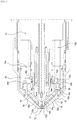
- The Applicant owns the patent of the plasma torch indicated in Patent Document 1. Further, the Applicant proposed a nozzle capable of realizing the effective cooling by cooling water by attaching it to the plasma torch (see Patent Document 2). The configurations of the plasma torch and the nozzle will be briefly described with reference to
FIG.5 . - In the
nozzle 52, the ejectinghole 52a for spraying plasma arc is formed in the center. Further, theannular passage 52b of the cooling water and a plurality ofindependent water passages 52c which communicate with theannular passage 52b are formed on thenozzle 52. By attaching thenozzle 52 with thetorch body 51, thewater passages nozzle 52 are formed in the plasma torch. In particular, thetorch body 51 has thewater supply port 54a which is connected to thewater passage 53a for supplying cooling water to thenozzle 51 and thewater drain port 54b which is connected to thewater passage 53b for draining the cooling water which passes through thenozzle 52. - Both of the
water supply port 54a and thewater drain port 54b or either thewater supply port 54a or thewater drain port 54b are configured as a groove connected to thewater passages water passages supply port 54a or thedrain port 54b is greater than the width on the circumference of a circle of theindependent water passage 52c formed in thenozzle 51 or the pitch on the circumference of the independent water passage. Thus, when thenozzle 52 is attached, one of theindependent water passages 52c formed in thenozzle 52 is communicated with thewater supply port 54a. Further, anotherindependent water passage 52c is communicated with thedrain port 54b. - A plurality of divided
pieces 55c for forming thewater passage 52c is formed on the outer periphery of thenozzle 52. Thenozzle 52 has theinner nozzle 55 whoseend surface 55a on the rear end side (the plasma torch side) is an energizing surface, theouter nozzle 56 for forming the cooling water passage formed between theinner nozzle 55 and theouter nozzle 56, and thesecondary airflow cap 57 for fastening thenozzle 52 to thetorch body 51. - When screwing the
secondary airflow cap 57 in attaching thenozzle 52 to thetorch body 51, thenozzle 52 is fixed when theend face 55a on the rear side (the plasma torch side) of theinner nozzle 55 becomes in contact with theenergizing surface 58a formed on thenozzle base 58 of the plasma torch. With the fixation of thenozzle 52, the annularcooling water passage 52b is formed on the position closer to the distal end side than the divided pieces (the ejecting hole side) between theinner nozzle 55 and theouter nozzle 56. Further, the plurality of independentcooling water passages 52c which communicate with thecooling water passage 52b are formed by the divided pieces. Thus, one of the independentcooling water passages 52c formed in thenozzle 52 communicates with thewater supply port 54a for supplying the cooling water and the cooling water provided to thenozzle 52 flows through theindependent water passage 52c to the annularcooling water passage 52b on the distal end side and thereafter the cooling water is discharged. Thus, thenozzle 52 can be cooled till the distal end portion of thenozzle 51 thereby preventing excessive heating due to the heat of the plasma arc. -
- Patent Document 1: Japanese Patent No.
3984584 - Patent Document 2: Japanese Laid-Open Patent Application No.
2005-118816 - Patent Document 3: International patent application No.
WO 03/089183 A1 -
Patent Document 3 discloses a plasma arc torch that provides a set of torch consumable components secured to a torch head, wherein a supply of cooling fluid flows coaxially through the torch to cool torch components and a supply of plasma gas an secondary gas flows through the torch to generate and stabilize a plasma stream for operations such a s cutting workpieces. The torch consumable components, in part, comprise an electrode and a tip that include a variety of configurations for improved cooling, electrical contact, and attachment to adjacent torch components. Further, a consumable cartridge is provided for ease of use and preplacement of the torch consumable components. Additionally, methods of operating the plasma arch torch at relatively high current levels are also provided. - In the configuration plasma torch as described above, when fastening the
secondary airflow cap 57 to thetorch body 51, a fastening force is transmitted via theouter nozzle 56 to theinner nozzle 55 thereby pressing theend surface 55a at the rear end side of theinner nozzle 55 on the energizingportion 58a of thenozzle base 58. Thestep portion 55b is formed on the wall portion at the ejectinghole 52a side of theinner nozzle 55 and thedistal portion 56a of theouter nozzle 56 is engaged in thestep portion 55b thereby transmitting the fastening force. In particular, in view of making thenozzle 52 as small as possible, it is impossible to increase the size of thestep portion 55b which is the portion that transmits the fastening force from theouter nozzle 56 to theinner nozzle 55, the processing becomes difficult. - Further, the
end surface 55a at the rear side of theinner nozzle 55 is in contact with the energizingportion 58a formed o thenozzle base 58 thereby making an electric connection. Thus, the reliable contact of theend surface 55a at the rear side of theinner nozzle 55 with theenergizing portion 58a of thenozzle base 58 is the highest priority. Thus, a gap is provided between theend surface 55c at the rear side of a divided piece formed in theinner nozzle 55 and the supply port 54 or thedrain port 54b formed in thetorch body 51. With this gap, an annular water passage is formed. By the annular water passage being formed, a part of the cooling water does not reach the tip of the nozzle and there is a possibility that the efficient cooling cannot be obtained. - Therefore, an object of the present invention is to provide a plasma torch which can effectively cool the nozzle till the ejecting hole of plasma arc and which has a stable energizing performance.
- In order to solve the above problem, the present invention provides a plasma torch according to claim 1.
- In the plasma torch of the present invention, the force for attaching the nozzle to the torch body is transmitted from the outer nozzle to the inner nozzle via the partitions which form independent water passages which are formed between the inner nozzle and the inner cap when the inner nozzle is fitted to the inner cap. That is, a force transmission portion is disposed at the torch body side of the nozzle. Thus, the size can be enlarged without changing the magnitude of the nozzle, which contributes to easiness of the processing.
- Further, the energization surface at the torch body side is formed on the end surface of the nozzle base in which the water supply port and the water drain port for the cooling water are formed. When fastening the inner cap to the torch body, the end surface is in contact with an end surface on the partition side of the inner nozzle, thereby obtaining electrification. Thus, a gap is not formed between the inner nozzle and the nozzle base, and all the cooling water supplied from the torch body to the nozzle flows from the independent water passages to the annular water passage, which contributes to effective cooling to the nozzle tip. In particular, since the end surface at the partition side of the inner nozzle and the end surface of the nozzle base are respectively configured as an electrification surface and the inner diameter sides of both of the end surfaces form a passage for the cooling water. Thus, it is possible to maintain a stable temperature irrespective of an elapsed time increase for plasma processing and to exhibit stable energization properties.
-
- [
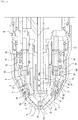
FIG. 1 ] a diagram illustrating the configuration of the main portion of a plasma torch according to the present embodiment - [
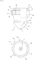
FIG. 2 ] a diagram illustrating the configuration of a nozzle base of the torch body - [
FIG. 3 ] a diagram illustrating the configuration of the outer nozzle - [
FIG. 4 ] a cross-sectional view illustrating the configuration of the inner nozzle - [
FIG. 5 ] a diagram illustrating the configuration of a conventional plasma torch - The configuration of a plasma torch according to the present invention will be explained below. The plasma torch according to the present invention is configured to be able to realize effective cooling by reliably providing cooling water to a tip side of the nozzle and to form a stable pilot arc between an electrode and the nozzle by reliably energizing the nozzle.
- The plasma torch according to the present invention has an inner nozzle which ejects plasma arc and an inner cap which is fastened to the torch body with the inner nozzle. When the inner nozzle is fitted to the inner cap, a plurality of independent water passages which communicate with an annular water passage are formed between the inner nozzle and the inner cap by the annular water passage and partitions. In particular, a fastening force for fastening the inner cap to the torch body is transmitted to the inner nozzle via the partitions and the inner nozzle becomes in contact with the torch body.
- The annular water passage is formed at the tip side (the ejecting hole side, hereinafter the same) of the nozzle. The independent water passages are formed at the rear end side (the torch body side when attaching the nozzle to the torch body, hereinafter the same).
- When the inner nozzle is fitted to the inner cap, the partitions perform the function of forming a plurality of independent water passages and the function of transmitting to the inner nozzle a fastening force by which the inner cap is fastened to the torch body. It is not limited whether the partitions should be formed either on the outer peripheral surface of the inner nozzle or on the inner peripheral surface of the inner cap.
- When the partitions are formed on the inner nozzle, the end surfaces at the rear end side of the partitions function as energizing surfaces which become in contact with the end surface of the nozzle base which has electric conductivity and which constitutes the torch body. When the partitions are formed on the inner cap, it is preferable to form a flange on the end portion at the rear side of the inner nozzle, which is in contact with the end surface at the rear end side of the partitions and to obtain electrical conductivity with the partitions being connected to the end surface of the nozzle base via the flange.
- The configuration for attaching the nozzle to the torch body is not limited. This configuration may be such that the inner cap itself is fastened to the torch body by screwing or such that a cap-shaped member which is disposed outside the inner cap is screwed to the torch body so that the nozzle is fastened to the torch body. In any case, it is sufficient that a fastening force for fastening the nozzle to the torch body is transmitted from the inner cap to the inner nozzle via the partitions so that the end surface of the inner nozzle becomes in contact with the end surface of the nozzle base.
- The water supply port and the water drain port are respectively connected to water passages formed on the torch body. When the nozzle is attached to the torch body, the independent water passages formed on the nozzle communicate with the water supply port and the water drain port formed on the torch body. At the same time, the end surface at the rear end side of the partitions which constitute independent water passages becomes in contact with the end surface of the nozzle base which has electric conductivity and which constitutes the torch body. The water supply port and the water drain port are formed on the nozzle base which constitutes torch body.
- The shapes of the water supply port and the water drain port are not limited, and these ports may be a hole with a circular shape, an elongated shape, a rectangular shape, or other shape. In the plasma torch according to the present invention, at least one of the water supply port and the water drain port is configured as a groove which extends in a plain which crosses the axes of the water passages. Namely, the groove is formed with the shape protruding from a water passage in a cross-section. In particular, it is preferable that the opening areas of the water supply port and the water drain port are larger than the cross-section areas of the water passages. Further, it is preferable that the water supply port and the water drain port are respectively formed with an arc shape of a circle with the axis of the torch body being the center of the circle.
- By configuring the water supply port or the water drain port as the above explained groove, when the nozzle is opposed to the water supply port and the water drain port, one of the independent water passages reliably communicate with the water supply port or the water drain port.
- When both of the water supply passage and the water drain passage are formed as grooves or either the water supply passage or the water drain passage is formed as a groove, it is preferable that the interval between the end portions of the grooves or the interval between the end portion and an end portion of the other port is larger than the width of independent water passage (length on a plane). By the configuration that the interval between the end portion and an end portion of the other port is larger than the width of independent water passage, when the nozzle is attached to the torch body, any one of independent water passages does not communicate with both of the water supply port and the water drain port, which enables an individual independent water passage to perform either the function for supplying the cooling water or the function for draining the cooling water.
- Next, the configuration of a plasma torch according to the present embodiment will be described with reference to figures. The plasma torch according to the present embodiment is constituted by the torch body B and the nozzle A, and the configuration of the nozzle A will be explained first.
- The plasma torch according to the present embodiment is configured to spray the secondary air flow along with the plasma arc. However, the presence of the secondary airflow is not limited in the present invention. That is, the plasma torch according to the present embodiment is configured to effectively cool the ejecting hole on the nozzle A for ejecting the plasma arc and it does not matter whether there is a secondary airflow or a higher airflow such as a tertiary airflow around the plasma arc which is ejected from the ejecting hole.
- The nozzle A is constituted of the
inner nozzle 2 in which the ejecting hole 1 is formed in the center for ejecting plasma arc and in which thewall portion 2a that forms the cylindrical wall is provided at a predetermined portion of the outer peripheral, and theinner cap 3 which has thefitting hole 3a in the center into which thewall portion 2a of theinner nozzle 2 is fitted. - The
secondary airflow cap 5 is disposed at the outer periphery side of theinner cap 3 via theinsulator 6 by which the secondary airflow passage 4 is formed between the outer circumferential surface of theinner cap 3 and thesecondary airflow cap 5. The ejectingport 5a is formed at the center of the tip of thesecondary airflow cap 5 for ejecting plasma arc and the secondary airflow. - When attaching the nozzle A to the torch body B, the
secondary airflow cap 5 can be used. However, in the present embodiment, by fastening theinner cap 3 to thenozzle base 14 which constitutes the torch body B, the nozzle A can be attached. - The ejecting hole 1 is formed at the center of the
inner nozzle 2. Further, thetapered portions surfaces wall portion 2a that forms the cylindrical wall is formed between thetapered portions base portion 2d which is parallel to the axis is formed continuously to the portion which has the maximum diameter of the taperedportion 2c. Further, thefitting portion 2e which fits to thenozzle base 14 of the torch body B is formed continuously to thebase portion 2d. - On the outer periphery of the
base portion 2d, a plurality of (eight in the present embodiment)partitions 2f are formed. By thepartitions 2f, thebase portion 2d is divided into a plurality of portions each of which constitutes an independent water passage. Thepartitions 2f have the function of transmitting a fastening force by theinner cap 3 when the nozzle A is attached to thenozzle base 14 of the torch body B. Thus, thefront end surface 2g and therear end surface 2h are formed to be perpendicular to the axis. - In particular, the
rear end surface 2h is formed not only on thepartitions 2f, but also on thebase portion 2d of theinner nozzle 2. Therefore, when the description that "therear end surface 2h of theinner nozzle 2" in the following explanation is intended to include the rear end surface of thebase portion 2d and the rear end surface of thepartitions 2f. Therear end surface 2h works as an energization surface which is energized by being in contact with theend surface 14a of thenozzle base 14 of the torch body B. - The
plasma chamber 23 is formed between theinner surface 2i of theinner nozzle 2 and the front surface of theelectrode 11 when the nozzle A is attached to the torch body B. On the outer periphery of thewall portion 2a and on the outer periphery of thefitting portion 2e, thegroove 2j for attaching an O-ring is provided respectively. - The
fitting hole 3a to which thewall portion 2a of theinner nozzle 2 fits is formed at the center of theinner cap 3. The taperedportion 3b (taperedsurface 3b) which is gradually widened is formed continuously to thefitting hole 3a. Further, thecylindrical base portion 3c is formed continuously to the portion which has the maximum diameter of the taperedportion 3b. The threadedportion 3d to which the torch body B is screwed is provided on the inner surface of thebase portion 3c. - The receiving
portion 3e for receiving thepartitions 2f formed on theinner nozzle 2 when theinner nozzle 2 fits to theinner cap 3 is formed on the inner surface of theinner cap 3. At the front end of the receivingportion 3e, thecontact surface 3f for being in contact with the front end surfaces 2g of thepartitions 2f is formed. The inner diameter of the receivingportion 3e is slightly greater than the outer diameter of thepartitions 2f of theinner nozzle 2. Further, the height of thecontact surface 3f is set such that thecontact surface 3f is in contact with thefront surfaces 2g of thepartitions 2f with a contact area sufficient for transmitting the fastening force when theinner cap 3 is fastened. Further, the length of the receivingportion 3e is slightly longer than the length of thepartitions 2f. - When the
inner nozzle 2 is fitted into the inner cap3 which is constituted as explained above, the annular water passage 8 through which the cooling water passes is formed between the taperedportion 2c and the taperedportion 3b. Further, by thefront end surface 2g of thepartitions 2f of theinner nozzle 2 being in contact with thecontact surface 3f of theinner cap 3, the independent water passages 9 which communicate with the annular water passage 8 are formed along thepartitions 2f. - When the
inner cap 3 and theinner nozzle 2 are combined as an integrated body, therear end surface 2h of thepartition 2f including the rear end surface of thebase portion 2d of theinner nozzle 2 is perpendicular to the axis of the nozzle A and slightly protrudes from the rear end surface of the receivingportion 3e of theinner cap 3. Thus, when the nozzle A is attached to the torch body B, therear end surface 2h of theinner nozzle 2 is reliably in contact with thenozzle base 14 of the torch body B. Further, therear end surface 2h is in contact with theend surface 14a of thenozzle base 14 thereby connecting one of the independent water passages 9 with thewater supply passage 20 and thewater drain passage 21 formed on thenozzle base 14. - In the nozzle A constituted as explained above, the cooling water supplied to one of the independent water passages 9 is introduced to the annular cooling water passage 8 from the independent water passage 9. At the annular cooling water passage 8, the cooling water is in contact with the tapered
portion 2c and cools it. Thereafter, the cooling water is drained from the independent water passage 9 disposed at the opposite side of the independent water passage 9 to which the cooling water is supplied. - Therefore, all the supplied cooling water reliably flows through the annular cooling water passage 8. With this process, the cooling water cools the tapered
portion 2c thereby substantially cooling the ejecting hole 1. Thus, the cooling effect for the plasma arc which passes through the ejecting hole 1 is enhanced and it is possible to make thinner the plasma arc. - Next, the configuration of the torch body B will be explained.
- The plasma torch of the present embodiment is configured such that the
electrode 11 can be attached to and detached from theelectrode base 12 provided at the center of the torch body B. On the outer periphery of theelectrode 11, the cylindrical centering stone 13 which has an insulating property is provided. The centering stone 13 has thehole 13a through which the plasma gas passes. Further, the outer periphery of the centering stone 13, the nozzle A is disposed. By fastening the inner cap which constitutes the nozzle A with thenozzle base 14 which constitutes the torch body B, therear end surface 2h of theinner nozzle 2 is in surface contact with theend surface 14a of thenozzle base 14, and the nozzle A and the centering stone 13 are fixed to the torch body B. - The
front end surface 14a of thenozzle base 14 is formed so as to be perpendicular to the axis of the torch body B. At the front side of thenozzle base 14, therecess portion 14b for receiving thefitting portion 2e of theinner nozzle 2 is formed. On the outer periphery of the front side of thenozzle base 14, the threadedportion 14c to which the threadedportion 3d of theinner cap 3 which constitutes the nozzle A is fastened by screwing. In thenozzle base 14, thehole 14d for fixing the codes connected to the power source (not shown) and thehole 14e for supplying the secondary airflow gas to the secondary airflow passage 4 are formed. - When the
fitting portion 2e of theinner nozzle 2 is fitted to therecess portion 14b of thenozzle base 14, theend surface 14a is in surface contact with therear end surface 2h of theinner nozzle 2. The O-ring disposed on the outer periphery of thefitting portion 2e is in contact with the inner peripheral surface of therecess portion 14b thereby preventing leakage of the cooling water. - In the torch body B, the cooling
tube 17 is provided on the axis and a supply tube (not shown) of the cooling water is connected to the coolingtube 17. By attaching theelectrode 11 to theelectrode base 12, theelectrode 11 is opposed to the open end side of the coolingtube 17 and thewater passage 18 which is continuous from the inner periphery to the outer periphery of the coolingtube 17 is formed. Thewater passage 18 is connected to thesupply passage 20 formed on theend surface 14a of thenozzle base 14 through thewater passage 19 formed on the torch body B and thenozzle base 14, and is further connected to the independent water passage 9 of the nozzle A from thewater supply passage 20. On theend surface 14a of thenozzle base 14, thewater drain passage 21 is formed at the position opposite to thewater supply passage 20 with respect to the axis. Thewater passage 22 is connected to thewater drain passage 21 and further a water drain tube (not shown) is connected to thewater passage 22. - As shown in
FIG. 2 , thewater supply passage 20 and thewater drain passage 21 are configured as grooves which are formed in arcs with the center of a circle being the axis of the torch body B with respect to the holes which constitute thewater passages water supply passage 20 and thewater drain passage 21 to be of an arc-like shape and it is sufficient for at least one of thewater supply passage 20 and thewater drain passage 21 to be of an arc-like shape. The length of the grooves which constitute thewater supply passage 20 and thedrain water passage 21 corresponds to the length of the independent water passages 9 (the length on therear end surface 2h). - The intervals between the ends of the groove constituting the
water supply passage 20 and the ends of the groove constituting thedrain water passage 21 are set to be larger than the width of the independent water passage 9. On the portion other than the portion between the ends of the grooves, thewater supply passage 20 and thewater drain passage 21 are formed. When the nozzle A is attached to thenozzle base 14, it is not preferable for an independent water passage 9 to be connected to both of thewater supply passage 20 and thewater drain passage 21. Thus, by setting the interval between thewater supply passage 20 and thedrain water passage 21 with reference to the width of the independent water passages 9, even if the nozzle A is attached to thenozzle base 14 in any situation, any one of the independent water passages 9 does not communicate with both of thewater supply passage 20 and thewater drain passage 21. - The procedure for constituting a plasma torch by attaching the nozzle A to the torch body B configured as above will be explained.
- Previously, the
inner nozzle 2 is fitted to theinner cap 3 thereby constituting the nozzle A. At this time, it is not necessary for thefront end surface 2g of thepartition 2f formed on theinner nozzle 2 to be in contact with thecontact surface 3f of theinner cap 3. Further, thenozzle base 14 is previously disposed in the torch body B and theelectrode 11 is attached to theelectrode base 12. Furthermore, the centering stone 13 is fitted is attached with theelectrode 11 being fitted to the centering stone 13. - The
fitting portion 2e of theinner nozzle 2 which constitutes the nozzle A is fitted to therecess portion 14b of thenozzle base 14 and the threadedportion 3d of theinner cap 3 is screwed to the threadedportion 14c of thenozzle base 14. With the screwing of theinner cap 3, thecontact portion 3f becomes in contact with thefront end surface 2g of thepartition 2f of theinner nozzle 2 and a fastening force produced at the time of fastening is transmitted to thepartition 2f (the inner nozzle 2). Then, therear end surface 2h of theinner nozzle 2 becomes in contact with theend surface 14a of thenozzle base 14. - By the fastening force produced by further fastening of the
inner cap 3, therear end surface 2h of theinner nozzle 2 is pressed on theend surface 14a of thenozzle base 14. With this operation, one of the independent water passages 9 is opposed to and communicates with thewater supply port 20 and another one of the independent water passages 9 is opposed to and communicates with thewater drain port 21. When the fastening of theinner cap 3 to thenozzle base 14 is ended, the nozzle A is attached to the torch body B. - When the cooling water is provided to the torch body B with the nozzle A being attached to the torch body B, the provided cooling water passes through the
water passage 18 formed inside the coolingtube 17 and cools theelectrode 11 with the provided cooling water being in contact with the inner surface of theelectrode 11. Thereafter, the provided cooling water passes through thewater passage 19 and reaches thewater supply passage 20. Thereafter, the provided cooling water is provided to the nozzle A. - The cooling water supplied to the nozzle A cools the nozzle A when passing through the annular water passage 8 from the independent water passage 9. Thereafter, the cooling water is drained to the
water drain passage 21 formed from the independent water passage 9 to thenozzle base 14. Thereafter, the cooling water is drained outside the torch body B by passing through thewater passage 22 and the water drain tube (not shown). - With the nozzle A and the torch B being cooled as stated above, the plasma gas is supplied to the
plasma chamber 23 formed around theelectrode 11 via the centering stone 13. Next, an electric discharge is formed by energizing thenozzle base 14, thereby forming a pilot arc. At this time, therear end surface 2h of theinner nozzle 2 is pressed on theend surface 14a of thenozzle base 14 and the cooling water passes in the very vicinity ofrear end surface 2h and theend surface 14a. Thus, therear end surface 2h and theend surface 14a are sufficiently cooled. Thus, a stable energization state can be obtained without considering a temperature rise with the energization, which contributes to forming a stable pilot arc. - The pilot arc formed between the
electrode 11 and theinner nozzle 2 is ejected from the ejecting hole 1 toward the material to be cut (not shown). By energizing between theelectrode 11 and the material to be cut in order to form a plasma arc (main arc) after the pilot arc reaches the material to be cut. By melting the material to be cut with this plasma arc and by eliminating the melted portion of the material to be cut, a groove which has a void portion in the thickness direction, which is made by the elimination of the melted portion. - Accordingly, while maintaining the energization between the
electrode 11 and the material to be cut to form a plasma arc, the plasma torch and the material to be cut are moved relatively to each other in a desired direction. Thus, a continuous groove on the material is formed, thereby cutting the material in a desired shape. - The plasma torch according to the present invention can be used for plasma cutting or welding.
-
- A
- nozzle
- B
- torch body
- 1
- ejecting hole
- 2
- inner nozzle
- 2a
- wall portion
- 2b, 2c
- tapered portion, the tapered surface
- 2d
- base portion
- 2e
- fitting portion
- 2f
- partition
- 2g
- front end surface
- 2h
- rear end surface
- 2i
- surface
- 2j
- groove
- 3
- inner cap
- 3a
- fitting hole
- 3b
- tapered portion, the tapered surface
- 3c
- base portion
- 3d
- threaded portion
- 3e
- receiving portion
- 3f
- contact surface
- 4
- secondary airflow passage
- 5
- secondary airflow cap
- 5a
- ejecting port
- 6
- insulator
- 8
- annular water passage
- 9
- independent water passage
- 11
- electrode
- 12
- electrode base
- 13
- centering Stone
- 13a
- hole
- 14
- nozzle base
- 14a
- end surface
- 14b
- recess portion
- 14c
- threaded portion
- 14d, 14e
- hole
- 17
- cooling tube
- 18, 19, 22
- water passage
- 20
- water supply passage
- 21
- water drain passage
- 23
- plasma chamber
Claims (1)
- A plasma torch, comprising:a nozzle (A) in which an ejecting hole (1) disposed in the center of the nozzle (A) for ejecting a plasma arc, an annular water passage (8) for cooling water, and a plurality of independent water passages (9) which communicate with the annular water passage (8) are formed; anda torch body (B) in which a plurality of water passages (19, 22) for circulating cooling water for cooling the nozzle (A) are formed,wherein the nozzle (A) includes:an inner nozzle (2) which ejects a plasma arc; andan inner cap (3) which is fastened to the torch body (B) with the inner nozzle (2),wherein partitions (2f) are formed on the outer peripheral surface of the inner nozzle (2), andwherein the inner nozzle (2) is configured for being fitted to the inner cap (3) such that the annular water passage (8) is formed between the inner nozzle (2) and the inner cap (3) and the plurality of independent water passages (9) are formed by the partitions (2f),wherein the torch body (B) includes:a water supply port (20) which is connected to one of the independent water passages (9) for supplying the cooling water to the nozzle (A);a water drain port (21) which is connected to one of the plurality of the independent water passages (9) for draining the cooling water which has passed through the nozzle (A); anda nozzle base (14) having an end surface (14a) which has electrical conductivity,wherein the water supply port and the water drain port (20, 21) are formed on said end surface (14a) of the nozzle base (14), each of the water supply port and the water drain port (20, 21) being configured as a groove connected to a respective one of the plurality of water passages (19, 22), wherein the groove extends on a plane which crosses the axes of said respective one of the plurality of water passages (19, 22), and an interval on a circumference of a circle between the ends of both grooves is greater than a pitch on the circumference of the circle of the partitions for forming the independent water passages, andwherein the nozzle (A) is configured for being fastened to the torch body (B) such that one of the independent water passages (9) formed in the nozzle (A) communicates with the water supply port (20) and another one of the independent water passages formed in the nozzle (A) communicates with the water drain port (21), and a rear end surface (2h) at a partition side of the inner nozzle (2) constituting the nozzle is able to be in contact with an end surface (14a) of the nozzle base (14) so as to obtain energization,characterized in that the partitions (2f) have a respective front end surface (2g) and a respective rear end surface (2h) which are perpendicular to the axis of the nozzle (A) and the partitions (2f) are configured to transmit a fastening force from the inner nozzle to the torch body when the nozzle (A) is attached to the nozzle base (14) of the torch body (B).
Applications Claiming Priority (2)
| Application Number | Priority Date | Filing Date | Title |
|---|---|---|---|
| JP2013170324A JP6161993B2 (en) | 2013-08-20 | 2013-08-20 | Plasma torch |
| PCT/JP2014/071578 WO2015025819A1 (en) | 2013-08-20 | 2014-08-18 | Plasma torch |
Publications (3)
| Publication Number | Publication Date |
|---|---|
| EP3038435A1 EP3038435A1 (en) | 2016-06-29 |
| EP3038435A4 EP3038435A4 (en) | 2017-06-07 |
| EP3038435B1 true EP3038435B1 (en) | 2020-12-02 |
Family
ID=52483594
Family Applications (1)
| Application Number | Title | Priority Date | Filing Date |
|---|---|---|---|
| EP14838671.7A Active EP3038435B1 (en) | 2013-08-20 | 2014-08-18 | Plasma torch |
Country Status (6)
| Country | Link |
|---|---|
| US (1) | US10595390B2 (en) |
| EP (1) | EP3038435B1 (en) |
| JP (1) | JP6161993B2 (en) |
| KR (1) | KR102249342B1 (en) |
| CN (1) | CN105474759B (en) |
| WO (1) | WO2015025819A1 (en) |
Families Citing this family (1)
| Publication number | Priority date | Publication date | Assignee | Title |
|---|---|---|---|---|
| EP3305037B1 (en) | 2015-06-08 | 2020-08-26 | Hypertherm, Inc | Cooling plasma torch nozzles and related systems |
Family Cites Families (13)
| Publication number | Priority date | Publication date | Assignee | Title |
|---|---|---|---|---|
| DE2263459C3 (en) | 1972-12-27 | 1978-11-02 | Basf Farben + Fasern Ag, 2000 Hamburg | Process for the production of opaque coatings or coatings with high hiding power by radiation curing of synthetic resin compositions and coating agents for carrying out the process |
| JPH02205270A (en) * | 1989-02-03 | 1990-08-15 | Hitachi Seiko Ltd | Plasma cutting and heating device |
| JPH03142077A (en) * | 1989-10-30 | 1991-06-17 | Brother Ind Ltd | Plasma cutting machine |
| JPH10180448A (en) * | 1996-12-26 | 1998-07-07 | Koike Sanso Kogyo Co Ltd | Plasma torch |
| US6096992A (en) * | 1999-01-29 | 2000-08-01 | The Esab Group, Inc. | Low current water injection nozzle and associated method |
| US6268583B1 (en) * | 1999-05-21 | 2001-07-31 | Komatsu Ltd. | Plasma torch of high cooling performance and components therefor |
| JP2001150142A (en) * | 1999-11-26 | 2001-06-05 | Koike Sanso Kogyo Co Ltd | Electrodes for plasma torch |
| WO2003089182A1 (en) * | 2002-04-19 | 2003-10-30 | Thermal Dynamics Corporation | Plasma arc torch electrode |
| JP2005118816A (en) | 2003-10-16 | 2005-05-12 | Koike Sanso Kogyo Co Ltd | Nozzle for plasma torch |
| JP3984584B2 (en) * | 2003-10-16 | 2007-10-03 | 小池酸素工業株式会社 | Plasma torch |
| JP2005329434A (en) * | 2004-05-20 | 2005-12-02 | Koike Sanso Kogyo Co Ltd | Electrode for plasma torch |
| JP5375763B2 (en) * | 2010-07-27 | 2013-12-25 | 三菱電機株式会社 | Plasma device and semiconductor thin film manufacturing method using the same |
| JP5841342B2 (en) * | 2011-03-17 | 2016-01-13 | 株式会社小松製作所 | Nozzle and plasma torch for plasma cutting device |
-
2013
- 2013-08-20 JP JP2013170324A patent/JP6161993B2/en active Active
-
2014
- 2014-08-18 WO PCT/JP2014/071578 patent/WO2015025819A1/en not_active Ceased
- 2014-08-18 EP EP14838671.7A patent/EP3038435B1/en active Active
- 2014-08-18 KR KR1020167006751A patent/KR102249342B1/en active Active
- 2014-08-18 CN CN201480045644.0A patent/CN105474759B/en active Active
- 2014-08-18 US US14/912,667 patent/US10595390B2/en active Active
Non-Patent Citations (1)
| Title |
|---|
| None * |
Also Published As
| Publication number | Publication date |
|---|---|
| KR102249342B1 (en) | 2021-05-07 |
| JP2015041411A (en) | 2015-03-02 |
| CN105474759A (en) | 2016-04-06 |
| EP3038435A4 (en) | 2017-06-07 |
| EP3038435A1 (en) | 2016-06-29 |
| US10595390B2 (en) | 2020-03-17 |
| JP6161993B2 (en) | 2017-07-12 |
| KR20160045088A (en) | 2016-04-26 |
| CN105474759B (en) | 2018-11-16 |
| US20160286637A1 (en) | 2016-09-29 |
| WO2015025819A1 (en) | 2015-02-26 |
Similar Documents
| Publication | Publication Date | Title |
|---|---|---|
| KR100646915B1 (en) | Nozzle for Plasma Torch | |
| EP3443818B1 (en) | Liquid cooled nozzle for a plasma arc cutting system and related operational methods | |
| EP2776202B1 (en) | Gmaw manual/robotic arc welding mig gun with connector for conductor tube | |
| EP2034805B1 (en) | Hybrid shield device for a plasma arc torch | |
| US10299363B2 (en) | Cooling plasma torch nozzles and related systems and methods | |
| JP6636249B2 (en) | Replacement parts unit for plasma torch | |
| US9572243B2 (en) | Air cooled plasma torch and components thereof | |
| US9572242B2 (en) | Air cooled plasma torch and components thereof | |
| KR101686540B1 (en) | Water Cooling Type Plasma Torch | |
| US10595390B2 (en) | Plasma torch | |
| US20210219412A1 (en) | Nozzles for liquid cooled plasma arc cutting torches with clocking-independent passages | |
| JPH10180448A (en) | Plasma torch | |
| KR20180007600A (en) | Plasma torch | |
| KR20180052861A (en) | Nozzle For Plasma Torch | |
| JP2005118817A (en) | Plasma torch |
Legal Events
| Date | Code | Title | Description |
|---|---|---|---|
| PUAI | Public reference made under article 153(3) epc to a published international application that has entered the european phase |
Free format text: ORIGINAL CODE: 0009012 |
|
| 17P | Request for examination filed |
Effective date: 20160309 |
|
| AK | Designated contracting states |
Kind code of ref document: A1 Designated state(s): AL AT BE BG CH CY CZ DE DK EE ES FI FR GB GR HR HU IE IS IT LI LT LU LV MC MK MT NL NO PL PT RO RS SE SI SK SM TR |
|
| AX | Request for extension of the european patent |
Extension state: BA ME |
|
| DAX | Request for extension of the european patent (deleted) | ||
| REG | Reference to a national code |
Ref country code: DE Ref legal event code: R079 Ref document number: 602014073012 Country of ref document: DE Free format text: PREVIOUS MAIN CLASS: H05H0001340000 Ipc: H05H0001280000 |
|
| A4 | Supplementary search report drawn up and despatched |
Effective date: 20170508 |
|
| RIC1 | Information provided on ipc code assigned before grant |
Ipc: H05H 1/34 20060101ALI20170428BHEP Ipc: H05H 1/28 20060101AFI20170428BHEP Ipc: B23K 10/00 20060101ALI20170428BHEP |
|
| GRAP | Despatch of communication of intention to grant a patent |
Free format text: ORIGINAL CODE: EPIDOSNIGR1 |
|
| STAA | Information on the status of an ep patent application or granted ep patent |
Free format text: STATUS: GRANT OF PATENT IS INTENDED |
|
| INTG | Intention to grant announced |
Effective date: 20200204 |
|
| GRAS | Grant fee paid |
Free format text: ORIGINAL CODE: EPIDOSNIGR3 |
|
| GRAJ | Information related to disapproval of communication of intention to grant by the applicant or resumption of examination proceedings by the epo deleted |
Free format text: ORIGINAL CODE: EPIDOSDIGR1 |
|
| GRAL | Information related to payment of fee for publishing/printing deleted |
Free format text: ORIGINAL CODE: EPIDOSDIGR3 |
|
| STAA | Information on the status of an ep patent application or granted ep patent |
Free format text: STATUS: REQUEST FOR EXAMINATION WAS MADE |
|
| GRAP | Despatch of communication of intention to grant a patent |
Free format text: ORIGINAL CODE: EPIDOSNIGR1 |
|
| STAA | Information on the status of an ep patent application or granted ep patent |
Free format text: STATUS: GRANT OF PATENT IS INTENDED |
|
| INTC | Intention to grant announced (deleted) | ||
| INTG | Intention to grant announced |
Effective date: 20200729 |
|
| GRAA | (expected) grant |
Free format text: ORIGINAL CODE: 0009210 |
|
| STAA | Information on the status of an ep patent application or granted ep patent |
Free format text: STATUS: THE PATENT HAS BEEN GRANTED |
|
| AK | Designated contracting states |
Kind code of ref document: B1 Designated state(s): AL AT BE BG CH CY CZ DE DK EE ES FI FR GB GR HR HU IE IS IT LI LT LU LV MC MK MT NL NO PL PT RO RS SE SI SK SM TR |
|
| REG | Reference to a national code |
Ref country code: GB Ref legal event code: FG4D |
|
| REG | Reference to a national code |
Ref country code: AT Ref legal event code: REF Ref document number: 1342396 Country of ref document: AT Kind code of ref document: T Effective date: 20201215 Ref country code: CH Ref legal event code: EP |
|
| REG | Reference to a national code |
Ref country code: DE Ref legal event code: R096 Ref document number: 602014073012 Country of ref document: DE |
|
| REG | Reference to a national code |
Ref country code: IE Ref legal event code: FG4D |
|
| PG25 | Lapsed in a contracting state [announced via postgrant information from national office to epo] |
Ref country code: RS Free format text: LAPSE BECAUSE OF FAILURE TO SUBMIT A TRANSLATION OF THE DESCRIPTION OR TO PAY THE FEE WITHIN THE PRESCRIBED TIME-LIMIT Effective date: 20201202 Ref country code: FI Free format text: LAPSE BECAUSE OF FAILURE TO SUBMIT A TRANSLATION OF THE DESCRIPTION OR TO PAY THE FEE WITHIN THE PRESCRIBED TIME-LIMIT Effective date: 20201202 Ref country code: NO Free format text: LAPSE BECAUSE OF FAILURE TO SUBMIT A TRANSLATION OF THE DESCRIPTION OR TO PAY THE FEE WITHIN THE PRESCRIBED TIME-LIMIT Effective date: 20210302 Ref country code: GR Free format text: LAPSE BECAUSE OF FAILURE TO SUBMIT A TRANSLATION OF THE DESCRIPTION OR TO PAY THE FEE WITHIN THE PRESCRIBED TIME-LIMIT Effective date: 20210303 |
|
| REG | Reference to a national code |
Ref country code: NL Ref legal event code: MP Effective date: 20201202 |
|
| REG | Reference to a national code |
Ref country code: AT Ref legal event code: MK05 Ref document number: 1342396 Country of ref document: AT Kind code of ref document: T Effective date: 20201202 |
|
| PG25 | Lapsed in a contracting state [announced via postgrant information from national office to epo] |
Ref country code: PL Free format text: LAPSE BECAUSE OF FAILURE TO SUBMIT A TRANSLATION OF THE DESCRIPTION OR TO PAY THE FEE WITHIN THE PRESCRIBED TIME-LIMIT Effective date: 20201202 Ref country code: SE Free format text: LAPSE BECAUSE OF FAILURE TO SUBMIT A TRANSLATION OF THE DESCRIPTION OR TO PAY THE FEE WITHIN THE PRESCRIBED TIME-LIMIT Effective date: 20201202 Ref country code: LV Free format text: LAPSE BECAUSE OF FAILURE TO SUBMIT A TRANSLATION OF THE DESCRIPTION OR TO PAY THE FEE WITHIN THE PRESCRIBED TIME-LIMIT Effective date: 20201202 Ref country code: BG Free format text: LAPSE BECAUSE OF FAILURE TO SUBMIT A TRANSLATION OF THE DESCRIPTION OR TO PAY THE FEE WITHIN THE PRESCRIBED TIME-LIMIT Effective date: 20210302 |
|
| PG25 | Lapsed in a contracting state [announced via postgrant information from national office to epo] |
Ref country code: NL Free format text: LAPSE BECAUSE OF FAILURE TO SUBMIT A TRANSLATION OF THE DESCRIPTION OR TO PAY THE FEE WITHIN THE PRESCRIBED TIME-LIMIT Effective date: 20201202 Ref country code: HR Free format text: LAPSE BECAUSE OF FAILURE TO SUBMIT A TRANSLATION OF THE DESCRIPTION OR TO PAY THE FEE WITHIN THE PRESCRIBED TIME-LIMIT Effective date: 20201202 |
|
| REG | Reference to a national code |
Ref country code: LT Ref legal event code: MG9D |
|
| PG25 | Lapsed in a contracting state [announced via postgrant information from national office to epo] |
Ref country code: SM Free format text: LAPSE BECAUSE OF FAILURE TO SUBMIT A TRANSLATION OF THE DESCRIPTION OR TO PAY THE FEE WITHIN THE PRESCRIBED TIME-LIMIT Effective date: 20201202 Ref country code: CZ Free format text: LAPSE BECAUSE OF FAILURE TO SUBMIT A TRANSLATION OF THE DESCRIPTION OR TO PAY THE FEE WITHIN THE PRESCRIBED TIME-LIMIT Effective date: 20201202 Ref country code: EE Free format text: LAPSE BECAUSE OF FAILURE TO SUBMIT A TRANSLATION OF THE DESCRIPTION OR TO PAY THE FEE WITHIN THE PRESCRIBED TIME-LIMIT Effective date: 20201202 Ref country code: PT Free format text: LAPSE BECAUSE OF FAILURE TO SUBMIT A TRANSLATION OF THE DESCRIPTION OR TO PAY THE FEE WITHIN THE PRESCRIBED TIME-LIMIT Effective date: 20210405 Ref country code: SK Free format text: LAPSE BECAUSE OF FAILURE TO SUBMIT A TRANSLATION OF THE DESCRIPTION OR TO PAY THE FEE WITHIN THE PRESCRIBED TIME-LIMIT Effective date: 20201202 Ref country code: RO Free format text: LAPSE BECAUSE OF FAILURE TO SUBMIT A TRANSLATION OF THE DESCRIPTION OR TO PAY THE FEE WITHIN THE PRESCRIBED TIME-LIMIT Effective date: 20201202 Ref country code: LT Free format text: LAPSE BECAUSE OF FAILURE TO SUBMIT A TRANSLATION OF THE DESCRIPTION OR TO PAY THE FEE WITHIN THE PRESCRIBED TIME-LIMIT Effective date: 20201202 |
|
| PG25 | Lapsed in a contracting state [announced via postgrant information from national office to epo] |
Ref country code: AT Free format text: LAPSE BECAUSE OF FAILURE TO SUBMIT A TRANSLATION OF THE DESCRIPTION OR TO PAY THE FEE WITHIN THE PRESCRIBED TIME-LIMIT Effective date: 20201202 |
|
| REG | Reference to a national code |
Ref country code: DE Ref legal event code: R097 Ref document number: 602014073012 Country of ref document: DE |
|
| PG25 | Lapsed in a contracting state [announced via postgrant information from national office to epo] |
Ref country code: IS Free format text: LAPSE BECAUSE OF FAILURE TO SUBMIT A TRANSLATION OF THE DESCRIPTION OR TO PAY THE FEE WITHIN THE PRESCRIBED TIME-LIMIT Effective date: 20210402 |
|
| PLBE | No opposition filed within time limit |
Free format text: ORIGINAL CODE: 0009261 |
|
| STAA | Information on the status of an ep patent application or granted ep patent |
Free format text: STATUS: NO OPPOSITION FILED WITHIN TIME LIMIT |
|
| PG25 | Lapsed in a contracting state [announced via postgrant information from national office to epo] |
Ref country code: AL Free format text: LAPSE BECAUSE OF FAILURE TO SUBMIT A TRANSLATION OF THE DESCRIPTION OR TO PAY THE FEE WITHIN THE PRESCRIBED TIME-LIMIT Effective date: 20201202 Ref country code: IT Free format text: LAPSE BECAUSE OF FAILURE TO SUBMIT A TRANSLATION OF THE DESCRIPTION OR TO PAY THE FEE WITHIN THE PRESCRIBED TIME-LIMIT Effective date: 20201202 |
|
| 26N | No opposition filed |
Effective date: 20210903 |
|
| PG25 | Lapsed in a contracting state [announced via postgrant information from national office to epo] |
Ref country code: ES Free format text: LAPSE BECAUSE OF FAILURE TO SUBMIT A TRANSLATION OF THE DESCRIPTION OR TO PAY THE FEE WITHIN THE PRESCRIBED TIME-LIMIT Effective date: 20201202 Ref country code: DK Free format text: LAPSE BECAUSE OF FAILURE TO SUBMIT A TRANSLATION OF THE DESCRIPTION OR TO PAY THE FEE WITHIN THE PRESCRIBED TIME-LIMIT Effective date: 20201202 Ref country code: SI Free format text: LAPSE BECAUSE OF FAILURE TO SUBMIT A TRANSLATION OF THE DESCRIPTION OR TO PAY THE FEE WITHIN THE PRESCRIBED TIME-LIMIT Effective date: 20201202 |
|
| REG | Reference to a national code |
Ref country code: CH Ref legal event code: PL |
|
| PG25 | Lapsed in a contracting state [announced via postgrant information from national office to epo] |
Ref country code: MC Free format text: LAPSE BECAUSE OF FAILURE TO SUBMIT A TRANSLATION OF THE DESCRIPTION OR TO PAY THE FEE WITHIN THE PRESCRIBED TIME-LIMIT Effective date: 20201202 |
|
| REG | Reference to a national code |
Ref country code: BE Ref legal event code: MM Effective date: 20210831 |
|
| GBPC | Gb: european patent ceased through non-payment of renewal fee |
Effective date: 20210818 |
|
| PG25 | Lapsed in a contracting state [announced via postgrant information from national office to epo] |
Ref country code: LI Free format text: LAPSE BECAUSE OF NON-PAYMENT OF DUE FEES Effective date: 20210831 Ref country code: CH Free format text: LAPSE BECAUSE OF NON-PAYMENT OF DUE FEES Effective date: 20210831 |
|
| PG25 | Lapsed in a contracting state [announced via postgrant information from national office to epo] |
Ref country code: IS Free format text: LAPSE BECAUSE OF FAILURE TO SUBMIT A TRANSLATION OF THE DESCRIPTION OR TO PAY THE FEE WITHIN THE PRESCRIBED TIME-LIMIT Effective date: 20210402 Ref country code: LU Free format text: LAPSE BECAUSE OF NON-PAYMENT OF DUE FEES Effective date: 20210818 |
|
| PG25 | Lapsed in a contracting state [announced via postgrant information from national office to epo] |
Ref country code: IE Free format text: LAPSE BECAUSE OF NON-PAYMENT OF DUE FEES Effective date: 20210818 Ref country code: GB Free format text: LAPSE BECAUSE OF NON-PAYMENT OF DUE FEES Effective date: 20210818 Ref country code: BE Free format text: LAPSE BECAUSE OF NON-PAYMENT OF DUE FEES Effective date: 20210831 |
|
| PG25 | Lapsed in a contracting state [announced via postgrant information from national office to epo] |
Ref country code: HU Free format text: LAPSE BECAUSE OF FAILURE TO SUBMIT A TRANSLATION OF THE DESCRIPTION OR TO PAY THE FEE WITHIN THE PRESCRIBED TIME-LIMIT; INVALID AB INITIO Effective date: 20140818 |
|
| P01 | Opt-out of the competence of the unified patent court (upc) registered |
Effective date: 20230505 |
|
| PG25 | Lapsed in a contracting state [announced via postgrant information from national office to epo] |
Ref country code: CY Free format text: LAPSE BECAUSE OF FAILURE TO SUBMIT A TRANSLATION OF THE DESCRIPTION OR TO PAY THE FEE WITHIN THE PRESCRIBED TIME-LIMIT Effective date: 20201202 |
|
| PG25 | Lapsed in a contracting state [announced via postgrant information from national office to epo] |
Ref country code: MK Free format text: LAPSE BECAUSE OF FAILURE TO SUBMIT A TRANSLATION OF THE DESCRIPTION OR TO PAY THE FEE WITHIN THE PRESCRIBED TIME-LIMIT Effective date: 20201202 |
|
| PG25 | Lapsed in a contracting state [announced via postgrant information from national office to epo] |
Ref country code: MT Free format text: LAPSE BECAUSE OF FAILURE TO SUBMIT A TRANSLATION OF THE DESCRIPTION OR TO PAY THE FEE WITHIN THE PRESCRIBED TIME-LIMIT Effective date: 20201202 |
|
| PGFP | Annual fee paid to national office [announced via postgrant information from national office to epo] |
Ref country code: DE Payment date: 20250922 Year of fee payment: 12 |
|
| PGFP | Annual fee paid to national office [announced via postgrant information from national office to epo] |
Ref country code: FR Payment date: 20250821 Year of fee payment: 12 |
|
| PG25 | Lapsed in a contracting state [announced via postgrant information from national office to epo] |
Ref country code: TR Free format text: LAPSE BECAUSE OF FAILURE TO SUBMIT A TRANSLATION OF THE DESCRIPTION OR TO PAY THE FEE WITHIN THE PRESCRIBED TIME-LIMIT Effective date: 20201202 |