EP3038302B1 - Grooming method and device for packet optical transport network - Google Patents
Grooming method and device for packet optical transport network Download PDFInfo
- Publication number
- EP3038302B1 EP3038302B1 EP14794779.0A EP14794779A EP3038302B1 EP 3038302 B1 EP3038302 B1 EP 3038302B1 EP 14794779 A EP14794779 A EP 14794779A EP 3038302 B1 EP3038302 B1 EP 3038302B1
- Authority
- EP
- European Patent Office
- Prior art keywords
- link
- layer virtual
- service
- otn layer
- virtual link
- Prior art date
- Legal status (The legal status is an assumption and is not a legal conclusion. Google has not performed a legal analysis and makes no representation as to the accuracy of the status listed.)
- Active
Links
Images



Classifications
-
- H—ELECTRICITY
- H04—ELECTRIC COMMUNICATION TECHNIQUE
- H04J—MULTIPLEX COMMUNICATION
- H04J14/00—Optical multiplex systems
- H04J14/02—Wavelength-division multiplex systems
- H04J14/0227—Operation, administration, maintenance or provisioning [OAMP] of WDM networks, e.g. media access, routing or wavelength allocation
- H04J14/0254—Optical medium access
- H04J14/0256—Optical medium access at the optical channel layer
-
- H—ELECTRICITY
- H04—ELECTRIC COMMUNICATION TECHNIQUE
- H04L—TRANSMISSION OF DIGITAL INFORMATION, e.g. TELEGRAPHIC COMMUNICATION
- H04L41/00—Arrangements for maintenance, administration or management of data switching networks, e.g. of packet switching networks
- H04L41/12—Discovery or management of network topologies
- H04L41/122—Discovery or management of network topologies of virtualised topologies, e.g. software-defined networks [SDN] or network function virtualisation [NFV]
-
- H—ELECTRICITY
- H04—ELECTRIC COMMUNICATION TECHNIQUE
- H04Q—SELECTING
- H04Q11/00—Selecting arrangements for multiplex systems
- H04Q11/0001—Selecting arrangements for multiplex systems using optical switching
- H04Q11/0003—Details
-
- H—ELECTRICITY
- H04—ELECTRIC COMMUNICATION TECHNIQUE
- H04Q—SELECTING
- H04Q11/00—Selecting arrangements for multiplex systems
- H04Q11/0001—Selecting arrangements for multiplex systems using optical switching
- H04Q11/0062—Network aspects
-
- H—ELECTRICITY
- H04—ELECTRIC COMMUNICATION TECHNIQUE
- H04Q—SELECTING
- H04Q11/00—Selecting arrangements for multiplex systems
- H04Q11/0001—Selecting arrangements for multiplex systems using optical switching
- H04Q11/0062—Network aspects
- H04Q2011/0088—Signalling aspects
-
- H—ELECTRICITY
- H04—ELECTRIC COMMUNICATION TECHNIQUE
- H04Q—SELECTING
- H04Q11/00—Selecting arrangements for multiplex systems
- H04Q11/0001—Selecting arrangements for multiplex systems using optical switching
- H04Q11/0062—Network aspects
- H04Q2011/009—Topology aspects
Definitions
- the present invention relates to the field of network technology, and particularly, to a grooming method and apparatus for a packet optical transport network.
- the Packet Optical Transport Network (POTN) technology is substantially a deep integration of the packet technology and the optical transport technology after the Packet Transport Network (PTN) technology. It not only has the packet processing capability of the PTN, but also integrates the enhanced line side bandwidth and transport distance of the Optical Transport Network (OTN) technology.
- OTN Optical Transport Network
- Main services borne by the network include: an ethernet service, a Synchronous Transport Module (STM) time-division service, an Oracle Database Unloader (ODU) service and an Optical Channel (OCH) service.
- the shortest path algorithm takes a distance between nodes as a weight, calculates a path with the minimum weight from a source node to a target node to complete the routing.
- the shortest path algorithm minimizes the price of distance and length, the power consumption problem is not considered.
- the power consumption of the path obtained by using the shortest path algorithm is not always the minimum, which goes against the energy saving.
- IP Internet protocol
- WDM wavelength division multiplexing
- the present application provides a grooming method for a packet optical transport network according to claim 1 and a grooming apparatus for a packet optical transport network according to claim 6.
- Also provided is a grooming method for a packet optical transport network which comprises steps:
- the step B comprises:
- the step B comprises:
- the step B comprises:
- the method further comprises:
- the method further comprises:
- a grooming apparatus for a packet optical transport network which comprises:
- the link establishment module is configured to:
- the link establishment module is configured to:
- the link establishment module is configured to:
- the grooming apparatus for the packet optical transport network further comprises a service sorting module, configured to:
- the topology set graph update module is further configured to:
- the wavelength link in the path is converted into the virtual link, the service path planning and wavelength allocation are finished with the power consumption as a weight between the nodes, so as to obtain a path with the minimum power consumption to implement the service routing, which is conducive to reducing the power consumption of services, thereby optimizing the power consumption of the entire network to the greatest extent.
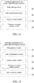
- FIG. 1 is a flowchart of a grooming method for a packet optical transport network according to the first embodiment of the present invention.
- the grooming method for the packet optical transport network mentioned in the embodiment includes the following steps:
- the topological structure of the POTN network has been known according to the practical applications, including the number of nodes and the node connectivity situation; there may be a plurality of physical links between the nodes in the topology of the POTN network, and each physical link has two optical fibers in opposite direction; and one optical fiber in the topology of the POTN network has a plurality of waves, namely wavelength links, and the number of waves in each optical fiber is not always equal.
- various services are sorted, and they are sorted according to categories of various services.
- the OCH services are arranged at first place, followed by the ODU services and STM services, and the ethernet services are arranged at last place.
- the OCH services are orderly arranged from large to small according to service capacities
- the ODU services and STM services are orderly arranged from large to small according to service capacities
- the ethernet services are orderly arranged from high to low according to priorities.
- an arranged order starting from the first service, one service is selected to perform the path planning, and the Dijkstra's algorithm is adopted to perform the path searching in the topology set graph.
- one duplicate graph may be firstly established according to the topology set graph, and the path searching is performed in the duplicate graph.
- the path planned in the topology set graph may include wavelength links and/or virtual links in the physical link.
- the weights of various links in the topology set graph are calculated. Since the capacity of the wavelength channel in the initial state is not occupied, the sides are all actual physical links at this point.
- the power consumption is taken as a weight between the nodes in the embodiment, the power consumption occupied by the physical link normally include the sum of power consumptions of an optical transmitter, optical amplifier and optical receiver in the link.
- the value of the N 0 may be decided based on a ratio of an actual length of the link to the intervals amplifiers are placed at.
- the weight W j of the jth segment of physical link is updated to a corresponding physical link in the topology set graph, and the initialization of the topology set graph is completed, wherein, j and N 0 are positive integers.
- step B when the path includes a wavelength link in a physical link, the wavelength link is removed, and a virtual link is established between a link source node and a link target node of the removed wavelength link; moreover, the virtual link represents a routing path that has been established in the physical topology, and if a new service connection request in the routing needs to use such segment of virtual link, as long as the capacity of the link allows, the routing in the link does not need any power consumption.
- the wavelength link included in the path planned in the embodiment is removed, and the virtual link is established between the nodes at the two ends of the removed wavelength link, thus during the service routing, the power consumptions of the physical link and the virtual link are taken as the weight, and the service routing is performed according to the principle of minimum power consumption, which is conducive to reducing the power consumption of the service routing.
- step C the capacities of various links in the path is updated; After the replanning of the path is completed, the service capacity is deducted from the capacity of the links (including the physical links and the virtual links) passed by the routing, and the remaining capacity of the links is obtained, to prepare for checking whether there is enough remaining capacity to meet the requirements of the service capacity when it is to plan a path of the next service in the following. Moreover, if the remaining capacity in the links cannot meet the requirements of the service capacity yet, in order to ensure smooth routing of the service, virtual links whose remaining capacity is less than the service capacity may be deleted. For example, when the service is the OCH service, all virtual links whose remaining capacity is less than the service capacity are deleted, and when the service is the ODU service or STM service, all packet layer virtual links whose remaining capacity is less than the service capacity are deleted.
- the newly established virtual link and the corresponding weight are added to the topology set graph for the path searching of the next service, and the planning of the current service is finished.
- step E whether the planning of all services is completed; if the planning of all services is completed, the flow ends; and if the planning of all services is not completed, then i+1, and it returns to the step A.
- the wavelength link in the path is converted into the virtual link, the service path planning and wavelength allocation are finished with the power consumption as a weight between the nodes, so as to obtain a path with the minimum power consumption to implement the service routing, which is conducive to reducing the power consumption of services, thereby optimizing the power consumption of the entire network to the greatest extent.
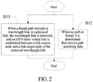
- FIG. 2 is a flowchart of a grooming method for a packet optical transport network according to the second embodiment of the present invention.
- the step B includes:
- wavelength links refer to one wave contained in the physical link, and these wavelength links are removed, that is, the wave is deleted from the corresponding physical link, and one OTN layer virtual link directly connecting a source node with a target node is established. If no path is found, it indicates that the service path establishment fails, and the path planning of the next service is performed.
- the wavelength link in the path of the OCH service is converted into the virtual link, the service path planning and wavelength allocation are finished with the power consumption as a weight between the nodes, so as to obtain a path with the minimum power consumption to implement the service routing, which is conducive to reducing the power consumption of the OCH service.
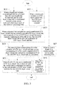
- FIG. 3 is a flowchart of a grooming method for a packet optical transport network according to the third embodiment of the present invention.
- the step B includes:
- the type of service is the ODU service or STM service
- the following cases are included:
- the old OTN layer virtual link is split into two or three OTN layer virtual sublinks, the sum of power consumptions P1 consumed by the OTN layer virtual sublinks is calculated, and the sum of power consumptions P2+P3 consumed by the newly established OTN layer virtual link and the old OTN layer virtual link is calculated, and it is to compare P1 with P2+P3.
- P1 ⁇ P2+P3 it indicates that the power consumptions of the virtual sublinks are smaller, based on the principle of minimum power consumption, the old OTN layer virtual link is selected, the old OTN layer virtual link is split into two or three OTN layer virtual links, services in the newly established virtual link are converted into the split virtual link in the meantime, and the capacity is updated, and then the newly established virtual link is deleted. If P1 > P2+P3, it indicates that the power consumption of the newly established OTN layer virtual link is smaller, and based on the principle of minimum power consumption, the newly established OTN layer virtual link is selected.
- the wavelength link in the path of the ODU service or STM service is converted into the virtual link, and the power consumptions between the newly established virtual link and the old virtual link are compared, the virtual link with the minimum power consumption is selected.
- the power consumption is taken as a weight between the nodes to complete the service path planning and wavelength allocation, so as to obtain a path with the minimum power consumption to implement the service routing, which is conducive to reducing the power consumption of the ODU service or STM service.
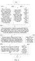
- FIG. 4 is a flowchart of a grooming method for a packet optical transport network according to the fourth embodiment of the present invention.
- the step B includes:
- the type of service is the ethernet service
- the following cases are included:
- the old OTN layer virtual link is split into two or three OTN layer virtual sublinks, the sum of power consumptions P1 consumed by the OTN layer virtual sublinks is calculated, and the sum of power consumptions P2+P3 consumed by the newly established OTN layer virtual link and the old OTN layer virtual link is calculated, and it is to compare P1 with P2+P3.
- P1 ⁇ P2+P3 it indicates that the power consumptions of the virtual sublinks are smaller, based on the principle of minimum power consumption, the old OTN layer virtual link is selected, and the old OTN layer virtual link is split into two or three OTN layer virtual links, services in the newly established virtual link are converted into the split virtual link in the meantime, and the capacity is updated, and then the newly established virtual link is deleted. If P1>P2+P3, it indicates that the power consumption of the newly established OTN layer virtual link is smaller, and based on the principle of minimum power consumption, the newly established OTN layer virtual link is selected.
- the wavelength link in the path of the ethernet service is converted into the virtual link, each link includes one OTN layer virtual link and one packet layer virtual link, and the power consumptions between the newly established OTN layer virtual link and the old OTN layer virtual link are compared, the virtual link with the minimum power consumption is selected, the power consumption is taken as a weight between the nodes to complete the service path planning and wavelength allocation, so as to obtain a path with the minimum power consumption to implement the service routing, which is conducive to reducing the power consumption of the ethernet service.
- the power consumption of the completed path may be calculated in the following ways.
- each link represents one pair of unidirectional optical fibers with same bandwidth and opposite direction
- each optical fiber has 4 waves, namely 4 wavelength links
- the maximum bandwidth of each wave is 40G
- the number of amplifiers in each optical fiber is 2
- the power consumption consumed by the transmitter is P T
- the power consumption consumed by the receiver is P R
- the power consumption consumed by the amplifier is P EDFA
- FIG. 5 is a data table of power consumptions of network devices in the embodiment of the present invention.
- FIG. 6 is a topology set graph of the POTN network in the embodiment of the present invention.
- FIG. 7 is an information table of services to be planned in the embodiment of the present invention.
- FIG. 8 is a table of actual physical links and virtual links passed by the services in the embodiment of the present invention.
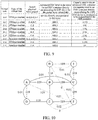
- FIG. 9 is an information table of virtual links in the embodiment of the present invention.
- FIG. 10 is a planned topology set graph in the embodiment of the present invention, including the wavelength links and the virtual links in the physical links.
- topology set graph is initialized, and the topology set graph shown in FIG. 6 is obtained, and values of the link weight are noted in various links in the figure.
- various services are sorted, and the information table of sorted services to be planned according to the requirement shown in FIG. 7 is obtained, here it is assumed that all services are unprotected, and the path searching methods in the case with protection and the case without protection are same.
- the path planning is performed for all services, firstly a service 1 is selected, the service 1 is an OCH service, the path searching is performed based on the Dijkstra algorithm in the set graph, the found paths are A-D, D-E and E-F, one wave in each of the three links is respectively occupied, thus three waves are left in each of the A-D, D-E and E-F at this point.
- One OTN layer virtual link A-F is established, and the physical links passed are the A-D, D-E and E-F. Since the OCH service is directly borne in the wave to be transmitted, the remaining capacity of the virtual link is 0, and new services cannot be contained any more.
- the newly established OTN layer virtual link A-F and the corresponding weight are added into the topology set graph, and the capacity of the virtual link is updated in the meantime, the power consumption consumed by the service 1 is calculated, and the planning of the service 1 is completed.
- the paths found based on the Dijkstra algorithm in the set graph are A-B and B-C. Since the capacity of the virtual link A-F is 0, the link is not selected.
- An OTN layer virtual link A-C is newly established, and the physical links passed are the A-B and B-C, three waves are left in each link, the newly established OTN layer virtual link A-C and the corresponding weight are added into the topology set graph, and the capacity of the virtual link is updated in the meantime.
- An advanced ODU in the wave is an ODU2, the remaining capacity of the advanced ODU2 is 0, the power consumption consumed by the service 2 is calculated, and the planning of the service 2 is completed.
- the found paths are A-C and C-I
- the A-C is an OTN layer virtual link and the C-I is an actual physical link.
- An OTN layer virtual link C-I is newly established, and the physical link passed is the C-I, the capacities of the virtual links A-C and C-I are updated.
- the ODU multiplexing is performed in the A-C, the ODU is expanded to an ODU3, two ODU2s are installed in the ODU3, an advanced ODU container in the virtual link C-I is an ODU2, the newly established virtual link C-I and the corresponding weight are added into the topology set graph, the power consumption consumed by the service 3 is calculated, and the planning of the service 3 is completed.
- the service path planning and wavelength allocation are also performed based on the above steps for other services.
- the ethernet service it is not only required to establish an OTN layer virtual link, but also required to establish an ODU pipeline namely a packet layer virtual link.
- the topology set graph shown in FIG. 10 is obtained, and a path is selected according to the planned topology set graph in the service routing, which is conducive to reducing the power consumption of services, thereby optimizing the power consumption of the entire network to the greatest extent.
- FIG. 11 is a schematic diagram of a structure of a grooming apparatus for a packet optical transport network according to the first embodiment of the present invention.
- the grooming apparatus for the packet optical transport network mentioned in the embodiment includes:
- the POTN network is mainly divided into three layers: a packet layer, an OTN layer and a WDM layer.
- the topology of the WDM layer is a physical topology of the entire network in essence, the OTN layer is a virtual topology composed of optical paths, the packet layer is a virtual topology composed of ODU pipelines. Since paths that may be found in the path searching of the embodiment include physical links and virtual links, the three topologies are assembled together to form a topology set graph.
- the topological structure of the POTN network has been known according to the practical applications, including the number of nodes and the node connectivity situation; there may be a plurality of physical links between the nodes in the topology of the POTN network, and each physical link has two optical fibers in opposite direction; and one optical fiber in the topology of the POTN network has a plurality of waves, namely wavelength links, and the number of waves in each optical fiber is not always equal.
- the virtual link represents a routing path that has been established in the physical topology, and if a new service connection request in the routing needs to use such segment of virtual link, as long as the capacity of the link allows, the routing in the link does not need any power consumption.
- the wavelength link included in the path planned in the embodiment is removed, and the virtual link is established between the nodes at the two ends of the removed wavelength link, thus during the service routing, the power consumptions of the physical link and the virtual link are taken as the weight, and the service routing is performed according to the principle of minimum power consumption, which is conducive to reducing the power consumption of the service routing.
- the service capacity is deducted from the capacity of the links (including the physical links and the virtual links) passed by the routing, and the remaining capacity of the links is obtained, to prepare for checking whether there is enough remaining capacity to meet the requirements of the service capacity when it is to plan a path of the next service in the following.
- virtual links whose remaining capacity is less than the service capacity may be deleted. For example, when the service is the OCH service, all virtual links whose remaining capacity is less than the service capacity are deleted, and when the service is the ODU service or STM service, all packet layer virtual links whose remaining capacity is less than the service capacity are deleted.
- the newly established virtual link and the corresponding weight are added to the topology set graph for the path searching of the next service, and the planning of the current service is finished.
- the wavelength link in the path is converted into the virtual link, the service path planning and wavelength allocation are finished with the power consumption as a weight between the nodes, so as to obtain a path with the minimum power consumption to implement the service routing, which is conducive to reducing the power consumption of services, thereby optimizing the power consumption of the entire network to the greatest extent.
- the link establishment module 20 is configured to:
- wavelength links refer to one wave contained in the physical link, and these wavelength links are removed, that is, the wave is deleted from the corresponding physical link, and one OTN layer virtual link directly connecting a source node with a target node is established. If no path is found, it indicates that the service path establishment fails, and the path planning of the next service is performed.
- the wavelength link in the path of the OCH service is converted into the virtual link, the service path planning and wavelength allocation are finished with the power consumption as a weight between the nodes, so as to obtain a path with the minimum power consumption to implement the service routing, which is conducive to reducing the power consumption of the OCH service.
- the link establishment module 20 is configured to:
- the type of service is the ODU service or STM service
- the following cases are included:
- the old OTN layer virtual link is split into two or three OTN layer virtual sublinks, the sum of power consumptions P1 consumed by the OTN layer virtual sublinks is calculated, and the sum of power consumptions P2+P3 consumed by the newly established OTN layer virtual link and the old OTN layer virtual link is calculated, and it is to compare P1 with P2+P3.
- P1 ⁇ P2+P3 it indicates that the power consumptions of the virtual sublinks are smaller, based on the principle of minimum power consumption, the old OTN layer virtual link is selected, the old OTN layer virtual link is split into two or three OTN layer virtual links, services in the newly established virtual link are converted into the split virtual link in the meantime, and the capacity is updated, and then the newly established virtual link is deleted. If P1 > P2+P3, it indicates that the power consumption of the newly established OTN layer virtual link is smaller, and based on the principle of minimum power consumption, the newly established OTN layer virtual link is selected.
- the wavelength link in the path of the ODU service or STM service is converted into the virtual link, and the power consumptions between the newly established virtual link and the old virtual link are compared, the virtual link with the minimum power consumption is selected, the power consumption is taken as a weight between the nodes to complete the service path planning and wavelength allocation, so as to obtain a path with the minimum power consumption to implement the service routing, which is conducive to reducing the power consumption of the ODU service or STM service.
- the link establishment module 20 is configured to:
- the type of service is the ethernet service
- the following cases are included:
- the old OTN layer virtual link is split into two or three OTN layer virtual sublinks, the sum of power consumptions P1 consumed by the OTN layer virtual sublinks is calculated, and the sum of power consumptions P2+P3 consumed by the newly established OTN layer virtual link and the old OTN layer virtual link is calculated, and it is to compare P1 with P2+P3.
- P1 ⁇ P2+P3 it indicates that the power consumptions of the virtual sublinks are smaller, based on the principle of minimum power consumption, the old OTN layer virtual link is selected, the old OTN layer virtual link is split into two or three OTN layer virtual links, services in the newly established virtual link are converted into the split virtual link in the meantime, and the capacity is updated, and then the newly established virtual link is deleted. If P1 > P2+P3, it indicates that the power consumption of the newly established OTN layer virtual link is smaller, and based on the principle of minimum power consumption, the newly established OTN layer virtual link is selected.
- the wavelength link in the path of the ethernet service is converted into the virtual link, each link includes one OTN layer virtual link and one packet layer virtual link, and the power consumptions between the newly established OTN layer virtual link and the old OTN layer virtual link are compared, and the virtual link with the minimum power consumption is selected, the power consumption is taken as a weight between the nodes to complete the service path planning and wavelength allocation, so as to obtain a path with the minimum power consumption to implement the service routing, which is conducive to reducing the power consumption of the ethernet service.
- FIG. 12 is a schematic diagram of a structure of a grooming apparatus for a packet optical transport network according to the second embodiment of the present invention.
- a service sorting module 50 is added, and it is configured to:
- various services are sorted, and they are sorted according to categories of various services, the OCH services are arranged at first place, followed by the ODU services and STM services, and the ethernet services are arranged at last place.
- the OCH services are orderly arranged from large to small according to service capacities
- the ODU services and STM services are orderly arranged from large to small according to service capacities
- the ethernet services are orderly arranged from high to low according to priorities.
- one service is selected to perform path planning, and the Dijkstra's algorithm is adopted to perform the path searching in the topology set graph.
- one duplicate graph may be firstly established according to the topology set graph, and the path searching is performed in the duplicate graph.
- topology set graph update module 40 is also configured to:
- the path planned in the topology set graph may include wavelength links and/or virtual links in the physical link.
- weights of various links in the topology set graph are calculated. Since the capacity of the wavelength channel in the initial state is not occupied, the sides are all actual physical links at this point.
- the value of the N 0 may be decided based on a ratio of an actual length of the link to the intervals amplifiers are placed at.
- the weight W j of the jth segment of physical link is updated to a corresponding physical link in the topology set graph, and the initialization of the topology set graph is completed.
- the power consumption of the completed path may be calculated in the following ways.
- the wavelength link in the path is converted into the virtual link, the service path planning and wavelength allocation are finished with the power consumption as a weight between the nodes, so as to obtain a path with the minimum power consumption to implement the service routing, which is conducive to reducing the power consumption of services, thereby optimizing the power consumption of the entire network to the greatest extent.
Landscapes
- Engineering & Computer Science (AREA)
- Computer Networks & Wireless Communication (AREA)
- Signal Processing (AREA)
- Data Exchanges In Wide-Area Networks (AREA)
- Optical Communication System (AREA)
Description
- The present invention relates to the field of network technology, and particularly, to a grooming method and apparatus for a packet optical transport network.
- The Packet Optical Transport Network (POTN) technology is substantially a deep integration of the packet technology and the optical transport technology after the Packet Transport Network (PTN) technology. It not only has the packet processing capability of the PTN, but also integrates the enhanced line side bandwidth and transport distance of the Optical Transport Network (OTN) technology. In the metropolitan area network of the operators in our country, the POTN will be first applied in the core and the convergence layer of the metropolitan area network, and with the promotion of the capacity requirements of the access layer, it extends to the access layer step by step. Main services borne by the network include: an ethernet service, a Synchronous Transport Module (STM) time-division service, an Oracle Database Unloader (ODU) service and an Optical Channel (OCH) service.
- In the traditional network routing algorithm, generally the shortest path algorithm is adopted to make a routing selection. The shortest path algorithm takes a distance between nodes as a weight, calculates a path with the minimum weight from a source node to a target node to complete the routing. Though the shortest path algorithm minimizes the price of distance and length, the power consumption problem is not considered. Thus the power consumption of the path obtained by using the shortest path algorithm is not always the minimum, which goes against the energy saving.
- The scientific publications "Traffic Grooming in Green Optical Networks" (by M. M HASAN et Al., in 2013 IEEE INTERNATIONAL CONFERENCE ON COMMUNICATIONS), and "Energy-Aware Path Selection for Scheduled Lightpath in IP-over-WDM Networks" (by SONG YANG et Al., in COMMUNICATIONS AND VEHICULAR TECHNOLOGY IN THE BENELUX (SCVT), 2011 18TH IEEE SYMPOSIUM ON, IEEE, 2011-11-22, p.1-6), disclose traffic grooming in optical network for energy consumption.
-
CN 102970225 A discloses Internet protocol (IP) over wavelength division multiplexing (WDM) network energy-aware routing method based on multipriority business. - The present application provides a grooming method for a packet optical transport network according to
claim 1 and a grooming apparatus for a packet optical transport network according toclaim 6. - Also provided is a grooming method for a packet optical transport network, which comprises steps:
- step A, according to an arrangement order of various services, planning a path from a service source node to a service target node in an ith service in a topology set graph; wherein an initial value of i is 1;
- step B, when the path comprises a wavelength link in a physical link, removing the wavelength link, and establishing a virtual link between a link source node and a link target node of the removed wavelength link;
- step C, updating capacities of various links in the path;
- step D, calculating a weight of a newly established virtual link, and adding the newly established virtual link and the corresponding weight to the topology set graph; and
- step E, if i+1, returning to the step A, until all services are finished, wherein, i is a positive integer.
- Preferably, when the ith service is an OCH service, the step B comprises:
- step B11, when a found path comprises a wavelength link in a physical link, removing the wavelength link, and establishing an OTN layer virtual link between a link source node and a link target node of the removed wavelength link; and
- step B12, when no path is found, determining that service path searching fails, and executing the step E.
- Preferably, when the ith service is an ODU service or an STM service, the step B comprises:
- step B21, when a found path comprises a wavelength link in a physical link, removing the wavelength link, and establishing an OTN layer virtual link between a link source node and a link target node of the removed wavelength link;
- step B22, when a found path comprises an OTN layer virtual link, retaining the OTN layer virtual link;
- step B23, when a physical link comprised in a newly established OTN layer virtual link has existed in an old OTN layer virtual link, and a capacity of the old OTN layer virtual link meets capacity requirements of the ith service, splitting the old OTN layer virtual link into a plurality of OTN layer virtual sublinks;
- step B24, calculating the sum of power consumptions P1 of the plurality of OTN layer virtual sublinks, power consumption P2 of the newly established OTN layer virtual link, and power consumption P3 of the old OTN layer virtual link;
- step B25, when P1≤P2+P3, removing the newly established OTN layer virtual link, and establishing a virtual link according to the plurality of split OTN layer virtual sublinks for the old OTN layer virtual link;
- step B26, when P1>P2+P3, retaining the newly established OTN layer virtual link; and
- step B27, when no path is found, determining that service path searching fails, and executing the step E.
- Preferably, when the ith service is an ethernet service, the step B comprises:
- step B31, when a found path comprises a wavelength link in a physical link, removing the wavelength link, and respectively establishing an OTN layer virtual link and a packet layer virtual link between a link source node and a link target node of the removed wavelength link;
- step B32, when a found path comprises a packet layer virtual link, establishing a packet layer virtual link between a link source node and a link target node of the OTN layer virtual link;
- step B33, when a found path comprises a packet layer virtual link, retaining the packet layer virtual link;
- step B34, when a physical link comprised in a newly established OTN layer virtual link has existed in an old OTN layer virtual link, and a capacity of the old OTN layer virtual link meets capacity requirements of the ith service, splitting the old OTN layer virtual link into a plurality of OTN layer virtual sublinks;
- step B35, calculating the sum of power consumptions P1 of the plurality of OTN layer virtual sublinks, power consumption P2 of the newly established OTN layer virtual link, and power consumption P3 of the old OTN layer virtual link;
- step B36, when P1≤P2+P3, removing the newly established OTN layer virtual link, and establishing the virtual link according to the plurality of split OTN layer virtual sublinks for the old OTN layer virtual link;
- step B37, when P1 >P2+P3, retaining the newly established OTN layer virtual link; and
- step B38, when no path is found, determining that service path searching fails, and executing the step E.
- Preferably, before the step A, the method further comprises:
- sorting categories of various services, and arranging OCH services at first place, ODU services and STM services at second place, and ethernet services at last place; and
- orderly arranging the OCH services from large to small according to service capacities, orderly arranging the ODU services and STM services from large to small according to service capacities, and orderly arranging the ethernet services from high to low according to priorities.
- Preferably, before the step A, the method further comprises:
- calculating a weight Wj=PT+N0×PA+PR of a jth segment of physical link in the topology set graph; wherein PT is power consumption of an optical transmitter in the jth segment of physical link, PA is power consumption of an optical amplifier in the jth segment of physical link, PR is power consumption of an optical receiver in the jth segment of physical link, and No is the number of optical amplifiers in the jth segment of physical link; and
- updating the weight Wj of the jth segment of physical link to a corresponding physical link in the topology set graph, wherein, j and No are positive integers.
- Also provided is a grooming apparatus for a packet optical transport network, which comprises:
- a path planning module, configured to: according to an arrangement order of various services, plan a path from a service source node to a service target node in an ith service in a topology set graph; wherein an initial value of i is 1;
- a link establishment module, configured to: when the path comprises a wavelength link in a physical link, remove the wavelength link, and establish a virtual link between a link source node and a link target node of the removed wavelength link;
- a capacity update module, configured to: update capacities of various links in the path; and
- a topology set graph update module, configured to: calculate a weight of a newly established virtual link, and add the newly established virtual link and the corresponding weight to the topology set graph, wherein, i is a positive integer.
- Preferably, when the ith service is an OCH service, the link establishment module is configured to:
- when a found path comprises a wavelength link in a physical link, remove the wavelength link, and establish an optical transport network OTN layer virtual link between a link source node and a link target node of the removed wavelength link; and
- when no path is found, determine that service path searching fails.
- Preferably, when the ith service is an ODU service or an STM service, the link establishment module is configured to:
- when a found path comprises a wavelength link in a physical link, remove the wavelength link, and establish an OTN layer virtual link between a link source node and a link target node of the removed wavelength link;
- when a found path comprises an OTN layer virtual link, retain the OTN layer virtual link;
- when a physical link comprised in a newly established OTN layer virtual link has existed in an old OTN layer virtual link, and a capacity of the old OTN layer virtual link meets capacity requirements of the ith service, split the old OTN layer virtual link into a plurality of OTN layer virtual sublinks;
- calculate the sum of power consumptions P1 of the plurality of OTN layer virtual sublinks, power consumption P2 of the newly established OTN layer virtual link, and power consumption P3 of the old OTN layer virtual link;
- when P1≤P2+P3, remove the newly established OTN layer virtual link, and establish the virtual link according to the plurality of split OTN layer virtual sublinks for the old OTN layer virtual link;
- when P1 >P2+P3, retain the newly established OTN layer virtual link; and
- when no path is found, determine that service path searching fails.
- Preferably, when the ith service is an ethernet service, the link establishment module is configured to:
- when a found path comprises a wavelength link in a physical link, remove the wavelength link, and respectively establish an OTN layer virtual link and a packet layer virtual link between a link source node and a link target node of the removed wavelength link;
- when a found path comprises a packet layer virtual link, establish a packet layer virtual link between a link source node and a link target node of the OTN layer virtual link;
- when a found path comprises a packet layer virtual link, retain the packet layer virtual link;
- when a physical link comprised in a newly established OTN layer virtual link has existed in an old OTN layer virtual link, and a capacity of the old OTN layer virtual link meets capacity requirements of the ith service, split the old OTN layer virtual link into a plurality of OTN layer virtual sublinks;
- calculate the sum of power consumptions P1 of the plurality of OTN layer virtual sublinks, power consumption P2 of the newly established OTN layer virtual link, and power consumption P3 of the old OTN layer virtual link;
- when P1≤P2+P3, remove the newly established OTN layer virtual link, and establish the virtual link according to the plurality of split OTN layer virtual sublinks for the old OTN layer virtual link;
- when P1 >P2+P3, retain the newly established OTN layer virtual link; and
- when no path is found, determine that service path searching fails.
- Preferably, the grooming apparatus for the packet optical transport network further comprises a service sorting module, configured to:
- sort categories of various services, and arrange OCH services at first place, ODU services and STM services at second place, and ethernet services at last place; and
- orderly arrange the OCH services from large to small according to service capacities, orderly arrange the ODU services and STM services from large to small according to service capacities, and orderly arrange the ethernet services from high to low according to priorities.
- Preferably, the topology set graph update module is further configured to:
- calculate a weight Wj=PT+N0 × PA+PR of a jth segment of physical link in the topology set graph; wherein PT is power consumption of an optical transmitter in the jth segment of physical link, PA is power consumption of an optical amplifier in the jth segment of physical link, PR is power consumption of an optical receiver in the jth segment of physical link, and N0 is the number of optical amplifiers in the jth segment of physical link; and
- update the weight Wj of the jth segment of physical link to a corresponding physical link in the topology set graph, wherein, j and N0 are positive integers.
- In the embodiments of the present invention, the wavelength link in the path is converted into the virtual link, the service path planning and wavelength allocation are finished with the power consumption as a weight between the nodes, so as to obtain a path with the minimum power consumption to implement the service routing, which is conducive to reducing the power consumption of services, thereby optimizing the power consumption of the entire network to the greatest extent.
-
-
FIG. 1 is a flowchart of a grooming method for a packet optical transport network according to the first embodiment of the present invention; -
FIG. 2 is a flowchart of a grooming method for a packet optical transport network according to the second embodiment of the present invention; -
FIG. 3 is a flowchart of a grooming method for a packet optical transport network according to the third embodiment of the present invention; -
FIG. 4 is a flowchart of a grooming method for a packet optical transport network according to the fourth embodiment of the present invention; -
FIG. 5 is a data table of power consumptions of network devices in the embodiment of the present invention; -
FIG. 6 is a topology set graph of a POTN network in the embodiment of the present invention; -
FIG. 7 is an information table of services to be planned in the embodiment of the present invention; -
FIG. 8 is a table of actual physical links and virtual links passed by the services in the embodiment of the present invention; -
FIG. 9 is an information table of virtual links in the embodiment of the present invention; -
FIG. 10 is a planned topology set graph in the embodiment of the present invention; -
FIG. 11 is a schematic diagram of a structure of a grooming apparatus for a packet optical transport network according to the first embodiment of the present invention; -
FIG. 12 is a schematic diagram of a structure of a grooming apparatus for a packet optical transport network according to the second embodiment of the present invention; - The implementation of the object, function characteristics and advantages of the embodiments of the present invention will be correspondingly described in combination with the embodiments and with reference to the accompanying drawings.
- It should be understood that, the specific embodiments described here are only used to explain the present invention, which is not used to limit the present invention. It should be noted that the embodiments in the present invention and the characteristics in the embodiments can be arbitrarily combined with each other in the case of no conflict.
- As shown in
FIG. 1, FIG. 1 is a flowchart of a grooming method for a packet optical transport network according to the first embodiment of the present invention. The grooming method for the packet optical transport network mentioned in the embodiment includes the following steps: - in step A, according to an arrangement order of various services, a path from a service source node to a service target node in an ith service is planned in a topology set graph; and an initial value of i is 1;
- in the embodiment, the POTN network is mainly divided into three layers: a packet layer, an OTN layer and a Wavelength Division Multiplexing (WDM) layer. The topology of the WDM layer is a physical topology of the entire network in essence, the OTN layer is a virtual topology composed of optical paths and the packet layer is a virtual topology composed of Oracle Database Unloader (ODU) pipelines. Since paths that may be found in the path searching in the embodiment include physical links and virtual links, the three topologies are assembled together to form a topology set graph.
- When the POTN network is planned, the following condition is taken as a limitation: the topological structure of the POTN network has been known according to the practical applications, including the number of nodes and the node connectivity situation; there may be a plurality of physical links between the nodes in the topology of the POTN network, and each physical link has two optical fibers in opposite direction; and one optical fiber in the topology of the POTN network has a plurality of waves, namely wavelength links, and the number of waves in each optical fiber is not always equal.
- Before the path is planned, various services are sorted, and they are sorted according to categories of various services. The OCH services are arranged at first place, followed by the ODU services and STM services, and the ethernet services are arranged at last place. The OCH services are orderly arranged from large to small according to service capacities, the ODU services and STM services are orderly arranged from large to small according to service capacities, and the ethernet services are orderly arranged from high to low according to priorities. According to an arranged order, starting from the first service, one service is selected to perform the path planning, and the Dijkstra's algorithm is adopted to perform the path searching in the topology set graph. In addition, one duplicate graph may be firstly established according to the topology set graph, and the path searching is performed in the duplicate graph.
- The path planned in the topology set graph may include wavelength links and/or virtual links in the physical link. In the stage of network initialization, the weights of various links in the topology set graph are calculated. Since the capacity of the wavelength channel in the initial state is not occupied, the sides are all actual physical links at this point. The power consumption is taken as a weight between the nodes in the embodiment, the power consumption occupied by the physical link normally include the sum of power consumptions of an optical transmitter, optical amplifier and optical receiver in the link. The weight Wj = PT +N0×PA+PR of a jth segment of physical link in the topology set graph is calculated, wherein PT is the power consumption of the optical transmitter in the jth segment of physical link, PA is the power consumption of the optical amplifier in the jth segment of physical link, PR is the power consumption of the optical receiver in the jth segment of physical link, and N0 is the number of optical amplifiers in the jth segment of physical link. Here the value of the N0 may be decided based on a ratio of an actual length of the link to the intervals amplifiers are placed at. The weight Wj of the jth segment of physical link is updated to a corresponding physical link in the topology set graph, and the initialization of the topology set graph is completed, wherein, j and N0 are positive integers.
- In step B, when the path includes a wavelength link in a physical link, the wavelength link is removed, and a virtual link is established between a link source node and a link target node of the removed wavelength link;
moreover, the virtual link represents a routing path that has been established in the physical topology, and if a new service connection request in the routing needs to use such segment of virtual link, as long as the capacity of the link allows, the routing in the link does not need any power consumption. Therefore, the wavelength link included in the path planned in the embodiment is removed, and the virtual link is established between the nodes at the two ends of the removed wavelength link, thus during the service routing, the power consumptions of the physical link and the virtual link are taken as the weight, and the service routing is performed according to the principle of minimum power consumption, which is conducive to reducing the power consumption of the service routing. - In step C, the capacities of various links in the path is updated;
After the replanning of the path is completed, the service capacity is deducted from the capacity of the links (including the physical links and the virtual links) passed by the routing, and the remaining capacity of the links is obtained, to prepare for checking whether there is enough remaining capacity to meet the requirements of the service capacity when it is to plan a path of the next service in the following. Moreover, if the remaining capacity in the links cannot meet the requirements of the service capacity yet, in order to ensure smooth routing of the service, virtual links whose remaining capacity is less than the service capacity may be deleted. For example, when the service is the OCH service, all virtual links whose remaining capacity is less than the service capacity are deleted, and when the service is the ODU service or STM service, all packet layer virtual links whose remaining capacity is less than the service capacity are deleted. - In step D, a weight of the newly established virtual link is calculated, and the newly established virtual link and the corresponding weight are added to the topology set graph;
in the embodiment, when the capacity of the virtual link allows, the routing in the link does not need any power consumption, thus the weight of the virtual link may be represented as: a weight Wv1=0.01 of the OTN layer virtual link and a weight Wv2=0 of the packet layer virtual link. The newly established virtual link and the corresponding weight are added to the topology set graph for the path searching of the next service, and the planning of the current service is finished. - In step E, whether the planning of all services is completed; if the planning of all services is completed, the flow ends; and if the planning of all services is not completed, then i+1, and it returns to the step A.
- In the embodiment, the wavelength link in the path is converted into the virtual link, the service path planning and wavelength allocation are finished with the power consumption as a weight between the nodes, so as to obtain a path with the minimum power consumption to implement the service routing, which is conducive to reducing the power consumption of services, thereby optimizing the power consumption of the entire network to the greatest extent.
- As shown in
FIG. 2, FIG. 2 is a flowchart of a grooming method for a packet optical transport network according to the second embodiment of the present invention. In the embodiment, based on the embodiment shown inFIG. 1 , when the ith service is the OCH service, the step B includes: - step B11, when a found path includes a wavelength link in a physical link, removing the wavelength link, and establishing an OTN layer virtual link between a link source node and a link target node of the removed wavelength link;
- step B12, when no path is found, determining that the service path searching fails, and executing the step E.
- In the embodiment, when the type of service is the OCH service, since the OCH service is arranged at the first place during the sorting, all found paths are basically wavelength links at this point. The wavelength links refer to one wave contained in the physical link, and these wavelength links are removed, that is, the wave is deleted from the corresponding physical link, and one OTN layer virtual link directly connecting a source node with a target node is established. If no path is found, it indicates that the service path establishment fails, and the path planning of the next service is performed.
- In the embodiment, the wavelength link in the path of the OCH service is converted into the virtual link, the service path planning and wavelength allocation are finished with the power consumption as a weight between the nodes, so as to obtain a path with the minimum power consumption to implement the service routing, which is conducive to reducing the power consumption of the OCH service.
- As shown in
FIG. 3, FIG. 3 is a flowchart of a grooming method for a packet optical transport network according to the third embodiment of the present invention. In the embodiment, based on the embodiment shown inFIG. 1 , when the ith service is the ODU service or STM service, the step B includes: - step B21, when a found path includes a wavelength link in a physical link, removing the wavelength link, and establishing an OTN layer virtual link between a link source node and a link target node of the removed wavelength link;
- step B22, when a found path includes an OTN layer virtual link, retaining the OTN layer virtual link;
- step B23, when a physical link included in a newly established OTN layer virtual link has existed in an old OTN layer virtual link, and a capacity of the old OTN layer virtual link meets capacity requirements of the ith service, splitting the old OTN layer virtual link into a plurality of OTN layer virtual sublinks;
- step B24, calculating the sum of power consumptions P1 of the plurality of OTN layer virtual sublinks, power consumption P2 of the newly established OTN layer virtual link, and power consumption P3 of the old OTN layer virtual link;
- step B25, when P1≤P2+P3, removing the newly established OTN layer virtual link, and establishing the virtual link according to the plurality of split OTN layer virtual sublinks for the old OTN layer virtual link;
- step B26, when P1>P2+P3, retaining the newly established OTN layer virtual link;
- step B27, when no path is found, determining that service path searching fails, and executing the step E.
- In the embodiment, when the type of service is the ODU service or STM service, the following cases are included:
- in the first case, if the paths found are all wavelength links, the wavelength links are removed, and one OTN layer virtual link directly connecting a source node with a target node is established;
- in the second case, if the links passed by the path are all OTN layer virtual links, the OTN layer virtual links are retained;
- in the third case, if the links passed by the path include the wavelength links and the OTN layer virtual links, all wavelength link sets are found, the wavelength links are removed, and corresponding OTN layer virtual links are established;
- in the fourth case, if no path is found, it indicates that the service path establishment fails, and the path planning of the next service is performed.
- In the above cases, if the newly established OTN layer virtual link contains actual physical links and the physical links have been contained in a certain old OTN layer virtual link, and the capacity of the existing old OTN layer virtual link can meet the capacity requirements of the new service, it is assumed that the old OTN layer virtual link is split into two or three OTN layer virtual sublinks, the sum of power consumptions P1 consumed by the OTN layer virtual sublinks is calculated, and the sum of power consumptions P2+P3 consumed by the newly established OTN layer virtual link and the old OTN layer virtual link is calculated, and it is to compare P1 with P2+P3. If P1≤P2+P3, it indicates that the power consumptions of the virtual sublinks are smaller, based on the principle of minimum power consumption, the old OTN layer virtual link is selected, the old OTN layer virtual link is split into two or three OTN layer virtual links, services in the newly established virtual link are converted into the split virtual link in the meantime, and the capacity is updated, and then the newly established virtual link is deleted. If P1 > P2+P3, it indicates that the power consumption of the newly established OTN layer virtual link is smaller, and based on the principle of minimum power consumption, the newly established OTN layer virtual link is selected.
- In the embodiment, the wavelength link in the path of the ODU service or STM service is converted into the virtual link, and the power consumptions between the newly established virtual link and the old virtual link are compared, the virtual link with the minimum power consumption is selected. The power consumption is taken as a weight between the nodes to complete the service path planning and wavelength allocation, so as to obtain a path with the minimum power consumption to implement the service routing, which is conducive to reducing the power consumption of the ODU service or STM service.
- As shown in
FIG. 4, FIG. 4 is a flowchart of a grooming method for a packet optical transport network according to the fourth embodiment of the present invention. In the embodiment, based on the embodiment shown inFIG. 1 , when the ith service is the ethernet service, the step B includes: - step B31, when a found path includes a wavelength link in a physical link, removing the wavelength link, and respectively establishing an OTN layer virtual link and a packet layer virtual link between a link source node and a link target node of the removed wavelength link;
- step B32, when a found path includes a packet layer virtual link, establishing a packet layer virtual link between a link source node and a link target node of the OTN layer virtual link;
- step B33, when a found path includes a packet layer virtual link, retaining the packet layer virtual link;
- step B34, when a physical link comprised in a newly established OTN layer virtual link has existed in an old OTN layer virtual link, and a capacity of the old OTN layer virtual link meets capacity requirements of the ith service, splitting the old OTN layer virtual link into a plurality of OTN layer virtual sublinks;
- step B35, calculating the sum of power consumptions P1 of the plurality of OTN layer virtual sublinks, power consumption P2 of the newly established OTN layer virtual link, and power consumption P3 of the old OTN layer virtual link;
- step B36, when P1≤P2+P3, removing the newly established OTN layer virtual link, and establishing the virtual link according to the plurality of split OTN layer virtual sublinks for the old OTN layer virtual link;
- step B37, when P1>P2+P3, retaining the newly established OTN layer virtual link;
- step B38, when no path is found, determining that service path searching fails, and executing the step E.
- In the embodiment, when the type of service is the ethernet service, the following cases are included:
- in the first case, if the found paths are all wavelength links, the wavelength links are removed, one OTN layer virtual link and one packet layer virtual link directly reaching a source node and a target node are respectively established;
- in the second case, if the links passed by the path are all packet layer virtual links, the packet layer virtual links are retained; if the links passed by the path include the packet layer virtual links and the OTN layer virtual links, all OTN layer virtual link sets are found, and corresponding packet layer virtual links are established;
- in the third case, if the links passed by the path are all OTN layer virtual links, one packet layer virtual link directly connecting a source node with a target node is established;
- in the fourth case, if the links passed by the path include the wavelength links and the packet layer virtual links or OTN layer virtual links, or include two kinds of virtual links, firstly all wavelength link sets are found, the wavelength links are removed, and corresponding OTN layer virtual links are established, and then all OTN layer virtual link sets are found, and corresponding packet layer virtual links are established, at this point, each link respectively includes one OTN layer virtual link and one packet layer virtual link;
- in the fifth case, if no path is found, it indicates that service path establishment fails, and service allocation is performed for the next service.
- In the above cases, if the newly established OTN layer virtual link contains actual physical links and the physical links have been contained in a certain old OTN layer virtual link, and the capacity of the existing old OTN layer virtual link can meet the capacity requirements of the new service, it is assumed that the old OTN layer virtual link is split into two or three OTN layer virtual sublinks, the sum of power consumptions P1 consumed by the OTN layer virtual sublinks is calculated, and the sum of power consumptions P2+P3 consumed by the newly established OTN layer virtual link and the old OTN layer virtual link is calculated, and it is to compare P1 with P2+P3. If P1≤P2+P3, it indicates that the power consumptions of the virtual sublinks are smaller, based on the principle of minimum power consumption, the old OTN layer virtual link is selected, and the old OTN layer virtual link is split into two or three OTN layer virtual links, services in the newly established virtual link are converted into the split virtual link in the meantime, and the capacity is updated, and then the newly established virtual link is deleted. If P1>P2+P3, it indicates that the power consumption of the newly established OTN layer virtual link is smaller, and based on the principle of minimum power consumption, the newly established OTN layer virtual link is selected.
- In the embodiment, the wavelength link in the path of the ethernet service is converted into the virtual link, each link includes one OTN layer virtual link and one packet layer virtual link, and the power consumptions between the newly established OTN layer virtual link and the old OTN layer virtual link are compared, the virtual link with the minimum power consumption is selected, the power consumption is taken as a weight between the nodes to complete the service path planning and wavelength allocation, so as to obtain a path with the minimum power consumption to implement the service routing, which is conducive to reducing the power consumption of the ethernet service.
- Alternatively, after the service path planning is completed, the power consumption of the completed path may be calculated in the following ways.
- 1. The power consumption Pw required when the service is transmitted in the wavelength link set is:

- 2. The power consumption Pt of the OCH service is:

- 3. The power consumption Pt of the ODU service or STM service is:
- (1) when the routing paths are all wavelength links:

- (2) when the routing paths are all virtual links:

- (3) when the routing paths are composed of wavelength links and virtual links:

- (1) when the routing paths are all wavelength links:
- 4. The power consumption Pt of the ethernet service is:
- (1) when the routing paths are all wavelength links:

- (2) when the routing paths are all packet layer virtual links:

- (3) when the routing paths include both the packet layer virtual links and the OTN layer virtual links:

- (4) when the routing paths include the wavelength links, and also include the packet layer virtual links and the OTN layer virtual links:

- (1) when the routing paths are all wavelength links:
- The following embodiments may refer to
FIG. 5 to FIG. 10 together. It is assumed that each link represents one pair of unidirectional optical fibers with same bandwidth and opposite direction, each optical fiber has 4 waves, namely 4 wavelength links, the maximum bandwidth of each wave is 40G, the number of amplifiers in each optical fiber is 2, the power consumption consumed by the transmitter is PT, the power consumption consumed by the receiver is PR, and the power consumption consumed by the amplifier is PEDFA, then the weight in each physical ink is W=PT+PR+2PEDFA, and it is assumed that all service connection requests, wavelength links and virtual links are bidirectional. -
FIG. 5 is a data table of power consumptions of network devices in the embodiment of the present invention.FIG. 6 is a topology set graph of the POTN network in the embodiment of the present invention.FIG. 7 is an information table of services to be planned in the embodiment of the present invention.FIG. 8 is a table of actual physical links and virtual links passed by the services in the embodiment of the present invention.FIG. 9 is an information table of virtual links in the embodiment of the present invention.FIG. 10 is a planned topology set graph in the embodiment of the present invention, including the wavelength links and the virtual links in the physical links. - Firstly the topology set graph is initialized, and the topology set graph shown in
FIG. 6 is obtained, and values of the link weight are noted in various links in the figure. Moreover, various services are sorted, and the information table of sorted services to be planned according to the requirement shown inFIG. 7 is obtained, here it is assumed that all services are unprotected, and the path searching methods in the case with protection and the case without protection are same. - The path planning is performed for all services, firstly a
service 1 is selected, theservice 1 is an OCH service, the path searching is performed based on the Dijkstra algorithm in the set graph, the found paths are A-D, D-E and E-F, one wave in each of the three links is respectively occupied, thus three waves are left in each of the A-D, D-E and E-F at this point. One OTN layer virtual link A-F is established, and the physical links passed are the A-D, D-E and E-F. Since the OCH service is directly borne in the wave to be transmitted, the remaining capacity of the virtual link is 0, and new services cannot be contained any more. The newly established OTN layer virtual link A-F and the corresponding weight are added into the topology set graph, and the capacity of the virtual link is updated in the meantime, the power consumption consumed by theservice 1 is calculated, and the planning of theservice 1 is completed. - For the
service 2, it is an ODU service, the paths found based on the Dijkstra algorithm in the set graph are A-B and B-C. Since the capacity of the virtual link A-F is 0, the link is not selected. An OTN layer virtual link A-C is newly established, and the physical links passed are the A-B and B-C, three waves are left in each link, the newly established OTN layer virtual link A-C and the corresponding weight are added into the topology set graph, and the capacity of the virtual link is updated in the meantime. An advanced ODU in the wave is an ODU2, the remaining capacity of the advanced ODU2 is 0, the power consumption consumed by theservice 2 is calculated, and the planning of theservice 2 is completed. - For the
service 3, the found paths are A-C and C-I, and the A-C is an OTN layer virtual link and the C-I is an actual physical link. An OTN layer virtual link C-I is newly established, and the physical link passed is the C-I, the capacities of the virtual links A-C and C-I are updated. The ODU multiplexing is performed in the A-C, the ODU is expanded to an ODU3, two ODU2s are installed in the ODU3, an advanced ODU container in the virtual link C-I is an ODU2, the newly established virtual link C-I and the corresponding weight are added into the topology set graph, the power consumption consumed by theservice 3 is calculated, and the planning of theservice 3 is completed. - The service path planning and wavelength allocation are also performed based on the above steps for other services. With regard to the ethernet service, it is not only required to establish an OTN layer virtual link, but also required to establish an ODU pipeline namely a packet layer virtual link. Finally the topology set graph shown in
FIG. 10 is obtained, and a path is selected according to the planned topology set graph in the service routing, which is conducive to reducing the power consumption of services, thereby optimizing the power consumption of the entire network to the greatest extent. - As shown in
FIG. 11, FIG. 11 is a schematic diagram of a structure of a grooming apparatus for a packet optical transport network according to the first embodiment of the present invention. The grooming apparatus for the packet optical transport network mentioned in the embodiment includes: - a
path planning module 10, configured to: according to an arrangement order of various services, plan a path from a service source node to a service target node in an ith service in a topology set graph; wherein an initial value of i is 1; - a
link establishment module 20, configured to: when the path includes a wavelength link in a physical link, remove the wavelength link, and establish a virtual link between a link source node and a link target node of the removed wavelength link; - a
capacity update module 30, configured to: update capacities of various links in the path; and - a topology set
graph update module 40, configured to: calculate a weight of the newly established virtual link, and add the newly established virtual link and the corresponding weight to the topology set graph, wherein, i is a positive integer. - In the embodiment, the POTN network is mainly divided into three layers: a packet layer, an OTN layer and a WDM layer. The topology of the WDM layer is a physical topology of the entire network in essence, the OTN layer is a virtual topology composed of optical paths, the packet layer is a virtual topology composed of ODU pipelines. Since paths that may be found in the path searching of the embodiment include physical links and virtual links, the three topologies are assembled together to form a topology set graph. When the POTN network is planned, the following condition is taken as a limitation: the topological structure of the POTN network has been known according to the practical applications, including the number of nodes and the node connectivity situation; there may be a plurality of physical links between the nodes in the topology of the POTN network, and each physical link has two optical fibers in opposite direction; and one optical fiber in the topology of the POTN network has a plurality of waves, namely wavelength links, and the number of waves in each optical fiber is not always equal. Since the virtual link represents a routing path that has been established in the physical topology, and if a new service connection request in the routing needs to use such segment of virtual link, as long as the capacity of the link allows, the routing in the link does not need any power consumption. Therefore, the wavelength link included in the path planned in the embodiment is removed, and the virtual link is established between the nodes at the two ends of the removed wavelength link, thus during the service routing, the power consumptions of the physical link and the virtual link are taken as the weight, and the service routing is performed according to the principle of minimum power consumption, which is conducive to reducing the power consumption of the service routing.
- After the replanning of the path is completed, the service capacity is deducted from the capacity of the links (including the physical links and the virtual links) passed by the routing, and the remaining capacity of the links is obtained, to prepare for checking whether there is enough remaining capacity to meet the requirements of the service capacity when it is to plan a path of the next service in the following. Moreover, if the remaining capacity in the links cannot meet the requirements of the service capacity, in order to ensure smooth routing of the service, virtual links whose remaining capacity is less than the service capacity may be deleted. For example, when the service is the OCH service, all virtual links whose remaining capacity is less than the service capacity are deleted, and when the service is the ODU service or STM service, all packet layer virtual links whose remaining capacity is less than the service capacity are deleted. In the embodiment, when the capacity of the virtual link allows, the routing in the link does not need any power consumption, thus the weight of the virtual link may be represented as: a weight Wv1=0.01 of the OTN layer virtual link and a weight Wv2=0 of the packet layer virtual link. The newly established virtual link and the corresponding weight are added to the topology set graph for the path searching of the next service, and the planning of the current service is finished.
- In the embodiment, the wavelength link in the path is converted into the virtual link, the service path planning and wavelength allocation are finished with the power consumption as a weight between the nodes, so as to obtain a path with the minimum power consumption to implement the service routing, which is conducive to reducing the power consumption of services, thereby optimizing the power consumption of the entire network to the greatest extent.
- Alternatively, when the ith service is an OCH service, the
link establishment module 20 is configured to: - when a found path includes a wavelength link in a physical link, remove the wavelength link, and establish an OTN layer virtual link between a link source node and a link target node of the removed wavelength link; and
- when no path is found, determine that service path searching fails.
- In the embodiment, when the type of service is the OCH service, since the OCH service is arranged at the first place during the sorting, all found paths are basically wavelength links at this point. The wavelength links refer to one wave contained in the physical link, and these wavelength links are removed, that is, the wave is deleted from the corresponding physical link, and one OTN layer virtual link directly connecting a source node with a target node is established. If no path is found, it indicates that the service path establishment fails, and the path planning of the next service is performed.
- In the embodiment, the wavelength link in the path of the OCH service is converted into the virtual link, the service path planning and wavelength allocation are finished with the power consumption as a weight between the nodes, so as to obtain a path with the minimum power consumption to implement the service routing, which is conducive to reducing the power consumption of the OCH service.
- Alternatively, when the ith service is an ODU service or an STM service, the
link establishment module 20 is configured to: - when a found path includes a wavelength link in a physical link, remove the wavelength link, and establish an OTN layer virtual link between a link source node and a link target node of the removed wavelength link;
- when a found path includes an OTN layer virtual link, retain the OTN layer virtual link;
- when a physical link included in a newly established OTN layer virtual link has existed in an old OTN layer virtual link, and a capacity of the old OTN layer virtual link meets capacity requirements of the ith service, split the old OTN layer virtual link into a plurality of OTN layer virtual sublinks;
- calculate the sum of power consumptions P1 of the plurality of OTN layer virtual sublinks, power consumption P2 of the newly established OTN layer virtual link, and power consumption P3 of the old OTN layer virtual link;
- when P1≤P2+P3, remove the newly established OTN layer virtual link, and establish the virtual link according to the plurality of split OTN layer virtual sublinks for the old OTN layer virtual link;
- when P1>P2+P3, retain the newly established OTN layer virtual link; and
- when no path is found, determine that service path searching fails.
- In the embodiment, when the type of service is the ODU service or STM service, the following cases are included:
- in the first case, if the found paths are all wavelength links, the wavelength links are removed, and one OTN layer virtual link directly connecting a source node with a target node is established;
- in the second case, if the links passed by the path are all OTN layer virtual links, the OTN layer virtual links are retained;
- in the third case, if the links passed by the path include the wavelength links and the OTN layer virtual links, all wavelength link sets are found, the wavelength links are removed, and corresponding OTN layer virtual links are established;
- in the fourth case, if no path is found, it indicates that the service path establishment fails, and the path planning of the next service is performed.
- In the above cases, if the newly established OTN layer virtual link contains actual physical links, and the physical links have been contained in a certain old OTN layer virtual link, and the capacity of the existing old OTN layer virtual link can meet the capacity requirements of the new service, it is assumed that the old OTN layer virtual link is split into two or three OTN layer virtual sublinks, the sum of power consumptions P1 consumed by the OTN layer virtual sublinks is calculated, and the sum of power consumptions P2+P3 consumed by the newly established OTN layer virtual link and the old OTN layer virtual link is calculated, and it is to compare P1 with P2+P3. If P1≤P2+P3, it indicates that the power consumptions of the virtual sublinks are smaller, based on the principle of minimum power consumption, the old OTN layer virtual link is selected, the old OTN layer virtual link is split into two or three OTN layer virtual links, services in the newly established virtual link are converted into the split virtual link in the meantime, and the capacity is updated, and then the newly established virtual link is deleted. If P1 > P2+P3, it indicates that the power consumption of the newly established OTN layer virtual link is smaller, and based on the principle of minimum power consumption, the newly established OTN layer virtual link is selected.
- In the embodiment, the wavelength link in the path of the ODU service or STM service is converted into the virtual link, and the power consumptions between the newly established virtual link and the old virtual link are compared, the virtual link with the minimum power consumption is selected, the power consumption is taken as a weight between the nodes to complete the service path planning and wavelength allocation, so as to obtain a path with the minimum power consumption to implement the service routing, which is conducive to reducing the power consumption of the ODU service or STM service.
- Alternatively, when the ith service is an ethernet service, the
link establishment module 20 is configured to: - when a found path includes a wavelength link in a physical link, remove the wavelength link, and respectively establish an OTN layer virtual link and a packet layer virtual link between a link source node and a link target node of the removed wavelength link;
- when a found path includes a packet layer virtual link, establish a packet layer virtual link between a link source node and a link target node of the OTN layer virtual link;
- when a found path includes a packet layer virtual link, retain the packet layer virtual link;
- when a physical link included in a newly established OTN layer virtual link has existed in an old OTN layer virtual link, and a capacity of the old OTN layer virtual link meets capacity requirements of the ith service, split the old OTN layer virtual link into a plurality of OTN layer virtual sublinks;
- calculate the sum of power consumptions P1 of the plurality of OTN layer virtual sublinks, power consumption P2 of the newly established OTN layer virtual link, and power consumption P3 of the old OTN layer virtual link;
- when P1≤P2+P3, remove the newly established OTN layer virtual link, and establish the virtual link according to the plurality of split OTN layer virtual sublinks for the old OTN layer virtual link;
- when P1 >P2+P3, retain the newly established OTN layer virtual link; and
- when no path is found, determine that service path searching fails.
- In the embodiment, when the type of service is the ethernet service, the following cases are included:
- in the first case, if the paths found are all wavelength links, the wavelength links are removed, one OTN layer virtual link and one packet layer virtual link directly reaching a source node and a target node are respectively established;
- in the second case, if the links passed by the path are all packet layer virtual links, the packet layer virtual links are retained; if the links passed by the path include the packet layer virtual links and the OTN layer virtual links, all OTN layer virtual link sets are found, and corresponding packet layer virtual links are established;
- in the third case, if the links passed by the path are all OTN layer virtual links, one packet layer virtual link directly connecting a source node with a target node is established;
- in the fourth case, if the links passed by the path include the wavelength links and the packet layer virtual links or OTN layer virtual links, or include both the two kinds of virtual links, firstly all wavelength link sets are found, the wavelength links are removed, and corresponding OTN layer virtual links are established, and then all OTN layer virtual link sets are found, and corresponding packet layer virtual links are established, at this point, each link respectively includes one OTN layer virtual link and one packet layer virtual link;
- in the fifth case, if no path is found, it indicates that service path establishment fails, and service allocation is performed for the next service.
- In the above cases, if the newly established OTN layer virtual link contains actual physical links, and the physical links have been contained in a certain old OTN layer virtual link, and the capacity of the existing old OTN layer virtual link can meet the capacity requirements of the new service, it is assumed that the old OTN layer virtual link is split into two or three OTN layer virtual sublinks, the sum of power consumptions P1 consumed by the OTN layer virtual sublinks is calculated, and the sum of power consumptions P2+P3 consumed by the newly established OTN layer virtual link and the old OTN layer virtual link is calculated, and it is to compare P1 with P2+P3. If P1≤P2+P3, it indicates that the power consumptions of the virtual sublinks are smaller, based on the principle of minimum power consumption, the old OTN layer virtual link is selected, the old OTN layer virtual link is split into two or three OTN layer virtual links, services in the newly established virtual link are converted into the split virtual link in the meantime, and the capacity is updated, and then the newly established virtual link is deleted. If P1 > P2+P3, it indicates that the power consumption of the newly established OTN layer virtual link is smaller, and based on the principle of minimum power consumption, the newly established OTN layer virtual link is selected.
- In the embodiment, the wavelength link in the path of the ethernet service is converted into the virtual link, each link includes one OTN layer virtual link and one packet layer virtual link, and the power consumptions between the newly established OTN layer virtual link and the old OTN layer virtual link are compared, and the virtual link with the minimum power consumption is selected, the power consumption is taken as a weight between the nodes to complete the service path planning and wavelength allocation, so as to obtain a path with the minimum power consumption to implement the service routing, which is conducive to reducing the power consumption of the ethernet service.
- As shown in
FIG. 12, FIG. 12 is a schematic diagram of a structure of a grooming apparatus for a packet optical transport network according to the second embodiment of the present invention. In the embodiment, based on the embodiment shown inFIG. 11 , aservice sorting module 50 is added, and it is configured to: - sort categories of various services, and arrange OCH services at first place, ODU services and STM services at second place, and ethernet services at last place; and
- orderly arrange the OCH services from large to small according to service capacities, orderly arrange the ODU services and STM services from large to small according to service capacities, and orderly arrange the ethernet services from high to low according to priorities.
- Before the path is planned, various services are sorted, and they are sorted according to categories of various services, the OCH services are arranged at first place, followed by the ODU services and STM services, and the ethernet services are arranged at last place. The OCH services are orderly arranged from large to small according to service capacities, the ODU services and STM services are orderly arranged from large to small according to service capacities, and the ethernet services are orderly arranged from high to low according to priorities. According to an arranged order, starting from the first service, one service is selected to perform path planning, and the Dijkstra's algorithm is adopted to perform the path searching in the topology set graph. In addition, one duplicate graph may be firstly established according to the topology set graph, and the path searching is performed in the duplicate graph.
- Alternatively, the topology set
graph update module 40 is also configured to: - calculate a weight Wj=PT+N0 × PA+PR of a jth segment of physical link in the topology set graph; wherein PT is power consumption of an optical transmitter in the jth segment of physical link, PA is power consumption of an optical amplifier in the jth segment of physical link, PR is power consumption of an optical receiver in the jth segment of physical link, and N0 is the number of optical amplifiers in the jth segment of physical link; and
- update the weight Wj of the jth segment of physical link to a corresponding physical link in the topology set graph.
- The path planned in the topology set graph may include wavelength links and/or virtual links in the physical link. In the stage of network initialization, weights of various links in the topology set graph are calculated. Since the capacity of the wavelength channel in the initial state is not occupied, the sides are all actual physical links at this point. The power consumption is taken as a weight between the nodes in the embodiment, the power consumption occupied by the physical link normally include the sum of power consumptions of an optical transmitter, optical amplifier and optical receiver in the link, and a weight Wj = PT+N0 × PA+PR of a jth segment of physical link in the topology set graph is calculated, wherein, PT is the power consumption of the optical transmitter in the jth segment of physical link, PA is the power consumption of the optical amplifier in the jth segment of physical link, PR is the power consumption of the optical receiver in the jth segment of physical link, and N0 is the number of optical amplifiers in the jth segment of physical link. Here the value of the N0 may be decided based on a ratio of an actual length of the link to the intervals amplifiers are placed at. The weight Wj of the jth segment of physical link is updated to a corresponding physical link in the topology set graph, and the initialization of the topology set graph is completed.
- Alternatively, after the service path planning is completed, the power consumption of the completed path may be calculated in the following ways.
- 1. The power consumption Pw required when the service is transmitted in the wavelength link set is:

- 2. The power consumption Pt of the OCH service is:
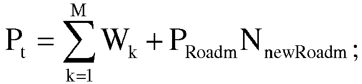
- 3. The power consumption Pt of the ODU service or STM service is:
- (1) when the routing paths are all wavelength links:

- (2) when the routing paths are all virtual links:

- (3) when the routing paths are composed of wavelength links and virtual links:

- (1) when the routing paths are all wavelength links:
- 4. The power consumption Pt of the ethernet service is:
- (1) when the routing paths are all wavelength links:

- (2) when the routing paths are all packet layer virtual links:

- (3) when the routing paths include both the packet layer virtual links and the OTN layer virtual links:

- (4) when the routing paths include the wavelength links, and also include the packet layer virtual links and the OTN layer virtual links:

- (1) when the routing paths are all wavelength links:
- The ordinary person skilled in the art can understand that all or part of the steps in the above method can be completed by a program instructing related hardware, and the program can be stored in a computer readable memory medium, such as a read-only memory, magnetic disk or optical disk and so on. Alternatively, all or part of the steps of the above embodiments also can be implemented by using one or multiple integrated circuits. Correspondingly, each module/unit in the above embodiments can be implemented in a form of hardware, and also can be implemented in a form of software function module. The present invention is not limited to any combination of hardware and software in a specific form.
- The above description is only the preferred embodiments of the present invention, which does not limit the patent scope of the embodiments of the present invention due to this. Equivalent structures or equivalent flow transformations made by using the contents of the descriptions and accompanying drawings of the present invention, or equivalent structures or equivalent flow transformations directly or indirectly applied in other related technical fields, are all also included in the patent protection scope of the present invention.
- In the embodiments of the present invention, the wavelength link in the path is converted into the virtual link, the service path planning and wavelength allocation are finished with the power consumption as a weight between the nodes, so as to obtain a path with the minimum power consumption to implement the service routing, which is conducive to reducing the power consumption of services, thereby optimizing the power consumption of the entire network to the greatest extent.
Claims (6)
- A grooming method for a packet optical transport network ,OTN, comprising:step A, according to an arrangement order of various services, planning a path from a service source node to a service target node in an ith service in a topology set graph; wherein an initial value of i is 1; wherein the ith service comprises a synchronous transport module, STM, service, an optical channel, OCH, service and an ethernet service;step B, when the path comprises a wavelength link in a physical link, removing the wavelength link, and establishing a virtual link between a link source node and a link target node of the removed wavelength link;step C, updating capacities of various links in the path;step D, calculating a weight of a newly established virtual link, and adding the newly established virtual link and the corresponding weight to the topology set graph; andstep E, if i+1, returning to the step A, until all services are finished, wherein, i is a positive integer; characterized in thatwhen the ith service is the STM service, the step B comprises:step B21, when the path comprises a wavelength link in a physical link, removing the wavelength link, and establishing an OTN layer virtual link between a link source node and a link target node of the removed wavelength link;step B22, when the path comprises an OTN layer virtual link, retaining the OTN layer virtual link;step B23, when a physical link comprised in a newly established OTN layer virtual link has existed in a previous OTN layer virtual link, and a capacity of the previous OTN layer virtual link meets capacity requirements of the ith service, splitting the previous OTN layer virtual link into a plurality of OTN layer virtual sublinks;step B24, calculating the sum of power consumptions P1 of the plurality of OTN layer virtual sublinks, power consumption P2 of the newly established OTN layer virtual link and power consumption P3 of the previous OTN layer virtual link;step B25, when P1≤P2+P3, removing the newly established OTN layer virtual link, and establishing a virtual link according to the plurality of split OTN layer virtual sublinks for the previous OTN layer virtual link;step B26, when P1>P2+P3, retaining the newly established OTN layer virtual link; andstep B27, when no path is found, determining that service path searching fails, and executing the step E;wherein, when the ith service is the OCH service, the step B comprises:step B11, when the path comprises a wavelength link in a physical link, removing the wavelength link, and establishing an optical transport network OTN layer virtual link between a link source node and a link target node of the removed wavelength link; andstep B12, when no path is found, determining that service path searching fails, and executing the step E;wherein, when the ith service is the ethernet service, the step B comprises:step B31, when the path comprises a wavelength link in a physical link, removing the wavelength link, and respectively establishing an OTN layer virtual link and a packet layer virtual link between a link source node and a link target node of the removed wavelength link;step B32, when the path comprises a packet layer virtual link, establishing a packet layer virtual link between a link source node and a link target node of the OTN layer virtual link;step B33, when the path comprises a packet layer virtual link, retaining the packet layer virtual link;step B34, when a physical link comprised in a newly established OTN layer virtual link has existed in a prvious OTN layer virtual link, and a capacity of the prvious OTN layer virtual link meets capacity requirements of the ith service, splitting the previous OTN layer virtual link into a plurality of OTN layer virtual sublinks;step B35, calculating the sum of power consumptions P1 of the plurality of OTN layer virtual sublinks, power consumption P2 of the newly established OTN layer virtual link, and power consumption P3 of the previous OTN layer virtual link;step B36, when P1≤P2+P3, removing the newly established OTN layer virtual link, and establishing a virtual link according to the plurality of split OTN layer virtual sublinks for the previous OTN layer virtual link;step B37, when P1>P2+P3, retaining the newly established OTN layer virtual link; andstep B38, when no path is found, determining that service path searching fails, and executing the step E.
- The grooming method for the packet optical transport network according to claim 1, before the step A, further comprising:sorting categories of various services, and arranging OCH services at first place, STM services at second place, and ethernet services at last place; andorderly arranging the OCH services from large to small according to service capacities, orderly arranging the STM services from large to small according to service capacities, and orderly arranging the ethernet services from high to low according to priorities.
- The grooming method for the packet optical transport network according to any one of claim 1, before the step A, further comprising:calculating a weight Wj=PT+N0×PA+PR of a jth segment of physical link in the topology set graph; wherein PT is power consumption of an optical transmitter in the jth segment of physical link, PA is power consumption of an optical amplifier in the jth segment of physical link, PR is power consumption of an optical receiver in the jth segment of physical link, and No is the number of optical amplifiers in the jth segment of physical link; andupdating the weight Wj of the jth segment of physical link to a corresponding physical link in the topology set graph, wherein, j is a positive integer.
- A grooming apparatus for a packet optical transport network, OTN, comprising:a path planning module (10), configured to: according to an arrangement order of various services, plan a path from a service source node to a service target node in an ith service in a topology set graph; wherein an initial value of i is 1; wherein the ith service comprises a synchronous transport module, STM, service, an optical channel, OCH, service and an ethernet service;a link establishment module (20), configured to: when the path comprises a wavelength link in a physical link, remove the wavelength link, and establish a virtual link between a link source node and a link target node of the removed wavelength link;a capacity update module (30), configured to: update capacities of various links in the path; anda topology set graph update module (40), configured to: calculate a weight of a newly established virtual link, and add the newly established virtual link and the corresponding weight to the topology set graph, wherein, i is a positive integer; characterized in that,when the ith service is the STM service, the link establishment module (20) is configured to:when the path comprises a wavelength link in a physical link, remove the wavelength link, and establish an OTN layer virtual link between a link source node and a link target node of the removed wavelength link;when the path comprises an OTN layer virtual link, retain the OTN layer virtual link;when a physical link comprised in a newly established OTN layer virtual link has existed in a previous OTN layer virtual link, and a capacity of the previous OTN layer virtual link meets capacity requirements of the ith service, split the previous OTN layer virtual link into a plurality of OTN layer virtual sublinks;calculate the sum of power consumptions P1 of the plurality of OTN layer virtual sublinks, power consumption P2 of the newly established OTN layer virtual link and power consumption P3 of the previous OTN layer virtual link;when P1≤P2+P3, remove the newly established OTN layer virtual link, and establish a virtual link according to the plurality of split OTN layer virtual sublinks for the previous OTN layer virtual link;when P1>P2+P3, retain the newly established OTN layer virtual link; andwhen no path is found, determine that service path searching fails;wherein, when the ith service is the OCH service, the link establishment module (20) is configured to:when the path comprises a wavelength link in a physical link, remove the wavelength link, and establish an optical transport network OTN layer virtual link between a link source node and a link target node of the removed wavelength link; andwhen no path is found, determine that service path searching fails;wherein, when the ith service is the ethernet service, the link establishment module (20) is configured to:when the path comprises a wavelength link in a physical link, remove the wavelength link, and respectively establish an OTN layer virtual link and a packet layer virtual link between a link source node and a link target node of the removed wavelength link;when the path comprises a packet layer virtual link, establish a packet layer virtual link between a link source node and a link target node of the OTN layer virtual link;when the path comprises a packet layer virtual link, retain the packet layer virtual link;when a physical link comprised in a newly established OTN layer virtual link has existed in a previous OTN layer virtual link, and a capacity of the previous OTN layer virtual link meets capacity requirements of the ith service, split the previous OTN layer virtual link into a plurality of OTN layer virtual sublinks;calculate the sum of power consumptions P1 of the plurality of OTN layer virtual sublinks, power consumption P2 of the newly established OTN layer virtual link and power consumption P3 of the previous OTN layer virtual link;when P1≤P2+P3, remove the newly established OTN layer virtual link, and establish a virtual link according to the plurality of split OTN layer virtual sublinks for the previous OTN layer virtual link;when P1>P2+P3, retain the newly established OTN layer virtual link; andwhen no path is found, determine that service path searching fails.
- The grooming apparatus for the packet optical transport network according to claim 4, further comprising a service sorting module (50), configured to:sort categories of various services, and arrange OCH services at first place, STM services at second place, and ethernet services at last place; andorderly arrange the OCH services from large to small according to service capacities, orderly arrange the STM services from large to small according to service capacities, and orderly arrange the ethernet services from high to low according to priorities.
- The grooming apparatus for the packet optical transport network according claim 4, wherein, the topology set graph update module (40) is further configured to:calculate a weight Wj=PT+N0×PA+PR of a jth segment of physical link in the topology set graph; wherein PT is power consumption of an optical transmitter in the jth segment of physical link, PA is power consumption of an optical amplifier in the jth segment of physical link, PR is power consumption of an optical receiver in the jth segment of physical link, and No is the number of optical amplifiers in the jth segment of physical link; andupdate the weight Wj of the jth segment of physical link to a corresponding physical link in the topology set graph, wherein, j is a positive integer.
Applications Claiming Priority (2)
| Application Number | Priority Date | Filing Date | Title |
|---|---|---|---|
| CN201310452296.6A CN104518961B (en) | 2013-09-27 | 2013-09-27 | Method and device for grooming a packet optical transport network |
| PCT/CN2014/075453 WO2014180228A1 (en) | 2013-09-27 | 2014-04-16 | Grooming method and device for packet optical transport network |
Publications (3)
| Publication Number | Publication Date |
|---|---|
| EP3038302A1 EP3038302A1 (en) | 2016-06-29 |
| EP3038302A4 EP3038302A4 (en) | 2016-08-17 |
| EP3038302B1 true EP3038302B1 (en) | 2020-02-12 |
Family
ID=51866696
Family Applications (1)
| Application Number | Title | Priority Date | Filing Date |
|---|---|---|---|
| EP14794779.0A Active EP3038302B1 (en) | 2013-09-27 | 2014-04-16 | Grooming method and device for packet optical transport network |
Country Status (4)
| Country | Link |
|---|---|
| US (1) | US9820020B2 (en) |
| EP (1) | EP3038302B1 (en) |
| CN (1) | CN104518961B (en) |
| WO (1) | WO2014180228A1 (en) |
Families Citing this family (8)
| Publication number | Priority date | Publication date | Assignee | Title |
|---|---|---|---|---|
| KR101909364B1 (en) * | 2014-03-24 | 2018-10-17 | 텔레호낙티에볼라게트 엘엠 에릭슨(피유비엘) | A method to provide elasticity in transport network virtualisation |
| CN106302159B (en) * | 2015-06-08 | 2019-08-20 | 中国移动通信集团设计院有限公司 | A method and device for generating an optimal path |
| CN106487548B (en) * | 2015-08-26 | 2020-09-15 | 南京中兴新软件有限责任公司 | Method and device for processing POTN virtual interface |
| CN106911491B (en) * | 2015-12-23 | 2020-03-03 | 中国联合网络通信集团有限公司 | Data transmission method and device |
| US10263705B1 (en) | 2018-06-22 | 2019-04-16 | At&T Intellectual Property I, L.P. | Multi-layer system capacity planning |
| CN112422225B (en) * | 2020-10-16 | 2022-03-22 | 北京邮电大学 | Traffic grooming method in hybrid grid optical network and related equipment |
| CN113726560B (en) * | 2021-08-12 | 2023-08-29 | 中盈优创资讯科技有限公司 | Method and device for acquiring meta value suggestion of backbone link of operator |
| CN114039920B (en) * | 2021-10-19 | 2022-07-12 | 苏州大学 | Method and system for load balancing traffic grooming based on IP over Quasi-CWDM network |
Family Cites Families (5)
| Publication number | Priority date | Publication date | Assignee | Title |
|---|---|---|---|---|
| CA2418384A1 (en) | 2002-02-06 | 2003-08-06 | Nippon Telegraph And Telephone Corporation | Optical network, optical cross-connect apparatus, photonic-ip network, and node |
| CN100361445C (en) * | 2004-12-17 | 2008-01-09 | 电子科技大学 | A comprehensive service grooming method for wavelength division multiplexing optical network |
| CN102056034B (en) * | 2010-12-27 | 2013-01-02 | 东北大学 | Robust routing and channelizing system and method in optical network based on symmetrical hose tube model |
| JP5776510B2 (en) | 2011-05-27 | 2015-09-09 | 富士通株式会社 | Network management apparatus and optical path setting method |
| CN102970225B (en) * | 2012-11-13 | 2015-04-15 | 同济大学 | Internet protocol (IP) over wavelength division multiplexing (WDM) network energy-aware routing method based on multipriority business |
-
2013
- 2013-09-27 CN CN201310452296.6A patent/CN104518961B/en active Active
-
2014
- 2014-04-16 EP EP14794779.0A patent/EP3038302B1/en active Active
- 2014-04-16 US US15/024,965 patent/US9820020B2/en not_active Expired - Fee Related
- 2014-04-16 WO PCT/CN2014/075453 patent/WO2014180228A1/en not_active Ceased
Non-Patent Citations (1)
| Title |
|---|
| None * |
Also Published As
| Publication number | Publication date |
|---|---|
| US9820020B2 (en) | 2017-11-14 |
| EP3038302A4 (en) | 2016-08-17 |
| CN104518961A (en) | 2015-04-15 |
| EP3038302A1 (en) | 2016-06-29 |
| CN104518961B (en) | 2019-03-01 |
| WO2014180228A1 (en) | 2014-11-13 |
| US20160249118A1 (en) | 2016-08-25 |
Similar Documents
| Publication | Publication Date | Title |
|---|---|---|
| US9820020B2 (en) | Grooming method and device for packet optical transport network | |
| US12289208B2 (en) | Optimization method and system for minimizing network energy consumption based on traffic grooming | |
| CN101459469B (en) | Optical layer scheduling method for network element and network management control system | |
| CN106487548B (en) | Method and device for processing POTN virtual interface | |
| CN107959528A (en) | The network plan method and network of multi-core optical fiber network traffics asymmetric traffic transmission | |
| CN111342889B (en) | Risk separation protection path searching method and system for safety and stability control type service | |
| CN105721192A (en) | Method and apparatus for realizing capacity planning | |
| US9755893B2 (en) | Provisioning virtual optical networks | |
| Fernandez-Palacios et al. | Elastic optical networking: An operators perspective | |
| CN105245307A (en) | Method and device for determining a communication path in a communication network | |
| CN115209248A (en) | Method for allocating switchable resources based on crosstalk-aware spectrum in multi-core elastic optical network | |
| CN111355660A (en) | Routing determination method and system based on capacity balance and relative time delay | |
| CN102868624B (en) | The control device of electro-optical composite network node, control system and control method | |
| Yuan et al. | A routing modulation and spectrum assignment algorithm for semi-filterless elastic optical networks | |
| CN108616782A (en) | A kind of frequency spectrum distributing method based on the optimization of non-intersecting connection group in elastic optical network | |
| CN101360347B (en) | Routing Selection Method in Wavelength Routing Optical Network | |
| Džanko et al. | Dedicated path protection for optical networks based on function programmable nodes | |
| CN105763283B (en) | A method for optimizing configuration of optical add-drop multiplexer in wavelength division multiplexing optical network | |
| WO2012103852A2 (en) | Method and device for wavelength-division multiplexing network planning | |
| Lu et al. | Asymmetric CDC ROADM architecture for efficient support of bi-directional asymmetric traffic demands | |
| CN107888282B (en) | Circuit whole-course route calculation method of optical transmission network | |
| CN104506442A (en) | Multipoint-to-multipoint multicast business optical grooming method for flexible grid optical network | |
| CN101136712B (en) | A method for improving path finding efficiency in network communication transmission | |
| CN116938368A (en) | Resource allocation method and device for space division multiplexing flexible grid optical network | |
| WO2014019167A1 (en) | Planning method and device for wavelength division multiplexing network |
Legal Events
| Date | Code | Title | Description |
|---|---|---|---|
| PUAI | Public reference made under article 153(3) epc to a published international application that has entered the european phase |
Free format text: ORIGINAL CODE: 0009012 |
|
| 17P | Request for examination filed |
Effective date: 20160325 |
|
| AK | Designated contracting states |
Kind code of ref document: A1 Designated state(s): AL AT BE BG CH CY CZ DE DK EE ES FI FR GB GR HR HU IE IS IT LI LT LU LV MC MK MT NL NO PL PT RO RS SE SI SK SM TR |
|
| AX | Request for extension of the european patent |
Extension state: BA ME |
|
| A4 | Supplementary search report drawn up and despatched |
Effective date: 20160720 |
|
| RIC1 | Information provided on ipc code assigned before grant |
Ipc: H04L 12/721 20130101AFI20160714BHEP Ipc: H04Q 11/00 20060101ALI20160714BHEP Ipc: H04J 14/02 20060101ALI20160714BHEP |
|
| DAX | Request for extension of the european patent (deleted) | ||
| RIC1 | Information provided on ipc code assigned before grant |
Ipc: H04Q 11/00 20060101ALI20180829BHEP Ipc: H04J 14/02 20060101ALI20180829BHEP Ipc: H04L 12/721 20130101AFI20180829BHEP Ipc: H04L 12/24 20060101ALI20180829BHEP |
|
| STAA | Information on the status of an ep patent application or granted ep patent |
Free format text: STATUS: EXAMINATION IS IN PROGRESS |
|
| 17Q | First examination report despatched |
Effective date: 20181016 |
|
| GRAP | Despatch of communication of intention to grant a patent |
Free format text: ORIGINAL CODE: EPIDOSNIGR1 |
|
| STAA | Information on the status of an ep patent application or granted ep patent |
Free format text: STATUS: GRANT OF PATENT IS INTENDED |
|
| INTG | Intention to grant announced |
Effective date: 20190826 |
|
| GRAS | Grant fee paid |
Free format text: ORIGINAL CODE: EPIDOSNIGR3 |
|
| GRAA | (expected) grant |
Free format text: ORIGINAL CODE: 0009210 |
|
| STAA | Information on the status of an ep patent application or granted ep patent |
Free format text: STATUS: THE PATENT HAS BEEN GRANTED |
|
| AK | Designated contracting states |
Kind code of ref document: B1 Designated state(s): AL AT BE BG CH CY CZ DE DK EE ES FI FR GB GR HR HU IE IS IT LI LT LU LV MC MK MT NL NO PL PT RO RS SE SI SK SM TR |
|
| REG | Reference to a national code |
Ref country code: GB Ref legal event code: FG4D |
|
| REG | Reference to a national code |
Ref country code: CH Ref legal event code: EP |
|
| REG | Reference to a national code |
Ref country code: AT Ref legal event code: REF Ref document number: 1233577 Country of ref document: AT Kind code of ref document: T Effective date: 20200215 |
|
| REG | Reference to a national code |
Ref country code: IE Ref legal event code: FG4D |
|
| REG | Reference to a national code |
Ref country code: DE Ref legal event code: R096 Ref document number: 602014060948 Country of ref document: DE |
|
| PG25 | Lapsed in a contracting state [announced via postgrant information from national office to epo] |
Ref country code: NO Free format text: LAPSE BECAUSE OF FAILURE TO SUBMIT A TRANSLATION OF THE DESCRIPTION OR TO PAY THE FEE WITHIN THE PRESCRIBED TIME-LIMIT Effective date: 20200512 Ref country code: FI Free format text: LAPSE BECAUSE OF FAILURE TO SUBMIT A TRANSLATION OF THE DESCRIPTION OR TO PAY THE FEE WITHIN THE PRESCRIBED TIME-LIMIT Effective date: 20200212 Ref country code: RS Free format text: LAPSE BECAUSE OF FAILURE TO SUBMIT A TRANSLATION OF THE DESCRIPTION OR TO PAY THE FEE WITHIN THE PRESCRIBED TIME-LIMIT Effective date: 20200212 |
|
| REG | Reference to a national code |
Ref country code: LT Ref legal event code: MG4D |
|
| REG | Reference to a national code |
Ref country code: NL Ref legal event code: MP Effective date: 20200212 |
|
| PG25 | Lapsed in a contracting state [announced via postgrant information from national office to epo] |
Ref country code: GR Free format text: LAPSE BECAUSE OF FAILURE TO SUBMIT A TRANSLATION OF THE DESCRIPTION OR TO PAY THE FEE WITHIN THE PRESCRIBED TIME-LIMIT Effective date: 20200513 Ref country code: IS Free format text: LAPSE BECAUSE OF FAILURE TO SUBMIT A TRANSLATION OF THE DESCRIPTION OR TO PAY THE FEE WITHIN THE PRESCRIBED TIME-LIMIT Effective date: 20200612 Ref country code: BG Free format text: LAPSE BECAUSE OF FAILURE TO SUBMIT A TRANSLATION OF THE DESCRIPTION OR TO PAY THE FEE WITHIN THE PRESCRIBED TIME-LIMIT Effective date: 20200512 Ref country code: SE Free format text: LAPSE BECAUSE OF FAILURE TO SUBMIT A TRANSLATION OF THE DESCRIPTION OR TO PAY THE FEE WITHIN THE PRESCRIBED TIME-LIMIT Effective date: 20200212 Ref country code: LV Free format text: LAPSE BECAUSE OF FAILURE TO SUBMIT A TRANSLATION OF THE DESCRIPTION OR TO PAY THE FEE WITHIN THE PRESCRIBED TIME-LIMIT Effective date: 20200212 Ref country code: HR Free format text: LAPSE BECAUSE OF FAILURE TO SUBMIT A TRANSLATION OF THE DESCRIPTION OR TO PAY THE FEE WITHIN THE PRESCRIBED TIME-LIMIT Effective date: 20200212 |
|
| PG25 | Lapsed in a contracting state [announced via postgrant information from national office to epo] |
Ref country code: NL Free format text: LAPSE BECAUSE OF FAILURE TO SUBMIT A TRANSLATION OF THE DESCRIPTION OR TO PAY THE FEE WITHIN THE PRESCRIBED TIME-LIMIT Effective date: 20200212 |
|
| PG25 | Lapsed in a contracting state [announced via postgrant information from national office to epo] |
Ref country code: ES Free format text: LAPSE BECAUSE OF FAILURE TO SUBMIT A TRANSLATION OF THE DESCRIPTION OR TO PAY THE FEE WITHIN THE PRESCRIBED TIME-LIMIT Effective date: 20200212 Ref country code: PT Free format text: LAPSE BECAUSE OF FAILURE TO SUBMIT A TRANSLATION OF THE DESCRIPTION OR TO PAY THE FEE WITHIN THE PRESCRIBED TIME-LIMIT Effective date: 20200705 Ref country code: DK Free format text: LAPSE BECAUSE OF FAILURE TO SUBMIT A TRANSLATION OF THE DESCRIPTION OR TO PAY THE FEE WITHIN THE PRESCRIBED TIME-LIMIT Effective date: 20200212 Ref country code: SK Free format text: LAPSE BECAUSE OF FAILURE TO SUBMIT A TRANSLATION OF THE DESCRIPTION OR TO PAY THE FEE WITHIN THE PRESCRIBED TIME-LIMIT Effective date: 20200212 Ref country code: SM Free format text: LAPSE BECAUSE OF FAILURE TO SUBMIT A TRANSLATION OF THE DESCRIPTION OR TO PAY THE FEE WITHIN THE PRESCRIBED TIME-LIMIT Effective date: 20200212 Ref country code: EE Free format text: LAPSE BECAUSE OF FAILURE TO SUBMIT A TRANSLATION OF THE DESCRIPTION OR TO PAY THE FEE WITHIN THE PRESCRIBED TIME-LIMIT Effective date: 20200212 Ref country code: LT Free format text: LAPSE BECAUSE OF FAILURE TO SUBMIT A TRANSLATION OF THE DESCRIPTION OR TO PAY THE FEE WITHIN THE PRESCRIBED TIME-LIMIT Effective date: 20200212 Ref country code: RO Free format text: LAPSE BECAUSE OF FAILURE TO SUBMIT A TRANSLATION OF THE DESCRIPTION OR TO PAY THE FEE WITHIN THE PRESCRIBED TIME-LIMIT Effective date: 20200212 Ref country code: CZ Free format text: LAPSE BECAUSE OF FAILURE TO SUBMIT A TRANSLATION OF THE DESCRIPTION OR TO PAY THE FEE WITHIN THE PRESCRIBED TIME-LIMIT Effective date: 20200212 |
|
| REG | Reference to a national code |
Ref country code: DE Ref legal event code: R097 Ref document number: 602014060948 Country of ref document: DE |
|
| REG | Reference to a national code |
Ref country code: AT Ref legal event code: MK05 Ref document number: 1233577 Country of ref document: AT Kind code of ref document: T Effective date: 20200212 |
|
| PG25 | Lapsed in a contracting state [announced via postgrant information from national office to epo] |
Ref country code: MC Free format text: LAPSE BECAUSE OF FAILURE TO SUBMIT A TRANSLATION OF THE DESCRIPTION OR TO PAY THE FEE WITHIN THE PRESCRIBED TIME-LIMIT Effective date: 20200212 |
|
| REG | Reference to a national code |
Ref country code: CH Ref legal event code: PL |
|
| PLBE | No opposition filed within time limit |
Free format text: ORIGINAL CODE: 0009261 |
|
| STAA | Information on the status of an ep patent application or granted ep patent |
Free format text: STATUS: NO OPPOSITION FILED WITHIN TIME LIMIT |
|
| 26N | No opposition filed |
Effective date: 20201113 |
|
| PG25 | Lapsed in a contracting state [announced via postgrant information from national office to epo] |
Ref country code: IT Free format text: LAPSE BECAUSE OF FAILURE TO SUBMIT A TRANSLATION OF THE DESCRIPTION OR TO PAY THE FEE WITHIN THE PRESCRIBED TIME-LIMIT Effective date: 20200212 Ref country code: CH Free format text: LAPSE BECAUSE OF NON-PAYMENT OF DUE FEES Effective date: 20200430 Ref country code: LI Free format text: LAPSE BECAUSE OF NON-PAYMENT OF DUE FEES Effective date: 20200430 Ref country code: LU Free format text: LAPSE BECAUSE OF NON-PAYMENT OF DUE FEES Effective date: 20200416 Ref country code: AT Free format text: LAPSE BECAUSE OF FAILURE TO SUBMIT A TRANSLATION OF THE DESCRIPTION OR TO PAY THE FEE WITHIN THE PRESCRIBED TIME-LIMIT Effective date: 20200212 |
|
| REG | Reference to a national code |
Ref country code: BE Ref legal event code: MM Effective date: 20200430 |
|
| PG25 | Lapsed in a contracting state [announced via postgrant information from national office to epo] |
Ref country code: PL Free format text: LAPSE BECAUSE OF FAILURE TO SUBMIT A TRANSLATION OF THE DESCRIPTION OR TO PAY THE FEE WITHIN THE PRESCRIBED TIME-LIMIT Effective date: 20200212 Ref country code: SI Free format text: LAPSE BECAUSE OF FAILURE TO SUBMIT A TRANSLATION OF THE DESCRIPTION OR TO PAY THE FEE WITHIN THE PRESCRIBED TIME-LIMIT Effective date: 20200212 Ref country code: BE Free format text: LAPSE BECAUSE OF NON-PAYMENT OF DUE FEES Effective date: 20200430 |
|
| GBPC | Gb: european patent ceased through non-payment of renewal fee |
Effective date: 20200512 |
|
| PG25 | Lapsed in a contracting state [announced via postgrant information from national office to epo] |
Ref country code: IE Free format text: LAPSE BECAUSE OF NON-PAYMENT OF DUE FEES Effective date: 20200416 Ref country code: GB Free format text: LAPSE BECAUSE OF NON-PAYMENT OF DUE FEES Effective date: 20200512 |
|
| REG | Reference to a national code |
Ref country code: DE Ref legal event code: R079 Ref document number: 602014060948 Country of ref document: DE Free format text: PREVIOUS MAIN CLASS: H04L0012721000 Ipc: H04L0045000000 |
|
| PG25 | Lapsed in a contracting state [announced via postgrant information from national office to epo] |
Ref country code: TR Free format text: LAPSE BECAUSE OF FAILURE TO SUBMIT A TRANSLATION OF THE DESCRIPTION OR TO PAY THE FEE WITHIN THE PRESCRIBED TIME-LIMIT Effective date: 20200212 Ref country code: MT Free format text: LAPSE BECAUSE OF FAILURE TO SUBMIT A TRANSLATION OF THE DESCRIPTION OR TO PAY THE FEE WITHIN THE PRESCRIBED TIME-LIMIT Effective date: 20200212 Ref country code: CY Free format text: LAPSE BECAUSE OF FAILURE TO SUBMIT A TRANSLATION OF THE DESCRIPTION OR TO PAY THE FEE WITHIN THE PRESCRIBED TIME-LIMIT Effective date: 20200212 |
|
| PG25 | Lapsed in a contracting state [announced via postgrant information from national office to epo] |
Ref country code: MK Free format text: LAPSE BECAUSE OF FAILURE TO SUBMIT A TRANSLATION OF THE DESCRIPTION OR TO PAY THE FEE WITHIN THE PRESCRIBED TIME-LIMIT Effective date: 20200212 Ref country code: AL Free format text: LAPSE BECAUSE OF FAILURE TO SUBMIT A TRANSLATION OF THE DESCRIPTION OR TO PAY THE FEE WITHIN THE PRESCRIBED TIME-LIMIT Effective date: 20200212 |
|
| PGFP | Annual fee paid to national office [announced via postgrant information from national office to epo] |
Ref country code: FR Payment date: 20240308 Year of fee payment: 11 |
|
| PGFP | Annual fee paid to national office [announced via postgrant information from national office to epo] |
Ref country code: DE Payment date: 20240306 Year of fee payment: 11 |
|
| REG | Reference to a national code |
Ref country code: DE Ref legal event code: R119 Ref document number: 602014060948 Country of ref document: DE |
|
| PG25 | Lapsed in a contracting state [announced via postgrant information from national office to epo] |
Ref country code: DE Free format text: LAPSE BECAUSE OF NON-PAYMENT OF DUE FEES Effective date: 20251104 |
|
| PG25 | Lapsed in a contracting state [announced via postgrant information from national office to epo] |
Ref country code: FR Free format text: LAPSE BECAUSE OF NON-PAYMENT OF DUE FEES Effective date: 20250430 |