EP3037777A2 - Method for measuring object and smart device - Google Patents
Method for measuring object and smart device Download PDFInfo
- Publication number
- EP3037777A2 EP3037777A2 EP15196250.3A EP15196250A EP3037777A2 EP 3037777 A2 EP3037777 A2 EP 3037777A2 EP 15196250 A EP15196250 A EP 15196250A EP 3037777 A2 EP3037777 A2 EP 3037777A2
- Authority
- EP
- European Patent Office
- Prior art keywords
- track
- parameter
- measured
- smart device
- finger
- Prior art date
- Legal status (The legal status is an assumption and is not a legal conclusion. Google has not performed a legal analysis and makes no representation as to the accuracy of the status listed.)
- Granted
Links
Images


Classifications
-
- G—PHYSICS
- G06—COMPUTING OR CALCULATING; COUNTING
- G06T—IMAGE DATA PROCESSING OR GENERATION, IN GENERAL
- G06T7/00—Image analysis
- G06T7/60—Analysis of geometric attributes
- G06T7/62—Analysis of geometric attributes of area, perimeter, diameter or volume
-
- G—PHYSICS
- G01—MEASURING; TESTING
- G01B—MEASURING LENGTH, THICKNESS OR SIMILAR LINEAR DIMENSIONS; MEASURING ANGLES; MEASURING AREAS; MEASURING IRREGULARITIES OF SURFACES OR CONTOURS
- G01B11/00—Measuring arrangements characterised by the use of optical techniques
- G01B11/02—Measuring arrangements characterised by the use of optical techniques for measuring length, width or thickness
- G01B11/022—Measuring arrangements characterised by the use of optical techniques for measuring length, width or thickness by means of tv-camera scanning
-
- G—PHYSICS
- G01—MEASURING; TESTING
- G01B—MEASURING LENGTH, THICKNESS OR SIMILAR LINEAR DIMENSIONS; MEASURING ANGLES; MEASURING AREAS; MEASURING IRREGULARITIES OF SURFACES OR CONTOURS
- G01B11/00—Measuring arrangements characterised by the use of optical techniques
- G01B11/02—Measuring arrangements characterised by the use of optical techniques for measuring length, width or thickness
-
- G—PHYSICS
- G01—MEASURING; TESTING
- G01B—MEASURING LENGTH, THICKNESS OR SIMILAR LINEAR DIMENSIONS; MEASURING ANGLES; MEASURING AREAS; MEASURING IRREGULARITIES OF SURFACES OR CONTOURS
- G01B11/00—Measuring arrangements characterised by the use of optical techniques
- G01B11/28—Measuring arrangements characterised by the use of optical techniques for measuring areas
-
- G—PHYSICS
- G01—MEASURING; TESTING
- G01B—MEASURING LENGTH, THICKNESS OR SIMILAR LINEAR DIMENSIONS; MEASURING ANGLES; MEASURING AREAS; MEASURING IRREGULARITIES OF SURFACES OR CONTOURS
- G01B11/00—Measuring arrangements characterised by the use of optical techniques
- G01B11/28—Measuring arrangements characterised by the use of optical techniques for measuring areas
- G01B11/285—Measuring arrangements characterised by the use of optical techniques for measuring areas using photoelectric detection means
-
- G—PHYSICS
- G06—COMPUTING OR CALCULATING; COUNTING
- G06T—IMAGE DATA PROCESSING OR GENERATION, IN GENERAL
- G06T2207/00—Indexing scheme for image analysis or image enhancement
- G06T2207/10—Image acquisition modality
- G06T2207/10016—Video; Image sequence
-
- G—PHYSICS
- G06—COMPUTING OR CALCULATING; COUNTING
- G06T—IMAGE DATA PROCESSING OR GENERATION, IN GENERAL
- G06T2207/00—Indexing scheme for image analysis or image enhancement
- G06T2207/20—Special algorithmic details
- G06T2207/20092—Interactive image processing based on input by user
-
- G—PHYSICS
- G06—COMPUTING OR CALCULATING; COUNTING
- G06T—IMAGE DATA PROCESSING OR GENERATION, IN GENERAL
- G06T2207/00—Indexing scheme for image analysis or image enhancement
- G06T2207/30—Subject of image; Context of image processing
- G06T2207/30196—Human being; Person
-
- G—PHYSICS
- G06—COMPUTING OR CALCULATING; COUNTING
- G06T—IMAGE DATA PROCESSING OR GENERATION, IN GENERAL
- G06T2207/00—Indexing scheme for image analysis or image enhancement
- G06T2207/30—Subject of image; Context of image processing
- G06T2207/30241—Trajectory
Definitions
- the present disclosure relates to a smart device technology, and more particularly to a method for measuring an object and a smart device.
- Embodiments of the present disclosure seek to solve at least one of the problems existing in the related art to at least some extent.
- a method for measuring an object includes: detecting by a smart device a track of a target object moving along the object to be measured; calculating a parameter of the track by the smart device according to the track; and acquiring a parameter of the object to be measured by the smart device according to the parameter of the track.
- a smart device includes: a detecting module, configured to detect a track of a target object moving along an object to be measured; a calculating module, configured to calculate a parameter of the track according to the track; and an acquiring module, configured to acquire a parameter of the object to be measured according to the parameter of the track.
- the smart device by using a novel human-computer interaction mode, a length, size or area of an object with regular or irregular physical shape may be measured. Moreover, the measurement of an object with the smart device is quite efficient, conveniently and accurate.
- first and second are used herein for purposes of description and are not intended to indicate or imply relative importance or significance or to imply the number of indicated technical features.
- the feature defined with “first” and “second” may comprise one or more of this feature.
- a plurality of means two or more than two, unless specified otherwise.
- a method for measuring an object includes steps of: detecting by a smart device a track of a target object moving along the object to be measured; calculating a parameter of the track by the smart device according to the track; and acquiring a parameter of the object to be measured by the smart device according to the parameter of the track.
- Fig. 1 is a flow chart of the method for measuring an object according to an embodiment of the present disclosure. As shown in Fig. 1 , the method includes following steps.
- a track of a target object moving along the object to be measured is detected by a smart device.
- the smart device may include but is not limited to a smart mobile terminal (such as smart phone, panel computer, notebook computer, personal digital assistant, e-book) and a smart wearable device (such as smart glasses, smart watch).
- a smart mobile terminal such as smart phone, panel computer, notebook computer, personal digital assistant, e-book
- a smart wearable device such as smart glasses, smart watch
- the smart device may have a camera configured to shoot the track of the target object moving along the object to be measured. It should be noted that the track of the target object moving along the object to be measured may be detected by other ways in other embodiments, which shall not be illustrated in details herein.
- the object to be measured may be an object with regular shape (such as cube, cuboid, sphere) or irregular shape.
- the detected track of the target object moving along the object to be measured may be a straight line or a curve with either regular shape or irregular shape.
- a parameter of the track is calculated by the smart device according to the track.
- the parameter may be a length or an area, such that a length or an area of the object to be measured may be calculated respectively according to a length or an area of the track.
- the track of the target object moving along the object to be measured is detected by the smart device so as to obtain a track image, and then the track image may be analyzed so as to calculate the parameter of the track.
- the track image may be analyzed by image processing technology so as to calculate the parameter of the track.
- a parameter of the object to be measured is acquired by the smart device according to the parameter of the track.
- a ratio of the parameter of the track to a map parameter of the target object on the track may be calculated by the smart device according to the parameter of the track and the map parameter of the target object on the track, and then the parameter of the object to be measured is calculated according to the ratio and a parameter of the target object input by a user or stored in the smart device.
- the method may further include a step of broadcasting the parameter of the object to be measured by voice in the smart device, or displaying the parameter of the object to be measured in the smart device. In this way, it is convenient for the user to obtain the measurement result and a user experience is improved.
- Fig. 2 is a flow chart of a method for measuring an object according to a specific embodiment of the present disclosure.
- the target object is a finger
- the parameter is a length.
- the method includes following steps.
- a track of a target object moving along the object to be measured is detected by a smart device.
- the smart device may include but is not limited to a smart mobile terminal (such as smart phone, panel computer, notebook computer, personal digital assistant, e-book) and a smart wearable device (such as smart glasses, smart watch).
- a smart mobile terminal such as smart phone, panel computer, notebook computer, personal digital assistant, e-book
- a smart wearable device such as smart glasses, smart watch
- the smart device may have a camera configured to shoot the track of the target object moving along the object to be measured. It should be noted that the track of the target object moving along the object to be measured may be detected by other ways in other embodiments, which shall not be illustrated in details herein.
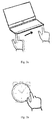
- Fig. 3a is a schematic view showing a finger moving along a side of a notebook computer according to an embodiment of the present disclosure
- Fig. 3b is a schematic view showing a finger moving along a dial of an alarm clock according to an embodiment of the present disclosure.
- the tracks of the finger moving along the objects to be measured during above two processes may be shot by the camera of the smart device. It can be seen from Fig. 3a and Fig. 3b that, not only a straight line track but also a circular track may be detected by the smart device. Certainly, in other embodiments, tracks of the finger or other target object moving along the object to be measured with regular shape or irregular shape also may be detected by the smart device.
- the object to be measured may be an object with regular shape (such as cube, cuboid, sphere) or irregular shape.
- the detected track of the target object moving along the object to be measured may be a straight line or a curve with either regular shape or irregular shape.
- a length of the track is calculated by the smart device according to the track.
- the track of the target object moving along the object to be measured is detected by the smart device so as to obtain a track image, and then the track image may be analyzed so as to calculate the length of the track.
- the track image may be analyzed by image processing technology so as to calculate the length of the track.
- a finger width of the finger is acquired.
- the finger width of the finger may be input manually by the user of the smart device via an input interface (such as a touch keyboard, an audio input interface).
- an input interface such as a touch keyboard, an audio input interface.
- one of finger widths stored in the smart device may be selected as the finger width of the finger according to the user's instruction.
- a ratio of a length of the track to a map width of the finger on the track is acquired, and a length of the object to be measured is calculated according to the ratio and the width of the finger.
- the map width of the finger on the track may be acquired by analyzing the track image obtained at step S202.
- the length of the object to be measured is broadcasted by voice or displayed in the smart device.
- the length of the object to be measured may be measured according to the length of the track. Moreover, this method is quite efficient and conveniently, a measurement result is more accurate, and a user experience is improved.
- Fig. 4 is a flow chart of a method for measuring an object according to a specific embodiment of the present disclosure.
- the target object is a finger
- the parameter is an area.
- the method includes following steps.
- a track of a target object moving along the object to be measured is detected by a smart device.
- the smart device may include but is not limited to a smart mobile terminal (such as smart phone, panel computer, notebook computer, personal digital assistant, e-book) and a smart wearable device (such as smart glasses, smart watch).
- a smart mobile terminal such as smart phone, panel computer, notebook computer, personal digital assistant, e-book
- a smart wearable device such as smart glasses, smart watch
- the smart device may have a camera configured to shoot the track of the target object moving along the object to be measured. It should be noted that the track of the target object moving along the object to be measured may be detected by other ways in other embodiments, which shall not be illustrated in details herein.
- the object to be measured may be an object with regular shape (such as cube, cuboid, sphere) or irregular shape.
- the detected track of the target object moving along the object to be measured may be a straight line or a curve with either regular shape or irregular shape.
- an area of the track is calculated by the smart device according to the track.
- the track of the target object moving along the object to be measured is detected by the smart device so as to obtain a track image, and then the track image may be analyzed so as to calculate the area of the track.
- the track image may be analyzed by image processing technology so as to calculate the area of the track.
- step S403 an area of a nail of the finger is acquired.
- the area of the nail of the finger may be input manually by the user of the smart device via an input interface (such as a touch keyboard, an audio input interface).
- an input interface such as a touch keyboard, an audio input interface.
- one of areas of the nail of the finger stored in the smart device may be selected as the area of the nail of the finger according to the user's instruction.
- a track of the nail is acquired according to the track of the finger, and an area of the object to be measured is calculated according to the track of the nail.
- a map area of the nail on the track of the finger may be acquired by analyzing the track image obtained at step S402.
- the area of the object to be measured is broadcasted by voice or displayed in the smart device.
- the method for measuring an object using the smart device, by detecting the track of the finger moving along the object to be measured and acquiring the area of the track, the area of the object to be measured may be measured according to the area of the track. Moreover, this method is quite efficient and conveniently, a measurement result is more accurate, and a user experience is improved.
- a smart device includes: a detecting module, configured to detect a track of a target object moving along the object to be measured; a calculating module, configured to calculate a parameter of the track according to the track; and an acquiring module, configured to acquire a parameter of the object to be measured according to the parameter of the track.
- Fig. 5 is a block diagram of a smart device according to an embodiment of the present disclosure. As shown in Fig. 5 , the smart device includes: a detecting module 10, a calculating module 20 and an acquiring module 30.
- the smart device may include but is not limited to a smart mobile terminal (such as smart phone, panel computer, notebook computer, personal digital assistant, e-book) and a smart wearable device (such as smart glasses, smart watch).
- a smart mobile terminal such as smart phone, panel computer, notebook computer, personal digital assistant, e-book
- a smart wearable device such as smart glasses, smart watch
- the detecting module 10 is configured to detect a track of a target object moving along the object to be measured.
- the detecting module 10 may be a camera configured to shoot the track of the target object moving along the object to be measured. It should be noted that the detecting module 10 may detect the track of the target object moving along the object to be measured by other ways in other embodiments, which shall not be illustrated in details herein.
- the object to be measured may be an object with regular shape (such as cube, cuboid, sphere) or irregular shape.
- the detected track of the target object moving along the object to be measured may be a straight line or a curve with either regular shape or irregular shape.
- the calculating module 20 is configured to calculate a parameter of the track according to the track.
- the parameter may be a length or an area, such that a length or an area of the object to be measured may be calculated respectively according to a length or an area of the track by the calculating module 20.
- the track of the target object moving along the object to be measured is detected by the detecting module 10 so as to obtain a track image, and then the track image may be analyzed by the calculating module 20 so as to calculate the parameter of the track.
- the track image may be analyzed by the calculating module 20 with image processing technology so as to calculate the parameter of the track.
- the acquiring module 30 is configured to acquire a parameter of the object to be measured according to the parameter of the track.
- a ratio of the parameter of the track to a map parameter of the target object on the track may be calculated by the acquiring module 30, and then the parameter of the object to be measured is calculated according to the ratio and a parameter of the target object input by a user or stored in the smart device.
- the target object may be a finger
- the parameter may be a length
- the acquiring module 30 is configured to acquire a finger width of the finger, to acquire a ratio of a length of the track to a map width of the finger on the track, and to calculate a length of the object to be measured according to the ratio and the finger width of the finger.
- the target object may be a finger
- the parameter may be an area
- the acquiring module 30 is configured to acquire an area of a nail of the finger, to acquire a track of the nail according to the track of the finger, and to calculate an area of the object to be measured accessed by the nail according to the track of the nail.
- Fig. 3a is a schematic view showing a finger moving along a side of a notebook computer according to an embodiment of the present disclosure
- Fig. 3b is a schematic view showing a finger moving along a dial of an alarm clock according to an embodiment of the present disclosure.
- the tracks of the finger moving along the objects to be measured during above two processes may be shot by the camera of the smart device. It can be seen from Fig. 3a and Fig. 3b that, not only a straight line track but also a circular track may be detected by the smart device. Certainly, in other embodiments, tracks of the finger or other target object moving along the object to be measured with regular shape or irregular shape also may be detected by the smart device.
- the map width of the finger on the track may be acquired by analyzing the track image obtained.
- a map area of the nail on the track of the finger may be acquired by analyzing the track image obtained.
- the width of the finger and the area of the nail of the finger may be input manually by the user of the smart device via an input interface (such as a touch keyboard, an audio input interface).
- an input interface such as a touch keyboard, an audio input interface.
- one of areas of the nail of the finger stored in the smart device may be selected as the area of the nail of the finger according to the user's instruction, and one of finger widths stored in the smart device may be selected as the finger width according to the user's instruction.
- the smart device by using a novel human-computer interaction mode, a length, size or area of an object with regular or irregular physical shape may be measured. Moreover, the measurement of an object with the smart device is quite efficient, conveniently and accurate.
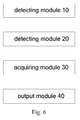
- Fig. 6 is a block diagram of a smart device according to another embodiment of the present disclosure. As shown in Fig. 6 , the smart device includes: a detecting module 10, a calculating module 20, an acquiring module 30 and an output module 40.
- the detecting module 10, the calculating module 20 and the acquiring module 30 may refer to the embodiment described above with reference to Fig. 5 , which will not described in details herein.
- the output module 40 is configured to broadcast the parameter of the object to be measured by voice or to display the parameter of the object to be measured, after the parameter of the object to be measured is acquired by the smart device according to the parameter of the track.
- the logic and/or step described in other manners herein or shown in the flow chart, for example, a particular sequence table of executable instructions for realizing the logical function may be specifically achieved in any computer readable medium to be used by the instruction execution system, device or equipment (such as the system based on computers, the system comprising processors or other systems capable of obtaining the instruction from the instruction execution system, device and equipment and executing the instruction), or to be used in combination with the instruction execution system, device and equipment.
- the computer readable medium may be any device adaptive for including, storing, communicating, propagating or transferring programs to be used by or in combination with the instruction execution system, device or equipment.
- the computer readable medium include but are not limited to: an electronic connection (an electronic device) with one or more wires, a portable computer enclosure (a magnetic device), a random access memory (RAM), a read only memory (ROM), an erasable programmable read-only memory (EPROM or a flash memory), an optical fiber device and a portable compact disk read-only memory (CDROM).
- the computer readable medium may even be a paper or other appropriate medium capable of printing programs thereon, this is because, for example, the paper or other appropriate medium may be optically scanned and then edited, decrypted or processed with other appropriate methods when necessary to obtain the programs in an electric manner, and then the programs may be stored in the computer memories.
- each part of the present disclosure may be realized by the hardware, software, firmware or their combination.
- a plurality of steps or methods may be realized by the software or firmware stored in the memory and executed by the appropriate instruction execution system.
- the steps or methods may be realized by one or a combination of the following techniques known in the art: a discrete logic circuit having a logic gate circuit for realizing a logic function of a data signal, an application-specific integrated circuit having an appropriate combination logic gate circuit, a programmable gate array (PGA), a field programmable gate array (FPGA), etc.
- each function cell of the embodiments of the present disclosure may be integrated in a processing module, or these cells may be separate physical existence, or two or more cells are integrated in a processing module.
- the integrated module may be realized in a form of hardware or in a form of software function modules. When the integrated module is realized in a form of software function module and is sold or used as a standalone product, the integrated module may be stored in a computer readable storage medium.
- the storage medium mentioned above may be read-only memories, magnetic disks or CD, etc.
Landscapes
- Physics & Mathematics (AREA)
- General Physics & Mathematics (AREA)
- Engineering & Computer Science (AREA)
- Geometry (AREA)
- Computer Vision & Pattern Recognition (AREA)
- Theoretical Computer Science (AREA)
- Length Measuring Devices By Optical Means (AREA)
- Radar Systems Or Details Thereof (AREA)
- User Interface Of Digital Computer (AREA)
Abstract

Description
- The present disclosure relates to a smart device technology, and more particularly to a method for measuring an object and a smart device.
- During the daily life, particularly in various design fields, such as modem product industrial design, urban planning and design, fashion design, there are great demands for measuring sizes of various products. Physical rulers are used as the measurement tools in the conventional mode. Such conventional mode, however, is generally restricted by the physical shape of an object, such that it is difficult to measure an object with irregular shape. Moreover, the conventional mode is not convenient to operate.
- With the developments of modem digital application products, digital measurement is also applied for measuring an object. Presently, novel electronic products using infrared ray measurement or ultrasonic measurement are used for measuring an object. However, a length, size or area of an object with irregular shape cannot be obtained efficiently and quickly by these methods. Therefore, a method for measuring an object efficiently, conveniently and accurately is needed.
- Embodiments of the present disclosure seek to solve at least one of the problems existing in the related art to at least some extent.
- According to a first aspect of the present disclosure, a method for measuring an object is provided. The method includes: detecting by a smart device a track of a target object moving along the object to be measured; calculating a parameter of the track by the smart device according to the track; and acquiring a parameter of the object to be measured by the smart device according to the parameter of the track.
- With the method for measuring an object, by using a novel human-computer interaction mode, a length, size or area of an object with regular or irregular physical shape may be measured. Moreover, this method is quite efficient and conveniently, and a measurement result is more accurate.
- According to a second aspect of the present disclosure, a smart device is provided. The smart device includes: a detecting module, configured to detect a track of a target object moving along an object to be measured; a calculating module, configured to calculate a parameter of the track according to the track; and an acquiring module, configured to acquire a parameter of the object to be measured according to the parameter of the track.
- With the smart device, by using a novel human-computer interaction mode, a length, size or area of an object with regular or irregular physical shape may be measured. Moreover, the measurement of an object with the smart device is quite efficient, conveniently and accurate.
- The above summary of the present disclosure is not intended to describe each disclosed embodiment or every implementation of the present disclosure. The Figures and the detailed description which follow more particularly exemplify illustrative embodiments.
- Additional aspects and advantages of embodiments of present disclosure will be given in part in the following descriptions, become apparent in part from the following descriptions, or be learned from the practice of the embodiments of the present disclosure.
- These and other aspects and advantages of embodiments of the present disclosure will become apparent and more readily appreciated from the following descriptions made with reference to the drawings, in which:
-
Fig. 1 is a flow chart of a method for measuring an object according to an embodiment of the present disclosure; -
Fig. 2 is a flow chart of a method for measuring an object according to a specific embodiment of the present disclosure; -
Fig. 3a is a schematic view showing a finger moving along a side of a notebook computer according to an embodiment of the present disclosure; -
Fig. 3b is a schematic view showing a finger moving along a dial of an alarm clock according to an embodiment of the present disclosure; -
Fig. 4 is a flow chart of a method for measuring an object according to a specific embodiment of the present disclosure; -
Fig. 5 is a block diagram of a smart device according to an embodiment of the present disclosure; -
Fig. 6 is a block diagram of a smart device according to another embodiment of the present disclosure. - Reference will be made in detail to embodiments of the present disclosure. The embodiments described herein with reference to drawings are explanatory, illustrative, and used to generally understand the present disclosure. The embodiments shall not be construed to limit the present disclosure. The same or similar elements and the elements having same or similar functions are denoted by like reference numerals throughout the descriptions.
- In addition, terms such as "first" and "second" are used herein for purposes of description and are not intended to indicate or imply relative importance or significance or to imply the number of indicated technical features. Thus, the feature defined with "first" and "second" may comprise one or more of this feature. In the description of the present invention, "a plurality of" means two or more than two, unless specified otherwise.
- A method for measuring an object and a smart device according to embodiments of the present disclosure are described below with reference to drawings.
- According to a first aspect of the present disclosure, a method for measuring an object is provided. The method includes steps of: detecting by a smart device a track of a target object moving along the object to be measured; calculating a parameter of the track by the smart device according to the track; and acquiring a parameter of the object to be measured by the smart device according to the parameter of the track.
-
Fig. 1 is a flow chart of the method for measuring an object according to an embodiment of the present disclosure. As shown inFig. 1 , the method includes following steps. - At step S101, a track of a target object moving along the object to be measured is detected by a smart device.
- The smart device may include but is not limited to a smart mobile terminal (such as smart phone, panel computer, notebook computer, personal digital assistant, e-book) and a smart wearable device (such as smart glasses, smart watch).
- In one embodiment, the smart device may have a camera configured to shoot the track of the target object moving along the object to be measured. It should be noted that the track of the target object moving along the object to be measured may be detected by other ways in other embodiments, which shall not be illustrated in details herein.
- The object to be measured may be an object with regular shape (such as cube, cuboid, sphere) or irregular shape. The detected track of the target object moving along the object to be measured may be a straight line or a curve with either regular shape or irregular shape.
- At step S102, a parameter of the track is calculated by the smart device according to the track.
- In one embodiment, the parameter may be a length or an area, such that a length or an area of the object to be measured may be calculated respectively according to a length or an area of the track.
- Specifically, the track of the target object moving along the object to be measured is detected by the smart device so as to obtain a track image, and then the track image may be analyzed so as to calculate the parameter of the track. Particularly, the track image may be analyzed by image processing technology so as to calculate the parameter of the track.
- At step S103, a parameter of the object to be measured is acquired by the smart device according to the parameter of the track.
- In one embodiment, a ratio of the parameter of the track to a map parameter of the target object on the track may be calculated by the smart device according to the parameter of the track and the map parameter of the target object on the track, and then the parameter of the object to be measured is calculated according to the ratio and a parameter of the target object input by a user or stored in the smart device.
- With the method for measuring an object, by using a novel human-computer interaction mode, a length, size or area of an object with regular or irregular physical shape may be measured. Moreover, this method is quite efficient and conveniently, and a measurement result is more accurate.
- In one embodiment, after the parameter of the object to be measured is acquired by the smart device according to the parameter of the track, the method may further include a step of broadcasting the parameter of the object to be measured by voice in the smart device, or displaying the parameter of the object to be measured in the smart device. In this way, it is convenient for the user to obtain the measurement result and a user experience is improved.
-
Fig. 2 is a flow chart of a method for measuring an object according to a specific embodiment of the present disclosure. In this embodiment, the target object is a finger, and the parameter is a length. As shown inFig. 2 , the method includes following steps. - At step S201, a track of a target object moving along the object to be measured is detected by a smart device.
- The smart device may include but is not limited to a smart mobile terminal (such as smart phone, panel computer, notebook computer, personal digital assistant, e-book) and a smart wearable device (such as smart glasses, smart watch).
- In one embodiment, the smart device may have a camera configured to shoot the track of the target object moving along the object to be measured. It should be noted that the track of the target object moving along the object to be measured may be detected by other ways in other embodiments, which shall not be illustrated in details herein.
- For example,
Fig. 3a is a schematic view showing a finger moving along a side of a notebook computer according to an embodiment of the present disclosure, andFig. 3b is a schematic view showing a finger moving along a dial of an alarm clock according to an embodiment of the present disclosure. The tracks of the finger moving along the objects to be measured during above two processes may be shot by the camera of the smart device. It can be seen fromFig. 3a and Fig. 3b that, not only a straight line track but also a circular track may be detected by the smart device. Certainly, in other embodiments, tracks of the finger or other target object moving along the object to be measured with regular shape or irregular shape also may be detected by the smart device. - The object to be measured may be an object with regular shape (such as cube, cuboid, sphere) or irregular shape. The detected track of the target object moving along the object to be measured may be a straight line or a curve with either regular shape or irregular shape.
- At step S202, a length of the track is calculated by the smart device according to the track.
- Specifically, the track of the target object moving along the object to be measured is detected by the smart device so as to obtain a track image, and then the track image may be analyzed so as to calculate the length of the track. Particularly, the track image may be analyzed by image processing technology so as to calculate the length of the track.
- At step S203, a finger width of the finger is acquired.
- In one embodiment, the finger width of the finger may be input manually by the user of the smart device via an input interface (such as a touch keyboard, an audio input interface). Certainly, one of finger widths stored in the smart device may be selected as the finger width of the finger according to the user's instruction.
- At step S204, a ratio of a length of the track to a map width of the finger on the track is acquired, and a length of the object to be measured is calculated according to the ratio and the width of the finger.
- In one embodiment, the map width of the finger on the track may be acquired by analyzing the track image obtained at step S202. The ratio a/b of the length a of the track to the map width b of the finger on the track is acquired, and the length A of the object to be measured is calculated according to the ratio a/b and the finger width B of the finger, i.e., A=B/(a/b).
- Alternatively, at step S205, the length of the object to be measured is broadcasted by voice or displayed in the smart device.
- With the method for measuring an object, using the smart device, by detecting the track of the finger moving along the object to be measured and acquiring the length of the track, the length of the object to be measured may be measured according to the length of the track. Moreover, this method is quite efficient and conveniently, a measurement result is more accurate, and a user experience is improved.
-
Fig. 4 is a flow chart of a method for measuring an object according to a specific embodiment of the present disclosure. In this embodiment, the target object is a finger, and the parameter is an area. As shown inFig. 4 , the method includes following steps. - At step S401, a track of a target object moving along the object to be measured is detected by a smart device.
- The smart device may include but is not limited to a smart mobile terminal (such as smart phone, panel computer, notebook computer, personal digital assistant, e-book) and a smart wearable device (such as smart glasses, smart watch).
- In one embodiment, the smart device may have a camera configured to shoot the track of the target object moving along the object to be measured. It should be noted that the track of the target object moving along the object to be measured may be detected by other ways in other embodiments, which shall not be illustrated in details herein.
- The object to be measured may be an object with regular shape (such as cube, cuboid, sphere) or irregular shape. The detected track of the target object moving along the object to be measured may be a straight line or a curve with either regular shape or irregular shape.
- At step S402, an area of the track is calculated by the smart device according to the track.
- Specifically, the track of the target object moving along the object to be measured is detected by the smart device so as to obtain a track image, and then the track image may be analyzed so as to calculate the area of the track. Particularly, the track image may be analyzed by image processing technology so as to calculate the area of the track.
- At step S403, an area of a nail of the finger is acquired.
- In one embodiment, the area of the nail of the finger may be input manually by the user of the smart device via an input interface (such as a touch keyboard, an audio input interface). Certainly, one of areas of the nail of the finger stored in the smart device may be selected as the area of the nail of the finger according to the user's instruction.
- At step S404, a track of the nail is acquired according to the track of the finger, and an area of the object to be measured is calculated according to the track of the nail.
- In one embodiment, a map area of the nail on the track of the finger may be acquired by analyzing the track image obtained at step S402. A ratio s1/s2 of an area s1 of the track of the nail to the map area s2 of the nail on the track of the finger is acquired, and the area S1 of the object to be measured is calculated according to the ratio s1/s2 and the area S2 of the nail, i.e., S1=S2/(s1/s2).
- Alternatively, at step S405, the area of the object to be measured is broadcasted by voice or displayed in the smart device.
- With the method for measuring an object, using the smart device, by detecting the track of the finger moving along the object to be measured and acquiring the area of the track, the area of the object to be measured may be measured according to the area of the track. Moreover, this method is quite efficient and conveniently, a measurement result is more accurate, and a user experience is improved.
- According to a second aspect of the present disclosure, a smart device is provided. The smart device includes: a detecting module, configured to detect a track of a target object moving along the object to be measured; a calculating module, configured to calculate a parameter of the track according to the track; and an acquiring module, configured to acquire a parameter of the object to be measured according to the parameter of the track.
-
Fig. 5 is a block diagram of a smart device according to an embodiment of the present disclosure. As shown inFig. 5 , the smart device includes: a detectingmodule 10, a calculatingmodule 20 and an acquiringmodule 30. - The smart device may include but is not limited to a smart mobile terminal (such as smart phone, panel computer, notebook computer, personal digital assistant, e-book) and a smart wearable device (such as smart glasses, smart watch).
- The detecting
module 10 is configured to detect a track of a target object moving along the object to be measured. - In one embodiment, the detecting
module 10 may be a camera configured to shoot the track of the target object moving along the object to be measured. It should be noted that the detectingmodule 10 may detect the track of the target object moving along the object to be measured by other ways in other embodiments, which shall not be illustrated in details herein. - The object to be measured may be an object with regular shape (such as cube, cuboid, sphere) or irregular shape. The detected track of the target object moving along the object to be measured may be a straight line or a curve with either regular shape or irregular shape.
- The calculating
module 20 is configured to calculate a parameter of the track according to the track. - In one embodiment, the parameter may be a length or an area, such that a length or an area of the object to be measured may be calculated respectively according to a length or an area of the track by the calculating
module 20. - Specifically, the track of the target object moving along the object to be measured is detected by the detecting
module 10 so as to obtain a track image, and then the track image may be analyzed by the calculatingmodule 20 so as to calculate the parameter of the track. Particularly, the track image may be analyzed by the calculatingmodule 20 with image processing technology so as to calculate the parameter of the track. - The acquiring
module 30 is configured to acquire a parameter of the object to be measured according to the parameter of the track. - In one embodiment, a ratio of the parameter of the track to a map parameter of the target object on the track may be calculated by the acquiring
module 30, and then the parameter of the object to be measured is calculated according to the ratio and a parameter of the target object input by a user or stored in the smart device. - In one embodiment, the target object may be a finger, the parameter may be a length, and the acquiring
module 30 is configured to acquire a finger width of the finger, to acquire a ratio of a length of the track to a map width of the finger on the track, and to calculate a length of the object to be measured according to the ratio and the finger width of the finger. - In another embodiment, the target object may be a finger, the parameter may be an area, and the acquiring
module 30 is configured to acquire an area of a nail of the finger, to acquire a track of the nail according to the track of the finger, and to calculate an area of the object to be measured accessed by the nail according to the track of the nail. - For example,
Fig. 3a is a schematic view showing a finger moving along a side of a notebook computer according to an embodiment of the present disclosure, andFig. 3b is a schematic view showing a finger moving along a dial of an alarm clock according to an embodiment of the present disclosure. The tracks of the finger moving along the objects to be measured during above two processes may be shot by the camera of the smart device. It can be seen fromFig. 3a and Fig. 3b that, not only a straight line track but also a circular track may be detected by the smart device. Certainly, in other embodiments, tracks of the finger or other target object moving along the object to be measured with regular shape or irregular shape also may be detected by the smart device. - Specifically, in one embodiment, the map width of the finger on the track may be acquired by analyzing the track image obtained. The ratio a/b of the length a of the track to the map width b of the finger on the track is acquired, and the length A of the object to be measured is calculated according to the ratio a/b and the finger width B of the finger, i.e., A=B/(a/b).
- In one embodiment, a map area of the nail on the track of the finger may be acquired by analyzing the track image obtained. A ratio s1/s2 of an area s1 of the track of the nail to the map area s2 of the nail on the track of the finger is acquired, and the area S1 of the object to be measured is calculated according to the ratio s1/s2 and the area S2 of the nail, i.e., S1=S2/(s1/s2).
- In one embodiment, the width of the finger and the area of the nail of the finger may be input manually by the user of the smart device via an input interface (such as a touch keyboard, an audio input interface). Certainly, one of areas of the nail of the finger stored in the smart device may be selected as the area of the nail of the finger according to the user's instruction, and one of finger widths stored in the smart device may be selected as the finger width according to the user's instruction.
- With the smart device, by using a novel human-computer interaction mode, a length, size or area of an object with regular or irregular physical shape may be measured. Moreover, the measurement of an object with the smart device is quite efficient, conveniently and accurate.
-
Fig. 6 is a block diagram of a smart device according to another embodiment of the present disclosure. As shown inFig. 6 , the smart device includes: a detectingmodule 10, a calculatingmodule 20, an acquiringmodule 30 and anoutput module 40. - Specifically, the detecting
module 10, the calculatingmodule 20 and the acquiringmodule 30 may refer to the embodiment described above with reference toFig. 5 , which will not described in details herein. - The
output module 40 is configured to broadcast the parameter of the object to be measured by voice or to display the parameter of the object to be measured, after the parameter of the object to be measured is acquired by the smart device according to the parameter of the track. By providing theoutput module 40, it is convenient for the user to obtain the measurement result and a user experience is improved. - Any process or method described in a flow chart or described herein in other ways may be understood to include one or more modules, segments or portions of codes of executable instructions for achieving specific logical functions or steps in the process, and the scope of a preferred embodiment of the present disclosure includes other implementations, which should be understood by those skilled in the art.
- The logic and/or step described in other manners herein or shown in the flow chart, for example, a particular sequence table of executable instructions for realizing the logical function, may be specifically achieved in any computer readable medium to be used by the instruction execution system, device or equipment (such as the system based on computers, the system comprising processors or other systems capable of obtaining the instruction from the instruction execution system, device and equipment and executing the instruction), or to be used in combination with the instruction execution system, device and equipment. As to the specification, "the computer readable medium" may be any device adaptive for including, storing, communicating, propagating or transferring programs to be used by or in combination with the instruction execution system, device or equipment. More specific examples of the computer readable medium include but are not limited to: an electronic connection (an electronic device) with one or more wires, a portable computer enclosure (a magnetic device), a random access memory (RAM), a read only memory (ROM), an erasable programmable read-only memory (EPROM or a flash memory), an optical fiber device and a portable compact disk read-only memory (CDROM). In addition, the computer readable medium may even be a paper or other appropriate medium capable of printing programs thereon, this is because, for example, the paper or other appropriate medium may be optically scanned and then edited, decrypted or processed with other appropriate methods when necessary to obtain the programs in an electric manner, and then the programs may be stored in the computer memories.
- It should be understood that each part of the present disclosure may be realized by the hardware, software, firmware or their combination. In the above embodiments, a plurality of steps or methods may be realized by the software or firmware stored in the memory and executed by the appropriate instruction execution system. For example, if it is realized by the hardware, likewise in another embodiment, the steps or methods may be realized by one or a combination of the following techniques known in the art: a discrete logic circuit having a logic gate circuit for realizing a logic function of a data signal, an application-specific integrated circuit having an appropriate combination logic gate circuit, a programmable gate array (PGA), a field programmable gate array (FPGA), etc.
- Those skilled in the art shall understand that all or parts of the steps in the above exemplifying method of the present disclosure may be achieved by commanding the related hardware with programs. The programs may be stored in a computer readable storage medium, and the programs include one or a combination of the steps in the method embodiments of the present disclosure when run on a computer.
- In addition, each function cell of the embodiments of the present disclosure may be integrated in a processing module, or these cells may be separate physical existence, or two or more cells are integrated in a processing module. The integrated module may be realized in a form of hardware or in a form of software function modules. When the integrated module is realized in a form of software function module and is sold or used as a standalone product, the integrated module may be stored in a computer readable storage medium.
- The storage medium mentioned above may be read-only memories, magnetic disks or CD, etc.
- Reference throughout this specification to "an embodiment," "some embodiments," "one embodiment", "another example," "an example," "a specific example," or "some examples," means that a particular feature, structure, material, or characteristic described in connection with the embodiment or example is included in at least one embodiment or example of the present disclosure. Thus, the appearances of the phrases such as "in some embodiments," "in one embodiment", "in an embodiment", "in another example," "in an example," "in a specific example," or "in some examples," in various places throughout this specification are not necessarily referring to the same embodiment or example of the present disclosure. Furthermore, the particular features, structures, materials, or characteristics may be combined in any suitable manner in one or more embodiments or examples.
- Although explanatory embodiments have been shown and described, it would be appreciated by those skilled in the art that the above embodiments cannot be construed to limit the present disclosure, and changes, alternatives, and modifications can be made in the embodiments without departing from scope of the present disclosure.
Claims (15)
- A method for measuring an object, comprising:detecting by a smart device a track of a target object moving along the object to be measured;calculating a parameter of the track by the smart device according to the track; andacquiring a parameter of the object to be measured by the smart device according to the parameter of the track.
- The method according to claim 1, wherein the target object is a finger, the parameter is a length, and acquiring a parameter of the object to be measured by the smart device according to the parameter of the track comprises:acquiring a finger width of the finger;acquiring a ratio of a length of the track to a map width of the finger on the track; andcalculating a length of the object to be measured according to the ratio and the finger width.
- The method according to claim 1, wherein the target object is a finger, the parameter is an area, and acquiring a parameter of the object to be measured by the smart device according to the parameter of the track comprises:acquiring an area of a nail of the finger;acquiring a track of the nail according to the track of the finger; andcalculating an area of the object to be measured according to the track of the nail.
- The method according to claim 3, wherein calculating an area of the object to be measured according to the track of the nail comprises:acquiring a map area of the nail on the track of the finger;acquiring a ratio of an area of the track of the nail to the map area of the nail on the track of the finger; andcalculating an area of the object to be measured according to the ratio and the area of the nail.
- The method according to any of claims 1-4, wherein after acquiring the parameter of the object to be measured by the smart device according to the parameter of the track, further comprising:broadcasting the parameter of the object to be measured by the smart device via voice.
- The method according to any of claims 1-4, wherein after acquiring a parameter of the object to be measured by the smart device according to the parameter of the track, further comprising:displaying the parameter of the object to be measured in the smart device.
- The method according to any of claims 1-6, wherein detecting by a smart device a track of a target object moving along the object to be measured comprising:shooting by a camera of a smart device a track of a target object moving along the object to be measured.
- A smart device, comprising:a detecting module (10), configured to detect a track of a target object moving along an object to be measured;a calculating module (20), configured to calculate a parameter of the track according to the track; andan acquiring module (30), configured to acquire a parameter of the object to be measured according to the parameter of the track.
- The smart device according to claim 8, wherein the target object is a finger, the parameter is a length, and the acquiring module (30) is configured to:acquire a finger width of the finger;acquire a ratio of a length of the track to a map width of the finger on the track; andcalculate a length of the object to be measured according to the ratio and the finger width.
- The smart device according to claim 8, wherein the target object is a finger, the parameter is an area, and the acquiring module (30) is configured to:acquire an area of a nail of the finger;acquire a track of the nail according to the track of the finger; andcalculate an area of the object to be measured according to the track of the nail.
- The smart device according to claim 10, wherein the acquiring module (30) is configured to:acquire an area of a nail of the finger;acquire a track of the nail according to the track of the finger;acquire a map area of the nail on the track of the finger;acquire a ratio of an area of the track of the nail to the map area of the nail on the track of the finger; andcalculate an area of the object to be measured according to the ratio and the area of the nail.
- The smart device according to any of claims 8-11, further comprising:an output module (40), configured to broadcast the parameter of the object to be measured by voice, after acquiring the parameter of the object to be measured by the acquiring module according to the parameter of the track.
- The smart device according to any of claims 8-11, further comprising:an output module (40), configured to display the parameter of the object to be measured, after acquiring a parameter of the object to be measured by the acquiring module according to the parameter of the track.
- The smart device according to any of claims 8-13, wherein the detecting module (30) is a camera and the camera is configured to shoot the track of the target object moving along the object to be measured.
- A program product having stored therein instructions that, when executed by one or more processors of a smart device, causes the smart device to perform:detecting a track of a target object moving along an object to be measured;calculating a parameter of the track according to the track; andacquiring a parameter of the object to be measured according to the parameter of the track.
Applications Claiming Priority (1)
| Application Number | Priority Date | Filing Date | Title |
|---|---|---|---|
| CN201410808800.6A CN104461009B (en) | 2014-12-22 | 2014-12-22 | The measuring method and smart machine of object |
Publications (3)
| Publication Number | Publication Date |
|---|---|
| EP3037777A2 true EP3037777A2 (en) | 2016-06-29 |
| EP3037777A3 EP3037777A3 (en) | 2016-07-20 |
| EP3037777B1 EP3037777B1 (en) | 2020-08-19 |
Family
ID=52907201
Family Applications (1)
| Application Number | Title | Priority Date | Filing Date |
|---|---|---|---|
| EP15196250.3A Active EP3037777B1 (en) | 2014-12-22 | 2015-11-25 | Method for measuring object and smart device |
Country Status (3)
| Country | Link |
|---|---|
| US (1) | US9741135B2 (en) |
| EP (1) | EP3037777B1 (en) |
| CN (1) | CN104461009B (en) |
Families Citing this family (3)
| Publication number | Priority date | Publication date | Assignee | Title |
|---|---|---|---|---|
| JP6999542B2 (en) * | 2015-08-24 | 2022-01-18 | マイ サイズ イスラエル 2014 リミテッド | Systems and methods for measuring using portable electronic devices |
| US9965159B2 (en) * | 2015-09-30 | 2018-05-08 | Ricoh Company, Ltd. | Automatic measurement of objects in images |
| CN110044309B (en) * | 2019-04-08 | 2021-07-16 | 天津字节跳动科技有限公司 | Measuring method and device |
Family Cites Families (24)
| Publication number | Priority date | Publication date | Assignee | Title |
|---|---|---|---|---|
| US5161313A (en) | 1984-05-03 | 1992-11-10 | Rijlaarsadam Cornelis E | Tracking, measuring and calculating instrument for the determination of lengths, areas, peripheries and volumes |
| DE3602165A1 (en) * | 1986-01-24 | 1987-07-30 | Gerhard Freudenreich | Distance meter for the direct measurement and determination of lengths and distances, in particular on reduced drawings, plans and maps |
| IT1262523B (en) | 1993-06-03 | 1996-07-02 | Bruno Angilella | PEN-SHAPED DEVICE WITH MEANS TO MEASURE A LENGTH. |
| US6373579B1 (en) * | 1999-05-26 | 2002-04-16 | Hand Held Products, Inc. | Portable measurement apparatus for determinging the dimensions of an object and associated method |
| CA2421468A1 (en) * | 2002-03-14 | 2003-09-14 | Matsushita Electric Industrial Co., Ltd. | Image processing device and ultrasonic diagnostic device |
| US7376252B2 (en) * | 2003-11-25 | 2008-05-20 | Ge Medical Systems Global Technology Company, Llc | User interactive method and user interface for detecting a contour of an object |
| US7853038B2 (en) * | 2007-01-04 | 2010-12-14 | Industrial Technology Research Institute | Systems and methods for object dimension estimation |
| US20090017910A1 (en) * | 2007-06-22 | 2009-01-15 | Broadcom Corporation | Position and motion tracking of an object |
| JP4973384B2 (en) * | 2007-08-21 | 2012-07-11 | 大日本印刷株式会社 | Terminal device, program used therefor and information processing system |
| US8761434B2 (en) * | 2008-12-17 | 2014-06-24 | Sony Computer Entertainment Inc. | Tracking system calibration by reconciling inertial data with computed acceleration of a tracked object in the three-dimensional coordinate system |
| US20100303297A1 (en) * | 2009-05-30 | 2010-12-02 | Anton Mikhailov | Color calibration for object tracking |
| CN101763460A (en) * | 2009-09-02 | 2010-06-30 | 唐文兴 | Electronic length and area calculating instrument |
| IL204436A (en) * | 2010-03-11 | 2016-03-31 | Deutsche Telekom Ag | System and method for hand gesture recognition for remote control of an internet protocol tv |
| US8320622B2 (en) * | 2010-03-29 | 2012-11-27 | Sharp Laboratories Of America, Inc. | Color gradient object tracking |
| US9696897B2 (en) | 2011-10-19 | 2017-07-04 | The Regents Of The University Of California | Image-based measurement tools |
| US9939259B2 (en) * | 2012-10-04 | 2018-04-10 | Hand Held Products, Inc. | Measuring object dimensions using mobile computer |
| US20140104413A1 (en) * | 2012-10-16 | 2014-04-17 | Hand Held Products, Inc. | Integrated dimensioning and weighing system |
| CA2896985A1 (en) * | 2013-01-03 | 2014-07-10 | Meta Company | Extramissive spatial imaging digital eye glass for virtual or augmediated vision |
| US9230339B2 (en) * | 2013-01-07 | 2016-01-05 | Wexenergy Innovations Llc | System and method of measuring distances related to an object |
| US8867789B2 (en) * | 2013-01-14 | 2014-10-21 | Cyberlink Corp. | Systems and methods for tracking an object in a video |
| CN103308026A (en) * | 2013-06-28 | 2013-09-18 | 上海斐讯数据通信技术有限公司 | Method for measuring house area by mobile terminal |
| US9239950B2 (en) * | 2013-07-01 | 2016-01-19 | Hand Held Products, Inc. | Dimensioning system |
| CN103604371B (en) * | 2013-12-06 | 2017-02-15 | 上海华勤通讯技术有限公司 | Mobile terminal and object measurement method thereof |
| US9311565B2 (en) * | 2014-06-16 | 2016-04-12 | Sony Corporation | 3D scanning with depth cameras using mesh sculpting |
-
2014
- 2014-12-22 CN CN201410808800.6A patent/CN104461009B/en active Active
-
2015
- 2015-08-05 US US14/818,410 patent/US9741135B2/en not_active Expired - Fee Related
- 2015-11-25 EP EP15196250.3A patent/EP3037777B1/en active Active
Non-Patent Citations (1)
| Title |
|---|
| None |
Also Published As
| Publication number | Publication date |
|---|---|
| CN104461009B (en) | 2018-01-09 |
| US20160180550A1 (en) | 2016-06-23 |
| EP3037777B1 (en) | 2020-08-19 |
| EP3037777A3 (en) | 2016-07-20 |
| US9741135B2 (en) | 2017-08-22 |
| CN104461009A (en) | 2015-03-25 |
Similar Documents
| Publication | Publication Date | Title |
|---|---|---|
| CN104534992B (en) | A length measurement method and terminal | |
| US9418280B2 (en) | Image segmentation method and image segmentation device | |
| US20160117858A1 (en) | Computing device and method for simplifying point cloud of object | |
| IL321767A (en) | Bioinformatics systems, apparatus, and methods for performing secondary and/or tertiary processing | |
| EP3396313A1 (en) | Mobile dimensioning method and device with dynamic accuracy compatible with nist standard | |
| KR20160048901A (en) | System and method for determining the extent of a plane in an augmented reality environment | |
| CN108229364B (en) | Building contour generation method and device, computer equipment and storage medium | |
| US20160171761A1 (en) | Computing device and method for patching point clouds of object | |
| CN102980535A (en) | Angle measurement method and device | |
| US9741135B2 (en) | Method for measuring object and smart device | |
| CN108960206B (en) | Video frame processing method and device | |
| CN105300525A (en) | Temperature measuring method and terminal | |
| US20150066443A1 (en) | Computing device and method for analyzing assembly clearance between two components of product | |
| CN111222509B (en) | Target detection method and device and electronic equipment | |
| WO2023197933A1 (en) | Signal processing method and apparatus, and electronic device and medium | |
| CN116485823A (en) | Pig non-contact body weight measurement method, system, electronic equipment and storage medium | |
| CN105320584A (en) | Terminal smoothness testing method and terminal thereof | |
| US12627544B2 (en) | Method and device for detecting starting point of signal, storage medium and electronic device | |
| CN103823654A (en) | Information processing method and electronic device | |
| CN107734324B (en) | Method and system for measuring illumination uniformity of flash lamp and terminal equipment | |
| CN112560700B (en) | Information association method and device based on action analysis and electronic equipment | |
| CN110674399B (en) | Method and apparatus for determining order of search items | |
| US9761046B2 (en) | Computing device and simulation method for processing an object | |
| US11143497B2 (en) | Determination of a flexible display | |
| CN103854026A (en) | Recognition method and electronic device |
Legal Events
| Date | Code | Title | Description |
|---|---|---|---|
| PUAI | Public reference made under article 153(3) epc to a published international application that has entered the european phase |
Free format text: ORIGINAL CODE: 0009012 |
|
| PUAL | Search report despatched |
Free format text: ORIGINAL CODE: 0009013 |
|
| 17P | Request for examination filed |
Effective date: 20151125 |
|
| AK | Designated contracting states |
Kind code of ref document: A2 Designated state(s): AL AT BE BG CH CY CZ DE DK EE ES FI FR GB GR HR HU IE IS IT LI LT LU LV MC MK MT NL NO PL PT RO RS SE SI SK SM TR |
|
| AX | Request for extension of the european patent |
Extension state: BA ME |
|
| AK | Designated contracting states |
Kind code of ref document: A3 Designated state(s): AL AT BE BG CH CY CZ DE DK EE ES FI FR GB GR HR HU IE IS IT LI LT LU LV MC MK MT NL NO PL PT RO RS SE SI SK SM TR |
|
| AX | Request for extension of the european patent |
Extension state: BA ME |
|
| RIC1 | Information provided on ipc code assigned before grant |
Ipc: G01B 11/28 20060101AFI20160614BHEP Ipc: G06T 7/60 20060101ALI20160614BHEP Ipc: G01B 11/02 20060101ALI20160614BHEP |
|
| RBV | Designated contracting states (corrected) |
Designated state(s): AL AT BE BG CH CY CZ DE DK EE ES FI FR GB GR HR HU IE IS IT LI LT LU LV MC MK MT NL NO PL PT RO RS SE SI SK SM TR |
|
| GRAP | Despatch of communication of intention to grant a patent |
Free format text: ORIGINAL CODE: EPIDOSNIGR1 |
|
| STAA | Information on the status of an ep patent application or granted ep patent |
Free format text: STATUS: GRANT OF PATENT IS INTENDED |
|
| RIC1 | Information provided on ipc code assigned before grant |
Ipc: G01B 11/02 20060101ALI20200219BHEP Ipc: G01B 11/28 20060101AFI20200219BHEP |
|
| INTG | Intention to grant announced |
Effective date: 20200312 |
|
| GRAS | Grant fee paid |
Free format text: ORIGINAL CODE: EPIDOSNIGR3 |
|
| GRAA | (expected) grant |
Free format text: ORIGINAL CODE: 0009210 |
|
| STAA | Information on the status of an ep patent application or granted ep patent |
Free format text: STATUS: THE PATENT HAS BEEN GRANTED |
|
| AK | Designated contracting states |
Kind code of ref document: B1 Designated state(s): AL AT BE BG CH CY CZ DE DK EE ES FI FR GB GR HR HU IE IS IT LI LT LU LV MC MK MT NL NO PL PT RO RS SE SI SK SM TR |
|
| REG | Reference to a national code |
Ref country code: CH Ref legal event code: EP |
|
| REG | Reference to a national code |
Ref country code: DE Ref legal event code: R096 Ref document number: 602015057629 Country of ref document: DE |
|
| REG | Reference to a national code |
Ref country code: AT Ref legal event code: REF Ref document number: 1304430 Country of ref document: AT Kind code of ref document: T Effective date: 20200915 |
|
| REG | Reference to a national code |
Ref country code: IE Ref legal event code: FG4D |
|
| REG | Reference to a national code |
Ref country code: LT Ref legal event code: MG4D |
|
| REG | Reference to a national code |
Ref country code: NL Ref legal event code: MP Effective date: 20200819 |
|
| PG25 | Lapsed in a contracting state [announced via postgrant information from national office to epo] |
Ref country code: GR Free format text: LAPSE BECAUSE OF FAILURE TO SUBMIT A TRANSLATION OF THE DESCRIPTION OR TO PAY THE FEE WITHIN THE PRESCRIBED TIME-LIMIT Effective date: 20201120 Ref country code: FI Free format text: LAPSE BECAUSE OF FAILURE TO SUBMIT A TRANSLATION OF THE DESCRIPTION OR TO PAY THE FEE WITHIN THE PRESCRIBED TIME-LIMIT Effective date: 20200819 Ref country code: PT Free format text: LAPSE BECAUSE OF FAILURE TO SUBMIT A TRANSLATION OF THE DESCRIPTION OR TO PAY THE FEE WITHIN THE PRESCRIBED TIME-LIMIT Effective date: 20201221 Ref country code: NO Free format text: LAPSE BECAUSE OF FAILURE TO SUBMIT A TRANSLATION OF THE DESCRIPTION OR TO PAY THE FEE WITHIN THE PRESCRIBED TIME-LIMIT Effective date: 20201119 Ref country code: SE Free format text: LAPSE BECAUSE OF FAILURE TO SUBMIT A TRANSLATION OF THE DESCRIPTION OR TO PAY THE FEE WITHIN THE PRESCRIBED TIME-LIMIT Effective date: 20200819 Ref country code: BG Free format text: LAPSE BECAUSE OF FAILURE TO SUBMIT A TRANSLATION OF THE DESCRIPTION OR TO PAY THE FEE WITHIN THE PRESCRIBED TIME-LIMIT Effective date: 20201119 Ref country code: LT Free format text: LAPSE BECAUSE OF FAILURE TO SUBMIT A TRANSLATION OF THE DESCRIPTION OR TO PAY THE FEE WITHIN THE PRESCRIBED TIME-LIMIT Effective date: 20200819 Ref country code: HR Free format text: LAPSE BECAUSE OF FAILURE TO SUBMIT A TRANSLATION OF THE DESCRIPTION OR TO PAY THE FEE WITHIN THE PRESCRIBED TIME-LIMIT Effective date: 20200819 |
|
| REG | Reference to a national code |
Ref country code: AT Ref legal event code: MK05 Ref document number: 1304430 Country of ref document: AT Kind code of ref document: T Effective date: 20200819 |
|
| PG25 | Lapsed in a contracting state [announced via postgrant information from national office to epo] |
Ref country code: PL Free format text: LAPSE BECAUSE OF FAILURE TO SUBMIT A TRANSLATION OF THE DESCRIPTION OR TO PAY THE FEE WITHIN THE PRESCRIBED TIME-LIMIT Effective date: 20200819 Ref country code: LV Free format text: LAPSE BECAUSE OF FAILURE TO SUBMIT A TRANSLATION OF THE DESCRIPTION OR TO PAY THE FEE WITHIN THE PRESCRIBED TIME-LIMIT Effective date: 20200819 Ref country code: RS Free format text: LAPSE BECAUSE OF FAILURE TO SUBMIT A TRANSLATION OF THE DESCRIPTION OR TO PAY THE FEE WITHIN THE PRESCRIBED TIME-LIMIT Effective date: 20200819 Ref country code: NL Free format text: LAPSE BECAUSE OF FAILURE TO SUBMIT A TRANSLATION OF THE DESCRIPTION OR TO PAY THE FEE WITHIN THE PRESCRIBED TIME-LIMIT Effective date: 20200819 Ref country code: IS Free format text: LAPSE BECAUSE OF FAILURE TO SUBMIT A TRANSLATION OF THE DESCRIPTION OR TO PAY THE FEE WITHIN THE PRESCRIBED TIME-LIMIT Effective date: 20201219 |
|
| PG25 | Lapsed in a contracting state [announced via postgrant information from national office to epo] |
Ref country code: EE Free format text: LAPSE BECAUSE OF FAILURE TO SUBMIT A TRANSLATION OF THE DESCRIPTION OR TO PAY THE FEE WITHIN THE PRESCRIBED TIME-LIMIT Effective date: 20200819 Ref country code: RO Free format text: LAPSE BECAUSE OF FAILURE TO SUBMIT A TRANSLATION OF THE DESCRIPTION OR TO PAY THE FEE WITHIN THE PRESCRIBED TIME-LIMIT Effective date: 20200819 Ref country code: SM Free format text: LAPSE BECAUSE OF FAILURE TO SUBMIT A TRANSLATION OF THE DESCRIPTION OR TO PAY THE FEE WITHIN THE PRESCRIBED TIME-LIMIT Effective date: 20200819 Ref country code: CZ Free format text: LAPSE BECAUSE OF FAILURE TO SUBMIT A TRANSLATION OF THE DESCRIPTION OR TO PAY THE FEE WITHIN THE PRESCRIBED TIME-LIMIT Effective date: 20200819 Ref country code: DK Free format text: LAPSE BECAUSE OF FAILURE TO SUBMIT A TRANSLATION OF THE DESCRIPTION OR TO PAY THE FEE WITHIN THE PRESCRIBED TIME-LIMIT Effective date: 20200819 |
|
| REG | Reference to a national code |
Ref country code: DE Ref legal event code: R097 Ref document number: 602015057629 Country of ref document: DE |
|
| PG25 | Lapsed in a contracting state [announced via postgrant information from national office to epo] |
Ref country code: AT Free format text: LAPSE BECAUSE OF FAILURE TO SUBMIT A TRANSLATION OF THE DESCRIPTION OR TO PAY THE FEE WITHIN THE PRESCRIBED TIME-LIMIT Effective date: 20200819 Ref country code: AL Free format text: LAPSE BECAUSE OF FAILURE TO SUBMIT A TRANSLATION OF THE DESCRIPTION OR TO PAY THE FEE WITHIN THE PRESCRIBED TIME-LIMIT Effective date: 20200819 Ref country code: ES Free format text: LAPSE BECAUSE OF FAILURE TO SUBMIT A TRANSLATION OF THE DESCRIPTION OR TO PAY THE FEE WITHIN THE PRESCRIBED TIME-LIMIT Effective date: 20200819 |
|
| PLBE | No opposition filed within time limit |
Free format text: ORIGINAL CODE: 0009261 |
|
| STAA | Information on the status of an ep patent application or granted ep patent |
Free format text: STATUS: NO OPPOSITION FILED WITHIN TIME LIMIT |
|
| PG25 | Lapsed in a contracting state [announced via postgrant information from national office to epo] |
Ref country code: MC Free format text: LAPSE BECAUSE OF FAILURE TO SUBMIT A TRANSLATION OF THE DESCRIPTION OR TO PAY THE FEE WITHIN THE PRESCRIBED TIME-LIMIT Effective date: 20200819 Ref country code: SK Free format text: LAPSE BECAUSE OF FAILURE TO SUBMIT A TRANSLATION OF THE DESCRIPTION OR TO PAY THE FEE WITHIN THE PRESCRIBED TIME-LIMIT Effective date: 20200819 |
|
| REG | Reference to a national code |
Ref country code: CH Ref legal event code: PL |
|
| 26N | No opposition filed |
Effective date: 20210520 |
|
| PG25 | Lapsed in a contracting state [announced via postgrant information from national office to epo] |
Ref country code: LU Free format text: LAPSE BECAUSE OF NON-PAYMENT OF DUE FEES Effective date: 20201125 Ref country code: IT Free format text: LAPSE BECAUSE OF FAILURE TO SUBMIT A TRANSLATION OF THE DESCRIPTION OR TO PAY THE FEE WITHIN THE PRESCRIBED TIME-LIMIT Effective date: 20200819 |
|
| REG | Reference to a national code |
Ref country code: BE Ref legal event code: MM Effective date: 20201130 |
|
| PG25 | Lapsed in a contracting state [announced via postgrant information from national office to epo] |
Ref country code: SI Free format text: LAPSE BECAUSE OF FAILURE TO SUBMIT A TRANSLATION OF THE DESCRIPTION OR TO PAY THE FEE WITHIN THE PRESCRIBED TIME-LIMIT Effective date: 20200819 Ref country code: LI Free format text: LAPSE BECAUSE OF NON-PAYMENT OF DUE FEES Effective date: 20201130 Ref country code: CH Free format text: LAPSE BECAUSE OF NON-PAYMENT OF DUE FEES Effective date: 20201130 |
|
| PG25 | Lapsed in a contracting state [announced via postgrant information from national office to epo] |
Ref country code: IE Free format text: LAPSE BECAUSE OF NON-PAYMENT OF DUE FEES Effective date: 20201125 |
|
| PG25 | Lapsed in a contracting state [announced via postgrant information from national office to epo] |
Ref country code: TR Free format text: LAPSE BECAUSE OF FAILURE TO SUBMIT A TRANSLATION OF THE DESCRIPTION OR TO PAY THE FEE WITHIN THE PRESCRIBED TIME-LIMIT Effective date: 20200819 Ref country code: MT Free format text: LAPSE BECAUSE OF FAILURE TO SUBMIT A TRANSLATION OF THE DESCRIPTION OR TO PAY THE FEE WITHIN THE PRESCRIBED TIME-LIMIT Effective date: 20200819 Ref country code: CY Free format text: LAPSE BECAUSE OF FAILURE TO SUBMIT A TRANSLATION OF THE DESCRIPTION OR TO PAY THE FEE WITHIN THE PRESCRIBED TIME-LIMIT Effective date: 20200819 |
|
| PG25 | Lapsed in a contracting state [announced via postgrant information from national office to epo] |
Ref country code: MK Free format text: LAPSE BECAUSE OF FAILURE TO SUBMIT A TRANSLATION OF THE DESCRIPTION OR TO PAY THE FEE WITHIN THE PRESCRIBED TIME-LIMIT Effective date: 20200819 |
|
| PG25 | Lapsed in a contracting state [announced via postgrant information from national office to epo] |
Ref country code: BE Free format text: LAPSE BECAUSE OF NON-PAYMENT OF DUE FEES Effective date: 20201130 |
|
| P01 | Opt-out of the competence of the unified patent court (upc) registered |
Effective date: 20230526 |
|
| PGFP | Annual fee paid to national office [announced via postgrant information from national office to epo] |
Ref country code: FR Payment date: 20230929 Year of fee payment: 9 |
|
| PGFP | Annual fee paid to national office [announced via postgrant information from national office to epo] |
Ref country code: GB Payment date: 20231006 Year of fee payment: 9 |
|
| PGFP | Annual fee paid to national office [announced via postgrant information from national office to epo] |
Ref country code: DE Payment date: 20230929 Year of fee payment: 9 |
|
| REG | Reference to a national code |
Ref country code: DE Ref legal event code: R082 Ref document number: 602015057629 Country of ref document: DE Representative=s name: DEHNS GERMANY PARTNERSCHAFT MBB, DE |
|
| REG | Reference to a national code |
Ref country code: DE Ref legal event code: R119 Ref document number: 602015057629 Country of ref document: DE |
|
| GBPC | Gb: european patent ceased through non-payment of renewal fee |
Effective date: 20241125 |
|
| PG25 | Lapsed in a contracting state [announced via postgrant information from national office to epo] |
Ref country code: DE Free format text: LAPSE BECAUSE OF NON-PAYMENT OF DUE FEES Effective date: 20250603 |
|
| PG25 | Lapsed in a contracting state [announced via postgrant information from national office to epo] |
Ref country code: GB Free format text: LAPSE BECAUSE OF NON-PAYMENT OF DUE FEES Effective date: 20241125 |
|
| PG25 | Lapsed in a contracting state [announced via postgrant information from national office to epo] |
Ref country code: FR Free format text: LAPSE BECAUSE OF NON-PAYMENT OF DUE FEES Effective date: 20241130 |