EP3037696B1 - Self-sealing butterfly valve - Google Patents
Self-sealing butterfly valve Download PDFInfo
- Publication number
- EP3037696B1 EP3037696B1 EP14838495.1A EP14838495A EP3037696B1 EP 3037696 B1 EP3037696 B1 EP 3037696B1 EP 14838495 A EP14838495 A EP 14838495A EP 3037696 B1 EP3037696 B1 EP 3037696B1
- Authority
- EP
- European Patent Office
- Prior art keywords
- valve plate
- ring
- valve
- self
- elastic sealing
- Prior art date
- Legal status (The legal status is an assumption and is not a legal conclusion. Google has not performed a legal analysis and makes no representation as to the accuracy of the status listed.)
- Active
Links
Images





Classifications
-
- F—MECHANICAL ENGINEERING; LIGHTING; HEATING; WEAPONS; BLASTING
- F16—ENGINEERING ELEMENTS AND UNITS; GENERAL MEASURES FOR PRODUCING AND MAINTAINING EFFECTIVE FUNCTIONING OF MACHINES OR INSTALLATIONS; THERMAL INSULATION IN GENERAL
- F16K—VALVES; TAPS; COCKS; ACTUATING-FLOATS; DEVICES FOR VENTING OR AERATING
- F16K1/00—Lift valves or globe valves, i.e. cut-off apparatus with closure members having at least a component of their opening and closing motion perpendicular to the closing faces
- F16K1/16—Lift valves or globe valves, i.e. cut-off apparatus with closure members having at least a component of their opening and closing motion perpendicular to the closing faces with pivoted closure-members
- F16K1/18—Lift valves or globe valves, i.e. cut-off apparatus with closure members having at least a component of their opening and closing motion perpendicular to the closing faces with pivoted closure-members with pivoted discs or flaps
- F16K1/22—Lift valves or globe valves, i.e. cut-off apparatus with closure members having at least a component of their opening and closing motion perpendicular to the closing faces with pivoted closure-members with pivoted discs or flaps with axis of rotation crossing the valve member, e.g. butterfly valves
- F16K1/226—Shaping or arrangements of the sealing
- F16K1/2261—Shaping or arrangements of the sealing the sealing being arranged on the valve member
-
- F—MECHANICAL ENGINEERING; LIGHTING; HEATING; WEAPONS; BLASTING
- F16—ENGINEERING ELEMENTS AND UNITS; GENERAL MEASURES FOR PRODUCING AND MAINTAINING EFFECTIVE FUNCTIONING OF MACHINES OR INSTALLATIONS; THERMAL INSULATION IN GENERAL
- F16K—VALVES; TAPS; COCKS; ACTUATING-FLOATS; DEVICES FOR VENTING OR AERATING
- F16K1/00—Lift valves or globe valves, i.e. cut-off apparatus with closure members having at least a component of their opening and closing motion perpendicular to the closing faces
- F16K1/16—Lift valves or globe valves, i.e. cut-off apparatus with closure members having at least a component of their opening and closing motion perpendicular to the closing faces with pivoted closure-members
- F16K1/18—Lift valves or globe valves, i.e. cut-off apparatus with closure members having at least a component of their opening and closing motion perpendicular to the closing faces with pivoted closure-members with pivoted discs or flaps
- F16K1/22—Lift valves or globe valves, i.e. cut-off apparatus with closure members having at least a component of their opening and closing motion perpendicular to the closing faces with pivoted closure-members with pivoted discs or flaps with axis of rotation crossing the valve member, e.g. butterfly valves
- F16K1/222—Shaping of the valve member
Definitions
- the present invention relates to a self-sealing butterfly valve.
- An existing center-line butterfly valve includes a valve body, wherein a fluid passage is provided in the valve body, a valve plate of which an outer surface is covered with an elastic sealing layer is provided within the fluid passage, an upper portion of the valve plate is dynamically connected with a driving shaft which is rotatably connected to the valve body, and a lower portion of the valve plate is rotatably connected with a supporting shaft which is connected to the valve body.
- the driving shaft drives the valve plate to rotate centered with an axis of the driving shaft and the supporting shaft, to achieve opening and closing.
- the elastic sealing layer covered on an outer periphery of the valve plate is extruded and elastically deformed by the valve plate and an inner wall of the fluid passage, to achieve sealing upon being closed.
- the center-line butterfly valve of the structure above mainly has the following drawbacks: the first drawback is that it is highly demanding on rigidity of the valve body and a valve shaft; if the rigidity of the valve body is insufficient, deformation may occur under action of fluid pressure, causing lax contact between the valve body and the valve plate and consequently leakage; if the rigidity of the valve shaft is insufficient, the valve body will be displaced axially along the fluid passage under the action of fluid pressure, thereby causing valve leakage; in order to enhance the rigidity of the valve body and the valve shaft, an amount of material in use for the valve body and the valve shaft has to increase, which causes a large weight for the valve body and the valve shaft, thereby incurring a high manufacturing cost.
- the second drawback is that a larger pressure on the elastic sealing layer not only causes the valve to have large opening and closing torques, but also aggravates wear of the elastic sealing layer, which shortens a service life of the valve and is not suitable for a pipeline system that is opened and closed frequently; besides, a self-weight of the valve plate also exacerbates wear and makes the opening and closing more difficult.
- FR1339202A discloses a valve comprising a valve disc mounted in a collar or pipe connection which in turn is removably secured by bolts to the flanges of the ends of the pipes.
- the disc has in diametrically opposite regions on the axis of rotation of the disc bosses comprising blind holes of rectangular cross-section for receiving the pivot shafts which maintains the disc for rotation, the shaft being of course rotatably driven by means of the lever to operate the valve.
- the disc is completely covered by a bonded coating of elastic material which covers the outer flat faces of the disc as well as the peripheral edge of the disc. And the covering also covers all exposed surfaces of the bumps.
- DE1425647A1 discloses a flap-type seal for liquid or gas valve comprising a disc coated by plastic coating for sealing.
- JPS6012762 discloses a butterfly valve wherein a valve shaft rotatably relaxed in a valve chest, a valve body fixed to the valve shaft, and an elastic seat ring fitted in an annular recessed groove formed in the outer periphery of the valve body in the butterfly valve.
- a first technical problem to be solved by the present invention is, for addressing the above first drawback, providing a self-sealing butterfly valve that is less demanding on rigidity of a valve body and a valve shaft, may effectively decrease weights of the valve body and the valve shaft, reduces a manufacturing cost, and has a better sealing effect.
- a second technical problem to be solved by the present invention is, for addressing the above second drawback, providing a self-sealing butterfly valve that has small opening and closing torques, may further alleviate wear of an elastic sealing layer, prolongs a service lift of the valve, and is suitable for a pipeline system which is opened and closed frequently.
- a self-sealing butterfly valve includes a valve body, wherein a fluid passage is provided in the valve body, a valve plate of which an outer surface is covered with an elastic sealing layer is provided within the fluid passage, an upper portion of the valve plate is dynamically connected with a driving shaft which is rotatably connected to the valve body, a lower portion of the valve plate is rotatably connected with a supporting shaft which is connected to the valve body, and wherein the elastic sealing layer at outer edges of two end faces of the valve plate axially protrudes outwardly, forming two ring lips attached to an inner wall of the fluid passage, and the ring lips are gradually thicker from outside to inside, so that inner ring faces of the ring lips are inclined faces, and wherein an upper inflated portion for connection with the driving shaft is provided at the upper portion of the valve plate, a lower inflated portion for connection with the supporting shaft is provided at the lower portion of the valve plate, a lower surface
- a self-sealing butterfly valve includes a valve body, wherein a fluid passage is provided in the valve body, a valve plate is provided within the fluid passage, an upper portion of the valve plate is dynamically connected with a driving shaft which is rotatably connected to the valve body, a lower portion of the valve plate is rotatably connected with a supporting shaft which is connected to the valve body, and wherein the valve plate is sleeved with an elastic sealing ring which is capable of enveloping an outer periphery face of the valve plate and outer edges of two end faces of the valve plate, outer edges of two end faces of the elastic sealing ring axially protrude outwardly, forming two ring lips attached to an inner wall of the fluid passage, and the ring lips are gradually thicker from outside to inside, so that inner ring faces of the ring lips are inclined faces, and wherein an upper inflated portion for connection with the driving shaft is provided at the upper portion
- the elastic sealing ring includes a loop for covering an outer peripheral face of the valve plate, the loop has a driving shaft mounting hole and a supporting shaft mounting hole at two opposite sides, two barriers are provided at intervals on an inner wall face of the loop, the two barriers and the loop form, in concert, a mounting annular groove for sleeving the valve plate, outer side faces of two barriers form the two end faces of the elastic sealing ring, the ring lips are arranged at outer edges of the barriers, and convex ribs are circularly provided on the two end faces of the elastic sealing ring.
- the two end faces of the valve plate are respectively connected with a stop ring, inner end faces of the two stop rings are respectively attached with pressure on the two end faces of the elastic sealing ring, outer peripheral faces of two stop rings are all inclined faces which may abut against the inner ring faces, inner end faces of the stop rings are provided with locating annular grooves, and the convex ribs may be inserted into the locating annular grooves.
- the stop rings are circularly arranged with a plurality of bolt penetration holes and a plurality of threaded holes, the stop rings are connected to the valve plate by being inserted bolts into the bolt penetration holes, and screws abutting against the valve plate are threaded inside the threaded holes.
- the stop ring is a split structure including a plurality of unit sheets, wherein each unit sheet is at least provided with two bolt penetration holes and one threaded hole.
- a thickness of the stop ring is less than an axial length of the ring lip.
- the elastic sealing layer is a rubber layer or a polytetrafluoroethylene layer
- the elastic sealing ring is a rubber sealing ring or a polytetrafluoroethylene sealing layer.
- the valve plate of which the outer surface is covered with the elastic sealing layer or the outer edge is sleeved with the elastic sealing ring is slightly interference-fitted with the fluid passage, which may satisfy low-pressure sealing of the fluid; with gradual increase of the fluid pressure within the fluid passage, the fluid presses the ring lips; because the inner ring faces of the ring lips are inclined faces, radial component forces are generated after the ring lips are pressed by the fluid, such that the ring lips are tightly attached to the inner wall of the fluid passage, thereby forming self-sealing, which boosts a good sealing effect for the present invention.
- the ring lips may also be tightly attached to the inner wall of the fluid passage under the action of the fluid pressure, thereby, the rigidity requirement may be appropriately lowered under the condition of satisfying the rigidity of the valve body and valve shaft, i.e., appropriately reducing the wall thickness of the valve body and the diameter of the valve shaft, so as to achieve the objective of saving materials and decreasing the manufacture costs.
- the pressure imposed by the fluid on the lower surface of the upper inflated portion is greater than the pressure imposed by the fluid on the upper surface of the lower inflated portion, i.e., a pressure difference exists, the pressure difference may effectively counteract the self-weight of the valve plate, such that the valve plate achieves an effect of floating towards the driving shaft direction, therefore, the wear of the elastic sealing layer caused by self-weight of the valve plate may be reduced, and the service life of the valve may be prolonged, further, the opening and closing torques may be reduced, which makes the opening and closing of the valve flexible.
- the present invention has the following advantages: 1. Self-sealing may be achieved and the sealing effect is great; 2. It is less demanding on the rigidity of the valve body and the valve shaft, such that the wall thickness of the valve body and the diameter of the valve shaft may be reduced, which saves materials and reduces the production costs; 3. The opening and closing torques are small, such that the opening and closing are flexible with minor wear, thereby prolonging the service life of the valve; 4. It may be used for a pipeline system that is opened and closed frequently.
- a self-sealing butterfly of a first structure includes a valve body, wherein a fluid passage 2 is provided in the valve body, a valve plate 4 of which an outer surface is covered with an elastic sealing layer 3 is provided within the fluid passage 2, the elastic sealing layer 3 is a rubber layer or a polytetrafluoroethylene layer.
- An upper portion of the valve plate 4 is dynamically connected with a driving shaft 5 which is rotatably connected to the valve body 1, a lower portion of the valve plate 4 is rotatably connected with a supporting shaft 6 which is connected to the valve body. Rotation of the driving shaft 5 may drive rotation of the valve plate 4 so as to realize opening and closing of the valve.
- the driving shaft 5 and the supporting shaft 6 are assembled with the valve body 1 using a sealing approach.
- the sealing approach is a common knowledge.
- the driving shaft 5 and the supporting shaft 6 may be sealedly fitted with the valve body 1 by sleeving the draft shaft 5 and the supporting shaft 6 with a sealing ring.
- the elastic sealing layer 3 at outer edges of two end faces of the valve plate 4 axially protrudes outwardly, thereby forming two ring lips 7 attached to an inner wall of the fluid passage 2; and the ring lips 7 are gradually thicker from outside to inside, such that inner ring faces 8 of the ring lips 7 are inclined faces.
- An upper inflated portion 9 for connection with the driving shaft 5 is provided at an upper portion of the valve plate 4
- a lower inflated portion 10 for connection with the supporting shaft 6 is provided at a lower portion of the valve plate 4
- a lower surface of the upper inflated portion 9 and an upper surface of the lower inflated portion 10 are oppositely arranged, and the area of a lower surface of the upper inflated portion 9 is greater than an area of the upper surface of the lower inflated portion 10.
- the outer surface of its valve plate is completely covered by the elastic sealing layer.
- Such a structure is suitable for a small-sized center-line butterfly valve, due to the small size of its valve plate, it is easily completely covered by the elastic sealing layer; however, for a large-sized center-line butterfly valve, due to the relative large size of its valve plate, it is hard to use the elastic sealing layer to completely cover the valve plate.
- the above self-sealing butterfly valve of the first structure is hardly made into a large-sized center-line butterfly valve.
- the self-sealing butterfly valve of the second structure includes a valve body 1, wherein a fluid passage 2 is provided in the valve body, a valve plate 4 is provided within the fluid passage 2, an upper portion of the valve plate 4 is dynamically connected with a driving shaft 5 which is rotatably connected to the valve body 1, a lower portion of the valve plate 4 is rotatably connected with a supporting shaft 6 which is connected to the valve body.
- Rotation of the driving shaft 5 may drive rotation of the valve plate 4 so as to realize opening and closing of the valve.
- the driving shaft 5 and the supporting shaft 6 are assembled with the valve body 1 using a sealing approach.
- the sealing approach is a common knowledge.
- the driving shaft 5 and the supporting shaft 6 may be sealedly fitted with the valve body 1 by sleeving the draft shaft 5 and the supporting shaft 6 with a sealing ring.
- the valve plate 4 is sleeved with an elastic sealing ring 11 which is capable of enveloping an outer periphery face of the valve plate 4 and outer edges of two end faces of the valve plate 4, the two end faces of the valve plate 4 are respectively connected with a stop ring 12 by bolts, inner end faces of the two stop rings 12 are respectively attached with pressure on the two end faces of the elastic sealing ring 12.
- Outer edges of two end faces of the elastic sealing ring 11 axially protrude outwardly, thereby forming two ring lips 7 attached to an inner wall of the fluid passage 2; and the ring lips 7 are gradually thicker from outside to inside, such that inner ring faces 8 of the ring lips 7 are an inclined faces.
- the elastic sealing ring 11 includes a loop 11-1 for covering the outer peripheral face of the valve plate 4, the loop 11-1 has a driving shaft mounting hole 11-4 for the driving shaft 5 to penetrate and a supporting shaft mounting hole 11-5 for the supporting shaft to penetrate at two opposite sides, two barriers 11-2 are provided at intervals on an inner wall face of the loop 11-1, the two barriers 11-2 and the loop 11-1 form, in concert, a mounting annular groove 11-3, the elastic sealing ring 11 is sleeved on the outer edge of the valve plate 4 via the mount annular groove 11-3, outer side faces of two barriers form the two end faces of the elastic sealing ring 11, outer edge portions of the outer side faces of the barriers 11-2 axially protrude outwardly to form the ring lips 7, and convex ribs 14 are circularly provided on the two end faces of the elastic sealing ring 11, i.e., on the outer side faces of two barriers 11-2.
- the stop ring 12 is an annular disc.
- a locating annular groove 13 is provided on an inner end face of the annular disc, an outer peripheral face of the disc is an inclined face, the disc is circularly arranged with a plurality of bolt penetration holes 15 and a plurality of threaded holes 17, the bolt penetration holes 15 and the threaded holes 17 are alternately provided, i.e., a threaded hole 17 is provided between two adjacent bolt penetration holes 15.
- the stop ring 12 may be set as a split structure, i.e., the stop ring consists of a plurality of unit sheets, wherein each unit sheet is at least provided with two bolt penetration holes 15 and one threaded hole 17.
- the two stop rings 12 are respectively threaded on the two end faces of the valve plate 4 by being inserted bolts 16 into the bolt penetration hole 15, the convex ribs 14 are inserted into the annular groove 13, cooperation between the convex ribs 14 and the annular groove 13 may better fix the elastic sealing ring 11 onto the valve plate 4.
- An inner end face of a stop ring 12 is attached with pressure on an end face of the elastic sealing ring 11, its outer peripheral face leans on an inner annular face 8 of a ring lip 7, an inner end face of the other stop ring 12 is attached with pressure on the other end face of the elastic sealing ring 11, its outer peripheral face leaning on an inner ring face 8 of the other ring lip 7.
- a screw 18 abutting against the valve plate 4.
- the thickness of the stop ring 12 is less than an axial length of the ring lip 7.
- an upper inflated portion 9 for connection with the driving shaft 5 is provided at an upper portion of the valve plate 4, and a lower inflated portion 10 for connection with the supporting shaft 6 is provided at a lower portion of the valve plate 4, a lower surface of the upper inflated portion 9 and an upper surface of the lower inflated portion 10 are oppositely arranged, and an area of the lower surface of the upper inflated portion 9 is greater than an area of the upper surface of the lower inflated portion 10.
Landscapes
- Engineering & Computer Science (AREA)
- General Engineering & Computer Science (AREA)
- Mechanical Engineering (AREA)
- Lift Valve (AREA)
- Sealing Devices (AREA)
Description
- The present invention relates to a self-sealing butterfly valve.
- An existing center-line butterfly valve includes a valve body, wherein a fluid passage is provided in the valve body, a valve plate of which an outer surface is covered with an elastic sealing layer is provided within the fluid passage, an upper portion of the valve plate is dynamically connected with a driving shaft which is rotatably connected to the valve body, and a lower portion of the valve plate is rotatably connected with a supporting shaft which is connected to the valve body. The driving shaft drives the valve plate to rotate centered with an axis of the driving shaft and the supporting shaft, to achieve opening and closing. The elastic sealing layer covered on an outer periphery of the valve plate is extruded and elastically deformed by the valve plate and an inner wall of the fluid passage, to achieve sealing upon being closed. The center-line butterfly valve of the structure above mainly has the following drawbacks: the first drawback is that it is highly demanding on rigidity of the valve body and a valve shaft; if the rigidity of the valve body is insufficient, deformation may occur under action of fluid pressure, causing lax contact between the valve body and the valve plate and consequently leakage; if the rigidity of the valve shaft is insufficient, the valve body will be displaced axially along the fluid passage under the action of fluid pressure, thereby causing valve leakage; in order to enhance the rigidity of the valve body and the valve shaft, an amount of material in use for the valve body and the valve shaft has to increase, which causes a large weight for the valve body and the valve shaft, thereby incurring a high manufacturing cost. The second drawback is that a larger pressure on the elastic sealing layer not only causes the valve to have large opening and closing torques, but also aggravates wear of the elastic sealing layer, which shortens a service life of the valve and is not suitable for a pipeline system that is opened and closed frequently; besides, a self-weight of the valve plate also exacerbates wear and makes the opening and closing more difficult.
-
FR1339202A -
DE1425647A1 discloses a flap-type seal for liquid or gas valve comprising a disc coated by plastic coating for sealing. - JPS6012762 discloses a butterfly valve wherein a valve shaft rotatably relaxed in a valve chest, a valve body fixed to the valve shaft, and an elastic seat ring fitted in an annular recessed groove formed in the outer periphery of the valve body in the butterfly valve.
- A first technical problem to be solved by the present invention is, for addressing the above first drawback, providing a self-sealing butterfly valve that is less demanding on rigidity of a valve body and a valve shaft, may effectively decrease weights of the valve body and the valve shaft, reduces a manufacturing cost, and has a better sealing effect.
- A second technical problem to be solved by the present invention is, for addressing the above second drawback, providing a self-sealing butterfly valve that has small opening and closing torques, may further alleviate wear of an elastic sealing layer, prolongs a service lift of the valve, and is suitable for a pipeline system which is opened and closed frequently.
- In order to solve the technical problems above, a first technical solution is provided by the present invention as follows: a self-sealing butterfly valve includes a valve body, wherein a fluid passage is provided in the valve body, a valve plate of which an outer surface is covered with an elastic sealing layer is provided within the fluid passage, an upper portion of the valve plate is dynamically connected with a driving shaft which is rotatably connected to the valve body, a lower portion of the valve plate is rotatably connected with a supporting shaft which is connected to the valve body, and wherein the elastic sealing layer at outer edges of two end faces of the valve plate axially protrudes outwardly, forming two ring lips attached to an inner wall of the fluid passage, and the ring lips are gradually thicker from outside to inside, so that inner ring faces of the ring lips are inclined faces, and wherein an upper inflated portion for connection with the driving shaft is provided at the upper portion of the valve plate, a lower inflated portion for connection with the supporting shaft is provided at the lower portion of the valve plate, a lower surface of the upper inflated portion and an upper surface of the lower inflated portion are oppositely arranged, and an area of the lower surface of the upper inflated portion is greater than an area of the upper surface of the lower inflated portion.
- In order to solve the technical problems above, a second technical solution is provided in the present invention as follows: a self-sealing butterfly valve includes a valve body, wherein a fluid passage is provided in the valve body, a valve plate is provided within the fluid passage, an upper portion of the valve plate is dynamically connected with a driving shaft which is rotatably connected to the valve body, a lower portion of the valve plate is rotatably connected with a supporting shaft which is connected to the valve body, and wherein the valve plate is sleeved with an elastic sealing ring which is capable of enveloping an outer periphery face of the valve plate and outer edges of two end faces of the valve plate, outer edges of two end faces of the elastic sealing ring axially protrude outwardly, forming two ring lips attached to an inner wall of the fluid passage, and the ring lips are gradually thicker from outside to inside, so that inner ring faces of the ring lips are inclined faces, and wherein an upper inflated portion for connection with the driving shaft is provided at the upper portion of the valve plate, a lower inflated portion for connection with the supporting shaft is provided at the lower portion of the valve plate, a lower surface of the upper inflated portion and an upper surface of the lower inflated portion are oppositely arranged, and an area of the lower surface of the upper inflated portion is greater than an area of the upper surface of the lower inflated portion.
- For a reliable connection between the elastic sealing ring and the valve plate, the elastic sealing ring includes a loop for covering an outer peripheral face of the valve plate, the loop has a driving shaft mounting hole and a supporting shaft mounting hole at two opposite sides, two barriers are provided at intervals on an inner wall face of the loop, the two barriers and the loop form, in concert, a mounting annular groove for sleeving the valve plate, outer side faces of two barriers form the two end faces of the elastic sealing ring, the ring lips are arranged at outer edges of the barriers, and convex ribs are circularly provided on the two end faces of the elastic sealing ring.
- For a more reliable connection between the elastic sealing ring and the valve plate so as to prevent local castoff or entire castoff of the elastic sealing ring when the valve plate rotates, the two end faces of the valve plate are respectively connected with a stop ring, inner end faces of the two stop rings are respectively attached with pressure on the two end faces of the elastic sealing ring, outer peripheral faces of two stop rings are all inclined faces which may abut against the inner ring faces, inner end faces of the stop rings are provided with locating annular grooves, and the convex ribs may be inserted into the locating annular grooves.
- For a convenient connection between the stop ring and the valve plate and a convenient adjustment of an extrusion degree of the stop rings against the elastic sealing ring, the stop rings are circularly arranged with a plurality of bolt penetration holes and a plurality of threaded holes, the stop rings are connected to the valve plate by being inserted bolts into the bolt penetration holes, and screws abutting against the valve plate are threaded inside the threaded holes.
- For facilitating the processing forming and process simplification of the stop rings, the stop ring is a split structure including a plurality of unit sheets, wherein each unit sheet is at least provided with two bolt penetration holes and one threaded hole.
- In order not to dampen the self-sealing effect of the ring lips and to prevent the stop rings from affecting the attaching effect with the fluid passage inner wall under a fluid pressure, a thickness of the stop ring is less than an axial length of the ring lip.
- For the availability of materials, the elastic sealing layer is a rubber layer or a polytetrafluoroethylene layer, and the elastic sealing ring is a rubber sealing ring or a polytetrafluoroethylene sealing layer.
- For the self-sealing butterfly valve of the above structure, the valve plate of which the outer surface is covered with the elastic sealing layer or the outer edge is sleeved with the elastic sealing ring is slightly interference-fitted with the fluid passage, which may satisfy low-pressure sealing of the fluid; with gradual increase of the fluid pressure within the fluid passage, the fluid presses the ring lips; because the inner ring faces of the ring lips are inclined faces, radial component forces are generated after the ring lips are pressed by the fluid, such that the ring lips are tightly attached to the inner wall of the fluid passage, thereby forming self-sealing, which boosts a good sealing effect for the present invention. Besides, because the self-sealing may be achieved by the ring lips under the action of the fluid pressure, even if the valve body and the valve shaft are slightly deformed, the ring lips may also be tightly attached to the inner wall of the fluid passage under the action of the fluid pressure, thereby, the rigidity requirement may be appropriately lowered under the condition of satisfying the rigidity of the valve body and valve shaft, i.e., appropriately reducing the wall thickness of the valve body and the diameter of the valve shaft, so as to achieve the objective of saving materials and decreasing the manufacture costs.
- For the improved self-sealing butterfly valve, because the lower surface of the upper inflated portion and the upper surface of the lower inflated portion are oppositely arranged, and the area of the lower surface of the upper inflated portion is greater than the area of the upper surface of the lower inflated portion, the pressure imposed by the fluid on the lower surface of the upper inflated portion is greater than the pressure imposed by the fluid on the upper surface of the lower inflated portion, i.e., a pressure difference exists, the pressure difference may effectively counteract the self-weight of the valve plate, such that the valve plate achieves an effect of floating towards the driving shaft direction, therefore, the wear of the elastic sealing layer caused by self-weight of the valve plate may be reduced, and the service life of the valve may be prolonged, further, the opening and closing torques may be reduced, which makes the opening and closing of the valve flexible.
- In view of the above, the present invention has the following advantages: 1. Self-sealing may be achieved and the sealing effect is great; 2. It is less demanding on the rigidity of the valve body and the valve shaft, such that the wall thickness of the valve body and the diameter of the valve shaft may be reduced, which saves materials and reduces the production costs; 3. The opening and closing torques are small, such that the opening and closing are flexible with minor wear, thereby prolonging the service life of the valve; 4. It may be used for a pipeline system that is opened and closed frequently.
- Hereinafter, specific embodiments of the present invention will be further detailed with reference to the accompanying drawings:
-
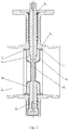
Fig. 1 shows a schematic diagram of a first self-sealing butterfly valve; -
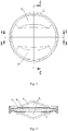
Fig. 2 shows a structural diagram of a of a valve plate; -
Fig. 3 shows a sectional view along an A-A line inFig. 2 ; -
Fig. 4 shows a sectional view along a B-B line inFig. 2 ; -
Fig. 5 shows a sectional view along a C-C line inFig. 2 ; -
Fig. 6 shows a structural diagram of a second self-sealing butterfly valve; -
Fig. 7 shows a D-direction view ofFig. 6 ; -
Fig. 8 shows a structural diagram of the valve plate shown inFig. 6 ; -
Fig. 9 shows a sectional view along an E-E line inFig. 8 ; -
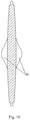
Fig. 10 shows a sectional view along an F-F line inFig. 8 ; -
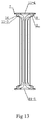
Fig. 11 shows a structural diagram of an elastic sealing ring shown inFig. 6 ; -
Fig. 12 shows a sectional view along a G-G line inFig. 11 ; -
Fig. 13 shows a sectional view along an H-H line inFig. 11 ; -
Fig. 14 shows a structural diagram of a stop ring shown inFig. 6 ; -
Fig. 15 shows a sectional view along an I-I line inFig. 14 ; -
Fig. 16 shows a sectional view along a J-J line inFig. 14 . - With reference to
Fig. 1 , a self-sealing butterfly of a first structure according to the present invention includes a valve body, wherein afluid passage 2 is provided in the valve body, avalve plate 4 of which an outer surface is covered with anelastic sealing layer 3 is provided within thefluid passage 2, theelastic sealing layer 3 is a rubber layer or a polytetrafluoroethylene layer. An upper portion of thevalve plate 4 is dynamically connected with adriving shaft 5 which is rotatably connected to the valve body 1, a lower portion of thevalve plate 4 is rotatably connected with a supportingshaft 6 which is connected to the valve body. Rotation of thedriving shaft 5 may drive rotation of thevalve plate 4 so as to realize opening and closing of the valve. Thedriving shaft 5 and the supportingshaft 6 are assembled with the valve body 1 using a sealing approach. The sealing approach is a common knowledge. For example, thedriving shaft 5 and the supportingshaft 6 may be sealedly fitted with the valve body 1 by sleeving thedraft shaft 5 and the supportingshaft 6 with a sealing ring. - With reference to
Figs. 1-5 , theelastic sealing layer 3 at outer edges of two end faces of thevalve plate 4 axially protrudes outwardly, thereby forming tworing lips 7 attached to an inner wall of thefluid passage 2; and thering lips 7 are gradually thicker from outside to inside, such that inner ring faces 8 of thering lips 7 are inclined faces. An upper inflatedportion 9 for connection with the drivingshaft 5 is provided at an upper portion of thevalve plate 4, a lower inflatedportion 10 for connection with the supportingshaft 6 is provided at a lower portion of thevalve plate 4, a lower surface of the upper inflatedportion 9 and an upper surface of the lower inflatedportion 10 are oppositely arranged, and the area of a lower surface of the upper inflatedportion 9 is greater than an area of the upper surface of the lower inflatedportion 10. - For the above self-sealing butterfly valve, the outer surface of its valve plate is completely covered by the elastic sealing layer. Such a structure is suitable for a small-sized center-line butterfly valve, due to the small size of its valve plate, it is easily completely covered by the elastic sealing layer; however, for a large-sized center-line butterfly valve, due to the relative large size of its valve plate, it is hard to use the elastic sealing layer to completely cover the valve plate. In other words, the above self-sealing butterfly valve of the first structure is hardly made into a large-sized center-line butterfly valve.
- Based on the sealing principle of the self-sealing butterfly valve of the first structure, a self-sealing butterfly valve of a second structure is provided so as to be suitable for manufacturing a large-sized self-sealing butterfly valve. With reference to
Fig. 6 , the self-sealing butterfly valve of the second structure includes a valve body 1, wherein afluid passage 2 is provided in the valve body, avalve plate 4 is provided within thefluid passage 2, an upper portion of thevalve plate 4 is dynamically connected with adriving shaft 5 which is rotatably connected to the valve body 1, a lower portion of thevalve plate 4 is rotatably connected with a supportingshaft 6 which is connected to the valve body. Rotation of the drivingshaft 5 may drive rotation of thevalve plate 4 so as to realize opening and closing of the valve. The drivingshaft 5 and the supportingshaft 6 are assembled with the valve body 1 using a sealing approach. The sealing approach is a common knowledge. For example, the drivingshaft 5 and the supportingshaft 6 may be sealedly fitted with the valve body 1 by sleeving thedraft shaft 5 and the supportingshaft 6 with a sealing ring. Thevalve plate 4 is sleeved with anelastic sealing ring 11 which is capable of enveloping an outer periphery face of thevalve plate 4 and outer edges of two end faces of thevalve plate 4, the two end faces of thevalve plate 4 are respectively connected with astop ring 12 by bolts, inner end faces of the two stop rings 12 are respectively attached with pressure on the two end faces of theelastic sealing ring 12. Outer edges of two end faces of theelastic sealing ring 11 axially protrude outwardly, thereby forming tworing lips 7 attached to an inner wall of thefluid passage 2; and thering lips 7 are gradually thicker from outside to inside, such that inner ring faces 8 of thering lips 7 are an inclined faces. - With reference to
Figs. 6 ,11 ,12 , and13 , theelastic sealing ring 11 includes a loop 11-1 for covering the outer peripheral face of thevalve plate 4, the loop 11-1 has a driving shaft mounting hole 11-4 for the drivingshaft 5 to penetrate and a supporting shaft mounting hole 11-5 for the supporting shaft to penetrate at two opposite sides, two barriers 11-2 are provided at intervals on an inner wall face of the loop 11-1, the two barriers 11-2 and the loop 11-1 form, in concert, a mounting annular groove 11-3, theelastic sealing ring 11 is sleeved on the outer edge of thevalve plate 4 via the mount annular groove 11-3, outer side faces of two barriers form the two end faces of theelastic sealing ring 11, outer edge portions of the outer side faces of the barriers 11-2 axially protrude outwardly to form thering lips 7, andconvex ribs 14 are circularly provided on the two end faces of theelastic sealing ring 11, i.e., on the outer side faces of two barriers 11-2. - With reference to
Figs. 6 ,14 ,15 , and16 , thestop ring 12 is an annular disc. A locatingannular groove 13 is provided on an inner end face of the annular disc, an outer peripheral face of the disc is an inclined face, the disc is circularly arranged with a plurality of bolt penetration holes 15 and a plurality of threadedholes 17, the bolt penetration holes 15 and the threadedholes 17 are alternately provided, i.e., a threadedhole 17 is provided between two adjacent bolt penetration holes 15. For the convenience of molding and for simplifying a manufacturing procedure, thestop ring 12 may be set as a split structure, i.e., the stop ring consists of a plurality of unit sheets, wherein each unit sheet is at least provided with two bolt penetration holes 15 and one threadedhole 17. - With reference to
Fig. 6 andFig. 7 , after theelastic sealing ring 11 is sleeved on thevalve plate 4, the two stop rings 12 are respectively threaded on the two end faces of thevalve plate 4 by being insertedbolts 16 into thebolt penetration hole 15, theconvex ribs 14 are inserted into theannular groove 13, cooperation between theconvex ribs 14 and theannular groove 13 may better fix theelastic sealing ring 11 onto thevalve plate 4. An inner end face of astop ring 12 is attached with pressure on an end face of theelastic sealing ring 11, its outer peripheral face leans on an innerannular face 8 of aring lip 7, an inner end face of theother stop ring 12 is attached with pressure on the other end face of theelastic sealing ring 11, its outer peripheral face leaning on aninner ring face 8 of theother ring lip 7. Within the threadedhole 17 is threaded ascrew 18 abutting against thevalve plate 4. By regulating the tightness of thebolt 16 and thescrew 18, the extrusion degree of thebarrier 12 against theelastic sealing ring 11 may be changed such that the elastic sealing ring is appropriately radially deformed, so as to obtain a desired appropriate interference amount when theelastic sealing ring 11 is assembled with thefluid passage 2. In order to prevent thestop ring 12 from interfering with the elastic deformation of thering lip 7 under the fluid pressure, which may affect the fitting between thering lip 7 and the inner wall of thefluid passage 2 and consequently causes a poor self-sealing effect, the thickness of thestop ring 12 is less than an axial length of thering lip 7. - With reference to
Figs. 8 ,9 , and10 , an upperinflated portion 9 for connection with the drivingshaft 5 is provided at an upper portion of thevalve plate 4, and a lowerinflated portion 10 for connection with the supportingshaft 6 is provided at a lower portion of thevalve plate 4, a lower surface of the upperinflated portion 9 and an upper surface of the lowerinflated portion 10 are oppositely arranged, and an area of the lower surface of the upperinflated portion 9 is greater than an area of the upper surface of the lowerinflated portion 10. A pressure difference exists between the pressure imposed by the fluid on the upperinflated portion 9 and on the lowerinflated portion 10, the pressure difference may effectively counteract the self-weight of the valve plate, such that the valve plate achieves an effect of floating towards the driving shaft direction, resulting in small opening and closing torques of the valve, which not only makes opening and closing of the valve flexible, but also may reduce wear of the elastic sealing ring.
Claims (8)
- A self-sealing butterfly valve, comprising a valve body (1), wherein a fluid passage (2) is provided in the valve body, a valve plate (4) of which an outer surface is covered with an elastic sealing layer (3) is provided within the fluid passage (2), an upper portion of the valve plate (4) is dynamically connected with a driving shaft (5) which is rotatably connected to the valve body (1), a lower portion of the valve plate (4) is rotatably connected with a supporting shaft (6) which is connected to the valve body, and wherein the elastic sealing layer (3) at outer edges of two end faces of the valve plate (4) axially protrudes outwardly, forming two ring lips (7) attached to an inner wall of the fluid passage (2), and the ring lips (7) are gradually thicker from outside to inside, so that inner ring faces (8) of the ring lips (7) are inclined faces, and wherein an upper inflated portion (9) for connection with the driving shaft (5) is provided at the upper portion of the valve plate (4), a lower inflated portion (10) for connection with the supporting shaft (6) is provided at the lower portion of the valve plate (4), a lower surface of the upper inflated portion (9) and an upper surface of the lower inflated portion (10) are oppositely arranged, and an area of the lower surface of the upper inflated portion (9) is greater than an area of the upper surface of the lower inflated portion (10).
- The self-sealing butterfly valve according to claim 1, wherein the elastic sealing layer (3) is a rubber layer or a polytetrafluoroethylene layer.
- A self-sealing butterfly valve, comprising a valve body (1), wherein a fluid passage (2) is provided in the valve body, a valve plate (4) is provided within the fluid passage (2), an upper portion of the valve plate (4) is dynamically connected with a driving shaft (5) which is rotatably connected to the valve body (1), a lower portion of the valve plate (4) is rotatably connected with a supporting shaft (6) which is connected to the valve body, and wherein the valve plate (4) is sleeved with an elastic sealing ring (11) which is capable of enveloping an outer periphery face of the valve plate (4) and outer edges of two end faces of the valve plate (4), outer edges of two end faces of the elastic sealing ring (11) axially protrude outwardly, forming two ring lips (7) attached to an inner wall of the fluid passage (2), and the ring lips (7) are gradually thicker from outside to inside, so that inner ring faces (8) of the ring lips (7) are inclined faces, and wherein an upper inflated portion (9) for connection with the driving shaft (5) is provided at the upper portion of the valve plate (4), a lower inflated portion (10) for connection with the supporting shaft (6) is provided at the lower portion of the valve plate (4), a lower surface of the upper inflated portion (9) and an upper surface of the lower inflated portion (10) are oppositely arranged, and an area of the lower surface of the upper inflated portion (9) is greater than an area of the upper surface of the lower inflated portion (10).
- The self-sealing butterfly valve according to claim 3, wherein the elastic sealing ring (11) comprises a loop (11-1) for covering the outer peripheral face of the valve plate (4), the loop (11-1) has a driving shaft mounting hole (11-4) and a supporting shaft mounting hole (11-5) at two opposite sides, two barriers (11-2) are provided at intervals on an inner wall face of the loop (11-1), the two barriers (11-2) and the loop (11-1) form, in concert, a mounting annular groove (11-3) for sleeving the valve plate (4), outer side faces of two barriers (11-2) form the two end faces of the elastic sealing ring (11), the ring lips (7) are arranged at outer edges of the barriers (11-2), and convex ribs (14) are circularly provided on the two end faces of the elastic sealing ring (11).
- The self-sealing butterfly valve according to claim 4, wherein the two end faces of the valve plate (4) are respectively connected with a stop ring (12), inner end faces of two stop rings (12) are respectively attached with pressure on the two end faces of the elastic sealing ring (11), outer peripheral faces of two stop rings (12) are all inclined faces which may abut against the inner ring faces (8), inner end faces of the stop rings (12) are provided with locating annular grooves (13), and the convex ribs (14) may be inserted into the locating annular grooves (13).
- The self-sealing butterfly valve according to claim 5, wherein the stop rings (12) are circularly arranged with a plurality of bolt penetration holes (15) and a plurality of threaded holes (17), the stop rings (12) are connected to the valve plate (4) by being inserted bolts (16) into the bolt penetration holes (15), and screws (18) abutting against the valve plate (4) are threaded inside the threaded holes (17).
- The self-sealing butterfly valve according to claim 6, wherein the stop ring (12) is a split structure comprising a plurality of unit sheets, wherein each unit sheet is at least provided with two bolt penetration holes (15) and one threaded hole (17).
- The self-sealing butterfly valve according to claim 5, wherein a thickness of the stop ring (12) is less than an axial length of the ring lip (7).
Priority Applications (1)
| Application Number | Priority Date | Filing Date | Title |
|---|---|---|---|
| PL14838495T PL3037696T3 (en) | 2013-08-20 | 2014-08-12 | Self-sealing butterfly valve |
Applications Claiming Priority (2)
| Application Number | Priority Date | Filing Date | Title |
|---|---|---|---|
| CN201310363791.XA CN103438228B (en) | 2013-08-20 | 2013-08-20 | Self-sealing centerline butterfly valve |
| PCT/CN2014/084158 WO2015024468A1 (en) | 2013-08-20 | 2014-08-12 | Self-sealing butterfly valve |
Publications (3)
| Publication Number | Publication Date |
|---|---|
| EP3037696A1 EP3037696A1 (en) | 2016-06-29 |
| EP3037696A4 EP3037696A4 (en) | 2017-04-05 |
| EP3037696B1 true EP3037696B1 (en) | 2019-12-04 |
Family
ID=49691930
Family Applications (1)
| Application Number | Title | Priority Date | Filing Date |
|---|---|---|---|
| EP14838495.1A Active EP3037696B1 (en) | 2013-08-20 | 2014-08-12 | Self-sealing butterfly valve |
Country Status (8)
| Country | Link |
|---|---|
| US (1) | US9995399B2 (en) |
| EP (1) | EP3037696B1 (en) |
| JP (1) | JP6216455B2 (en) |
| KR (1) | KR101814559B1 (en) |
| CN (1) | CN103438228B (en) |
| ES (1) | ES2770586T3 (en) |
| PL (1) | PL3037696T3 (en) |
| WO (1) | WO2015024468A1 (en) |
Families Citing this family (21)
| Publication number | Priority date | Publication date | Assignee | Title |
|---|---|---|---|---|
| CN103438228B (en) | 2013-08-20 | 2015-09-09 | 山东莱德机械有限公司 | Self-sealing centerline butterfly valve |
| JP6634572B2 (en) * | 2016-05-13 | 2020-01-22 | 株式会社テージーケー | Butterfly valve |
| JP6755140B2 (en) * | 2016-07-20 | 2020-09-16 | 旭有機材株式会社 | Butterfly valve |
| CN106090258A (en) * | 2016-08-22 | 2016-11-09 | 苏州科迪流体控制设备有限公司 | A kind of corrosion-resistant butterfly plate for hard seal butterfly valve |
| CN106090257A (en) * | 2016-08-22 | 2016-11-09 | 苏州科迪流体控制设备有限公司 | The butterfly valve turnover panel that a kind of service life is longer |
| CN107420562A (en) * | 2017-04-20 | 2017-12-01 | 天津亚通阀门制造有限公司 | The high-efficiency seal structure of sealed butterfly valve |
| CN107300017B (en) * | 2017-08-27 | 2023-04-07 | 江苏中科机械有限公司 | Three-butterfly-piece elastic sealing switching valve |
| US10969030B2 (en) * | 2017-11-28 | 2021-04-06 | Fisher Controls International Llc | Bushing having a shaft seal |
| CN109681646A (en) * | 2019-02-21 | 2019-04-26 | 江苏神通阀门股份有限公司 | A kind of ultralow temperature butterfly valve |
| EP3722642B1 (en) * | 2019-04-10 | 2022-02-23 | Georg Fischer Rohrleitungssysteme AG | Butterfly valve |
| CN110486485A (en) * | 2019-09-20 | 2019-11-22 | 天津银河阀门有限公司 | A kind of centre-pivoted butterfly valve valve board assembly and centre-pivoted butterfly valve |
| US12092224B2 (en) * | 2019-12-27 | 2024-09-17 | Kitz Corporation | Lined butterfly valve and method for manufacturing lined butterfly valve |
| CN111550562B (en) * | 2020-05-20 | 2021-12-28 | 上海美力德阀门制造有限公司 | Eccentric butterfly valve |
| CN112283364B (en) * | 2020-11-23 | 2025-05-02 | 浙江富技阀门有限公司 | A top-mounted ultra-low temperature butterfly valve that can be maintained online |
| CN113388226B (en) * | 2021-07-14 | 2022-02-18 | 南京厚孚机械科技有限公司 | High-strength impact-resistant polyether-ether-ketone material, preparation method and sealing assembly valve thereof |
| CN115704479A (en) * | 2021-08-03 | 2023-02-17 | 中国石油天然气集团有限公司 | Flue Butterfly Valve with Lower Shafting Support Structure |
| CN113719619A (en) * | 2021-09-29 | 2021-11-30 | 江苏神通阀门股份有限公司 | Nitrogen-filled sealing butterfly valve |
| CN113790278A (en) * | 2021-09-29 | 2021-12-14 | 江苏恒双自控设备制造有限公司 | Leakage-proof self-sealing pneumatic butterfly valve |
| CN113932019A (en) * | 2021-10-16 | 2022-01-14 | 东宝阀门有限公司 | High-pressure self-sealing butterfly valve |
| CN114278741A (en) * | 2022-01-22 | 2022-04-05 | 芜湖市金贸流体科技股份有限公司 | Worm gear transmission wafer type fluorine lining butterfly valve and use method |
| KR102663515B1 (en) * | 2023-05-25 | 2024-05-03 | (주) 디케이금속 | Butterfly valve in which a disc with a molded rubber sealing member is installed |
Family Cites Families (24)
| Publication number | Priority date | Publication date | Assignee | Title |
|---|---|---|---|---|
| FR1339202A (en) * | 1962-11-14 | 1963-10-04 | Betts Machine Company | Butterfly valve |
| US3186682A (en) * | 1963-11-12 | 1965-06-01 | Betts Machine Company | Butterfly valve disc and shaft sealing structure |
| AU5617865A (en) | 1965-03-10 | 1966-09-15 | Betts Machine Company | Butterfly valve |
| JPS4825707Y1 (en) | 1969-05-05 | 1973-07-26 | ||
| US3666233A (en) * | 1970-05-06 | 1972-05-30 | Domer Scaramucci | Butterfly valve assembly having split body |
| US3727883A (en) | 1972-01-26 | 1973-04-17 | Jenkins Bros | Butterfly valve |
| FR2255522B1 (en) | 1973-12-19 | 1982-11-12 | Amri | |
| ES466092A1 (en) | 1977-04-01 | 1979-01-01 | Asahi Organic Chem Ind | Butterfly valve assembly |
| JPS6012762U (en) | 1983-07-05 | 1985-01-28 | 株式會社栗本鐵工所 | Elastic seat ring for butterfly valve |
| JPS60101367A (en) * | 1983-11-08 | 1985-06-05 | Tokyu Car Corp | Butterfly valve |
| CN2201531Y (en) | 1994-09-11 | 1995-06-21 | 刘昌岭 | Full corrosion-resistant butt-clamping butterfly bamper |
| JP3059093B2 (en) * | 1994-12-26 | 2000-07-04 | 日本碍子株式会社 | Butterfly valve for high temperature fluid |
| JP3089211B2 (en) | 1996-05-17 | 2000-09-18 | 株式会社巴技術研究所 | Center type butterfly valve |
| US6135418A (en) * | 1999-02-10 | 2000-10-24 | Eaton Corporation | Low-leakage air valve for variable air intake system |
| DE29920410U1 (en) | 1999-11-19 | 2000-02-03 | Erhard GmbH & Co., 89522 Heidenheim | Flap with pipe adapter |
| ITMC20070062A1 (en) * | 2007-03-28 | 2008-09-29 | O M C E Di Rocchetti Amleto Spa | BUTTERFLY VALVE OR VALVE, IN PARTICULAR FOR TANKS. |
| WO2008136490A1 (en) * | 2007-04-26 | 2008-11-13 | Asahi Organic Chemicals Industry Co., Ltd. | Valve manufacturing method, and valve |
| FR2922984B1 (en) | 2007-10-31 | 2013-09-27 | Saint Gobain Performance Plast | VALVE HAVING RIGID SEAL |
| SE534880C2 (en) * | 2009-03-27 | 2012-01-31 | Inventiair Ab | airflow regulator |
| CN201582409U (en) | 2009-10-29 | 2010-09-15 | 天津银河阀门有限公司 | Spherical sealing butterfly valve provided with valve plate coated with rubber layer |
| CN202091528U (en) | 2011-05-30 | 2011-12-28 | 氟络塞尔特种阀门(苏州)有限公司 | Flexibly sealed butterfly valve |
| CN202901322U (en) * | 2012-11-14 | 2013-04-24 | 宣达实业集团浙江东信特氟隆阀门有限公司 | Lining plastic butterfly valve |
| CN203413138U (en) * | 2013-08-20 | 2014-01-29 | 山东莱德机械有限公司 | Self-sealing center line-type butterfly valve |
| CN103438228B (en) | 2013-08-20 | 2015-09-09 | 山东莱德机械有限公司 | Self-sealing centerline butterfly valve |
-
2013
- 2013-08-20 CN CN201310363791.XA patent/CN103438228B/en active Active
-
2014
- 2014-08-12 US US14/912,707 patent/US9995399B2/en active Active
- 2014-08-12 ES ES14838495T patent/ES2770586T3/en active Active
- 2014-08-12 JP JP2016530342A patent/JP6216455B2/en active Active
- 2014-08-12 KR KR1020167002455A patent/KR101814559B1/en active Active
- 2014-08-12 EP EP14838495.1A patent/EP3037696B1/en active Active
- 2014-08-12 WO PCT/CN2014/084158 patent/WO2015024468A1/en not_active Ceased
- 2014-08-12 PL PL14838495T patent/PL3037696T3/en unknown
Non-Patent Citations (1)
| Title |
|---|
| None * |
Also Published As
| Publication number | Publication date |
|---|---|
| EP3037696A1 (en) | 2016-06-29 |
| EP3037696A4 (en) | 2017-04-05 |
| CN103438228A (en) | 2013-12-11 |
| JP2016525664A (en) | 2016-08-25 |
| US20160201808A1 (en) | 2016-07-14 |
| CN103438228B (en) | 2015-09-09 |
| US9995399B2 (en) | 2018-06-12 |
| ES2770586T3 (en) | 2020-07-02 |
| JP6216455B2 (en) | 2017-10-18 |
| WO2015024468A1 (en) | 2015-02-26 |
| PL3037696T3 (en) | 2020-06-01 |
| KR101814559B1 (en) | 2018-01-04 |
| KR20160023903A (en) | 2016-03-03 |
Similar Documents
| Publication | Publication Date | Title |
|---|---|---|
| US9995399B2 (en) | Self-sealing butterfly valve | |
| CN101429947A (en) | Centrifugal pump, a shaft sleeve and a stationary seal member | |
| CN110319243B (en) | Control valve | |
| CN215763411U (en) | Duplex flow regulating valve | |
| CN216618584U (en) | Double-flow-direction metal hard seal butterfly valve | |
| CN119163666A (en) | A fan-shaped cylinder | |
| CN103047171A (en) | Novel full-function floating throttling device | |
| CN216895867U (en) | Sealed ball valve structure of preventing leaking | |
| CN215257881U (en) | Butterfly valve that leakproofness is strong | |
| CN111853277A (en) | Valve cover and diaphragm sealing device of rotary valve and sealing method thereof | |
| CN214466156U (en) | Butterfly valve with stem correction function | |
| CN1309977C (en) | Butterfly valve | |
| CN219082336U (en) | Inclined valve clack type check valve | |
| CN204267758U (en) | Selfsealings butterfly valve | |
| CN212616474U (en) | Integrated full-meridian eccentric half-ball valve | |
| CN203413138U (en) | Self-sealing center line-type butterfly valve | |
| CN202432007U (en) | Ball valve | |
| CN223203710U (en) | A two-way butterfly valve with elastic hard seal | |
| CN205841792U (en) | A kind of eccentric-butterfly-valve | |
| CN219932981U (en) | Seawater-resistant butterfly valve | |
| CN223782113U (en) | An eccentric hemispherical valve with bidirectional floating seat automatic compensation | |
| KR200344243Y1 (en) | Metal complex seat type butterfly valve | |
| CN205401741U (en) | Eccentric butterfly valve | |
| CN219013357U (en) | Auxiliary sealing device for mechanical sealing of kettle | |
| CN219755485U (en) | Dustproof chemical valve |
Legal Events
| Date | Code | Title | Description |
|---|---|---|---|
| PUAI | Public reference made under article 153(3) epc to a published international application that has entered the european phase |
Free format text: ORIGINAL CODE: 0009012 |
|
| 17P | Request for examination filed |
Effective date: 20160318 |
|
| AK | Designated contracting states |
Kind code of ref document: A1 Designated state(s): AL AT BE BG CH CY CZ DE DK EE ES FI FR GB GR HR HU IE IS IT LI LT LU LV MC MK MT NL NO PL PT RO RS SE SI SK SM TR |
|
| AX | Request for extension of the european patent |
Extension state: BA ME |
|
| DAX | Request for extension of the european patent (deleted) | ||
| A4 | Supplementary search report drawn up and despatched |
Effective date: 20170308 |
|
| RIC1 | Information provided on ipc code assigned before grant |
Ipc: F16K 1/36 20060101ALI20170302BHEP Ipc: F16K 1/226 20060101AFI20170302BHEP Ipc: F16K 1/22 20060101ALI20170302BHEP |
|
| RAP1 | Party data changed (applicant data changed or rights of an application transferred) |
Owner name: AQUA CASTING INC. |
|
| GRAP | Despatch of communication of intention to grant a patent |
Free format text: ORIGINAL CODE: EPIDOSNIGR1 |
|
| STAA | Information on the status of an ep patent application or granted ep patent |
Free format text: STATUS: GRANT OF PATENT IS INTENDED |
|
| INTG | Intention to grant announced |
Effective date: 20190911 |
|
| GRAS | Grant fee paid |
Free format text: ORIGINAL CODE: EPIDOSNIGR3 |
|
| GRAA | (expected) grant |
Free format text: ORIGINAL CODE: 0009210 |
|
| STAA | Information on the status of an ep patent application or granted ep patent |
Free format text: STATUS: THE PATENT HAS BEEN GRANTED |
|
| AK | Designated contracting states |
Kind code of ref document: B1 Designated state(s): AL AT BE BG CH CY CZ DE DK EE ES FI FR GB GR HR HU IE IS IT LI LT LU LV MC MK MT NL NO PL PT RO RS SE SI SK SM TR |
|
| REG | Reference to a national code |
Ref country code: GB Ref legal event code: FG4D |
|
| REG | Reference to a national code |
Ref country code: CH Ref legal event code: EP |
|
| REG | Reference to a national code |
Ref country code: AT Ref legal event code: REF Ref document number: 1209829 Country of ref document: AT Kind code of ref document: T Effective date: 20191215 |
|
| REG | Reference to a national code |
Ref country code: DE Ref legal event code: R096 Ref document number: 602014057965 Country of ref document: DE |
|
| REG | Reference to a national code |
Ref country code: IE Ref legal event code: FG4D |
|
| REG | Reference to a national code |
Ref country code: NL Ref legal event code: MP Effective date: 20191204 |
|
| REG | Reference to a national code |
Ref country code: LT Ref legal event code: MG4D |
|
| PG25 | Lapsed in a contracting state [announced via postgrant information from national office to epo] |
Ref country code: LV Free format text: LAPSE BECAUSE OF FAILURE TO SUBMIT A TRANSLATION OF THE DESCRIPTION OR TO PAY THE FEE WITHIN THE PRESCRIBED TIME-LIMIT Effective date: 20191204 Ref country code: SE Free format text: LAPSE BECAUSE OF FAILURE TO SUBMIT A TRANSLATION OF THE DESCRIPTION OR TO PAY THE FEE WITHIN THE PRESCRIBED TIME-LIMIT Effective date: 20191204 Ref country code: GR Free format text: LAPSE BECAUSE OF FAILURE TO SUBMIT A TRANSLATION OF THE DESCRIPTION OR TO PAY THE FEE WITHIN THE PRESCRIBED TIME-LIMIT Effective date: 20200305 Ref country code: FI Free format text: LAPSE BECAUSE OF FAILURE TO SUBMIT A TRANSLATION OF THE DESCRIPTION OR TO PAY THE FEE WITHIN THE PRESCRIBED TIME-LIMIT Effective date: 20191204 Ref country code: NO Free format text: LAPSE BECAUSE OF FAILURE TO SUBMIT A TRANSLATION OF THE DESCRIPTION OR TO PAY THE FEE WITHIN THE PRESCRIBED TIME-LIMIT Effective date: 20200304 Ref country code: BG Free format text: LAPSE BECAUSE OF FAILURE TO SUBMIT A TRANSLATION OF THE DESCRIPTION OR TO PAY THE FEE WITHIN THE PRESCRIBED TIME-LIMIT Effective date: 20200304 Ref country code: LT Free format text: LAPSE BECAUSE OF FAILURE TO SUBMIT A TRANSLATION OF THE DESCRIPTION OR TO PAY THE FEE WITHIN THE PRESCRIBED TIME-LIMIT Effective date: 20191204 |
|
| PG25 | Lapsed in a contracting state [announced via postgrant information from national office to epo] |
Ref country code: HR Free format text: LAPSE BECAUSE OF FAILURE TO SUBMIT A TRANSLATION OF THE DESCRIPTION OR TO PAY THE FEE WITHIN THE PRESCRIBED TIME-LIMIT Effective date: 20191204 Ref country code: RS Free format text: LAPSE BECAUSE OF FAILURE TO SUBMIT A TRANSLATION OF THE DESCRIPTION OR TO PAY THE FEE WITHIN THE PRESCRIBED TIME-LIMIT Effective date: 20191204 |
|
| PG25 | Lapsed in a contracting state [announced via postgrant information from national office to epo] |
Ref country code: AL Free format text: LAPSE BECAUSE OF FAILURE TO SUBMIT A TRANSLATION OF THE DESCRIPTION OR TO PAY THE FEE WITHIN THE PRESCRIBED TIME-LIMIT Effective date: 20191204 |
|
| REG | Reference to a national code |
Ref country code: ES Ref legal event code: FG2A Ref document number: 2770586 Country of ref document: ES Kind code of ref document: T3 Effective date: 20200702 |
|
| PG25 | Lapsed in a contracting state [announced via postgrant information from national office to epo] |
Ref country code: RO Free format text: LAPSE BECAUSE OF FAILURE TO SUBMIT A TRANSLATION OF THE DESCRIPTION OR TO PAY THE FEE WITHIN THE PRESCRIBED TIME-LIMIT Effective date: 20191204 Ref country code: CZ Free format text: LAPSE BECAUSE OF FAILURE TO SUBMIT A TRANSLATION OF THE DESCRIPTION OR TO PAY THE FEE WITHIN THE PRESCRIBED TIME-LIMIT Effective date: 20191204 Ref country code: NL Free format text: LAPSE BECAUSE OF FAILURE TO SUBMIT A TRANSLATION OF THE DESCRIPTION OR TO PAY THE FEE WITHIN THE PRESCRIBED TIME-LIMIT Effective date: 20191204 Ref country code: EE Free format text: LAPSE BECAUSE OF FAILURE TO SUBMIT A TRANSLATION OF THE DESCRIPTION OR TO PAY THE FEE WITHIN THE PRESCRIBED TIME-LIMIT Effective date: 20191204 Ref country code: PT Free format text: LAPSE BECAUSE OF FAILURE TO SUBMIT A TRANSLATION OF THE DESCRIPTION OR TO PAY THE FEE WITHIN THE PRESCRIBED TIME-LIMIT Effective date: 20200429 |
|
| PG25 | Lapsed in a contracting state [announced via postgrant information from national office to epo] |
Ref country code: SM Free format text: LAPSE BECAUSE OF FAILURE TO SUBMIT A TRANSLATION OF THE DESCRIPTION OR TO PAY THE FEE WITHIN THE PRESCRIBED TIME-LIMIT Effective date: 20191204 Ref country code: SK Free format text: LAPSE BECAUSE OF FAILURE TO SUBMIT A TRANSLATION OF THE DESCRIPTION OR TO PAY THE FEE WITHIN THE PRESCRIBED TIME-LIMIT Effective date: 20191204 Ref country code: IS Free format text: LAPSE BECAUSE OF FAILURE TO SUBMIT A TRANSLATION OF THE DESCRIPTION OR TO PAY THE FEE WITHIN THE PRESCRIBED TIME-LIMIT Effective date: 20200404 |
|
| REG | Reference to a national code |
Ref country code: DE Ref legal event code: R097 Ref document number: 602014057965 Country of ref document: DE |
|
| REG | Reference to a national code |
Ref country code: AT Ref legal event code: MK05 Ref document number: 1209829 Country of ref document: AT Kind code of ref document: T Effective date: 20191204 |
|
| PLBE | No opposition filed within time limit |
Free format text: ORIGINAL CODE: 0009261 |
|
| STAA | Information on the status of an ep patent application or granted ep patent |
Free format text: STATUS: NO OPPOSITION FILED WITHIN TIME LIMIT |
|
| PG25 | Lapsed in a contracting state [announced via postgrant information from national office to epo] |
Ref country code: DK Free format text: LAPSE BECAUSE OF FAILURE TO SUBMIT A TRANSLATION OF THE DESCRIPTION OR TO PAY THE FEE WITHIN THE PRESCRIBED TIME-LIMIT Effective date: 20191204 |
|
| 26N | No opposition filed |
Effective date: 20200907 |
|
| PG25 | Lapsed in a contracting state [announced via postgrant information from national office to epo] |
Ref country code: AT Free format text: LAPSE BECAUSE OF FAILURE TO SUBMIT A TRANSLATION OF THE DESCRIPTION OR TO PAY THE FEE WITHIN THE PRESCRIBED TIME-LIMIT Effective date: 20191204 Ref country code: SI Free format text: LAPSE BECAUSE OF FAILURE TO SUBMIT A TRANSLATION OF THE DESCRIPTION OR TO PAY THE FEE WITHIN THE PRESCRIBED TIME-LIMIT Effective date: 20191204 |
|
| PG25 | Lapsed in a contracting state [announced via postgrant information from national office to epo] |
Ref country code: MC Free format text: LAPSE BECAUSE OF FAILURE TO SUBMIT A TRANSLATION OF THE DESCRIPTION OR TO PAY THE FEE WITHIN THE PRESCRIBED TIME-LIMIT Effective date: 20191204 |
|
| REG | Reference to a national code |
Ref country code: CH Ref legal event code: PL |
|
| PG25 | Lapsed in a contracting state [announced via postgrant information from national office to epo] |
Ref country code: CH Free format text: LAPSE BECAUSE OF NON-PAYMENT OF DUE FEES Effective date: 20200831 Ref country code: LI Free format text: LAPSE BECAUSE OF NON-PAYMENT OF DUE FEES Effective date: 20200831 Ref country code: LU Free format text: LAPSE BECAUSE OF NON-PAYMENT OF DUE FEES Effective date: 20200812 |
|
| REG | Reference to a national code |
Ref country code: BE Ref legal event code: MM Effective date: 20200831 |
|
| PG25 | Lapsed in a contracting state [announced via postgrant information from national office to epo] |
Ref country code: BE Free format text: LAPSE BECAUSE OF NON-PAYMENT OF DUE FEES Effective date: 20200831 Ref country code: IE Free format text: LAPSE BECAUSE OF NON-PAYMENT OF DUE FEES Effective date: 20200812 |
|
| PG25 | Lapsed in a contracting state [announced via postgrant information from national office to epo] |
Ref country code: TR Free format text: LAPSE BECAUSE OF FAILURE TO SUBMIT A TRANSLATION OF THE DESCRIPTION OR TO PAY THE FEE WITHIN THE PRESCRIBED TIME-LIMIT Effective date: 20191204 Ref country code: MT Free format text: LAPSE BECAUSE OF FAILURE TO SUBMIT A TRANSLATION OF THE DESCRIPTION OR TO PAY THE FEE WITHIN THE PRESCRIBED TIME-LIMIT Effective date: 20191204 Ref country code: CY Free format text: LAPSE BECAUSE OF FAILURE TO SUBMIT A TRANSLATION OF THE DESCRIPTION OR TO PAY THE FEE WITHIN THE PRESCRIBED TIME-LIMIT Effective date: 20191204 |
|
| PG25 | Lapsed in a contracting state [announced via postgrant information from national office to epo] |
Ref country code: MK Free format text: LAPSE BECAUSE OF FAILURE TO SUBMIT A TRANSLATION OF THE DESCRIPTION OR TO PAY THE FEE WITHIN THE PRESCRIBED TIME-LIMIT Effective date: 20191204 |
|
| PGFP | Annual fee paid to national office [announced via postgrant information from national office to epo] |
Ref country code: GB Payment date: 20250625 Year of fee payment: 12 |
|
| PGFP | Annual fee paid to national office [announced via postgrant information from national office to epo] |
Ref country code: FR Payment date: 20250619 Year of fee payment: 12 |
|
| PGFP | Annual fee paid to national office [announced via postgrant information from national office to epo] |
Ref country code: ES Payment date: 20250917 Year of fee payment: 12 |
|
| PGFP | Annual fee paid to national office [announced via postgrant information from national office to epo] |
Ref country code: DE Payment date: 20250819 Year of fee payment: 12 |
|
| PGFP | Annual fee paid to national office [announced via postgrant information from national office to epo] |
Ref country code: IT Payment date: 20250829 Year of fee payment: 12 Ref country code: PL Payment date: 20250804 Year of fee payment: 12 |