EP3037159A1 - Device for aerating wine - Google Patents
Device for aerating wine Download PDFInfo
- Publication number
- EP3037159A1 EP3037159A1 EP15003620.0A EP15003620A EP3037159A1 EP 3037159 A1 EP3037159 A1 EP 3037159A1 EP 15003620 A EP15003620 A EP 15003620A EP 3037159 A1 EP3037159 A1 EP 3037159A1
- Authority
- EP
- European Patent Office
- Prior art keywords
- lance
- body member
- valve
- wine
- gas
- Prior art date
- Legal status (The legal status is an assumption and is not a legal conclusion. Google has not performed a legal analysis and makes no representation as to the accuracy of the status listed.)
- Withdrawn
Links
- 238000003780 insertion Methods 0.000 claims abstract description 3
- 230000037431 insertion Effects 0.000 claims abstract description 3
- 238000011144 upstream manufacturing Methods 0.000 claims description 8
- 239000007789 gas Substances 0.000 description 35
- QVGXLLKOCUKJST-UHFFFAOYSA-N atomic oxygen Chemical compound [O] QVGXLLKOCUKJST-UHFFFAOYSA-N 0.000 description 2
- 239000011521 glass Substances 0.000 description 2
- 230000005484 gravity Effects 0.000 description 2
- 239000001301 oxygen Substances 0.000 description 2
- 229910052760 oxygen Inorganic materials 0.000 description 2
- 229910001220 stainless steel Inorganic materials 0.000 description 2
- 239000010935 stainless steel Substances 0.000 description 2
- 229910001369 Brass Inorganic materials 0.000 description 1
- 230000000903 blocking effect Effects 0.000 description 1
- 239000010951 brass Substances 0.000 description 1
- 230000001419 dependent effect Effects 0.000 description 1
- 230000000694 effects Effects 0.000 description 1
- 239000012530 fluid Substances 0.000 description 1
- 238000000034 method Methods 0.000 description 1
- 230000001706 oxygenating effect Effects 0.000 description 1
- 238000007789 sealing Methods 0.000 description 1
Images


Classifications
-
- B—PERFORMING OPERATIONS; TRANSPORTING
- B01—PHYSICAL OR CHEMICAL PROCESSES OR APPARATUS IN GENERAL
- B01F—MIXING, e.g. DISSOLVING, EMULSIFYING OR DISPERSING
- B01F23/00—Mixing according to the phases to be mixed, e.g. dispersing or emulsifying
- B01F23/20—Mixing gases with liquids
- B01F23/23—Mixing gases with liquids by introducing gases into liquid media, e.g. for producing aerated liquids
- B01F23/236—Mixing gases with liquids by introducing gases into liquid media, e.g. for producing aerated liquids specially adapted for aerating or carbonating beverages
- B01F23/2361—Mixing gases with liquids by introducing gases into liquid media, e.g. for producing aerated liquids specially adapted for aerating or carbonating beverages within small containers, e.g. within bottles
- B01F23/23611—Portable appliances comprising a gas cartridge
-
- B—PERFORMING OPERATIONS; TRANSPORTING
- B01—PHYSICAL OR CHEMICAL PROCESSES OR APPARATUS IN GENERAL
- B01F—MIXING, e.g. DISSOLVING, EMULSIFYING OR DISPERSING
- B01F33/00—Other mixers; Mixing plants; Combinations of mixers
- B01F33/50—Movable or transportable mixing devices or plants
- B01F33/501—Movable mixing devices, i.e. readily shifted or displaced from one place to another, e.g. portable during use
- B01F33/5011—Movable mixing devices, i.e. readily shifted or displaced from one place to another, e.g. portable during use portable during use, e.g. hand-held
-
- B—PERFORMING OPERATIONS; TRANSPORTING
- B01—PHYSICAL OR CHEMICAL PROCESSES OR APPARATUS IN GENERAL
- B01F—MIXING, e.g. DISSOLVING, EMULSIFYING OR DISPERSING
- B01F2101/00—Mixing characterised by the nature of the mixed materials or by the application field
- B01F2101/06—Mixing of food ingredients
- B01F2101/16—Mixing wine or other alcoholic beverages; Mixing ingredients thereof
- B01F2101/17—Aeration of wine
Definitions
- the present invention relates to a device for aerating or oxygenating wine.
- Adding controlled amounts of oxygen to wine, or aerating the wine is known to improve its taste.
- wine is aerated before use via a decanter or carafe.
- wine can also be aerated using a venturi type system whereby the wine is poured from the bottle into an intermediary vessel above the wine glass, and the wine then aerated via the venturi effect as it passes from the intermediary vessel to the wine glass.
- a venturi type system whereby the wine is poured from the bottle into an intermediary vessel above the wine glass, and the wine then aerated via the venturi effect as it passes from the intermediary vessel to the wine glass.
- Wine aerating devices comprising a container for pressurized oxygen containing gas, such as air, a body member for holding the gas container, and a lance member, via which gas from the gas container can be diffused into a wine, are known.
- the invention attempts to simplify the design of a wine aerating device.
- the wine aerating device comprises a container containing pressurized gas, a body member and a lance member for inserting into wine to be aerated, the container, the body member and the lance member being engageable in such a way as to provide a passage for passing pressurized gas in a downstream direction from the container through the body member into the lance member, the lance member being engageable with the body member by means of insertion into the body member, the body member being provided with a valve, arranged such that in case the lance member is disengaged from the body member the valve defines a closed position preventing flow of gas through the body member, and in case the lance member engages the body member, to be pushed into an open position, the open position allowing flow of gas through the body member into the lance member, wherein there is provided a bayonet closure for engagement of the lance member with the body member.
- a bayonet closure provides a simple and robust engagement for the lance member with respect to the body member.
- the arrangement of the valve according to the present invention provides a tight seal, preventing unwanted escape of gas from the body member in case no lance member is engaged with the body member. It also allows flow of gas through the body member and the lance in case of engagement of a lance with the body member, at the same time preventing gas escaping through any other paths within the body member.
- downstream direction refers to the airflow of gas from the gas container (cylinder) through the body member to the lance.
- upstream direction is the opposite direction.
- the body member is arranged downstream of the gas container, and the lance downstream of the body member.
- air and gas are used synonymously throughout the specification.
- the valve is arranged to be pushed from the closed position into the open position by the upstream end of the lance being inserted into the body member. This provides a simple and robust engagement and disengagement of the lance with respect to the body member, at the same time ensuring a tight seal in the closed as well as the opened position.
- At least one annular seal is provided in the passage within the body member, which is arranged for engagement with the valve in the closed position, and with the lance member in the open position.
- the valve is provided as a spring biased valve comprising a valve body and a spring engaging the valve body.
- a spring biased valve By means of such a spring biased valve, it can be easily ensured that, in case of disengagement of a lance with respect to the body member, i.e.no lance being connected to the member, the valve housing is urged into the closed position by means of the spring.
- the container, especially a cylinder, the tube,and the lance may be co-axial to provide an easily determinable centre of gravity for the device. This axis may extend through the neck of the wine bottle when the device is placed thereon. With this arrangement, when the device is placed on the bottle, the device's centre of gravity is more likely to act through the neck of the wine, ensuring that the device is stable on the bottle.
- pressurized gas source any form of pressurized gas source may be used.
- the gas container described above may be single use, replaceable or refillable.
- the device may be manufactured and distributed with or without a pressurized gas container.
- the aerating device comprises a body member 10 for holding a gas container (cylinder) (not shown) and a lance member 16 comprising a tube 17 and a diffusor body 18.
- the diffusor body 18 is arranged downstream of the tube 17, the tube 17 downstream of body member 10.
- the aerating device is arranged to engage with the neck of a wine bottle, which has e. g. a fluid content of 75 cl, not shown, via an interface 12.
- the interface also connects the body member 10 to the tube 17 of lance member 16.
- the interface 12 forms a conical shape, which is dimensioned to fit inside or on the neck of a wine bottle.
- Figures 2 and 3 show a sectional view through interface 12, i.e.the section of the body member 10, where tube 17 of lance member 16 engages the body member 10.
- tube 17 of lance member 16 engages the body member 10.
- the body member 10 is provided with a cylindrical bore 20 extending along its central axis A which is provided in a stepped manner in order to hold various components, as will be further explained in the following. Also, the cylindrical bore forms part of a passage between a gas container (not shown) and the lance 16, for passing pressurized gas form the gas cylinder through the body member to the lance member 16.
- Valve member 22 comprises a valve body 24 and a spring element 26.
- the valve body comprises a first portion 24a with a first diameter, which essentially corresponds to the diameter of the bore 20. It comprises a second portion 24b with a second diameter, which is smaller than the first diameter and a third portion 24c, with a third diameter, which can either be smaller or the same size as the second diameter.
- the spring element 26 biases the valve housing 24 to the right, i.e. towards the downstream side of body element 10 as symbolised by arrow P, so that the second section 24b of valve body engages an O-ring acting as an annular seal, preventing any gas upstream of valve element 22 from escaping through the downstream side of housing member 10, i.e. the downstream end of bore 20.
- the spring 26 is in an expanded state.
- a lance member 16 is inserted through the downstream opening of bore 20.
- the upstream end of lance member 16 has pushed the valve body 24 out of engagement with O-ring 30 by compressing spring 26, at the same time providing an engagement between an upstream end section 16a of the lance 16 with the O-ring 30.
- valve body 24 has been pushed to the left, i.e. in the upstream direction of bore 20, and spring 26 is in a compressed state.
- the thus provided axial position of lance member 16 can be secured by turning lance member 16 by about 90° about central axis A, thus providing a bayonet closure between radial extensions 16b of the lance member 16 and a corresponding recess 20a in housing member 10, recess 20a forming radial extension of bore 20.
- the spring is secured in its compressed state.
- the diameter of the end portion 16a of lance member 16 expediently corresponds to the diameter of the second portion 24b of the valve body member.
- a gas flow from the upstream side of valve element 22 to the downstream side of valve element 22 into a passage 36 within of lance 16 can be achieved by providing axially extending openings in the circumferential wall 25 of valve body 24 (not shown in figure 3 ).
- pressurized air can enter into a space 32 between the second portion 24b of the valve body 24 and a wall 20b of bore 20, from where it can pass into the central passage 36 of lance 16 by means of radially extending openings, provided in third position 24c of valve body 24 (also not shown).
- the seal provided by the engagement of lance 16 and O-ring 30 ensures that no gas can escape through any other passage, for example any gaps between the outer circumference of lance member 16 and bore 20.
- a (not shown) actuating mechanism provided for example between the gas container and the body element 10, it can be ensured that gas can not escape from the gas container, even if lance member 16 engages body member 10 in the way shown in figure 3 .
- valve housing 24 is urged back into its original position, as shown in figure 2 , by spring 26.
- the reference numbers are same as they in the figures above.
- the additional reference number in figures 4 and 5 compared with figures 1 to 3 are another O-ring 31 and a gas channel C.
- the lance member 16 in figures 4 and 5 has a diameter at the end part as same as it of other parts, while in figures 1 to 3 because of the size of O-ring 30 the diameter of end part of the lance 16 is smaller than it of other parts.
- the additional O-ring 31 makes the sealing more effective and the gas channel C can be configured by a gas channel slot which releases the gas from the gas container (not shown) through body member 10 into lance member 16.
- the valve housing 24 is expediently made of stainless steel or brass.
- the lance 16 is preferably made of stainless steel.
Landscapes
- Chemical & Material Sciences (AREA)
- Chemical Kinetics & Catalysis (AREA)
- Devices For Dispensing Beverages (AREA)
Abstract
Description
- The present invention relates to a device for aerating or oxygenating wine.
- Adding controlled amounts of oxygen to wine, or aerating the wine, is known to improve its taste. Typically, wine is aerated before use via a decanter or carafe. In a recent development wine can also be aerated using a venturi type system whereby the wine is poured from the bottle into an intermediary vessel above the wine glass, and the wine then aerated via the venturi effect as it passes from the intermediary vessel to the wine glass. Both of these aerating methods however are limited in terms of the rate of which air can be introduced into the wine.
- Wine aerating devices comprising a container for pressurized oxygen containing gas, such as air, a body member for holding the gas container, and a lance member, via which gas from the gas container can be diffused into a wine, are known.
- The invention attempts to simplify the design of a wine aerating device.
- This object is achieved with a wine aerating device according to claim 1.
- The wine aerating device according to the invention comprises a container containing pressurized gas, a body member and a lance member for inserting into wine to be aerated, the container, the body member and the lance member being engageable in such a way as to provide a passage for passing pressurized gas in a downstream direction from the container through the body member into the lance member, the lance member being engageable with the body member by means of insertion into the body member, the body member being provided with a valve, arranged such that in case the lance member is disengaged from the body member the valve defines a closed position preventing flow of gas through the body member, and in case the lance member engages the body member, to be pushed into an open position, the open position allowing flow of gas through the body member into the lance member, wherein there is provided a bayonet closure for engagement of the lance member with the body member. Such a bayonet closure provides a simple and robust engagement for the lance member with respect to the body member..
- The arrangement of the valve according to the present invention provides a tight seal, preventing unwanted escape of gas from the body member in case no lance member is engaged with the body member. It also allows flow of gas through the body member and the lance in case of engagement of a lance with the body member, at the same time preventing gas escaping through any other paths within the body member.
- Advantageous embodiments of the invention are the subject matters of the dependent claims. Be it noted in this connection that the term "downstream direction" as used in this specification refers to the airflow of gas from the gas container (cylinder) through the body member to the lance. The "upstream direction" is the opposite direction. Thus, the body member is arranged downstream of the gas container, and the lance downstream of the body member. The terms "air" and "gas" are used synonymously throughout the specification.
- Advantageously, the valve is arranged to be pushed from the closed position into the open position by the upstream end of the lance being inserted into the body member. This provides a simple and robust engagement and disengagement of the lance with respect to the body member, at the same time ensuring a tight seal in the closed as well as the opened position.
- Advantageously, at least one annular seal is provided in the passage within the body member, which is arranged for engagement with the valve in the closed position, and with the lance member in the open position. By appropriate design of such an annular seal, it can be ensured that in the closed position the annular seal tightly surrounds the valve, thus blocking the passage and preventing any escape of gas from the body member. Also, in the open position, the annular seal can form a tight seal with the lance member, ensuring that escape of gas will only occur through a central passage within the lance member.
- Advantageously, the valve is provided as a spring biased valve comprising a valve body and a spring engaging the valve body. By means of such a spring biased valve, it can be easily ensured that, in case of disengagement of a lance with respect to the body member, i.e.no lance being connected to the member, the valve housing is urged into the closed position by means of the spring.
The container, especially a cylinder, the tube,and the lance may be co-axial to provide an easily determinable centre of gravity for the device. This axis may extend through the neck of the wine bottle when the device is placed thereon. With this arrangement, when the device is placed on the bottle, the device's centre of gravity is more likely to act through the neck of the wine, ensuring that the device is stable on the bottle. - It will also be appreciated that any form of pressurized gas source may be used. Indeed, the gas container described above may be single use, replaceable or refillable. The device may be manufactured and distributed with or without a pressurized gas container.
- It should be noted that the previously mentioned features and the features to be further described in the following are usable not only in the respectively indicated combination, but also in further combinations or taken alone, without departing from the scope of the present invention.
- The present invention will now be further described with reference to the following figures, in which:
-
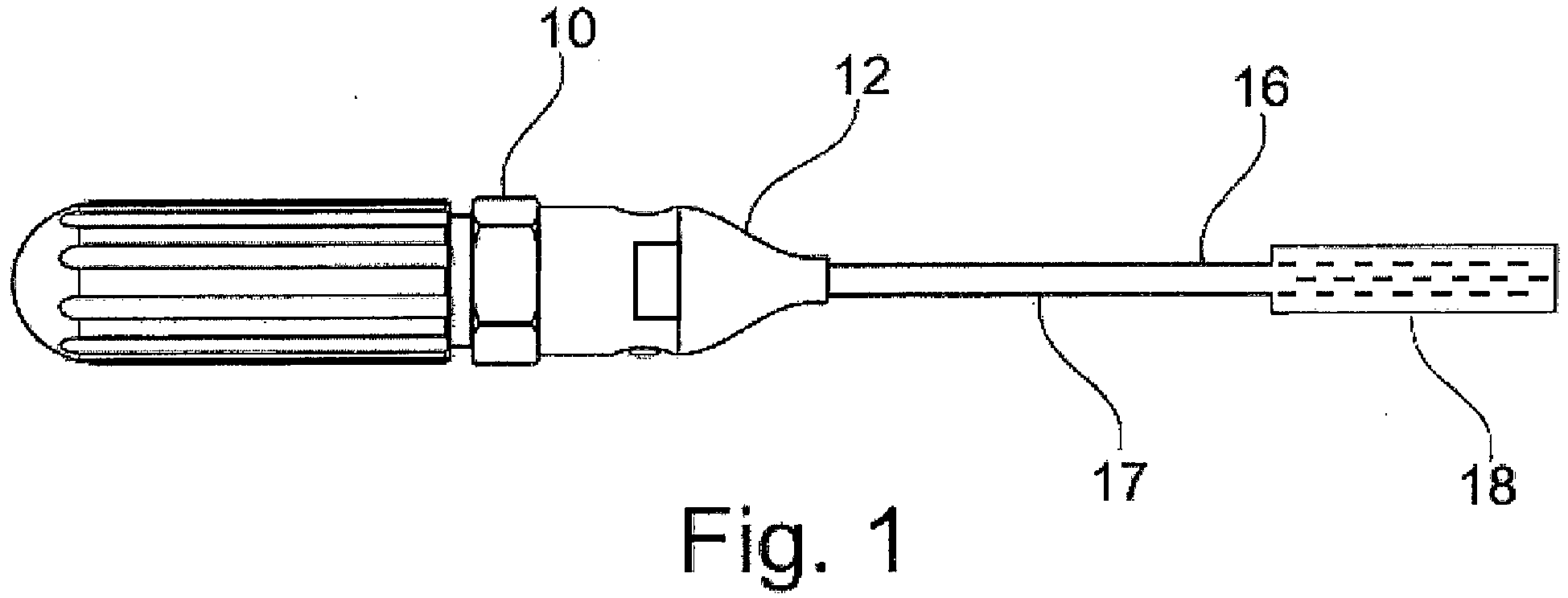
Figure 1 shows a plan view of wine aerating device according to an embodiment of an invention, -
Figure 2 shows a partial sectional view of a preferred embodiment of a aerated wine aerating device according to the invention in a first mode of operation, and -
Figure 3 shows a corresponding view of the wine aerating device according tofigure 2 in a second mode of operation. -
Figure 4 shows a partial sectional view of wine aerating device according to another embodiment of the invention in case the lance member is disengaged from the body member -
Figure 5 shows a corresponding view of the wine aerating device according tofigure 4 in case that the lance member engages the body member - The aerating device comprises a
body member 10 for holding a gas container (cylinder) (not shown) and alance member 16 comprising atube 17 and adiffusor body 18. Thediffusor body 18 is arranged downstream of thetube 17, thetube 17 downstream ofbody member 10. In use, the aerating device is arranged to engage with the neck of a wine bottle, which has e. g. a fluid content of 75 cl, not shown, via aninterface 12. The interface also connects thebody member 10 to thetube 17 oflance member 16. Theinterface 12 forms a conical shape, which is dimensioned to fit inside or on the neck of a wine bottle. -
Figures 2 and3 show a sectional view throughinterface 12, i.e.the section of thebody member 10, wheretube 17 oflance member 16 engages thebody member 10. For ease of reference, the following description will refer only to lancemember 16. - The
body member 10 is provided with acylindrical bore 20 extending along its central axis A which is provided in a stepped manner in order to hold various components, as will be further explained in the following. Also, the cylindrical bore forms part of a passage between a gas container (not shown) and thelance 16, for passing pressurized gas form the gas cylinder through the body member to thelance member 16. - In
bore 20, there is provided avalve member 22. Valvemember 22 comprises avalve body 24 and aspring element 26. The valve body comprises afirst portion 24a with a first diameter, which essentially corresponds to the diameter of thebore 20. It comprises asecond portion 24b with a second diameter, which is smaller than the first diameter and athird portion 24c, with a third diameter, which can either be smaller or the same size as the second diameter. - In the closed position shown in
figure 2 , thespring element 26 biases thevalve housing 24 to the right, i.e. towards the downstream side ofbody element 10 as symbolised by arrow P, so that thesecond section 24b of valve body engages an O-ring acting as an annular seal, preventing any gas upstream ofvalve element 22 from escaping through the downstream side ofhousing member 10, i.e. the downstream end ofbore 20. In this mode of operation, thespring 26 is in an expanded state. - In
figure 3 , alance member 16 is inserted through the downstream opening ofbore 20. As can be seen infigure 3 , the upstream end oflance member 16 has pushed thevalve body 24 out of engagement with O-ring 30 by compressingspring 26, at the same time providing an engagement between anupstream end section 16a of thelance 16 with the O-ring 30. - In this position,
valve body 24 has been pushed to the left, i.e. in the upstream direction ofbore 20, andspring 26 is in a compressed state. The thus provided axial position oflance member 16 can be secured by turninglance member 16 by about 90° about central axis A, thus providing a bayonet closure between radial extensions 16b of thelance member 16 and acorresponding recess 20a inhousing member 10, recess 20a forming radial extension ofbore 20. In this position oflance 16, the spring is secured in its compressed state. - The diameter of the
end portion 16a oflance member 16 expediently corresponds to the diameter of thesecond portion 24b of the valve body member.. - In this position, a gas flow from the upstream side of
valve element 22 to the downstream side ofvalve element 22 into apassage 36 within of lance 16 (represented by arrow p) can be achieved by providing axially extending openings in thecircumferential wall 25 of valve body 24 (not shown infigure 3 ). By means of such openings pressurized air can enter into aspace 32 between thesecond portion 24b of thevalve body 24 and awall 20b ofbore 20, from where it can pass into thecentral passage 36 oflance 16 by means of radially extending openings, provided inthird position 24c of valve body 24 (also not shown). - At the same time, the seal provided by the engagement of
lance 16 and O-ring 30 ensures that no gas can escape through any other passage, for example any gaps between the outer circumference oflance member 16 and bore 20. By means of a (not shown) actuating mechanism, provided for example between the gas container and thebody element 10, it can be ensured that gas can not escape from the gas container, even iflance member 16 engagesbody member 10 in the way shown infigure 3 . - After usage, the state as shown in
figure 2 can be re-established by disengaginglance 16 by a corresponding reverse 90° turn of thelance 16 and pulling it out ofbore 20. Thus,valve housing 24 is urged back into its original position, as shown infigure 2 , byspring 26. - In
figures 4 and5 , the reference numbers are same as they in the figures above. The additional reference number infigures 4 and5 compared withfigures 1 to 3 are another O-ring 31 and a gas channel C. Moreover, thelance member 16 infigures 4 and5 has a diameter at the end part as same as it of other parts, while infigures 1 to 3 because of the size of O-ring 30 the diameter of end part of thelance 16 is smaller than it of other parts. The additional O-ring 31 makes the sealing more effective and the gas channel C can be configured by a gas channel slot which releases the gas from the gas container (not shown) throughbody member 10 intolance member 16. - The
valve housing 24 is expediently made of stainless steel or brass. Thelance 16 is preferably made of stainless steel.
Claims (4)
- Wine aerating device comprising a container containing pressurized gas, a body member (10) and a lance member (16) for inserting into wine to be aerated, the container, the body member and the lance member being engageable in such a way as to provide a passage for passing pressurized gas in a downstream direction from the container (3) through the body member (10) into the lance member (16), the lance member (16) being engageable with the body member (10) by means of insertion into the body member, the body member (10) being provided with a valve (22), the valve (22) being arranged such that in case the lance member (16) is disengaged from the body member (10), it defines a closed position preventing flow of gas through the body member (10), and in case the lance member (16) engages the body member, it is pushed into an open position, the open position allowing flow of gas through the body member (10) into the lance member (16), wherein there is provided a bayonet closure (16b, 20a) for engagement of the lance member (16) with the body member (10).
- Wine aerating device according to claim 1, wherein the valve (22) is arranged to be pushed from the closed position into the open position by an upstream end of the lance member (16) being inserted into a bore (20) provided in the body member (10) from the downstream end of the body member (10).
- Wine aerating device according to claim 1 or claim 2, wherein at least one annular seal (30, 31) is provided in bore 20, for engagement with the valve (22) in the closed position, and with the lance member (16) in the open position.
- Wine aerating device according to any one of the preceding claims, wherein the valve (22) is provided as a spring biased valve (22, 24, 26).
Priority Applications (2)
| Application Number | Priority Date | Filing Date | Title |
|---|---|---|---|
| EP15003620.0A EP3037159A1 (en) | 2014-12-23 | 2015-12-18 | Device for aerating wine |
| US15/062,234 US20160184781A1 (en) | 2014-12-23 | 2016-03-07 | Device for aerating wine |
Applications Claiming Priority (2)
| Application Number | Priority Date | Filing Date | Title |
|---|---|---|---|
| EP14004380 | 2014-12-23 | ||
| EP15003620.0A EP3037159A1 (en) | 2014-12-23 | 2015-12-18 | Device for aerating wine |
Publications (1)
| Publication Number | Publication Date |
|---|---|
| EP3037159A1 true EP3037159A1 (en) | 2016-06-29 |
Family
ID=52292592
Family Applications (1)
| Application Number | Title | Priority Date | Filing Date |
|---|---|---|---|
| EP15003620.0A Withdrawn EP3037159A1 (en) | 2014-12-23 | 2015-12-18 | Device for aerating wine |
Country Status (1)
| Country | Link |
|---|---|
| EP (1) | EP3037159A1 (en) |
Citations (4)
| Publication number | Priority date | Publication date | Assignee | Title |
|---|---|---|---|---|
| US2072629A (en) * | 1934-01-15 | 1937-03-02 | Fernholz Ernst | Coupling device for carbonators |
| US20110297006A1 (en) * | 2010-04-21 | 2011-12-08 | Tfb Consultants, Ltd | Liquid Decanting Method and Apparatus |
| US20130153685A1 (en) * | 2011-12-16 | 2013-06-20 | Drobot Michael J. | Combination aerator, pourer, preserver, and stopper for a container |
| US8561970B1 (en) * | 2013-01-23 | 2013-10-22 | Brookstone Purchasing, Inc. | Aeration system |
-
2015
- 2015-12-18 EP EP15003620.0A patent/EP3037159A1/en not_active Withdrawn
Patent Citations (4)
| Publication number | Priority date | Publication date | Assignee | Title |
|---|---|---|---|---|
| US2072629A (en) * | 1934-01-15 | 1937-03-02 | Fernholz Ernst | Coupling device for carbonators |
| US20110297006A1 (en) * | 2010-04-21 | 2011-12-08 | Tfb Consultants, Ltd | Liquid Decanting Method and Apparatus |
| US20130153685A1 (en) * | 2011-12-16 | 2013-06-20 | Drobot Michael J. | Combination aerator, pourer, preserver, and stopper for a container |
| US8561970B1 (en) * | 2013-01-23 | 2013-10-22 | Brookstone Purchasing, Inc. | Aeration system |
Similar Documents
| Publication | Publication Date | Title |
|---|---|---|
| ES2240928T3 (en) | QUICK FITTING FOR THE MOVING CONNECTION OF TWO DRIVES. | |
| US996588A (en) | Combined union and check valve. | |
| US20140178549A1 (en) | Resealable spout for selectively accessing coconut water within a coconut | |
| IL182555A0 (en) | Tap for dispensing liquids from vessels | |
| EP3037730A3 (en) | Eductor fuel purging system for a turbomachine | |
| WO2012121768A3 (en) | Sample containment apparatus, systems, and methods | |
| WO2005021394A3 (en) | Dispensing device comprising a sealing plug and locking ring with bayonet connecting means | |
| JPH09177736A (en) | Tube coupling | |
| US8561632B2 (en) | Quick-acting valve having metering relief | |
| EP3037712A1 (en) | Safety sealing connecting device for gas cylinder | |
| US20240418475A1 (en) | Pressurized gas vessel and piercing mechanism | |
| US20160184781A1 (en) | Device for aerating wine | |
| US7856976B2 (en) | Gas mask with drinking device | |
| US4638835A (en) | Automatic overflow control apparatus for the pipeline passage | |
| US9764637B2 (en) | Fuel tank mounted refueling device | |
| US3232485A (en) | Charging valve construction | |
| SA522431312B1 (en) | valve shaft closing mechanism | |
| EP1217271A1 (en) | Check valve | |
| EP3037158A1 (en) | Device for aerating wine | |
| US20180036691A1 (en) | Device for aerating wine | |
| CN107074403B (en) | safety nozzle | |
| JP4572132B2 (en) | Air purge tool for combustible gas piping | |
| US2830611A (en) | Container tapping device | |
| US201870A (en) | Improvement in safety-taps for casks | |
| US404918A (en) | Half to h |
Legal Events
| Date | Code | Title | Description |
|---|---|---|---|
| PUAI | Public reference made under article 153(3) epc to a published international application that has entered the european phase |
Free format text: ORIGINAL CODE: 0009012 |
|
| AK | Designated contracting states |
Kind code of ref document: A1 Designated state(s): AL AT BE BG CH CY CZ DE DK EE ES FI FR GB GR HR HU IE IS IT LI LT LU LV MC MK MT NL NO PL PT RO RS SE SI SK SM TR |
|
| AX | Request for extension of the european patent |
Extension state: BA ME |
|
| 17P | Request for examination filed |
Effective date: 20161114 |
|
| RBV | Designated contracting states (corrected) |
Designated state(s): AL AT BE BG CH CY CZ DE DK EE ES FI FR GB GR HR HU IE IS IT LI LT LU LV MC MK MT NL NO PL PT RO RS SE SI SK SM TR |
|
| RIC1 | Information provided on ipc code assigned before grant |
Ipc: B01F 3/04 20060101AFI20170411BHEP |
|
| GRAP | Despatch of communication of intention to grant a patent |
Free format text: ORIGINAL CODE: EPIDOSNIGR1 |
|
| INTG | Intention to grant announced |
Effective date: 20170530 |
|
| STAA | Information on the status of an ep patent application or granted ep patent |
Free format text: STATUS: THE APPLICATION IS DEEMED TO BE WITHDRAWN |
|
| 18D | Application deemed to be withdrawn |
Effective date: 20171010 |