EP3037052A1 - Trocar - Google Patents
Trocar Download PDFInfo
- Publication number
- EP3037052A1 EP3037052A1 EP14838264.1A EP14838264A EP3037052A1 EP 3037052 A1 EP3037052 A1 EP 3037052A1 EP 14838264 A EP14838264 A EP 14838264A EP 3037052 A1 EP3037052 A1 EP 3037052A1
- Authority
- EP
- European Patent Office
- Prior art keywords
- heat dissipation
- dissipation member
- power transmission
- trocar
- transmission coil
- Prior art date
- Legal status (The legal status is an assumption and is not a legal conclusion. Google has not performed a legal analysis and makes no representation as to the accuracy of the status listed.)
- Withdrawn
Links
- 230000005540 biological transmission Effects 0.000 claims abstract description 62
- 230000017525 heat dissipation Effects 0.000 claims abstract description 62
- 238000003780 insertion Methods 0.000 claims abstract description 18
- 230000037431 insertion Effects 0.000 claims abstract description 18
- 238000009413 insulation Methods 0.000 claims abstract description 14
- 210000000683 abdominal cavity Anatomy 0.000 claims description 15
- 208000005646 Pneumoperitoneum Diseases 0.000 claims description 6
- 239000012530 fluid Substances 0.000 claims description 6
- 230000001105 regulatory effect Effects 0.000 claims description 6
- 238000012986 modification Methods 0.000 description 12
- 230000004048 modification Effects 0.000 description 12
- 239000000463 material Substances 0.000 description 10
- 239000003990 capacitor Substances 0.000 description 8
- 238000001816 cooling Methods 0.000 description 6
- 239000004519 grease Substances 0.000 description 4
- 230000033228 biological regulation Effects 0.000 description 3
- 230000000694 effects Effects 0.000 description 3
- 229920005989 resin Polymers 0.000 description 3
- 239000011347 resin Substances 0.000 description 3
- CURLTUGMZLYLDI-UHFFFAOYSA-N Carbon dioxide Chemical compound O=C=O CURLTUGMZLYLDI-UHFFFAOYSA-N 0.000 description 2
- RYGMFSIKBFXOCR-UHFFFAOYSA-N Copper Chemical compound [Cu] RYGMFSIKBFXOCR-UHFFFAOYSA-N 0.000 description 2
- XEEYBQQBJWHFJM-UHFFFAOYSA-N Iron Chemical compound [Fe] XEEYBQQBJWHFJM-UHFFFAOYSA-N 0.000 description 2
- 229910052581 Si3N4 Inorganic materials 0.000 description 2
- XUIMIQQOPSSXEZ-UHFFFAOYSA-N Silicon Chemical compound [Si] XUIMIQQOPSSXEZ-UHFFFAOYSA-N 0.000 description 2
- 229910010293 ceramic material Inorganic materials 0.000 description 2
- 239000004020 conductor Substances 0.000 description 2
- 229910052802 copper Inorganic materials 0.000 description 2
- 239000010949 copper Substances 0.000 description 2
- PMHQVHHXPFUNSP-UHFFFAOYSA-M copper(1+);methylsulfanylmethane;bromide Chemical compound Br[Cu].CSC PMHQVHHXPFUNSP-UHFFFAOYSA-M 0.000 description 2
- 239000011810 insulating material Substances 0.000 description 2
- 239000007769 metal material Substances 0.000 description 2
- 238000000034 method Methods 0.000 description 2
- 229910052710 silicon Inorganic materials 0.000 description 2
- 239000010703 silicon Substances 0.000 description 2
- 229920002050 silicone resin Polymers 0.000 description 2
- 238000004804 winding Methods 0.000 description 2
- JOYRKODLDBILNP-UHFFFAOYSA-N Ethyl urethane Chemical compound CCOC(N)=O JOYRKODLDBILNP-UHFFFAOYSA-N 0.000 description 1
- 230000002730 additional effect Effects 0.000 description 1
- PNEYBMLMFCGWSK-UHFFFAOYSA-N aluminium oxide Inorganic materials [O-2].[O-2].[O-2].[Al+3].[Al+3] PNEYBMLMFCGWSK-UHFFFAOYSA-N 0.000 description 1
- 210000004204 blood vessel Anatomy 0.000 description 1
- 229910002092 carbon dioxide Inorganic materials 0.000 description 1
- 239000001569 carbon dioxide Substances 0.000 description 1
- 230000015271 coagulation Effects 0.000 description 1
- 238000005345 coagulation Methods 0.000 description 1
- 238000010336 energy treatment Methods 0.000 description 1
- 239000003822 epoxy resin Substances 0.000 description 1
- 239000006260 foam Substances 0.000 description 1
- 239000011491 glass wool Substances 0.000 description 1
- 238000009499 grossing Methods 0.000 description 1
- 229910052742 iron Inorganic materials 0.000 description 1
- 239000007788 liquid Substances 0.000 description 1
- 238000005259 measurement Methods 0.000 description 1
- 229910052751 metal Inorganic materials 0.000 description 1
- 239000002184 metal Substances 0.000 description 1
- 239000002923 metal particle Substances 0.000 description 1
- 229920000647 polyepoxide Polymers 0.000 description 1
- HQVNEWCFYHHQES-UHFFFAOYSA-N silicon nitride Chemical compound N12[Si]34N5[Si]62N3[Si]51N64 HQVNEWCFYHHQES-UHFFFAOYSA-N 0.000 description 1
- 229910052709 silver Inorganic materials 0.000 description 1
- 239000004332 silver Substances 0.000 description 1
- 229910001220 stainless steel Inorganic materials 0.000 description 1
- 239000010935 stainless steel Substances 0.000 description 1
- 229920002803 thermoplastic polyurethane Polymers 0.000 description 1
- 238000012546 transfer Methods 0.000 description 1
- 238000009423 ventilation Methods 0.000 description 1
- XLYOFNOQVPJJNP-UHFFFAOYSA-N water Substances O XLYOFNOQVPJJNP-UHFFFAOYSA-N 0.000 description 1
Images


Classifications
-
- A—HUMAN NECESSITIES
- A61—MEDICAL OR VETERINARY SCIENCE; HYGIENE
- A61B—DIAGNOSIS; SURGERY; IDENTIFICATION
- A61B17/00—Surgical instruments, devices or methods
- A61B17/34—Trocars; Puncturing needles
- A61B17/3476—Powered trocars, e.g. electrosurgical cutting, lasers, powered knives
-
- A—HUMAN NECESSITIES
- A61—MEDICAL OR VETERINARY SCIENCE; HYGIENE
- A61B—DIAGNOSIS; SURGERY; IDENTIFICATION
- A61B17/00—Surgical instruments, devices or methods
- A61B17/34—Trocars; Puncturing needles
- A61B17/3417—Details of tips or shafts, e.g. grooves, expandable, bendable; Multiple coaxial sliding cannulas, e.g. for dilating
- A61B17/3421—Cannulas
-
- A—HUMAN NECESSITIES
- A61—MEDICAL OR VETERINARY SCIENCE; HYGIENE
- A61B—DIAGNOSIS; SURGERY; IDENTIFICATION
- A61B17/00—Surgical instruments, devices or methods
- A61B17/34—Trocars; Puncturing needles
- A61B17/3474—Insufflating needles, e.g. Veress needles
-
- A—HUMAN NECESSITIES
- A61—MEDICAL OR VETERINARY SCIENCE; HYGIENE
- A61B—DIAGNOSIS; SURGERY; IDENTIFICATION
- A61B18/00—Surgical instruments, devices or methods for transferring non-mechanical forms of energy to or from the body
- A61B18/04—Surgical instruments, devices or methods for transferring non-mechanical forms of energy to or from the body by heating
- A61B18/12—Surgical instruments, devices or methods for transferring non-mechanical forms of energy to or from the body by heating by passing a current through the tissue to be heated, e.g. high-frequency current
- A61B18/14—Probes or electrodes therefor
- A61B18/1482—Probes or electrodes therefor having a long rigid shaft for accessing the inner body transcutaneously in minimal invasive surgery, e.g. laparoscopy
-
- A—HUMAN NECESSITIES
- A61—MEDICAL OR VETERINARY SCIENCE; HYGIENE
- A61B—DIAGNOSIS; SURGERY; IDENTIFICATION
- A61B18/00—Surgical instruments, devices or methods for transferring non-mechanical forms of energy to or from the body
- A61B2018/00005—Cooling or heating of the probe or tissue immediately surrounding the probe
- A61B2018/00011—Cooling or heating of the probe or tissue immediately surrounding the probe with fluids
- A61B2018/00017—Cooling or heating of the probe or tissue immediately surrounding the probe with fluids with gas
-
- A—HUMAN NECESSITIES
- A61—MEDICAL OR VETERINARY SCIENCE; HYGIENE
- A61B—DIAGNOSIS; SURGERY; IDENTIFICATION
- A61B18/00—Surgical instruments, devices or methods for transferring non-mechanical forms of energy to or from the body
- A61B18/04—Surgical instruments, devices or methods for transferring non-mechanical forms of energy to or from the body by heating
- A61B18/12—Surgical instruments, devices or methods for transferring non-mechanical forms of energy to or from the body by heating by passing a current through the tissue to be heated, e.g. high-frequency current
- A61B18/1206—Generators therefor
- A61B2018/1286—Generators therefor having a specific transformer
-
- A—HUMAN NECESSITIES
- A61—MEDICAL OR VETERINARY SCIENCE; HYGIENE
- A61M—DEVICES FOR INTRODUCING MEDIA INTO, OR ONTO, THE BODY; DEVICES FOR TRANSDUCING BODY MEDIA OR FOR TAKING MEDIA FROM THE BODY; DEVICES FOR PRODUCING OR ENDING SLEEP OR STUPOR
- A61M13/00—Insufflators for therapeutic or disinfectant purposes, i.e. devices for blowing a gas, powder or vapour into the body
Definitions
- the present invention relates to a trocar to feed power to a treatment tool wirelessly.
- a trocar is integrally combined with an inner needle having a sharp puncture needle at the forward end, and the inner needle in such a state is punctured through a body wall of a patient so as to be inserted into the abdominal cavity. After being inserted into the abdominal cavity, the inner needle is removed so as to leave the trocar at the body wall, and then the trocar is used as a guide tube for a treatment tool that is for treatment in the abdominal cavity.
- Some treatment tools inserted into a trocar are connected to a cable to receive power required for the treatment.
- a cable hinders the manipulation by an operator during operation and degrades the operability.
- JP H11-128242 A discloses a technique of supplying power from a power-transmission coil of a trocar to a power-reception coil of a treatment tool that is inserted into the trocar.
- An energy treatment tool for surgical operation such as a electrosurgical knife or an ultrasonic knife, however, requires relatively large power of a few tens W to hundreds W for treatment, and so the power-transmission coil may generate heat and temperature of the trocar housing in contact with the patient may rise.
- An embodiment of the present invention aims to provide a trocar capable of suppressing temperature rise at the housing.
- a trocar that is one embodiment includes: a housing; an insertion tube that is integral with the housing and is inserted into a subject; a power transmission coil that is disposed inside of the housing and generates AC magnetic field to be applied to an insertion hole into which a treatment tool is to be inserted; a heat dissipation member that transmits heat generated from the power transmission coil; and a heat insulation member disposed on a side of the subject with reference to the heat dissipation member and having lower thermal conductivity than the heat dissipation member.
- An embodiment of the present invention can provide a trocar capable of suppressing temperature rise at the housing.
- the following describes an operating system 1 including a trocar 10 of a first embodiment.
- the operating system 1 includes the trocar 10, a power-supply unit 20, a treatment tool 30, and a switch 23.
- the operating system 1 allows an endoscope or the like also to be inserted into an abdominal cavity 9A of a subject 9 via another trocar, the descriptions thereof are omitted.
- the trocar 10 of the present embodiment includes a housing 14, an insertion tube 14H, a power transmission coil 11, a heat dissipation member 12, and a heat insulation member 13.
- the long and thin insertion tube 14H that is extended from a lower part of the housing 14 is inserted into the subject 9.
- the housing 14 and the insertion tube 14H are made of the same material and are configured integrally.
- the housing 14 has an insertion hole 10H at the center, through which the treatment tool 30 is to be inserted.
- the insertion hole 10H is a through hole that is extended to the forward end of the insertion tube 14H.
- the treatment tool 30 is inserted into the abdominal cavity 9A through the insertion hole 10H.
- the treatment tool 30 of the present embodiment is a bipolar electrosurgical knife for treatment, such as incision and coagulation by applying high-frequency electric energy to a part to be treated 9B such as blood vessel that is pinched with a treatment part 32.
- the treatment tool 30 treats there with power that is wirelessly received at a power-reception part 39 (see FIG. 2 ), and so no cable is connected thereto for power supplying, meaning good operability.
- the power-supply unit 20 to output AC power to the power transmission coil 11 of the trocar 10 includes a power supply 21 and a power transmission circuit 22.
- the power supply 21 outputs high-frequency and large power of 10 W to 100 W, for example.
- a power transmission part 19 that generates AC magnetic field from the power supplied from the power supply 21 includes the power transmission coil 11, a power-transmission capacitor 15 and a power transmission circuit.
- the power transmission coil 11 is connected in series with the power-transmission capacitor 15, which make up a power-transmission side LC serial resonance circuit that generates AC magnetic field at a predetermined resonance frequency FR1.
- the power supply 21 outputs AC power at the resonance frequency FR1.
- floating capacity of the power transmission coil 11 may be used in another configuration.
- the power transmission circuit 22 includes an impedance matching circuit (not illustrated) for impedance matching with the power supply 21 and the resonance circuit.
- FIG. 1 and FIG. 2 illustrate the power-transmission capacitor 15 that is disposed in the trocar 10 and the power transmission circuit 22 that is disposed in the power-supply unit 20.
- the power-transmission capacitor 15 and the power transmission circuit 22 may be disposed in the trocar 10 or in the power-supply unit 20.
- the switch 23 connected to the power-supply unit 20 may be a foot switch for ON/OFF control of the power output from the power-supply unit 20.
- the treatment tool 30 has the power-reception part 39 including a power-reception coil 31 that is inductively coupled with the power transmission coil 11 of the power transmission part 19 and receives power wirelessly via the AC magnetic field.
- the power-reception part 39 includes the power-reception coil 31, a power-reception capacitor 33 and a power-reception circuit 34.
- the power-reception coil 31 is connected in series with the power-reception capacitor 33, which make up a power-reception side LC serial resonance circuit that effectively receives AC magnetic field at a predetermined resonance frequency FR2.
- the resonance frequency FR2 of the power-reception side LC serial resonance circuit is substantially the same as the resonance frequency FR1 of the power-transmission side LC serial resonance circuit, and the operating system 1 performs wireless power
- the resonance frequencies FR1 and FR2 may be selected appropriately in the range of 100 kHz to 20 MHz, from which a frequency that is allowed for use by law, e.g., 13.56 MHz is preferably selected.
- the power-reception circuit 34 rectifies an AC signal that the power-reception coil 31 receives into a DC signal, followed by smoothing, and then regulates it with a DC/DC converter to have voltage to be supplied to a driving part 35.
- the power-reception circuit 34 includes an impedance matching circuit (not illustrated) for impedance matching with the driving part 35 and the resonance circuit.
- the driving part 35 converts power from the power-reception circuit 34 into power suitable for driving at the treatment part 32.
- the treatment part 32 such as an electrosurgical knife receives a driving signal at the frequency of 350 kHz and at the voltage of a few hundreds Vpp from the driving part 35, for example.
- the power-reception coil 31 that is of a long and thin solenoid type is disposed in the long and thin insertion part of the treatment tool 30 to be inserted into the subject 9 along the longer axis direction.
- the power-reception coil 31 that receives AC magnetic field generated from the power transmission coil 11 of the trocar 10 has a center axis that substantially agrees with the center axis of the insertion part.
- the power-reception coil 31 may have a length of 100 mm or more and 200 mm or less, for example, so as to allow a part thereof to be inserted always into the power transmission coil 11, which may have a length that is disposed over the total length of the insertion part.
- the power-reception coil 31 may be surrounded with insulating resin at the periphery, for example.
- the power transmission coil 11 that is disposed inside of the housing 14 so as to be wound around the insertion hole 10H of the trocar 10 receives AC power and when generating AC magnetic field, generates heat due to Joule heat.
- the heat dissipation member 12 that is a cylindrical member having a hollow inside transmits heat generated from the power transmission coil 11. This can prevent excessive temperature rise at the power transmission coil 11.
- the heat dissipation member 12 serving as a heat sink to which heat generated from the power transmission coil 11 is transmitted increases in temperature.
- the heat insulation member 13 is disposed under the heat dissipation member 12, i.e., on the side closer to the subject than the heat dissipation member 12, the heat insulation member having lower thermal conductivity than the heat dissipation member 12.
- the heat insulation member 13 is a cylindrical member that surrounds the lower face of the heat dissipation member 12 and has a hollow inside. That is, the heat dissipation member 12 and the heat insulation member 13 have a through hole 12H and a through hole 13H that are substantially the same in diameter, which make up an insertion opening of the trocar 10.
- the heat insulation member 13 is disposed under the heat dissipation member 12, and so the temperature of the housing 14 on the lower side does not increase.
- the heat dissipation member 12 is preferably non-electrically conductive, and is made of a ceramic material, such as aluminum nitride particularly preferably.
- the power transmission coil 11 used has to include a core made of copper or the like that is surrounded with an insulating material.
- the power transmission coil may include a core without being surrounded with an insulating material.
- the heat dissipation member 12 illustrated in FIG. 4 has cooling fins 12T for better cooling efficiency by increasing the surface area.
- the cooling fin 12T may have a rod shape, for example, as long as it does not hinder the movement of air between fins. Warmed air moves naturally from down to up in the vicinity of the heat dissipation member 12 so as to generate convection of air in the housing, whereby heat at the heat dissipation member 12 is discharged to the outside.
- the housing 14 of the trocar 10 may have openings (not illustrated) for ventilation at the upper face and the side face. Air flowing from the opening at the side face into the housing is warmed by the heat dissipation member 12 and is discharged from the opening at the upper face.
- the heat dissipation member 12 of the trocar 10 does not increase in temperature excessively because of so-called natural cooling.
- the power transmission coil 11 of the trocar 10 is not excessively heated due to the heat dissipation member 12 even when large power is applied to the power transmission coil 11. Since the heat insulation member 13 is disposed under the heat dissipation member 12 (on the subject side), temperature rise of the housing can be suppressed, especially at a part of the housing 14 that is in contact with the subject 9.
- trocars 10A to 10F as modification examples of the trocar 10 of the first embodiment. All of the trocars 10A to 10F of the modification examples have the advantageous effects of the trocar 10 of the first embodiment, and have other additional effects.
- the trocar 10A as modification example 1 in FIG. 5A includes a high thermal conductivity material 12G such as thermal grease or a sheet made of a high thermal conductivity material so as to cover the power transmission coil 11.
- the thermal grease may contain silicone resin as a major component, to which metal particles such as silver are mixed for better thermal conductivity.
- the trocar 10A has good heat transmission efficiency.
- the trocar 10B as modification example 2 in FIG. 5B includes a power transmission coil 11 disposed in a spiral-shaped groove at the inner periphery of a heat dissipation member 12B.
- the trocar 10B is configured to facilitate the disposition of the power transmission coil 11 in a predetermined shape at the inner periphery of the heat dissipation member 12.
- the trocar 10C as modification example 3 in FIG. 5C includes a power transmission coil 11 having a core that is a rectangle in cross section, and the core is inserted into a rectangular groove of a heat dissipation member 12C.
- the trocar 10C enables more effective transmission of heat generated at the power transmission coil 11 to the heat dissipation member 12.
- the core of the power transmission coil 11 that is a circle in cross section may be inserted into a semicircular groove. That is, the heat dissipation member 12 having a groove that is fitted with the core of the power transmission coil 11 can widen the contact area between the power transmission coil 11 and the heat dissipation member 12 and so can improve heat transmission efficiency.
- the high thermal conductivity material 12G e.g., thermal grease, is preferably disposed at a gap between the groove and the core.
- the trocar 10D as modification example 4 in FIG. 6A includes a heat dissipation member 12D made of an electrically-conductive metal material, in which a slit 12S is formed in the direction orthogonal to the circumferential direction.
- a metal material is easily processed and is not expensive compared with a ceramic material.
- the heat dissipation member made of an electrically-conductive member generates eddy current flowing and generates loss when AC magnetic field is applied.
- the heat dissipation member 12D having the slit 12S therein, which has conductivity, can reduce such loss from eddy current.
- the slit 12S may be air gap or may be made of a non-electrically conductive member.
- the trocar 10E as modification example 5 in FIG. 6B includes a heat dissipation member 12E made up of a plurality of metal members (electrically-conductive members) 12a and 12b that are electrically insulated by a plurality of slits 12S1 and 12S2.
- the trocar 10F as modification example 5 in FIG. 7 includes a heat dissipation member 12F, including an inner tubular member 12F1 around which a power transmission coil 11 is wound, and an outer tubular member 12F2 joined to the outer periphery of the inner tubular member 12F1. Winding of the power transmission coil 11 around the outer periphery of the inner tubular member 12F1 is easier than winding at the inner periphery.
- the inner tubular member 12F1 and the outer tubular member 12F2 may be made of the same material or different materials. At least one of the inner tubular member 12F1 and the outer tubular member 12F2 may be made of a high thermal conductivity material, and both of them are made of a high thermal conductivity material particularly preferably. Preferably the inner tubular member 12F1 and the outer tubular member 12F2 are in intimate contact via a high thermal conductivity material, such as thermal grease.
- the following describes an operating system 1G including a trocar 10G that is a second embodiment. Since the trocar 10G is similar to the trocar 10, the same reference numerals are assigned to common elements, and their descriptions are omitted.
- the trocar 10G While the heat dissipation member 12 in the trocar 10 is naturally cooled, the trocar 10G is forced-cooled. Then temperature rise at the housing of the trocar 10G can be suppressed as compared with the trocar 10, and the configuration described later has other additional advantageous effects.
- the operating system 1G includes a gas-supplying unit 40 to supply gas for forced-cooling of the heat dissipation member 12, in addition to the elements of the operating system 1.
- a pneumoperitoneum apparatus 41 of the gas-supplying unit 40 fills an abdominal cavity to be treated with gas such as carbon dioxide to expand the abdominal cavity, thus keeping the viewing field for observation required to the treatment of the abdominal cavity and so allowing the operator to understand the treatment process sufficiently.
- Filling of gas into the abdominal cavity by the pneumoperitoneum apparatus is performed under the control of pressure of gas from a gas supplying source (not illustrated) such as a gas cylinder using a pressure-reducing device or a valve so as to keep the pressure in the abdominal cavity at the set pressure.
- the trocar 10G includes an inlet 48 through which gas to cool the heat dissipation member 12 is introduced, a flow channel 47 including a pipe through which the gas flows, and an outlet 49 through which the gas is discharged.
- the inlet 48 is disposed at a lower part of the side face of the housing 14, and the outlet 49 is disposed at an upper part of the side face or at the upper face.
- the gas-supplying unit 40 includes a regulating part 42 that divides gas supplied from the pneumoperitoneum apparatus 41 into a path to flow in the abdominal cavity and a path to flow in the flow channel 47 to cool the heat dissipation member 12.
- the regulating part 42 includes a branch part 42A, a pressure control valve 42B that is controlled based on the pressure inside of the abdominal cavity and a pressure control valve 42C to control the flow rate of gas to flow in the flow channel 47.
- the pressure control valves 42B and 42C may be passive one that regulates pressure on the secondary side based on balance between an elastic member such as a spring disposed internally and the pressure in the flow channel, or active one such as an electromagnetic valve.
- the pressure control valve 42B is an active control valve
- the pressure on the secondary side is detected by a pressure sensor (not illustrated) such as a diaphragm sensor, and the valve is controlled so that the measurement of pressure has a predetermined value.
- the pressure control valve 42C may have a configuration similar to that of the pressure control valve 42B, and is adjusted so that the pressure on the secondary side has a value required for flowing at the sufficient flow rate for coil cooling.
- At least a part of the regulating part 42 e.g., the pressure control valve 42C may be disposed at the trocar 10, and the pressure control valve 42B may be disposed at the pneumoperitoneum apparatus 41.
- the flow rate of gas supplied to the flow channel 47 may be set at a predetermined amount, and it is preferable that the regulating part 42 makes a flow-rate control part not illustrated regulate the flow rate or the like in accordance with the temperature or the amount of power of the power transmission coil 11 so as to prevent excessive supply of gas.
- the temperature of the power transmission coil 11 may be detected by a temperature sensor (not illustrated), it can be estimated from the amount of power applied to the power transmission coil 11 as well. That is, since the temperature and the amount of power of the power transmission coil 11 have a proportional relationship, regulation based on the amount of power has the same meaning as the regulation based on the temperature of the power transmission coil.
- control is performed so that gas is supplied to the flow channel 47 only when the temperature or the amount of power of the power transmission coil 11 is a predetermined value or more.
- the flow rate of gas to be supplied to the flow channel 47 may be controlled so as to be in proportion to the temperature or the amount of power of the power transmission coil 11.
- the regulating part 42 which regulates the pressure control valve 42C based on information on the temperature of the power transmission coil 11 or on the amount of power from the power-supply unit 20, can improve the efficiency of gas supplying and so is economical.
- gas subjected to regulation by the pressure control valve 42B may be supplied to the abdominal cavity via the flow channel 47.
- the operating system configured to cool the power transmission coil 11 with gas for pneumoperitoneum is simpler than the configuration of the operating system 1G. That is, it does not have to include the branch part 42A and the pressure control valve 42C.
- An apparatus exclusively used to supply fluid to cool the heat dissipation member may be provided.
- the fluid used may be liquid such as water.
- the present invention is not limited to the above-described embodiments, and can be changed and modified variously without changing the gist of the present invention.
Landscapes
- Health & Medical Sciences (AREA)
- Surgery (AREA)
- Life Sciences & Earth Sciences (AREA)
- Biomedical Technology (AREA)
- Nuclear Medicine, Radiotherapy & Molecular Imaging (AREA)
- Engineering & Computer Science (AREA)
- Pathology (AREA)
- Heart & Thoracic Surgery (AREA)
- Medical Informatics (AREA)
- Molecular Biology (AREA)
- Animal Behavior & Ethology (AREA)
- General Health & Medical Sciences (AREA)
- Public Health (AREA)
- Veterinary Medicine (AREA)
- Surgical Instruments (AREA)
Abstract
Description
- The present invention relates to a trocar to feed power to a treatment tool wirelessly.
- A trocar is integrally combined with an inner needle having a sharp puncture needle at the forward end, and the inner needle in such a state is punctured through a body wall of a patient so as to be inserted into the abdominal cavity. After being inserted into the abdominal cavity, the inner needle is removed so as to leave the trocar at the body wall, and then the trocar is used as a guide tube for a treatment tool that is for treatment in the abdominal cavity.
- Some treatment tools inserted into a trocar are connected to a cable to receive power required for the treatment. Such a cable hinders the manipulation by an operator during operation and degrades the operability.
- To solve this problem,
JP H11-128242 A - An energy treatment tool for surgical operation, such as a electrosurgical knife or an ultrasonic knife, however, requires relatively large power of a few tens W to hundreds W for treatment, and so the power-transmission coil may generate heat and temperature of the trocar housing in contact with the patient may rise.
- An embodiment of the present invention aims to provide a trocar capable of suppressing temperature rise at the housing.
- A trocar that is one embodiment includes: a housing; an insertion tube that is integral with the housing and is inserted into a subject; a power transmission coil that is disposed inside of the housing and generates AC magnetic field to be applied to an insertion hole into which a treatment tool is to be inserted; a heat dissipation member that transmits heat generated from the power transmission coil; and a heat insulation member disposed on a side of the subject with reference to the heat dissipation member and having lower thermal conductivity than the heat dissipation member.
- An embodiment of the present invention can provide a trocar capable of suppressing temperature rise at the housing.
-
-
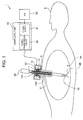
FIG. 1 schematically illustrates the usage state of an operating system including a trocar of a first embodiment. -
FIG. 2 illustrates a circuit configuration of the operating system including the trocar of the first embodiment. -
FIG. 3 is a partial cross sectional view of the trocar of the first embodiment. -
FIG. 4 is a perspective view of a heat dissipation member and a heat insulation member of the trocar of the first embodiment. -
FIG. 5A is a cross sectional view of a heat dissipation member and a power transmission coil of a trocar of the first embodiment. -
FIG. 5B is a cross sectional view of a heat dissipation member and a power transmission coil of a trocar of the first embodiment. -
FIG. 5C is a cross sectional view of a heat dissipation member and a power transmission coil of a trocar of the first embodiment. -
FIG. 6A is a perspective view of a heat dissipation member as a modification example of the first embodiment. -
FIG. 6B is a perspective view of a heat dissipation member as another modification example of the first embodiment. -
FIG. 7 is an exploded view of a heat dissipation member as a modification example of the first embodiment. -
FIG. 8 schematically illustrates the usage state of an operating system including a trocar of a second embodiment. -
FIG. 9 illustrates a circuit configuration of the operating system including the trocar of the second embodiment. -
FIG. 10 illustrates the configuration to describe a flow channel for gas in the operating system including the trocar of the second embodiment. - Referring firstly to
FIGs. 1 to 4 , the following describes anoperating system 1 including atrocar 10 of a first embodiment. As illustrated inFIG. 1 , theoperating system 1 includes thetrocar 10, a power-supply unit 20, atreatment tool 30, and aswitch 23. Although theoperating system 1 allows an endoscope or the like also to be inserted into anabdominal cavity 9A of asubject 9 via another trocar, the descriptions thereof are omitted. - The
trocar 10 of the present embodiment includes ahousing 14, aninsertion tube 14H, apower transmission coil 11, aheat dissipation member 12, and aheat insulation member 13. The long andthin insertion tube 14H that is extended from a lower part of thehousing 14 is inserted into thesubject 9. Thehousing 14 and theinsertion tube 14H are made of the same material and are configured integrally. Thehousing 14 has aninsertion hole 10H at the center, through which thetreatment tool 30 is to be inserted. Theinsertion hole 10H is a through hole that is extended to the forward end of theinsertion tube 14H. - The
treatment tool 30 is inserted into theabdominal cavity 9A through theinsertion hole 10H. Thetreatment tool 30 of the present embodiment is a bipolar electrosurgical knife for treatment, such as incision and coagulation by applying high-frequency electric energy to a part to be treated 9B such as blood vessel that is pinched with atreatment part 32. Thetreatment tool 30 treats there with power that is wirelessly received at a power-reception part 39 (seeFIG. 2 ), and so no cable is connected thereto for power supplying, meaning good operability. - The power-
supply unit 20 to output AC power to thepower transmission coil 11 of thetrocar 10 includes apower supply 21 and apower transmission circuit 22. Thepower supply 21 outputs high-frequency and large power of 10 W to 100 W, for example. As illustrated inFIG. 2 , apower transmission part 19 that generates AC magnetic field from the power supplied from thepower supply 21 includes thepower transmission coil 11, a power-transmission capacitor 15 and a power transmission circuit. Thepower transmission coil 11 is connected in series with the power-transmission capacitor 15, which make up a power-transmission side LC serial resonance circuit that generates AC magnetic field at a predetermined resonance frequency FR1. Thepower supply 21 outputs AC power at the resonance frequency FR1. Instead of the power-transmission capacitor 15, floating capacity of thepower transmission coil 11 may be used in another configuration. Thepower transmission circuit 22 includes an impedance matching circuit (not illustrated) for impedance matching with thepower supply 21 and the resonance circuit. -
FIG. 1 andFIG. 2 illustrate the power-transmission capacitor 15 that is disposed in thetrocar 10 and thepower transmission circuit 22 that is disposed in the power-supply unit 20. Instead, the power-transmission capacitor 15 and thepower transmission circuit 22 may be disposed in thetrocar 10 or in the power-supply unit 20. - The
switch 23 connected to the power-supply unit 20 may be a foot switch for ON/OFF control of the power output from the power-supply unit 20. - As described above, the
treatment tool 30 has the power-reception part 39 including a power-reception coil 31 that is inductively coupled with thepower transmission coil 11 of thepower transmission part 19 and receives power wirelessly via the AC magnetic field. As illustrated inFIG. 2 , the power-reception part 39 includes the power-reception coil 31, a power-reception capacitor 33 and a power-reception circuit 34. The power-reception coil 31 is connected in series with the power-reception capacitor 33, which make up a power-reception side LC serial resonance circuit that effectively receives AC magnetic field at a predetermined resonance frequency FR2. The resonance frequency FR2 of the power-reception side LC serial resonance circuit is substantially the same as the resonance frequency FR1 of the power-transmission side LC serial resonance circuit, and theoperating system 1 performs wireless power |transfer |[M1] effectively based on a magnetic resonance phenomenon. The resonance frequencies FR1 and FR2 may be selected appropriately in the range of 100 kHz to 20 MHz, from which a frequency that is allowed for use by law, e.g., 13.56 MHz is preferably selected. - Instead of the power-
reception capacitor 33, floating capacity of the power-reception coil 31 may be used in another configuration. The power-reception circuit 34 rectifies an AC signal that the power-reception coil 31 receives into a DC signal, followed by smoothing, and then regulates it with a DC/DC converter to have voltage to be supplied to adriving part 35. The power-reception circuit 34 includes an impedance matching circuit (not illustrated) for impedance matching with the drivingpart 35 and the resonance circuit. The drivingpart 35 converts power from the power-reception circuit 34 into power suitable for driving at thetreatment part 32. Thetreatment part 32 such as an electrosurgical knife receives a driving signal at the frequency of 350 kHz and at the voltage of a few hundreds Vpp from the drivingpart 35, for example. - The power-
reception coil 31 that is of a long and thin solenoid type is disposed in the long and thin insertion part of thetreatment tool 30 to be inserted into thesubject 9 along the longer axis direction. The power-reception coil 31 that receives AC magnetic field generated from thepower transmission coil 11 of thetrocar 10 has a center axis that substantially agrees with the center axis of the insertion part. The power-reception coil 31 may have a length of 100 mm or more and 200 mm or less, for example, so as to allow a part thereof to be inserted always into thepower transmission coil 11, which may have a length that is disposed over the total length of the insertion part. The power-reception coil 31 may be surrounded with insulating resin at the periphery, for example. - On the other hand, the
power transmission coil 11 that is disposed inside of thehousing 14 so as to be wound around theinsertion hole 10H of thetrocar 10 receives AC power and when generating AC magnetic field, generates heat due to Joule heat. - The
heat dissipation member 12 that is a cylindrical member having a hollow inside transmits heat generated from thepower transmission coil 11. This can prevent excessive temperature rise at thepower transmission coil 11. Theheat dissipation member 12 serving as a heat sink to which heat generated from thepower transmission coil 11 is transmitted increases in temperature. As illustrated inFIG. 3 and FIG. 4 , for example, theheat insulation member 13 is disposed under theheat dissipation member 12, i.e., on the side closer to the subject than theheat dissipation member 12, the heat insulation member having lower thermal conductivity than theheat dissipation member 12. Theheat insulation member 13 is a cylindrical member that surrounds the lower face of theheat dissipation member 12 and has a hollow inside. That is, theheat dissipation member 12 and theheat insulation member 13 have a throughhole 12H and a throughhole 13H that are substantially the same in diameter, which make up an insertion opening of thetrocar 10. - Even when the
heat dissipation member 12 is heated, theheat insulation member 13 is disposed under theheat dissipation member 12, and so the temperature of thehousing 14 on the lower side does not increase. - The
heat dissipation member 12 preferably has thermal conductivity λ of 15 W/(m·K) or more. That is, theheat dissipation member 12 preferably is made of copper (λ=398 W/ (m·K)), silicon (λ=168 W/ (m·K)), aluminum nitride (λ=150 W/ (m·K)), iron (λ=84 W/ (m·K)), alumina (λ=32 W/ (m·K)), silicon nitride:Si3N4 (λ=27 W/(m·K)) or stainless steel (λ=17 W/ (m·K)), for example. - In order to prevent loss due to eddy current, the
heat dissipation member 12 is preferably non-electrically conductive, and is made of a ceramic material, such as aluminum nitride particularly preferably. - When the
heat dissipation member 12 is made of an electrically-conductive material, thepower transmission coil 11 used has to include a core made of copper or the like that is surrounded with an insulating material. On the other hand, when theheat dissipation member 12 is made of a non-electrically conductive material, the power transmission coil may include a core without being surrounded with an insulating material. - The
heat dissipation member 12 illustrated inFIG. 4 , for example, has coolingfins 12T for better cooling efficiency by increasing the surface area. The coolingfin 12T may have a rod shape, for example, as long as it does not hinder the movement of air between fins. Warmed air moves naturally from down to up in the vicinity of theheat dissipation member 12 so as to generate convection of air in the housing, whereby heat at theheat dissipation member 12 is discharged to the outside. Thehousing 14 of thetrocar 10 may have openings (not illustrated) for ventilation at the upper face and the side face. Air flowing from the opening at the side face into the housing is warmed by theheat dissipation member 12 and is discharged from the opening at the upper face. - Meanwhile, the
heat insulation member 13 preferably has thermal conductivity λ of 0.3 W/(m·K) or less, and is 0.1 W/(m·K) or less particularly preferably. That is, theheat insulation member 13 preferably is made of resin material, such as epoxy resin (λ=0.21 W/(m·K)), silicone resin (λ=0.16 W/(m·K)), urethane resin (λ=0.034 W/(m·K)), silicon sponge (λ=0.08 W/(m·K)) or urethane foam (λ=0.029 W/(m·K)) made of such resin in a foamed shape, or glass wool (λ=0.045 W/(m·K)), for example. A space may be formed, and air (λ=0.024 W/(m·K)) may be used as theheat insulation member 13. - The
heat dissipation member 12 of thetrocar 10 does not increase in temperature excessively because of so-called natural cooling. - The
power transmission coil 11 of thetrocar 10 is not excessively heated due to theheat dissipation member 12 even when large power is applied to thepower transmission coil 11. Since theheat insulation member 13 is disposed under the heat dissipation member 12 (on the subject side), temperature rise of the housing can be suppressed, especially at a part of thehousing 14 that is in contact with thesubject 9. - The following describes
trocars 10A to 10F as modification examples of thetrocar 10 of the first embodiment. All of thetrocars 10A to 10F of the modification examples have the advantageous effects of thetrocar 10 of the first embodiment, and have other additional effects. - The
trocar 10A as modification example 1 inFIG. 5A includes a highthermal conductivity material 12G such as thermal grease or a sheet made of a high thermal conductivity material so as to cover thepower transmission coil 11. The thermal grease may contain silicone resin as a major component, to which metal particles such as silver are mixed for better thermal conductivity. Thetrocar 10A has good heat transmission efficiency. - The
trocar 10B as modification example 2 inFIG. 5B includes apower transmission coil 11 disposed in a spiral-shaped groove at the inner periphery of aheat dissipation member 12B. Thetrocar 10B is configured to facilitate the disposition of thepower transmission coil 11 in a predetermined shape at the inner periphery of theheat dissipation member 12. - The trocar 10C as modification example 3 in
FIG. 5C includes apower transmission coil 11 having a core that is a rectangle in cross section, and the core is inserted into a rectangular groove of a heat dissipation member 12C. The trocar 10C enables more effective transmission of heat generated at thepower transmission coil 11 to theheat dissipation member 12. The core of thepower transmission coil 11 that is a circle in cross section may be inserted into a semicircular groove. That is, theheat dissipation member 12 having a groove that is fitted with the core of thepower transmission coil 11 can widen the contact area between thepower transmission coil 11 and theheat dissipation member 12 and so can improve heat transmission efficiency. - In the configuration of the core of the
power transmission coil 11 inserted in the spiral-shaped groove of the heat dissipation member as well, the highthermal conductivity material 12G, e.g., thermal grease, is preferably disposed at a gap between the groove and the core. - The
trocar 10D as modification example 4 inFIG. 6A includes aheat dissipation member 12D made of an electrically-conductive metal material, in which aslit 12S is formed in the direction orthogonal to the circumferential direction. A metal material is easily processed and is not expensive compared with a ceramic material. The heat dissipation member made of an electrically-conductive member, however, generates eddy current flowing and generates loss when AC magnetic field is applied. Theheat dissipation member 12D having theslit 12S therein, which has conductivity, can reduce such loss from eddy current. Theslit 12S may be air gap or may be made of a non-electrically conductive member. - The
trocar 10E as modification example 5 inFIG. 6B includes a heat dissipation member 12E made up of a plurality of metal members (electrically-conductive members) 12a and 12b that are electrically insulated by a plurality of slits 12S1 and 12S2. - The trocar 10F as modification example 5 in
FIG. 7 includes aheat dissipation member 12F, including an inner tubular member 12F1 around which apower transmission coil 11 is wound, and an outer tubular member 12F2 joined to the outer periphery of the inner tubular member 12F1. Winding of thepower transmission coil 11 around the outer periphery of the inner tubular member 12F1 is easier than winding at the inner periphery. - Further since the
power transmission coil 11 of the trocar 10F is sandwiched between the inner tubular member 12F1 and the outer tubular member 12F2, heat generated at thepower transmission coil 11 can be effectively transmitted to theheat dissipation member 12F. The inner tubular member 12F1 and the outer tubular member 12F2 may be made of the same material or different materials. At least one of the inner tubular member 12F1 and the outer tubular member 12F2 may be made of a high thermal conductivity material, and both of them are made of a high thermal conductivity material particularly preferably. Preferably the inner tubular member 12F1 and the outer tubular member 12F2 are in intimate contact via a high thermal conductivity material, such as thermal grease. - The following describes an
operating system 1G including a trocar 10G that is a second embodiment. Since the trocar 10G is similar to thetrocar 10, the same reference numerals are assigned to common elements, and their descriptions are omitted. - While the
heat dissipation member 12 in thetrocar 10 is naturally cooled, the trocar 10G is forced-cooled. Then temperature rise at the housing of the trocar 10G can be suppressed as compared with thetrocar 10, and the configuration described later has other additional advantageous effects. - That is, as illustrated in
FIG. 8 andFIG. 9 , theoperating system 1G includes a gas-supplyingunit 40 to supply gas for forced-cooling of theheat dissipation member 12, in addition to the elements of theoperating system 1. - A
pneumoperitoneum apparatus 41 of the gas-supplyingunit 40 fills an abdominal cavity to be treated with gas such as carbon dioxide to expand the abdominal cavity, thus keeping the viewing field for observation required to the treatment of the abdominal cavity and so allowing the operator to understand the treatment process sufficiently. Filling of gas into the abdominal cavity by the pneumoperitoneum apparatus is performed under the control of pressure of gas from a gas supplying source (not illustrated) such as a gas cylinder using a pressure-reducing device or a valve so as to keep the pressure in the abdominal cavity at the set pressure. - The trocar 10G includes an
inlet 48 through which gas to cool theheat dissipation member 12 is introduced, aflow channel 47 including a pipe through which the gas flows, and anoutlet 49 through which the gas is discharged. Theinlet 48 is disposed at a lower part of the side face of thehousing 14, and theoutlet 49 is disposed at an upper part of the side face or at the upper face. - The gas-supplying
unit 40 includes a regulatingpart 42 that divides gas supplied from thepneumoperitoneum apparatus 41 into a path to flow in the abdominal cavity and a path to flow in theflow channel 47 to cool theheat dissipation member 12. For instance, as illustrated inFIG. 10 , the regulatingpart 42 includes abranch part 42A, apressure control valve 42B that is controlled based on the pressure inside of the abdominal cavity and apressure control valve 42C to control the flow rate of gas to flow in theflow channel 47. - The
pressure control valves pressure control valve 42B is an active control valve, the pressure on the secondary side (abdominal cavity side) is detected by a pressure sensor (not illustrated) such as a diaphragm sensor, and the valve is controlled so that the measurement of pressure has a predetermined value. Thepressure control valve 42C may have a configuration similar to that of thepressure control valve 42B, and is adjusted so that the pressure on the secondary side has a value required for flowing at the sufficient flow rate for coil cooling. - At least a part of the regulating
part 42, e.g., thepressure control valve 42C may be disposed at thetrocar 10, and thepressure control valve 42B may be disposed at thepneumoperitoneum apparatus 41. - The flow rate of gas supplied to the
flow channel 47 may be set at a predetermined amount, and it is preferable that the regulatingpart 42 makes a flow-rate control part not illustrated regulate the flow rate or the like in accordance with the temperature or the amount of power of thepower transmission coil 11 so as to prevent excessive supply of gas. Although the temperature of thepower transmission coil 11 may be detected by a temperature sensor (not illustrated), it can be estimated from the amount of power applied to thepower transmission coil 11 as well. That is, since the temperature and the amount of power of thepower transmission coil 11 have a proportional relationship, regulation based on the amount of power has the same meaning as the regulation based on the temperature of the power transmission coil. - For instance, control is performed so that gas is supplied to the
flow channel 47 only when the temperature or the amount of power of thepower transmission coil 11 is a predetermined value or more. Alternatively the flow rate of gas to be supplied to theflow channel 47 may be controlled so as to be in proportion to the temperature or the amount of power of thepower transmission coil 11. - The regulating
part 42, which regulates thepressure control valve 42C based on information on the temperature of thepower transmission coil 11 or on the amount of power from the power-supply unit 20, can improve the efficiency of gas supplying and so is economical. - In another configuration, gas subjected to regulation by the
pressure control valve 42B may be supplied to the abdominal cavity via theflow channel 47. The operating system configured to cool thepower transmission coil 11 with gas for pneumoperitoneum is simpler than the configuration of theoperating system 1G. That is, it does not have to include thebranch part 42A and thepressure control valve 42C. - An apparatus exclusively used to supply fluid to cool the heat dissipation member may be provided. In this case, the fluid used may be liquid such as water.
- The present invention is not limited to the above-described embodiments, and can be changed and modified variously without changing the gist of the present invention.
- This application claims the benefit of priority to JP Patent Application No.
2013-172474 filed in Japan on August 22, 2013
Claims (11)
- A trocar, comprising:a housing;an insertion tube that is integral with the housing and is inserted into a subject;a power transmission coil that is disposed inside of the housing and generates AC magnetic field to be applied to an insertion hole into which a treatment tool is to be inserted;a heat dissipation member that transmits heat generated from the power transmission coil; anda heat insulation member disposed on a side of the subject with reference to the heat dissipation member and having lower thermal conductivity than the heat dissipation member.
- The trocar according to claim 1, wherein the heat dissipation member has a circumferential direction and includes an electrically-conductive member having a slit therein in a direction orthogonal to the circumferential direction.
- The trocar according to claim 2, wherein the heat dissipation member includes a plurality of electrically-conductive members that are electrically insulated by a plurality of slits.
- The trocar according to claim 2, wherein the heat dissipation member includes a cylindrical member having an inner periphery on which the power transmission coil is wound.
- The trocar according to claim 4, wherein the heat dissipation member includes:an inner tubular member having an outer periphery around which the power transmission coil is wound; andan outer tubular member joined to the outer periphery of the inner tubular member.
- The trocar according to claim 4 or 5, wherein the heat dissipation member has a spiral-shaped groove, in which the power transmission coil is inserted.
- The trocar according to any one of claims 1 to 6, further comprising:an inlet connecting part through which fluid to cool the heat dissipation member is introduced;a flow channel through which the fluid flows; andan outlet connecting part through which the fluid is discharged.
- The trocar according to claim 7, wherein the fluid is gas supplied from a pneumoperitoneum apparatus.
- The trocar according to claim 8, wherein the gas is supplied into an abdominal cavity of a subject via the flow channel.
- The trocar according to claim 8, wherein the gas to be supplied to the flow channel is regulated in accordance with temperature or an amount of power at the power transmission coil.
- The trocar according to claim 10, wherein when the temperature or the amount of power at the power transmission coil is a predetermined value or more, the gas is supplied to the flow channel.
Applications Claiming Priority (2)
| Application Number | Priority Date | Filing Date | Title |
|---|---|---|---|
| JP2013172474A JP6049569B2 (en) | 2013-08-22 | 2013-08-22 | Surgical system and trocar |
| PCT/JP2014/056339 WO2015025547A1 (en) | 2013-08-22 | 2014-03-11 | Trocar |
Publications (2)
| Publication Number | Publication Date |
|---|---|
| EP3037052A1 true EP3037052A1 (en) | 2016-06-29 |
| EP3037052A4 EP3037052A4 (en) | 2017-04-19 |
Family
ID=52483338
Family Applications (1)
| Application Number | Title | Priority Date | Filing Date |
|---|---|---|---|
| EP14838264.1A Withdrawn EP3037052A4 (en) | 2013-08-22 | 2014-03-11 | Trocar |
Country Status (5)
| Country | Link |
|---|---|
| US (1) | US20150359565A1 (en) |
| EP (1) | EP3037052A4 (en) |
| JP (1) | JP6049569B2 (en) |
| CN (1) | CN105473082A (en) |
| WO (1) | WO2015025547A1 (en) |
Families Citing this family (7)
| Publication number | Priority date | Publication date | Assignee | Title |
|---|---|---|---|---|
| JP6362762B2 (en) * | 2015-02-27 | 2018-07-25 | オリンパス株式会社 | Medical power supply system |
| CN108848667B (en) * | 2015-12-11 | 2019-06-14 | 天津瑞奇外科器械股份有限公司 | Modular signal interface system and energy piercer |
| EP4049603B1 (en) | 2017-06-15 | 2024-01-31 | Reach Surgical, Inc. | Electrosurgical systems |
| US12157239B2 (en) | 2019-01-07 | 2024-12-03 | Spyderco, Inc. | Knife with integral sealed power source |
| US12318953B2 (en) | 2019-01-07 | 2025-06-03 | Spyderco, Inc. | Knife with integral sealed power source |
| US20210186591A1 (en) * | 2019-12-23 | 2021-06-24 | Gyrus Acmi, Inc. D/B/A Olympus Surgical Technologies America | Inductive power joint allowing unrestricted rotation |
| CN111991670A (en) * | 2020-09-02 | 2020-11-27 | 杭州富阳万博空分设备有限公司 | Constant-temperature household oxygen generator and use method thereof |
Family Cites Families (10)
| Publication number | Priority date | Publication date | Assignee | Title |
|---|---|---|---|---|
| US5792141A (en) * | 1996-03-05 | 1998-08-11 | Medicor Corporation | Electrosurgical device for preventing capacitive coupling and the formation of undesirable current paths |
| US5961514A (en) * | 1997-05-14 | 1999-10-05 | Ethicon Endo-Surger, Inc. | Cordless electrosurgical instrument |
| US5849020A (en) * | 1997-06-30 | 1998-12-15 | Ethicon Endo-Surgery, Inc. | Inductively coupled electrosurgical instrument |
| US5916215A (en) * | 1997-06-30 | 1999-06-29 | Ethicon Endo-Surgery, Inc. | Inductively coupled electrosurgical trocar |
| US5791308A (en) * | 1997-07-18 | 1998-08-11 | Precision Combustion, Inc. | Plug assembly |
| US20060276781A1 (en) * | 2004-04-29 | 2006-12-07 | Van Der Weide Daniel W | Cannula cooling and positioning device |
| US7540852B2 (en) * | 2004-08-26 | 2009-06-02 | Flowcardia, Inc. | Ultrasound catheter devices and methods |
| US8915845B2 (en) * | 2008-05-14 | 2014-12-23 | Physcient, Inc. | Methods and devices to decrease tissue trauma during surgery |
| US9017279B2 (en) * | 2009-10-05 | 2015-04-28 | Stryker Corporation | Method and apparatus for providing heat to insufflation gases |
| US9005198B2 (en) * | 2010-01-29 | 2015-04-14 | Ethicon Endo-Surgery, Inc. | Surgical instrument comprising an electrode |
-
2013
- 2013-08-22 JP JP2013172474A patent/JP6049569B2/en not_active Expired - Fee Related
-
2014
- 2014-03-11 CN CN201480045512.8A patent/CN105473082A/en active Pending
- 2014-03-11 WO PCT/JP2014/056339 patent/WO2015025547A1/en not_active Ceased
- 2014-03-11 EP EP14838264.1A patent/EP3037052A4/en not_active Withdrawn
-
2015
- 2015-08-26 US US14/835,860 patent/US20150359565A1/en not_active Abandoned
Also Published As
| Publication number | Publication date |
|---|---|
| WO2015025547A1 (en) | 2015-02-26 |
| JP6049569B2 (en) | 2016-12-21 |
| JP2015039549A (en) | 2015-03-02 |
| CN105473082A (en) | 2016-04-06 |
| EP3037052A4 (en) | 2017-04-19 |
| US20150359565A1 (en) | 2015-12-17 |
Similar Documents
| Publication | Publication Date | Title |
|---|---|---|
| EP3037052A1 (en) | Trocar | |
| US20170035402A1 (en) | Medical instrument, insertion assisting tool and medical system | |
| AU2021202777B2 (en) | Induction coil assembly for uterine ablation and method | |
| US9833124B2 (en) | Treatment tool and endoscope system with inductance elements to power treatment device of treatment tool | |
| JP2012523923A5 (en) | ||
| KR20220092512A (en) | introducer for electrosurgical instruments | |
| JP2016002201A (en) | Medical instruments | |
| KR20160107492A (en) | An Apparatus for Cooling an Ultrasound Cutter and a Method for Cooling an Ultrasound Cutter Using the Same | |
| EP3045131A1 (en) | Treatment tool and surgical system | |
| EP3056159B1 (en) | Medical device | |
| WO2016071983A1 (en) | Trocar and medical wireless power feeding system | |
| JP2015208549A (en) | Trocar | |
| JP2015226661A (en) | Medical equipment | |
| HK40102811A (en) | Induction coil assembly for uterine ablation and method | |
| HK40075114A (en) | Introducer for electrosurgical instrument | |
| JP2015104628A (en) | Trocar and operation system | |
| JP6883794B2 (en) | Warmer using microwave irradiation | |
| TWI584777B (en) | Flexible deep magnetic field generating apparatus | |
| JP2015104629A (en) | Medical appliance and medical system |
Legal Events
| Date | Code | Title | Description |
|---|---|---|---|
| PUAI | Public reference made under article 153(3) epc to a published international application that has entered the european phase |
Free format text: ORIGINAL CODE: 0009012 |
|
| 17P | Request for examination filed |
Effective date: 20160311 |
|
| AK | Designated contracting states |
Kind code of ref document: A1 Designated state(s): AL AT BE BG CH CY CZ DE DK EE ES FI FR GB GR HR HU IE IS IT LI LT LU LV MC MK MT NL NO PL PT RO RS SE SI SK SM TR |
|
| AX | Request for extension of the european patent |
Extension state: BA ME |
|
| RAP1 | Party data changed (applicant data changed or rights of an application transferred) |
Owner name: OLYMPUS CORPORATION |
|
| RIN1 | Information on inventor provided before grant (corrected) |
Inventor name: MATSUI, AKIRA |
|
| DAX | Request for extension of the european patent (deleted) | ||
| A4 | Supplementary search report drawn up and despatched |
Effective date: 20170321 |
|
| RIC1 | Information provided on ipc code assigned before grant |
Ipc: A61B 17/34 20060101AFI20170315BHEP Ipc: A61B 18/14 20060101ALI20170315BHEP |
|
| STAA | Information on the status of an ep patent application or granted ep patent |
Free format text: STATUS: REQUEST FOR EXAMINATION WAS MADE |
|
| STAA | Information on the status of an ep patent application or granted ep patent |
Free format text: STATUS: THE APPLICATION IS DEEMED TO BE WITHDRAWN |
|
| 18D | Application deemed to be withdrawn |
Effective date: 20171018 |