EP3036474B1 - A luminary with a wireless transmitter - Google Patents
A luminary with a wireless transmitter Download PDFInfo
- Publication number
- EP3036474B1 EP3036474B1 EP14752350.0A EP14752350A EP3036474B1 EP 3036474 B1 EP3036474 B1 EP 3036474B1 EP 14752350 A EP14752350 A EP 14752350A EP 3036474 B1 EP3036474 B1 EP 3036474B1
- Authority
- EP
- European Patent Office
- Prior art keywords
- luminary
- casing
- energy
- ceiling plate
- antenna
- Prior art date
- Legal status (The legal status is an assumption and is not a legal conclusion. Google has not performed a legal analysis and makes no representation as to the accuracy of the status listed.)
- Not-in-force
Links
Images
Classifications
-
- F—MECHANICAL ENGINEERING; LIGHTING; HEATING; WEAPONS; BLASTING
- F21—LIGHTING
- F21S—NON-PORTABLE LIGHTING DEVICES; SYSTEMS THEREOF; VEHICLE LIGHTING DEVICES SPECIALLY ADAPTED FOR VEHICLE EXTERIORS
- F21S8/00—Lighting devices intended for fixed installation
- F21S8/03—Lighting devices intended for fixed installation of surface-mounted type
-
- F—MECHANICAL ENGINEERING; LIGHTING; HEATING; WEAPONS; BLASTING
- F21—LIGHTING
- F21S—NON-PORTABLE LIGHTING DEVICES; SYSTEMS THEREOF; VEHICLE LIGHTING DEVICES SPECIALLY ADAPTED FOR VEHICLE EXTERIORS
- F21S8/00—Lighting devices intended for fixed installation
- F21S8/04—Lighting devices intended for fixed installation intended only for mounting on a ceiling or the like overhead structures
-
- F—MECHANICAL ENGINEERING; LIGHTING; HEATING; WEAPONS; BLASTING
- F21—LIGHTING
- F21V—FUNCTIONAL FEATURES OR DETAILS OF LIGHTING DEVICES OR SYSTEMS THEREOF; STRUCTURAL COMBINATIONS OF LIGHTING DEVICES WITH OTHER ARTICLES, NOT OTHERWISE PROVIDED FOR
- F21V21/00—Supporting, suspending, or attaching arrangements for lighting devices; Hand grips
- F21V21/02—Wall, ceiling, or floor bases; Fixing pendants or arms to the bases
- F21V21/03—Ceiling bases, e.g. ceiling roses
-
- F—MECHANICAL ENGINEERING; LIGHTING; HEATING; WEAPONS; BLASTING
- F21—LIGHTING
- F21V—FUNCTIONAL FEATURES OR DETAILS OF LIGHTING DEVICES OR SYSTEMS THEREOF; STRUCTURAL COMBINATIONS OF LIGHTING DEVICES WITH OTHER ARTICLES, NOT OTHERWISE PROVIDED FOR
- F21V23/00—Arrangement of electric circuit elements in or on lighting devices
- F21V23/04—Arrangement of electric circuit elements in or on lighting devices the elements being switches
- F21V23/0435—Arrangement of electric circuit elements in or on lighting devices the elements being switches activated by remote control means
-
- F—MECHANICAL ENGINEERING; LIGHTING; HEATING; WEAPONS; BLASTING
- F21—LIGHTING
- F21V—FUNCTIONAL FEATURES OR DETAILS OF LIGHTING DEVICES OR SYSTEMS THEREOF; STRUCTURAL COMBINATIONS OF LIGHTING DEVICES WITH OTHER ARTICLES, NOT OTHERWISE PROVIDED FOR
- F21V23/00—Arrangement of electric circuit elements in or on lighting devices
- F21V23/04—Arrangement of electric circuit elements in or on lighting devices the elements being switches
- F21V23/0442—Arrangement of electric circuit elements in or on lighting devices the elements being switches activated by means of a sensor, e.g. motion or photodetectors
- F21V23/045—Arrangement of electric circuit elements in or on lighting devices the elements being switches activated by means of a sensor, e.g. motion or photodetectors the sensor receiving a signal from a remote controller
-
- F—MECHANICAL ENGINEERING; LIGHTING; HEATING; WEAPONS; BLASTING
- F21—LIGHTING
- F21V—FUNCTIONAL FEATURES OR DETAILS OF LIGHTING DEVICES OR SYSTEMS THEREOF; STRUCTURAL COMBINATIONS OF LIGHTING DEVICES WITH OTHER ARTICLES, NOT OTHERWISE PROVIDED FOR
- F21V7/00—Reflectors for light sources
-
- H—ELECTRICITY
- H01—ELECTRIC ELEMENTS
- H01Q—ANTENNAS, i.e. RADIO AERIALS
- H01Q1/00—Details of, or arrangements associated with, antennas
- H01Q1/12—Supports; Mounting means
- H01Q1/22—Supports; Mounting means by structural association with other equipment or articles
-
- H—ELECTRICITY
- H01—ELECTRIC ELEMENTS
- H01Q—ANTENNAS, i.e. RADIO AERIALS
- H01Q7/00—Loop antennas with a substantially uniform current distribution around the loop and having a directional radiation pattern in a plane perpendicular to the plane of the loop
-
- H—ELECTRICITY
- H05—ELECTRIC TECHNIQUES NOT OTHERWISE PROVIDED FOR
- H05B—ELECTRIC HEATING; ELECTRIC LIGHT SOURCES NOT OTHERWISE PROVIDED FOR; CIRCUIT ARRANGEMENTS FOR ELECTRIC LIGHT SOURCES, IN GENERAL
- H05B47/00—Circuit arrangements for operating light sources in general, i.e. where the type of light source is not relevant
- H05B47/10—Controlling the light source
- H05B47/175—Controlling the light source by remote control
- H05B47/19—Controlling the light source by remote control via wireless transmission
Definitions
- the present invention relates to a luminary which incorporates a wireless transmitter.
- Luminaries constitute a basic component of many lighting solutions, particularly intelligent lighting solutions incorporating light emitting diode (LED) lighting.
- Another important component of intelligent lighting systems is control modules which are equipped with a radio and antenna to provide wireless connectivity.
- the control modules operate in a communication mesh, where each module constitutes a node of the mesh.
- control modules are often integrated in luminaries.
- Luminaries are typically manufactured with metal and plastic materials. In particular, any metal parts can have a high impact on the radiation properties of the antenna.
- the quality of the communication propagation distance and package error rate (PER)) within the mesh depends very much on the radiation properties of the antenna as integrated into the illumination system.
- PER package error rate
- WO2010/116269 discloses a ceiling luminaire with a slot antenna.
- An alternative solution to the provision of gaps and holes is to provide external (e.g. patch) antennas on an outer surface of the luminary. Such external antennas are expensive.
- a luminary configured for attachment to a ceiling of a space to be illuminated, the luminary comprising: a casing; a fixture for securing a lighting component to the casing: a wireless transmitter module comprising an antenna located in the casing; and a securing component arranged to secure the luminary with respect to a ceiling plate and configured to space the casing from the ceiling plate to provide an air-gap between the casing and the ceiling plate, whereby the casing constitutes a resonant cavity for RF energy transmitted from the antenna, the air-gap dimensioned to radiate RF energy from the antenna to the environment externally of the casing.
- an illumination system configured for attachment to a ceiling of a space to be illuminated, the illumination system comprising: at least one luminary as hereinabove defined, and a ceiling plate secured to the luminary by the securing component.
- the illumination system can comprise multiple luminaries spaced apart in an array, each luminary being as hereinabove defined and intended to communicate with each other through the radiation of RF energy from their respective antennas.
- an air-gap is used between a metal luminary and a metal ceiling plate on which the luminary is installed.
- the inventors have noticed that the use of an air-gap between the metal luminary and the ceiling plate results in better radiation properties than by using holes in the luminary itself.
- efficient radiation properties can be achieved without the need for such holes in the luminaries, and also without having to resort to external antennas which can be expensive. It is advantageous to avoid the use of holes in the external walls of the luminaries, because holes require additional production steps to manufacture, and additional measures for safety requirements in use.
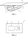
- FIG 1 is a schematic block diagram of an embodiment.
- Figure 1 shows a single luminary made of any appropriate material, but typically of metal.
- the luminary of this embodiment is a so-called metal gear-tray luminary.
- the luminary 1 comprises a channel 2 of rectangular cross-section having a solid base 4 and solid side walls 6.
- a control module 8 is positioned inside the luminary on the base 4.
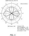
- the control module 8 comprises an antenna 10 placed on an RF board 12 ( Figure 2 ).
- the antenna 10 is connected to an RF generator component 14 which generates RF energy to provide control signals which are to be transmitted from the module 8.
- the RF generator 14 incorporates a controller or responds to a controller to determine the control signals to be generated, in a manner which is known per se and not described further herein.
- the control signals are intended to be received by other control modules in an illumination system as described more fully herein.
- the luminary 1 has a reflector 16 secured to the underside of the base, with sloping walls having a reflective material on their inner side.
- the luminary 1 is equipped with at least one lighting component secured to the underside of the base 4 using one or more suitable fixture, such that the lighting component emits light to be reflected downwardly by the reflector.
- the lighting components can be arranged to be under the control of the control signals which are exchanged between luminaries of the system, via a control module at each luminary.
- the rectangular channel is provided at each upper edge by longitudinally extending portions which support inwardly angled walls 18.
- the side wall 6, the longitudinally extending portions and the inwardly angled walls 18 are all solid, that is they are formed of a continuous material, without gaps or holes. It is understood in this context that there may be matters of construction which have led for example, to screw holes or other fixtures and fittings to be inserted into the luminary, but there are no specially designed gaps and holes for the purposes of radiation emission.
- the luminary is provided with a securing component (not shown) which secures the luminary 1 with respect to a ceiling plate 20, for example, of metal.
- the ceiling plate 20 is a substantially planar continuous sheet of material, for example, metal, secured to the ceiling or forming part of the ceiling.
- the luminary can be secured to the ceiling plate 20 itself, or to another part of the ceiling such that it is secured with respect to the ceiling plate. Either way, an air-gap 22 is formed between the upper edge of the inwardly directed walls 18 of the luminary channel and the lower surface of the ceiling plate 20.
- the inventors have noted that the use of an air-gap between the metal luminary and ceiling plate results in better radiation properties than by using holes in the luminary itself. Besides the positive effect that this air-gap enables the electromagnetic energy radiated from the antenna 10 to radiate efficiently to the environment, use of the air-gap also provides a radiation pattern with useful directivity properties.
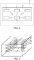
- Figure 3 shows the radiation pattern from a top down view of a radiation structure in the luminary of Figure 1 .
- the pattern of Figure 3 assumes that the antenna 10 is located in the base to emit RF radiation in a direction substantially along the length of the rectangular channel, for example, away from the viewer in Figure 1 . Viewed from the side, the radiation pattern has downward lobes. This is also beneficial since it enables devices below ceiling level to receive RF signals from the luminary. See figures 6A and 6B which show the radiation pattern in 3D and 2D respectively (from the side).
- Figure 3 shows the radiation pattern from above. It is a substantially cruciform pattern which is ideal for luminaries which are positioned in a rectangular array. This is particularly relevant for lighting solutions where the luminaries are configured in array grids, for example, in offices or parking garages.
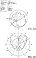
- An example is shown in Figure 4 , which shows the underside of an illumination system in which an array of luminaries 1 are shown secured to the underside of a ceiling plate 20, which is itself shown with respect to the ceiling 24.
- the luminary marked TX is shown radiating, with the intention that signals radiated from the luminary 1 marked TX will be picked up by the other luminaries in the array.
- the cruciform radiation pattern of Figure 3 is particularly appropriate to achieve this, and also represents an efficient solution.
- each luminary can comprise a control module as described above in relation to Figure 1 .
- the control modules operate in a communication mesh, where each module constitutes a node of the mesh. This allows the luminaries to communicate with one another and to control the lighting levels.
- the quality of the communication (propagation distance and package error rate) within the mesh is much improved by the efficient radiation pattern obtained by use of the air-gap.
- the material of the ceiling 24 can be either metal or concrete, and by use of a metal ceiling plate both situations can be coped with.
- the air-gap principle works particularly well for luminaries shaped as shown in Figure 1 with a rectangular channel gear-tray. However, it is also applicable for other types of luminaries, as will be evident from the following description.
- the mechanism of the air-gap concept is based on a resonant cavity.
- the metal channel 2 of the luminary 1 forms, with the ceiling plate 20, a resonant cavity.
- the control module 8 including the antenna 10 is a source of RF energy inside the cavity and the energy is distributed according to a transversal magnetic (TM) field pattern over the casing as shown in Figure 5 .
- the dotted lines indicate the magnetic field lines, which correspond to the surface currents. Subsequently, when an air-gap is applied as proposed above, then these surface currents are blocked and according to Faraday's law an induced voltage (and a corresponding electric field) will occur within the aperture created by the air-gap.
- the bold lines indicate electric field lines.
- the air-gap operates as a type of slot/aperture antenna to augment the wire antenna 10 which has generated the RF energy from the control module 8.
- the aperture 22 is excited from the inside energy and radiates the energy to the outside of the casing formed by the wall 6 and base 4.
- the air-gap can be suitable dimensioned for any size of luminary structure taking into account the wavelength of radiation and the casing characteristics. In one example, it has been shown that a minimum of 3mm provides particularly effective radiation in combination with an optimal radiation pattern when used with the gear-tray luminary shown in Figure 1 and the array of Figure 4 .
- the radiation pattern can be slightly influenced by the longitudinal positioning of the transmitter module in the luminary, but this does not have a negative impact on the radiation efficiency nor on the gear-tray communication mesh performance. Moreover, the length of the luminary can have an effect on the radiation pattern, but nevertheless the overall advantages remain.
- the unique benefit of the concept of using an air-gap between a metal luminary and a metal ceiling plate is that it combines an efficient pathway for the electromagnetic energy to the environment (including the nodes of the connectivity mesh) as well as directivity properties which are optimal for luminaries placed in an arrayed grid such as in offices and parking garages.
- the air-gap principle is very effective for achieving excellent radiation properties.
- it prevents additional measures in the luminary, such as holes, as well as the use of external antennas, resulting in a cost-effective solution.
Description
- The present invention relates to a luminary which incorporates a wireless transmitter.
- Luminaries (or luminaires) constitute a basic component of many lighting solutions, particularly intelligent lighting solutions incorporating light emitting diode (LED) lighting. Another important component of intelligent lighting systems is control modules which are equipped with a radio and antenna to provide wireless connectivity. The control modules operate in a communication mesh, where each module constitutes a node of the mesh. Presently, control modules are often integrated in luminaries. Luminaries are typically manufactured with metal and plastic materials. In particular, any metal parts can have a high impact on the radiation properties of the antenna. The quality of the communication (propagation distance and package error rate (PER)) within the mesh depends very much on the radiation properties of the antenna as integrated into the illumination system.
- Currently, specifically designed gaps and holes are provided in the luminaries in order to enable electromagnetic energy to propagate properly to the environment.
WO2010/116269 discloses a ceiling luminaire with a slot antenna. An alternative solution to the provision of gaps and holes is to provide external (e.g. patch) antennas on an outer surface of the luminary. Such external antennas are expensive. - According to one aspect of the invention there is provided a luminary configured for attachment to a ceiling of a space to be illuminated, the luminary comprising: a casing; a fixture for securing a lighting component to the casing: a wireless transmitter module comprising an antenna located in the casing; and
a securing component arranged to secure the luminary with respect to a ceiling plate and configured to space the casing from the ceiling plate to provide an air-gap between the casing and the ceiling plate, whereby the casing constitutes a resonant cavity for RF energy transmitted from the antenna, the air-gap dimensioned to radiate RF energy from the antenna to the environment externally of the casing. - Another aspect of the invention provides an illumination system configured for attachment to a ceiling of a space to be illuminated, the illumination system comprising:
at least one luminary as hereinabove defined, and a ceiling plate secured to the luminary by the securing component. - The illumination system can comprise multiple luminaries spaced apart in an array, each luminary being as hereinabove defined and intended to communicate with each other through the radiation of RF energy from their respective antennas.
- For a better understanding of the present invention and to show how the same may be carried into effect, reference will now be made by way of example to the accompanying drawings.
-
-
Fig. 1 is a schematic perspective view of an illumination system; -
Fig. 2 is a schematic view of a transmitter module; -
Fig. 3 is a schematic plan view of a radiation pattern; -
Fig. 4 is a schematic block diagram of an illumination system seen from below; -
Fig. 5 is a schematic perspective view of a luminary casing operating as a resonant cavity; -
Fig. 6A is a schematic view of the radiation pattern in 3D; -
Fig. 6B is a schematic view of the radiation pattern from the side. - In the present disclosure, an air-gap is used between a metal luminary and a metal ceiling plate on which the luminary is installed. The inventors have noticed that the use of an air-gap between the metal luminary and the ceiling plate results in better radiation properties than by using holes in the luminary itself. Moreover, efficient radiation properties can be achieved without the need for such holes in the luminaries, and also without having to resort to external antennas which can be expensive. It is advantageous to avoid the use of holes in the external walls of the luminaries, because holes require additional production steps to manufacture, and additional measures for safety requirements in use.
-
Figure 1 is a schematic block diagram of an embodiment.Figure 1 shows a single luminary made of any appropriate material, but typically of metal. The luminary of this embodiment is a so-called metal gear-tray luminary. Theluminary 1 comprises achannel 2 of rectangular cross-section having asolid base 4 andsolid side walls 6. Acontrol module 8 is positioned inside the luminary on thebase 4. Thecontrol module 8 comprises anantenna 10 placed on an RF board 12 (Figure 2 ). Theantenna 10 is connected to anRF generator component 14 which generates RF energy to provide control signals which are to be transmitted from themodule 8. TheRF generator 14 incorporates a controller or responds to a controller to determine the control signals to be generated, in a manner which is known per se and not described further herein. The control signals are intended to be received by other control modules in an illumination system as described more fully herein. - The
luminary 1 has areflector 16 secured to the underside of the base, with sloping walls having a reflective material on their inner side. - The
luminary 1 is equipped with at least one lighting component secured to the underside of thebase 4 using one or more suitable fixture, such that the lighting component emits light to be reflected downwardly by the reflector. The lighting components can be arranged to be under the control of the control signals which are exchanged between luminaries of the system, via a control module at each luminary. - The rectangular channel is provided at each upper edge by longitudinally extending portions which support inwardly angled walls 18. The
side wall 6, the longitudinally extending portions and the inwardly angled walls 18 are all solid, that is they are formed of a continuous material, without gaps or holes. It is understood in this context that there may be matters of construction which have led for example, to screw holes or other fixtures and fittings to be inserted into the luminary, but there are no specially designed gaps and holes for the purposes of radiation emission. - The luminary is provided with a securing component (not shown) which secures the
luminary 1 with respect to aceiling plate 20, for example, of metal. Theceiling plate 20 is a substantially planar continuous sheet of material, for example, metal, secured to the ceiling or forming part of the ceiling. The luminary can be secured to theceiling plate 20 itself, or to another part of the ceiling such that it is secured with respect to the ceiling plate. Either way, an air-gap 22 is formed between the upper edge of the inwardly directed walls 18 of the luminary channel and the lower surface of theceiling plate 20. - As mentioned, the inventors have noted that the use of an air-gap between the metal luminary and ceiling plate results in better radiation properties than by using holes in the luminary itself. Besides the positive effect that this air-gap enables the electromagnetic energy radiated from the
antenna 10 to radiate efficiently to the environment, use of the air-gap also provides a radiation pattern with useful directivity properties. -
Figure 3 shows the radiation pattern from a top down view of a radiation structure in the luminary ofFigure 1 . The pattern ofFigure 3 assumes that theantenna 10 is located in the base to emit RF radiation in a direction substantially along the length of the rectangular channel, for example, away from the viewer inFigure 1 . Viewed from the side, the radiation pattern has downward lobes. This is also beneficial since it enables devices below ceiling level to receive RF signals from the luminary. Seefigures 6A and 6B which show the radiation pattern in 3D and 2D respectively (from the side). -
Figure 3 shows the radiation pattern from above. It is a substantially cruciform pattern which is ideal for luminaries which are positioned in a rectangular array. This is particularly relevant for lighting solutions where the luminaries are configured in array grids, for example, in offices or parking garages. An example is shown inFigure 4 , which shows the underside of an illumination system in which an array ofluminaries 1 are shown secured to the underside of aceiling plate 20, which is itself shown with respect to theceiling 24. The luminary marked TX is shown radiating, with the intention that signals radiated from theluminary 1 marked TX will be picked up by the other luminaries in the array. Thus, the cruciform radiation pattern ofFigure 3 is particularly appropriate to achieve this, and also represents an efficient solution. - In
Figure 4 , each luminary can comprise a control module as described above in relation toFigure 1 . The control modules operate in a communication mesh, where each module constitutes a node of the mesh. This allows the luminaries to communicate with one another and to control the lighting levels. The quality of the communication (propagation distance and package error rate) within the mesh is much improved by the efficient radiation pattern obtained by use of the air-gap. - The material of the
ceiling 24 can be either metal or concrete, and by use of a metal ceiling plate both situations can be coped with. The air-gap principle works particularly well for luminaries shaped as shown inFigure 1 with a rectangular channel gear-tray. However, it is also applicable for other types of luminaries, as will be evident from the following description. - The mechanism of the air-gap concept is based on a resonant cavity. The
metal channel 2 of theluminary 1 forms, with theceiling plate 20, a resonant cavity. Thecontrol module 8 including theantenna 10 is a source of RF energy inside the cavity and the energy is distributed according to a transversal magnetic (TM) field pattern over the casing as shown inFigure 5 . The dotted lines indicate the magnetic field lines, which correspond to the surface currents. Subsequently, when an air-gap is applied as proposed above, then these surface currents are blocked and according to Faraday's law an induced voltage (and a corresponding electric field) will occur within the aperture created by the air-gap. The bold lines indicate electric field lines. The air-gap operates as a type of slot/aperture antenna to augment thewire antenna 10 which has generated the RF energy from thecontrol module 8. Theaperture 22 is excited from the inside energy and radiates the energy to the outside of the casing formed by thewall 6 andbase 4. The air-gap can be suitable dimensioned for any size of luminary structure taking into account the wavelength of radiation and the casing characteristics. In one example, it has been shown that a minimum of 3mm provides particularly effective radiation in combination with an optimal radiation pattern when used with the gear-tray luminary shown inFigure 1 and the array ofFigure 4 . - However, as the concept is based on a resonant cavity, the exact shape of the luminary and the location of the
control module 8 within the luminary are not critical for the efficiency of radiation as long as the typical field distribution (TM) remains dominant. This should be the case as long as the luminary cross-section does not exceed a few (≈1 to 4) wavelengths of the emitted radiation. For example, with the 2.4 GHz ISM band (wavelength = 12.5cm), the cross-section should be smaller than 15 to 50cm. - The radiation pattern can be slightly influenced by the longitudinal positioning of the transmitter module in the luminary, but this does not have a negative impact on the radiation efficiency nor on the gear-tray communication mesh performance. Moreover, the length of the luminary can have an effect on the radiation pattern, but nevertheless the overall advantages remain.
- The unique benefit of the concept of using an air-gap between a metal luminary and a metal ceiling plate is that it combines an efficient pathway for the electromagnetic energy to the environment (including the nodes of the connectivity mesh) as well as directivity properties which are optimal for luminaries placed in an arrayed grid such as in offices and parking garages. Especially for metal gear-tray-types of luminaries, the air-gap principle is very effective for achieving excellent radiation properties. Moreover, it prevents additional measures in the luminary, such as holes, as well as the use of external antennas, resulting in a cost-effective solution.
- Other variations to the disclosed embodiments can be understood and effected by those skilled in the art in practice of the claimed invention, from a study of the drawings, the disclosure, and the appended claims. In the claims, the word "comprising" does not exclude other elements or steps, and the indefinite article "a" or "an" does not exclude a plurality. A single processor or other unit may fulfill the functions of several items recited in the claims. The mere fact that certain measures are cited in mutually different dependent claims does not indicate that a combination of these measures cannot be used to advantage. Any reference signs in the claims should not be construed as limiting the scope.
Claims (15)
- A metal luminary (1) configured for attachment to a ceiling (24) of a space to be illuminated, the luminary comprising:a casing (2, 4, 6, 18);a fixture for securing a lighting component to the casing:a wireless transmitter module (8) arranged to transmit RF energy to another device, the wireless transmitter module comprising an antenna (10) located in the casing, whereby the casing constitutes a resonant cavity for RF energy transmitted from the antenna; anda securing component arranged to secure the luminary with respect to a metal ceiling plate (20) and configured to space the casing from the ceiling plate to provide an air-gap (22) between the casing and the ceiling plate, whereby the casing constitutes a resonant cavity for RF energy transmitted from the antenna, the air-gap dimensioned to radiate RF energy from the antenna to the environment externally of the casing.
- A luminary according to claim 1, wherein the resonant cavity operates to distribute the RF energy according to a transversal magnetic mode field pattern within the casing.
- A luminary according to claim 1, wherein the radiation pattern of the radiated RF energy is substantially cruciform in a plane substantially parallel to the ceiling plate.
- A luminary according to claim 1, wherein the wireless transmitter module comprises an RF generator (14) for generating control signals to be transmitted in the RF energy transmitted from the antenna.
- A luminary according to claim 1, which comprises at least one lighting component secured to the fixture.
- A luminary according to claim 1, wherein the casing comprises a solid base (4) with upwardly extending solid walls (6).
- A luminary according to claim 3, comprising a reflector (16) extending downwardly from the base and outwardly of the casing.
- A luminary according to claim 1, wherein the casing comprises a rectangular channel having a lower surface providing a base portion (4) with upwardly extending wall portions (6), wherein the wireless transmitter module is secured to the lower surface, the antenna radiating RF energy in a direction along the channel.
- A luminary according to claim 1, wherein the air-gap (22) is at least 3mm in depth.
- A luminary according to claim 8, wherein the width of the rectangular channel is of the order of a few wavelengths of the radiation.
- A luminary according to claim 3 wherein the radiation pattern has downward lobes when viewed from the side.
- A luminary according to claim 8 wherein the upwardly extending wall portions (6) are formed of a continuous material without gaps or holes.
- An illumination system for securement to a ceiling of a space to be illuminated, the illumination system comprising:
a metal ceiling plate (20); at least one luminary secured to the ceiling plate, the luminary being according to any one of the claims 1 to 13. - A system according to claim 13, comprising multiple luminaries organized in an array and secured to the ceiling plate.
- A system according to claim 14, wherein each luminary comprises a node in a mesh network constituted by the array, the luminaries arranged to communicate using control signals in the radiated RF energy.
Priority Applications (1)
| Application Number | Priority Date | Filing Date | Title |
|---|---|---|---|
| EP14752350.0A EP3036474B1 (en) | 2013-08-23 | 2014-08-18 | A luminary with a wireless transmitter |
Applications Claiming Priority (3)
| Application Number | Priority Date | Filing Date | Title |
|---|---|---|---|
| EP13181607 | 2013-08-23 | ||
| EP14752350.0A EP3036474B1 (en) | 2013-08-23 | 2014-08-18 | A luminary with a wireless transmitter |
| PCT/EP2014/067601 WO2015024917A1 (en) | 2013-08-23 | 2014-08-18 | A luminary with a wireless transmitter |
Publications (2)
| Publication Number | Publication Date |
|---|---|
| EP3036474A1 EP3036474A1 (en) | 2016-06-29 |
| EP3036474B1 true EP3036474B1 (en) | 2018-06-13 |
Family
ID=49033913
Family Applications (1)
| Application Number | Title | Priority Date | Filing Date |
|---|---|---|---|
| EP14752350.0A Not-in-force EP3036474B1 (en) | 2013-08-23 | 2014-08-18 | A luminary with a wireless transmitter |
Country Status (6)
| Country | Link |
|---|---|
| US (1) | US20160223153A1 (en) |
| EP (1) | EP3036474B1 (en) |
| JP (1) | JP6493990B2 (en) |
| CN (1) | CN105705857B (en) |
| RU (1) | RU2673559C2 (en) |
| WO (1) | WO2015024917A1 (en) |
Families Citing this family (8)
| Publication number | Priority date | Publication date | Assignee | Title |
|---|---|---|---|---|
| JP6406603B2 (en) * | 2014-09-05 | 2018-10-17 | パナソニックIpマネジメント株式会社 | lighting equipment |
| US10222039B2 (en) * | 2015-02-23 | 2019-03-05 | Panasonic Intellectual Property Management Co., Ltd. | Luminaire |
| US10849205B2 (en) * | 2015-10-14 | 2020-11-24 | Current Lighting Solutions, Llc | Luminaire having a beacon and a directional antenna |
| JP6851032B2 (en) * | 2017-07-20 | 2021-03-31 | パナソニックIpマネジメント株式会社 | Lighting equipment and lighting system |
| US10758850B2 (en) | 2018-08-01 | 2020-09-01 | Parker-Hannifin Corporation | Filter cartridge and/or multiple-diameter multiple stage filter coalescer separator |
| EP3700306B1 (en) * | 2019-02-25 | 2023-04-12 | Zumtobel Lighting GmbH | Method for transmitting a radio signal in a lighting system |
| DE102019126868A1 (en) * | 2019-10-07 | 2021-04-08 | Tridonic Gmbh & Co. Kg | Luminaire with data transmission function |
| CN112996207A (en) * | 2020-10-19 | 2021-06-18 | 广东易百珑智能科技有限公司 | Hidden signal receiving device, wireless control lamp and lamp installation implementation method |
Citations (1)
| Publication number | Priority date | Publication date | Assignee | Title |
|---|---|---|---|---|
| US20170214150A1 (en) * | 2016-01-25 | 2017-07-27 | Philips Lighting Holding B.V. | Apparatus comprising antenna and heat sink |
Family Cites Families (30)
| Publication number | Priority date | Publication date | Assignee | Title |
|---|---|---|---|---|
| FR2779022B1 (en) * | 1998-05-20 | 2000-07-28 | Nortel Matra Cellular | RADIOCOMMUNICATION BASE STATION |
| US6837592B1 (en) * | 2000-04-06 | 2005-01-04 | Genlyte Thomas Group, Llc | Indirect luminaire optical system |
| JP3926089B2 (en) * | 2000-09-26 | 2007-06-06 | 原田工業株式会社 | In-vehicle planar antenna device |
| JP4113917B2 (en) * | 2001-11-05 | 2008-07-09 | ステリス インコーポレイテッド | Medical suspension system with two spindles |
| RU31430U1 (en) * | 2003-05-06 | 2003-08-10 | Коробов Владимир Михайлович | Decorative lamp |
| US20070182634A1 (en) * | 2003-10-30 | 2007-08-09 | Atsushi Yamamoto | Antenna device |
| JP4366276B2 (en) * | 2004-09-10 | 2009-11-18 | 三菱電機株式会社 | lighting equipment |
| JP5058641B2 (en) * | 2006-03-23 | 2012-10-24 | 三菱電機株式会社 | Lighting control device |
| CN101512836A (en) * | 2006-09-06 | 2009-08-19 | 皇家飞利浦电子股份有限公司 | Antennas for shielded devices |
| US20080111491A1 (en) * | 2006-11-13 | 2008-05-15 | Spira Joel S | Radio-frequency lighting control system |
| JP2008204922A (en) * | 2007-02-22 | 2008-09-04 | Matsushita Electric Works Ltd | Illumination system |
| WO2010116269A1 (en) * | 2009-03-06 | 2010-10-14 | Koninklijke Philips Electronics N.V. | Light housing |
| KR101872769B1 (en) * | 2009-06-05 | 2018-06-29 | 필립스 라이팅 홀딩 비.브이. | Lighting device with built-in rf antenna |
| AU2013200019B2 (en) * | 2009-07-09 | 2015-03-19 | Apple Inc. | Cavity antennas for electronic devices |
| JP2011049008A (en) * | 2009-08-26 | 2011-03-10 | Panasonic Electric Works Co Ltd | Lighting fixture |
| SE534241C2 (en) * | 2009-12-08 | 2011-06-14 | Bo Fastening Ab | Suspension device |
| JP2011204557A (en) * | 2010-03-26 | 2011-10-13 | Panasonic Electric Works Co Ltd | Lighting device |
| US8292448B2 (en) * | 2010-09-24 | 2012-10-23 | Lg Innotek Co., Ltd. | Flat lighting assembly apparatus including flat lighting module |
| US8373516B2 (en) * | 2010-10-13 | 2013-02-12 | Harris Corporation | Waveguide matching unit having gyrator |
| JP5310707B2 (en) * | 2010-12-15 | 2013-10-09 | 横河電機株式会社 | Explosion-proof container |
| CN102097676A (en) * | 2011-01-15 | 2011-06-15 | 广东通宇通讯股份有限公司 | Hidden antenna of lighting facility |
| US20130063317A1 (en) * | 2011-03-10 | 2013-03-14 | Greenwave Reality, Pte Ltd. | Antenna Integrated into Optical Element |
| JP2012231266A (en) * | 2011-04-25 | 2012-11-22 | Fujitsu Component Ltd | Antenna device |
| US9270028B2 (en) * | 2011-08-26 | 2016-02-23 | Bae Systems Information And Electronic Systems Integration Inc. | Multi-arm conformal slot antenna |
| BR112014006481A8 (en) * | 2011-09-22 | 2017-07-11 | Koninklijke Philips Nv | LIGHTING DEVICE |
| US20120069582A1 (en) * | 2011-11-20 | 2012-03-22 | Foxsemicon Integrated Technology, Inc. | Ceiling lamp |
| US9572226B2 (en) * | 2012-07-01 | 2017-02-14 | Cree, Inc. | Master/slave arrangement for lighting fixture modules |
| US8829821B2 (en) * | 2012-12-18 | 2014-09-09 | Cree, Inc. | Auto commissioning lighting fixture |
| US20140218913A1 (en) * | 2013-02-04 | 2014-08-07 | Galtronics Corporation Ltd. | Lighting device with integrated slot antenna |
| EP3032646B1 (en) * | 2013-08-06 | 2018-10-10 | LG Electronics Inc. | Antenna device and mobile terminal having same |
-
2014
- 2014-08-18 US US14/913,800 patent/US20160223153A1/en not_active Abandoned
- 2014-08-18 JP JP2016535454A patent/JP6493990B2/en not_active Expired - Fee Related
- 2014-08-18 CN CN201480046705.5A patent/CN105705857B/en not_active Expired - Fee Related
- 2014-08-18 RU RU2016110407A patent/RU2673559C2/en not_active IP Right Cessation
- 2014-08-18 WO PCT/EP2014/067601 patent/WO2015024917A1/en active Application Filing
- 2014-08-18 EP EP14752350.0A patent/EP3036474B1/en not_active Not-in-force
Patent Citations (1)
| Publication number | Priority date | Publication date | Assignee | Title |
|---|---|---|---|---|
| US20170214150A1 (en) * | 2016-01-25 | 2017-07-27 | Philips Lighting Holding B.V. | Apparatus comprising antenna and heat sink |
Also Published As
| Publication number | Publication date |
|---|---|
| WO2015024917A1 (en) | 2015-02-26 |
| EP3036474A1 (en) | 2016-06-29 |
| CN105705857A8 (en) | 2018-06-01 |
| CN105705857A (en) | 2016-06-22 |
| RU2016110407A (en) | 2017-09-28 |
| RU2016110407A3 (en) | 2018-05-21 |
| JP2016535958A (en) | 2016-11-17 |
| JP6493990B2 (en) | 2019-04-03 |
| RU2673559C2 (en) | 2018-11-28 |
| CN105705857B (en) | 2019-03-19 |
| US20160223153A1 (en) | 2016-08-04 |
Similar Documents
| Publication | Publication Date | Title |
|---|---|---|
| EP3036474B1 (en) | A luminary with a wireless transmitter | |
| US7758207B1 (en) | Lightweight LED lamp | |
| JP6339195B2 (en) | Lighting device and lighting fixture including integrated antenna | |
| US7988321B2 (en) | LED lamp | |
| US20130033858A1 (en) | Fluorescent Lamp Type Light-Emitting Device Lamp and Lighting Apparatus | |
| US20120134133A1 (en) | Led illumination apparatus | |
| EP2278214A1 (en) | Light emitting device | |
| WO2011052639A1 (en) | Led lighting device | |
| JP2016535958A5 (en) | ||
| CN104246353B (en) | Lamp and lighting device | |
| CN105318215A (en) | LED lighting apparatus | |
| KR20120108662A (en) | Led lamp | |
| EP2385294B1 (en) | Lighting apparatus with interchangeable modules | |
| US8531117B2 (en) | Lighting apparatus using PN junction light-emitting element | |
| EP2871410A1 (en) | Optical semiconductor lighting device | |
| KR101209245B1 (en) | LED lighting device | |
| KR101089733B1 (en) | High power led radiator assembly | |
| KR101075881B1 (en) | LED lighting system | |
| KR20110043812A (en) | Illumination apparatus | |
| JP5623340B2 (en) | Lighting device | |
| KR20170136098A (en) | Light emitting diode factory lamp and method for manufacturing the same | |
| KR200470377Y1 (en) | Fixation member for fixing LED light source module to LED lighting device | |
| KR20150035103A (en) | An LED lighting device for intensive illumination | |
| KR20150087250A (en) | Mobile communication device | |
| JP2013089545A (en) | Lighting device |
Legal Events
| Date | Code | Title | Description |
|---|---|---|---|
| PUAI | Public reference made under article 153(3) epc to a published international application that has entered the european phase |
Free format text: ORIGINAL CODE: 0009012 |
|
| 17P | Request for examination filed |
Effective date: 20160323 |
|
| AK | Designated contracting states |
Kind code of ref document: A1 Designated state(s): AL AT BE BG CH CY CZ DE DK EE ES FI FR GB GR HR HU IE IS IT LI LT LU LV MC MK MT NL NO PL PT RO RS SE SI SK SM TR |
|
| AX | Request for extension of the european patent |
Extension state: BA ME |
|
| DAX | Request for extension of the european patent (deleted) | ||
| RIN1 | Information on inventor provided before grant (corrected) |
Inventor name: PASVEER, WILLEM FRANKE Inventor name: FITSKI, PETER Inventor name: VAN DIJK, NICO |
|
| REG | Reference to a national code |
Ref country code: DE Ref legal event code: R079 Ref document number: 602014027002 Country of ref document: DE Free format text: PREVIOUS MAIN CLASS: F21S0008000000 Ipc: F21V0023040000 |
|
| RIC1 | Information provided on ipc code assigned before grant |
Ipc: F21V 23/04 20060101AFI20171109BHEP |
|
| GRAP | Despatch of communication of intention to grant a patent |
Free format text: ORIGINAL CODE: EPIDOSNIGR1 |
|
| INTG | Intention to grant announced |
Effective date: 20180102 |
|
| GRAS | Grant fee paid |
Free format text: ORIGINAL CODE: EPIDOSNIGR3 |
|
| GRAA | (expected) grant |
Free format text: ORIGINAL CODE: 0009210 |
|
| AK | Designated contracting states |
Kind code of ref document: B1 Designated state(s): AL AT BE BG CH CY CZ DE DK EE ES FI FR GB GR HR HU IE IS IT LI LT LU LV MC MK MT NL NO PL PT RO RS SE SI SK SM TR |
|
| REG | Reference to a national code |
Ref country code: GB Ref legal event code: FG4D |
|
| REG | Reference to a national code |
Ref country code: CH Ref legal event code: EP Ref country code: AT Ref legal event code: REF Ref document number: 1008869 Country of ref document: AT Kind code of ref document: T Effective date: 20180615 |
|
| REG | Reference to a national code |
Ref country code: IE Ref legal event code: FG4D |
|
| REG | Reference to a national code |
Ref country code: DE Ref legal event code: R096 Ref document number: 602014027002 Country of ref document: DE |
|
| REG | Reference to a national code |
Ref country code: FR Ref legal event code: PLFP Year of fee payment: 5 |
|
| REG | Reference to a national code |
Ref country code: NL Ref legal event code: MP Effective date: 20180613 |
|
| REG | Reference to a national code |
Ref country code: LT Ref legal event code: MG4D |
|
| PG25 | Lapsed in a contracting state [announced via postgrant information from national office to epo] |
Ref country code: ES Free format text: LAPSE BECAUSE OF FAILURE TO SUBMIT A TRANSLATION OF THE DESCRIPTION OR TO PAY THE FEE WITHIN THE PRESCRIBED TIME-LIMIT Effective date: 20180613 Ref country code: BG Free format text: LAPSE BECAUSE OF FAILURE TO SUBMIT A TRANSLATION OF THE DESCRIPTION OR TO PAY THE FEE WITHIN THE PRESCRIBED TIME-LIMIT Effective date: 20180913 Ref country code: LT Free format text: LAPSE BECAUSE OF FAILURE TO SUBMIT A TRANSLATION OF THE DESCRIPTION OR TO PAY THE FEE WITHIN THE PRESCRIBED TIME-LIMIT Effective date: 20180613 Ref country code: CY Free format text: LAPSE BECAUSE OF FAILURE TO SUBMIT A TRANSLATION OF THE DESCRIPTION OR TO PAY THE FEE WITHIN THE PRESCRIBED TIME-LIMIT Effective date: 20180613 Ref country code: NO Free format text: LAPSE BECAUSE OF FAILURE TO SUBMIT A TRANSLATION OF THE DESCRIPTION OR TO PAY THE FEE WITHIN THE PRESCRIBED TIME-LIMIT Effective date: 20180913 Ref country code: FI Free format text: LAPSE BECAUSE OF FAILURE TO SUBMIT A TRANSLATION OF THE DESCRIPTION OR TO PAY THE FEE WITHIN THE PRESCRIBED TIME-LIMIT Effective date: 20180613 Ref country code: SE Free format text: LAPSE BECAUSE OF FAILURE TO SUBMIT A TRANSLATION OF THE DESCRIPTION OR TO PAY THE FEE WITHIN THE PRESCRIBED TIME-LIMIT Effective date: 20180613 |
|
| PGFP | Annual fee paid to national office [announced via postgrant information from national office to epo] |
Ref country code: FR Payment date: 20180824 Year of fee payment: 5 |
|
| PG25 | Lapsed in a contracting state [announced via postgrant information from national office to epo] |
Ref country code: RS Free format text: LAPSE BECAUSE OF FAILURE TO SUBMIT A TRANSLATION OF THE DESCRIPTION OR TO PAY THE FEE WITHIN THE PRESCRIBED TIME-LIMIT Effective date: 20180613 Ref country code: LV Free format text: LAPSE BECAUSE OF FAILURE TO SUBMIT A TRANSLATION OF THE DESCRIPTION OR TO PAY THE FEE WITHIN THE PRESCRIBED TIME-LIMIT Effective date: 20180613 Ref country code: GR Free format text: LAPSE BECAUSE OF FAILURE TO SUBMIT A TRANSLATION OF THE DESCRIPTION OR TO PAY THE FEE WITHIN THE PRESCRIBED TIME-LIMIT Effective date: 20180914 Ref country code: HR Free format text: LAPSE BECAUSE OF FAILURE TO SUBMIT A TRANSLATION OF THE DESCRIPTION OR TO PAY THE FEE WITHIN THE PRESCRIBED TIME-LIMIT Effective date: 20180613 |
|
| PGFP | Annual fee paid to national office [announced via postgrant information from national office to epo] |
Ref country code: GB Payment date: 20180831 Year of fee payment: 5 |
|
| RAP2 | Party data changed (patent owner data changed or rights of a patent transferred) |
Owner name: PHILIPS LIGHTING HOLDING B.V. |
|
| REG | Reference to a national code |
Ref country code: AT Ref legal event code: MK05 Ref document number: 1008869 Country of ref document: AT Kind code of ref document: T Effective date: 20180613 |
|
| PG25 | Lapsed in a contracting state [announced via postgrant information from national office to epo] |
Ref country code: NL Free format text: LAPSE BECAUSE OF FAILURE TO SUBMIT A TRANSLATION OF THE DESCRIPTION OR TO PAY THE FEE WITHIN THE PRESCRIBED TIME-LIMIT Effective date: 20180613 |
|
| PG25 | Lapsed in a contracting state [announced via postgrant information from national office to epo] |
Ref country code: RO Free format text: LAPSE BECAUSE OF FAILURE TO SUBMIT A TRANSLATION OF THE DESCRIPTION OR TO PAY THE FEE WITHIN THE PRESCRIBED TIME-LIMIT Effective date: 20180613 Ref country code: SK Free format text: LAPSE BECAUSE OF FAILURE TO SUBMIT A TRANSLATION OF THE DESCRIPTION OR TO PAY THE FEE WITHIN THE PRESCRIBED TIME-LIMIT Effective date: 20180613 Ref country code: PL Free format text: LAPSE BECAUSE OF FAILURE TO SUBMIT A TRANSLATION OF THE DESCRIPTION OR TO PAY THE FEE WITHIN THE PRESCRIBED TIME-LIMIT Effective date: 20180613 Ref country code: CZ Free format text: LAPSE BECAUSE OF FAILURE TO SUBMIT A TRANSLATION OF THE DESCRIPTION OR TO PAY THE FEE WITHIN THE PRESCRIBED TIME-LIMIT Effective date: 20180613 Ref country code: IS Free format text: LAPSE BECAUSE OF FAILURE TO SUBMIT A TRANSLATION OF THE DESCRIPTION OR TO PAY THE FEE WITHIN THE PRESCRIBED TIME-LIMIT Effective date: 20181013 Ref country code: EE Free format text: LAPSE BECAUSE OF FAILURE TO SUBMIT A TRANSLATION OF THE DESCRIPTION OR TO PAY THE FEE WITHIN THE PRESCRIBED TIME-LIMIT Effective date: 20180613 Ref country code: AT Free format text: LAPSE BECAUSE OF FAILURE TO SUBMIT A TRANSLATION OF THE DESCRIPTION OR TO PAY THE FEE WITHIN THE PRESCRIBED TIME-LIMIT Effective date: 20180613 |
|
| PGFP | Annual fee paid to national office [announced via postgrant information from national office to epo] |
Ref country code: DE Payment date: 20181031 Year of fee payment: 5 |
|
| PG25 | Lapsed in a contracting state [announced via postgrant information from national office to epo] |
Ref country code: IT Free format text: LAPSE BECAUSE OF FAILURE TO SUBMIT A TRANSLATION OF THE DESCRIPTION OR TO PAY THE FEE WITHIN THE PRESCRIBED TIME-LIMIT Effective date: 20180613 Ref country code: SM Free format text: LAPSE BECAUSE OF FAILURE TO SUBMIT A TRANSLATION OF THE DESCRIPTION OR TO PAY THE FEE WITHIN THE PRESCRIBED TIME-LIMIT Effective date: 20180613 |
|
| RAP2 | Party data changed (patent owner data changed or rights of a patent transferred) |
Owner name: SIGNIFY HOLDING B.V. |
|
| REG | Reference to a national code |
Ref country code: DE Ref legal event code: R097 Ref document number: 602014027002 Country of ref document: DE |
|
| PG25 | Lapsed in a contracting state [announced via postgrant information from national office to epo] |
Ref country code: MC Free format text: LAPSE BECAUSE OF FAILURE TO SUBMIT A TRANSLATION OF THE DESCRIPTION OR TO PAY THE FEE WITHIN THE PRESCRIBED TIME-LIMIT Effective date: 20180613 |
|
| REG | Reference to a national code |
Ref country code: CH Ref legal event code: PL |
|
| PLBE | No opposition filed within time limit |
Free format text: ORIGINAL CODE: 0009261 |
|
| STAA | Information on the status of an ep patent application or granted ep patent |
Free format text: STATUS: NO OPPOSITION FILED WITHIN TIME LIMIT |
|
| PG25 | Lapsed in a contracting state [announced via postgrant information from national office to epo] |
Ref country code: LI Free format text: LAPSE BECAUSE OF NON-PAYMENT OF DUE FEES Effective date: 20180831 Ref country code: CH Free format text: LAPSE BECAUSE OF NON-PAYMENT OF DUE FEES Effective date: 20180831 Ref country code: LU Free format text: LAPSE BECAUSE OF NON-PAYMENT OF DUE FEES Effective date: 20180818 |
|
| REG | Reference to a national code |
Ref country code: BE Ref legal event code: MM Effective date: 20180831 |
|
| 26N | No opposition filed |
Effective date: 20190314 |
|
| REG | Reference to a national code |
Ref country code: IE Ref legal event code: MM4A |
|
| PG25 | Lapsed in a contracting state [announced via postgrant information from national office to epo] |
Ref country code: SI Free format text: LAPSE BECAUSE OF FAILURE TO SUBMIT A TRANSLATION OF THE DESCRIPTION OR TO PAY THE FEE WITHIN THE PRESCRIBED TIME-LIMIT Effective date: 20180613 Ref country code: DK Free format text: LAPSE BECAUSE OF FAILURE TO SUBMIT A TRANSLATION OF THE DESCRIPTION OR TO PAY THE FEE WITHIN THE PRESCRIBED TIME-LIMIT Effective date: 20180613 |
|
| PG25 | Lapsed in a contracting state [announced via postgrant information from national office to epo] |
Ref country code: IE Free format text: LAPSE BECAUSE OF NON-PAYMENT OF DUE FEES Effective date: 20180818 |
|
| PG25 | Lapsed in a contracting state [announced via postgrant information from national office to epo] |
Ref country code: BE Free format text: LAPSE BECAUSE OF NON-PAYMENT OF DUE FEES Effective date: 20180831 |
|
| PG25 | Lapsed in a contracting state [announced via postgrant information from national office to epo] |
Ref country code: AL Free format text: LAPSE BECAUSE OF FAILURE TO SUBMIT A TRANSLATION OF THE DESCRIPTION OR TO PAY THE FEE WITHIN THE PRESCRIBED TIME-LIMIT Effective date: 20180613 |
|
| PG25 | Lapsed in a contracting state [announced via postgrant information from national office to epo] |
Ref country code: MT Free format text: LAPSE BECAUSE OF NON-PAYMENT OF DUE FEES Effective date: 20180818 |
|
| REG | Reference to a national code |
Ref country code: DE Ref legal event code: R119 Ref document number: 602014027002 Country of ref document: DE |
|
| PG25 | Lapsed in a contracting state [announced via postgrant information from national office to epo] |
Ref country code: TR Free format text: LAPSE BECAUSE OF FAILURE TO SUBMIT A TRANSLATION OF THE DESCRIPTION OR TO PAY THE FEE WITHIN THE PRESCRIBED TIME-LIMIT Effective date: 20180613 |
|
| GBPC | Gb: european patent ceased through non-payment of renewal fee |
Effective date: 20190818 |
|
| PG25 | Lapsed in a contracting state [announced via postgrant information from national office to epo] |
Ref country code: PT Free format text: LAPSE BECAUSE OF FAILURE TO SUBMIT A TRANSLATION OF THE DESCRIPTION OR TO PAY THE FEE WITHIN THE PRESCRIBED TIME-LIMIT Effective date: 20180613 |
|
| PG25 | Lapsed in a contracting state [announced via postgrant information from national office to epo] |
Ref country code: MK Free format text: LAPSE BECAUSE OF NON-PAYMENT OF DUE FEES Effective date: 20180613 Ref country code: HU Free format text: LAPSE BECAUSE OF FAILURE TO SUBMIT A TRANSLATION OF THE DESCRIPTION OR TO PAY THE FEE WITHIN THE PRESCRIBED TIME-LIMIT; INVALID AB INITIO Effective date: 20140818 |
|
| PG25 | Lapsed in a contracting state [announced via postgrant information from national office to epo] |
Ref country code: DE Free format text: LAPSE BECAUSE OF NON-PAYMENT OF DUE FEES Effective date: 20200303 Ref country code: FR Free format text: LAPSE BECAUSE OF NON-PAYMENT OF DUE FEES Effective date: 20190831 |
|
| PG25 | Lapsed in a contracting state [announced via postgrant information from national office to epo] |
Ref country code: GB Free format text: LAPSE BECAUSE OF NON-PAYMENT OF DUE FEES Effective date: 20190818 |