EP3036407B1 - Vane arm assembly - Google Patents
Vane arm assembly Download PDFInfo
- Publication number
- EP3036407B1 EP3036407B1 EP14838674.1A EP14838674A EP3036407B1 EP 3036407 B1 EP3036407 B1 EP 3036407B1 EP 14838674 A EP14838674 A EP 14838674A EP 3036407 B1 EP3036407 B1 EP 3036407B1
- Authority
- EP
- European Patent Office
- Prior art keywords
- assembly
- arm
- stem
- vane
- slot
- Prior art date
- Legal status (The legal status is an assumption and is not a legal conclusion. Google has not performed a legal analysis and makes no representation as to the accuracy of the status listed.)
- Active
Links
Images


Classifications
-
- F—MECHANICAL ENGINEERING; LIGHTING; HEATING; WEAPONS; BLASTING
- F01—MACHINES OR ENGINES IN GENERAL; ENGINE PLANTS IN GENERAL; STEAM ENGINES
- F01D—NON-POSITIVE DISPLACEMENT MACHINES OR ENGINES, e.g. STEAM TURBINES
- F01D17/00—Regulating or controlling by varying flow
- F01D17/10—Final actuators
- F01D17/12—Final actuators arranged in stator parts
- F01D17/14—Final actuators arranged in stator parts varying effective cross-sectional area of nozzles or guide conduits
- F01D17/16—Final actuators arranged in stator parts varying effective cross-sectional area of nozzles or guide conduits by means of nozzle vanes
- F01D17/162—Final actuators arranged in stator parts varying effective cross-sectional area of nozzles or guide conduits by means of nozzle vanes for axial flow, i.e. the vanes turning around axes which are essentially perpendicular to the rotor centre line
-
- F—MECHANICAL ENGINEERING; LIGHTING; HEATING; WEAPONS; BLASTING
- F01—MACHINES OR ENGINES IN GENERAL; ENGINE PLANTS IN GENERAL; STEAM ENGINES
- F01D—NON-POSITIVE DISPLACEMENT MACHINES OR ENGINES, e.g. STEAM TURBINES
- F01D17/00—Regulating or controlling by varying flow
- F01D17/10—Final actuators
- F01D17/12—Final actuators arranged in stator parts
- F01D17/14—Final actuators arranged in stator parts varying effective cross-sectional area of nozzles or guide conduits
-
- F—MECHANICAL ENGINEERING; LIGHTING; HEATING; WEAPONS; BLASTING
- F01—MACHINES OR ENGINES IN GENERAL; ENGINE PLANTS IN GENERAL; STEAM ENGINES
- F01D—NON-POSITIVE DISPLACEMENT MACHINES OR ENGINES, e.g. STEAM TURBINES
- F01D9/00—Stators
- F01D9/02—Nozzles; Nozzle boxes; Stator blades; Guide conduits, e.g. individual nozzles
- F01D9/04—Nozzles; Nozzle boxes; Stator blades; Guide conduits, e.g. individual nozzles forming ring or sector
- F01D9/041—Nozzles; Nozzle boxes; Stator blades; Guide conduits, e.g. individual nozzles forming ring or sector using blades
-
- F—MECHANICAL ENGINEERING; LIGHTING; HEATING; WEAPONS; BLASTING
- F04—POSITIVE - DISPLACEMENT MACHINES FOR LIQUIDS; PUMPS FOR LIQUIDS OR ELASTIC FLUIDS
- F04D—NON-POSITIVE-DISPLACEMENT PUMPS
- F04D29/00—Details, component parts, or accessories
- F04D29/40—Casings; Connections of working fluid
- F04D29/52—Casings; Connections of working fluid for axial pumps
- F04D29/54—Fluid-guiding means, e.g. diffusers
- F04D29/541—Specially adapted for elastic fluid pumps
- F04D29/542—Bladed diffusers
-
- F—MECHANICAL ENGINEERING; LIGHTING; HEATING; WEAPONS; BLASTING
- F04—POSITIVE - DISPLACEMENT MACHINES FOR LIQUIDS; PUMPS FOR LIQUIDS OR ELASTIC FLUIDS
- F04D—NON-POSITIVE-DISPLACEMENT PUMPS
- F04D29/00—Details, component parts, or accessories
- F04D29/40—Casings; Connections of working fluid
- F04D29/52—Casings; Connections of working fluid for axial pumps
- F04D29/54—Fluid-guiding means, e.g. diffusers
- F04D29/56—Fluid-guiding means, e.g. diffusers adjustable
- F04D29/563—Fluid-guiding means, e.g. diffusers adjustable specially adapted for elastic fluid pumps
-
- F—MECHANICAL ENGINEERING; LIGHTING; HEATING; WEAPONS; BLASTING
- F04—POSITIVE - DISPLACEMENT MACHINES FOR LIQUIDS; PUMPS FOR LIQUIDS OR ELASTIC FLUIDS
- F04D—NON-POSITIVE-DISPLACEMENT PUMPS
- F04D29/00—Details, component parts, or accessories
- F04D29/60—Mounting; Assembling; Disassembling
- F04D29/64—Mounting; Assembling; Disassembling of axial pumps
- F04D29/644—Mounting; Assembling; Disassembling of axial pumps especially adapted for elastic fluid pumps
-
- F—MECHANICAL ENGINEERING; LIGHTING; HEATING; WEAPONS; BLASTING
- F16—ENGINEERING ELEMENTS AND UNITS; GENERAL MEASURES FOR PRODUCING AND MAINTAINING EFFECTIVE FUNCTIONING OF MACHINES OR INSTALLATIONS; THERMAL INSULATION IN GENERAL
- F16B—DEVICES FOR FASTENING OR SECURING CONSTRUCTIONAL ELEMENTS OR MACHINE PARTS TOGETHER, e.g. NAILS, BOLTS, CIRCLIPS, CLAMPS, CLIPS OR WEDGES; JOINTS OR JOINTING
- F16B21/00—Means for preventing relative axial movement of a pin, spigot, shaft or the like and a member surrounding it; Stud-and-socket releasable fastenings
- F16B21/10—Means for preventing relative axial movement of a pin, spigot, shaft or the like and a member surrounding it; Stud-and-socket releasable fastenings by separate parts
- F16B21/16—Means for preventing relative axial movement of a pin, spigot, shaft or the like and a member surrounding it; Stud-and-socket releasable fastenings by separate parts with grooves or notches in the pin or shaft
-
- F—MECHANICAL ENGINEERING; LIGHTING; HEATING; WEAPONS; BLASTING
- F16—ENGINEERING ELEMENTS AND UNITS; GENERAL MEASURES FOR PRODUCING AND MAINTAINING EFFECTIVE FUNCTIONING OF MACHINES OR INSTALLATIONS; THERMAL INSULATION IN GENERAL
- F16B—DEVICES FOR FASTENING OR SECURING CONSTRUCTIONAL ELEMENTS OR MACHINE PARTS TOGETHER, e.g. NAILS, BOLTS, CIRCLIPS, CLAMPS, CLIPS OR WEDGES; JOINTS OR JOINTING
- F16B43/00—Washers or equivalent devices; Other devices for supporting bolt-heads or nuts
- F16B43/02—Washers or equivalent devices; Other devices for supporting bolt-heads or nuts with special provisions for engaging surfaces which are not perpendicular to a bolt axis or do not surround the bolt
- F16B43/025—Washers or equivalent devices; Other devices for supporting bolt-heads or nuts with special provisions for engaging surfaces which are not perpendicular to a bolt axis or do not surround the bolt for surfaces not surrounding the bolt, e.g. hook adaptors for bolts
-
- F—MECHANICAL ENGINEERING; LIGHTING; HEATING; WEAPONS; BLASTING
- F16—ENGINEERING ELEMENTS AND UNITS; GENERAL MEASURES FOR PRODUCING AND MAINTAINING EFFECTIVE FUNCTIONING OF MACHINES OR INSTALLATIONS; THERMAL INSULATION IN GENERAL
- F16H—GEARING
- F16H51/00—Levers of gearing mechanisms
-
- F—MECHANICAL ENGINEERING; LIGHTING; HEATING; WEAPONS; BLASTING
- F05—INDEXING SCHEMES RELATING TO ENGINES OR PUMPS IN VARIOUS SUBCLASSES OF CLASSES F01-F04
- F05D—INDEXING SCHEME FOR ASPECTS RELATING TO NON-POSITIVE-DISPLACEMENT MACHINES OR ENGINES, GAS-TURBINES OR JET-PROPULSION PLANTS
- F05D2220/00—Application
- F05D2220/30—Application in turbines
- F05D2220/32—Application in turbines in gas turbines
-
- F—MECHANICAL ENGINEERING; LIGHTING; HEATING; WEAPONS; BLASTING
- F16—ENGINEERING ELEMENTS AND UNITS; GENERAL MEASURES FOR PRODUCING AND MAINTAINING EFFECTIVE FUNCTIONING OF MACHINES OR INSTALLATIONS; THERMAL INSULATION IN GENERAL
- F16B—DEVICES FOR FASTENING OR SECURING CONSTRUCTIONAL ELEMENTS OR MACHINE PARTS TOGETHER, e.g. NAILS, BOLTS, CIRCLIPS, CLAMPS, CLIPS OR WEDGES; JOINTS OR JOINTING
- F16B2200/00—Constructional details of connections not covered for in other groups of this subclass
- F16B2200/99—Fasteners with means for avoiding incorrect assembly or positioning
-
- F—MECHANICAL ENGINEERING; LIGHTING; HEATING; WEAPONS; BLASTING
- F16—ENGINEERING ELEMENTS AND UNITS; GENERAL MEASURES FOR PRODUCING AND MAINTAINING EFFECTIVE FUNCTIONING OF MACHINES OR INSTALLATIONS; THERMAL INSULATION IN GENERAL
- F16B—DEVICES FOR FASTENING OR SECURING CONSTRUCTIONAL ELEMENTS OR MACHINE PARTS TOGETHER, e.g. NAILS, BOLTS, CIRCLIPS, CLAMPS, CLIPS OR WEDGES; JOINTS OR JOINTING
- F16B9/00—Connections of rods or tubular parts to flat surfaces at an angle
- F16B9/02—Detachable connections
-
- F16B9/026—
Definitions
- the present disclosure relates to an arm assembly for operating a device such as a variable vane.
- Variable vanes in gas turbine engines are connected to an arm assembly.
- prior engines used a stud with a flat as part of the vane arm assembly.
- a vane arm assembly which could be mistake proofed.
- US 5,492,446 discloses an assembly for operating a device as set forth in the preamble of claim 1.
- the invention provides an assembly for operating a device as set forth in claim 1.
- an engagement device may be used to join the arm to the stem and the overlapping portion of the member may include an opening for receiving a portion of the engagement device.
- the overlapping portion may have two spaced apart projection members abutting a surface of the arm and a slot between the two spaced apart projection members.
- the arm may have a slot and the second portion may have a width so that the second portion fits within the slot.
- the stem may have an opening in a surface and the assembly may further comprise a threaded insert fitting into the opening.
- the stem may have angled surfaces and the arm may have a surface which mates with the angled surfaces.
- the slot may be in an end surface of the stem.
- the member may be a washer.
- the device may be a variable vane.
- the assembly may be a vane arm assembly for a gas turbine engine and the stem may be integrally formed on a vane.
- the assembly may further comprise means for changing the position of the vane which changing means are connected to the arm.
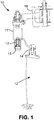
- FIG. 1 illustrates a portion of a section 10 of a gas turbine engine, such as a compressor module.
- the portion shown illustrates an inlet guide vane 12 which may be movable.
- the inlet guide vane 12 has an integrally formed stem 14 to which an actuation arm 16 is attached.
- the actuation arm 16 may be further attached to a bushing 13 via a pin 15 which is rotatable.
- the bushing 13 may be part of a ring assembly 17 which is attached to a torque box assembly 18 and which together may form a means for changing the position of the vane 12.
- the ring assembly 17 is connected to a number of actuation arms 16 circumferentially around the section 10.
- the vane arm actuation assembly includes the integrally formed vane stem 14 and the actuation arm 16. As shown in FIG. 2 and 3 , the vane stem 14 has a slot 22 formed in an end portion 24 of the vane stem 14. The vane stem 14 also has a first planar surface 26, a second planar surface 28, a top surface 30, and two angled surfaces 32 and 34. The top surface 30 has an opening 36 for receiving a threaded insert 38 having a central opening 40.
- the actuation arm 16 has a first planar portion 42 which has an opening 44 which aligns with the opening 40 in the threaded insert 38.
- the actuation arm 16 also has a slot 46 formed in an end surface 48.
- the actuation arm 16 further has an angled portion 50 which terminates in a second planar portion 52.
- the second planar portion 52 has an opening 54 for receiving a connection member, such as the pin 15, for joining the actuation arm 16 to the bushing 13.
- the underside 58 of the first planar portion is configured to mate with the surfaces 26, 28, 30, 32, and 34 of the stem 14.
- the assembly 20 further includes a tab washer 60.
- the tab washer 60 has a first portion 62 positioned over the first planar portion 42 of the actuation arm 16.
- the first portion 62 includes an opening 64 which aligns with the opening 44.
- the first portion 62 may have two spaced apart projection members 66 and 68 which abut a surface of the first planar portion 42.
- the spaced apart projection members 66 and 68 have an angled slot 70 between them.
- the washer 60 has a second portion 72 at a right angle to the first portion 62.
- the second portion 72 has a width which allows the second portion 72 to fit into the slot 46 in the side of the actuation arm 16.
- the tab washer 60 further has a tab 74 which fits into the slot 22 in the stem 14.
- the tab 74 may extend substantially parallel to the first portion 62 and may be substantially perpendicular to the second portion 72.
- the vane stem 14, the actuation arm 16, and the washer 60 may be joined together by an engagement device 76 such as a bolt.
- an engagement device 76 such as a bolt.
- the vane arm assembly described herein is a very simple, inexpensive configuration and mistake proof in its assembly.
- the custom washer 60 prevents the vane arm 16 from being misassembled.
- the assembly described herein may be used in applications where mistake proof shaft to bellcrank attachments are needed.
- the assembly may be used in helicopter, automotive, and aeroplane chassis fields.
Landscapes
- Engineering & Computer Science (AREA)
- General Engineering & Computer Science (AREA)
- Mechanical Engineering (AREA)
- Structures Of Non-Positive Displacement Pumps (AREA)
- Control Of Turbines (AREA)
- Turbine Rotor Nozzle Sealing (AREA)
Description
- The present disclosure relates to an arm assembly for operating a device such as a variable vane.
- Variable vanes in gas turbine engines are connected to an arm assembly. In the past, prior engines used a stud with a flat as part of the vane arm assembly. However, despite the use of such a stud, there is still a need for a vane arm assembly which could be mistake proofed.
-
US 5,492,446 discloses an assembly for operating a device as set forth in the preamble of claim 1. -
US 4,498,790 discloses a bushing securing apparatus. - From a first aspect, the invention provides an assembly for operating a device as set forth in claim 1.
- In an embodiment, an engagement device may be used to join the arm to the stem and the overlapping portion of the member may include an opening for receiving a portion of the engagement device.
- In another and/or alternative embodiment, the overlapping portion may have two spaced apart projection members abutting a surface of the arm and a slot between the two spaced apart projection members.
- In another and/or alternative embodiment, the arm may have a slot and the second portion may have a width so that the second portion fits within the slot.
- In another and/or alternative embodiment, the stem may have an opening in a surface and the assembly may further comprise a threaded insert fitting into the opening.
- In another and/or alternative embodiment, the stem may have angled surfaces and the arm may have a surface which mates with the angled surfaces.
- In another and/or alternative embodiment, the slot may be in an end surface of the stem.
- In another and/or alternative embodiment, the member may be a washer.
- In another and/or alternative embodiment, the device may be a variable vane.
- In another and/or alternative embodiment, the assembly may be a vane arm assembly for a gas turbine engine and the stem may be integrally formed on a vane.
- In another and/or alternative embodiment, the assembly may further comprise means for changing the position of the vane which changing means are connected to the arm.
- Other details of the vane arm assembly are set forth in the following detailed description and the accompanying drawings wherein like reference numerals depict like elements.
-
-
FIG. 1 is a schematic arrangement of a portion of a gas turbine engine and a system for operating a variable vane; -
FIG. 2 is an exploded view of a vane arm actuation assembly in accordance with the present disclosure; -
FIG. 3 is a side view of a vane stem; and -
FIG. 4 is a view illustrating the assembled vane arm actuation assembly. - Referring now to the drawings,
FIG. 1 illustrates a portion of asection 10 of a gas turbine engine, such as a compressor module. The portion shown illustrates aninlet guide vane 12 which may be movable. Theinlet guide vane 12 has an integrally formedstem 14 to which anactuation arm 16 is attached. Theactuation arm 16 may be further attached to a bushing 13 via apin 15 which is rotatable. Thebushing 13 may be part of aring assembly 17 which is attached to atorque box assembly 18 and which together may form a means for changing the position of thevane 12. Thering assembly 17 is connected to a number ofactuation arms 16 circumferentially around thesection 10. - Referring now to
FIG. 2 , there is shown an exploded embodiment of a vanearm actuation assembly 20 in accordance with the present disclosure. The vane arm actuation assembly includes the integrally formedvane stem 14 and theactuation arm 16. As shown inFIG. 2 and 3 , thevane stem 14 has aslot 22 formed in anend portion 24 of thevane stem 14. Thevane stem 14 also has a firstplanar surface 26, a secondplanar surface 28, atop surface 30, and twoangled surfaces top surface 30 has anopening 36 for receiving a threadedinsert 38 having acentral opening 40. - The
actuation arm 16 has a firstplanar portion 42 which has anopening 44 which aligns with the opening 40 in the threadedinsert 38. Theactuation arm 16 also has aslot 46 formed in anend surface 48. Theactuation arm 16 further has anangled portion 50 which terminates in a secondplanar portion 52. The secondplanar portion 52 has an opening 54 for receiving a connection member, such as thepin 15, for joining theactuation arm 16 to thebushing 13. Theunderside 58 of the first planar portion is configured to mate with thesurfaces stem 14. - The
assembly 20 further includes atab washer 60. Thetab washer 60 has afirst portion 62 positioned over the firstplanar portion 42 of theactuation arm 16. Thefirst portion 62 includes anopening 64 which aligns with the opening 44. Thefirst portion 62 may have two spaced apartprojection members planar portion 42. The spaced apartprojection members angled slot 70 between them. Thewasher 60 has asecond portion 72 at a right angle to thefirst portion 62. Thesecond portion 72 has a width which allows thesecond portion 72 to fit into theslot 46 in the side of theactuation arm 16. Thetab washer 60 further has atab 74 which fits into theslot 22 in thestem 14. Thetab 74 may extend substantially parallel to thefirst portion 62 and may be substantially perpendicular to thesecond portion 72. - As shown in
FIGS. 2 and4 , thevane stem 14, theactuation arm 16, and thewasher 60 may be joined together by anengagement device 76 such as a bolt. When the vane arm assembly is assembled, thebolt 76 passes through theopening 64 and the opening 44 and into the opening 40 in the threadedinsert 38. - The vane arm assembly described herein is a very simple, inexpensive configuration and mistake proof in its assembly. The
custom washer 60 prevents thevane arm 16 from being misassembled. - The assembly described herein may be used in applications where mistake proof shaft to bellcrank attachments are needed. Thus, the assembly may be used in helicopter, automotive, and aeroplane chassis fields.
- There has been provided herein a vane arm assembly. While the vane arm assembly has been described in the context of specific embodiments thereof, other unforeseen alternatives, modifications, and variations may become apparent to those skilled in the art having read the foregoing description. Accordingly, it is intended to embrace those alternatives, modifications, and variations as fall within the broad scope of the appended claims.
Claims (10)
- An assembly (20) for operating a device, said assembly comprising:an arm (16);a stem (14) to which said arm (16) is connected;said stem (14) having a slot (22); anda member (60) having a tab (74) which fits into said slot (22)and a first portion (62) which overlaps said arm (16), characterised in that said member (60) has a second portion (72) extending at a right angle to said first portion (62) and connecting said first portion (62) and said tab (74).
- The assembly of claim 1, wherein an engagement device (76) is used to join said arm (16) to said stem (14) and said overlapping portion (62) of said member (60) includes an opening for receiving a portion of said engagement device (76), two spaced apart projection members (66, 68) abutting a surface of said arm (16) and a slot (70) between said two spaced apart projection members (66, 68).
- The assembly of claim 1 or 2, wherein said arm (16) has a slot (46) and said second portion (72) has a width so that said second portion (72) fits within said slot (46).
- The assembly of any preceding claim, wherein said stem (14) has an opening (36) in a surface (30) and said assembly further comprises a threaded insert (38) fitting into said opening (36).
- The assembly of any preceding claim, wherein said stem (14) has angled surfaces (32, 34) and said arm (16) has a surface which mates with said angled surfaces (32, 34).
- The assembly of any preceding claim, wherein said slot (22) is in an end surface (24) of said stem (14).
- The assembly of any preceding claim, wherein said member (60) is a washer.
- The assembly of any preceding claim, wherein said device is a variable vane.
- The assembly of any preceding claim, the assembly being a vane arm assembly for a gas turbine engine,
said stem (14) being integrally formed on a vane (12). - The assembly of claim 9, further comprising means for changing the position of said vane (12) and said changing means being connected to said arm (16).
Applications Claiming Priority (2)
| Application Number | Priority Date | Filing Date | Title |
|---|---|---|---|
| US201361868738P | 2013-08-22 | 2013-08-22 | |
| PCT/US2014/040814 WO2015026420A1 (en) | 2013-08-22 | 2014-06-04 | Vane arm assembly |
Publications (3)
| Publication Number | Publication Date |
|---|---|
| EP3036407A1 EP3036407A1 (en) | 2016-06-29 |
| EP3036407A4 EP3036407A4 (en) | 2016-09-21 |
| EP3036407B1 true EP3036407B1 (en) | 2020-11-11 |
Family
ID=52484031
Family Applications (1)
| Application Number | Title | Priority Date | Filing Date |
|---|---|---|---|
| EP14838674.1A Active EP3036407B1 (en) | 2013-08-22 | 2014-06-04 | Vane arm assembly |
Country Status (3)
| Country | Link |
|---|---|
| US (1) | US10253646B2 (en) |
| EP (1) | EP3036407B1 (en) |
| WO (1) | WO2015026420A1 (en) |
Cited By (1)
| Publication number | Priority date | Publication date | Assignee | Title |
|---|---|---|---|---|
| US12618334B2 (en) | 2023-08-08 | 2026-05-05 | MTU Aero Engines AG | Stator vane assembly of a turbomachine and method for assembling a stator vane assembly |
Families Citing this family (7)
| Publication number | Priority date | Publication date | Assignee | Title |
|---|---|---|---|---|
| US9988926B2 (en) | 2013-03-13 | 2018-06-05 | United Technologies Corporation | Machined vane arm of a variable vane actuation system |
| US10030582B2 (en) * | 2015-02-09 | 2018-07-24 | United Technologies Corporation | Orientation feature for swirler tube |
| US10815818B2 (en) * | 2017-07-18 | 2020-10-27 | Raytheon Technologies Corporation | Variable-pitch vane assembly |
| US10590795B2 (en) * | 2017-10-17 | 2020-03-17 | United Technologies Corporation | Vane arm with tri-wedge circular pocket |
| DE102017222209A1 (en) * | 2017-12-07 | 2019-06-13 | MTU Aero Engines AG | Guide vane connection and turbomachine |
| US11008879B2 (en) * | 2019-01-18 | 2021-05-18 | Raytheon Technologies Corporation | Continuous wedge vane arm with failsafe retention clip |
| US10837309B2 (en) * | 2019-04-09 | 2020-11-17 | Raytheon Technologies Corporation | Retention clip for variable vane arm |
Family Cites Families (9)
| Publication number | Priority date | Publication date | Assignee | Title |
|---|---|---|---|---|
| US4498790A (en) | 1983-11-21 | 1985-02-12 | United Technologies Corporation | Bushing securing apparatus |
| US5492446A (en) * | 1994-12-15 | 1996-02-20 | General Electric Company | Self-aligning variable stator vane |
| US6209198B1 (en) * | 1998-12-16 | 2001-04-03 | General Electric Company | Method of assembling a variable stator vane assembly |
| US6682299B2 (en) * | 2001-11-15 | 2004-01-27 | General Electric Company | Variable stator vane support arrangement |
| FR2835562B1 (en) | 2002-02-07 | 2004-07-16 | Snecma Moteurs | STATOR BLADE SWIVEL ARRANGEMENT IN A TURBOMACHINE |
| US6984104B2 (en) | 2002-12-16 | 2006-01-10 | United Technologies Corporation | Variable vane arm/unison ring attachment system |
| US7011494B2 (en) | 2004-02-04 | 2006-03-14 | United Technologies Corporation | Dual retention vane arm |
| US8215902B2 (en) * | 2008-10-15 | 2012-07-10 | United Technologies Corporation | Scalable high pressure compressor variable vane actuation arm |
| US8414248B2 (en) * | 2008-12-30 | 2013-04-09 | Rolls-Royce Corporation | Variable geometry vane |
-
2014
- 2014-06-04 EP EP14838674.1A patent/EP3036407B1/en active Active
- 2014-06-04 US US14/913,043 patent/US10253646B2/en active Active
- 2014-06-04 WO PCT/US2014/040814 patent/WO2015026420A1/en not_active Ceased
Non-Patent Citations (1)
| Title |
|---|
| None * |
Cited By (1)
| Publication number | Priority date | Publication date | Assignee | Title |
|---|---|---|---|---|
| US12618334B2 (en) | 2023-08-08 | 2026-05-05 | MTU Aero Engines AG | Stator vane assembly of a turbomachine and method for assembling a stator vane assembly |
Also Published As
| Publication number | Publication date |
|---|---|
| US10253646B2 (en) | 2019-04-09 |
| EP3036407A1 (en) | 2016-06-29 |
| US20160201499A1 (en) | 2016-07-14 |
| WO2015026420A1 (en) | 2015-02-26 |
| EP3036407A4 (en) | 2016-09-21 |
Similar Documents
| Publication | Publication Date | Title |
|---|---|---|
| US10253646B2 (en) | Vane arm assembly | |
| US6843638B2 (en) | Vane radial mounting apparatus | |
| US9284969B2 (en) | Thermal expansion joint connection for sheet metal assembly | |
| CN108930611B (en) | Method for manufacturing and assembling thrust reverser cascades | |
| US9835165B2 (en) | Turbine housing assembly and manufacturing method of turbine housing assembly | |
| US8226357B2 (en) | Pitch control ring for stator vanes of a turbomachine | |
| JP5134717B1 (en) | Variable capacity turbocharger and variable nozzle mechanism assembly method | |
| KR102265942B1 (en) | Annular turbine engine combustion chamber | |
| US10570814B2 (en) | Waste-gate valve and turbocharger | |
| US20180363493A1 (en) | Nozzle drive mechanism, turbocharger, and variable-capacity turbocharger | |
| US20140109592A1 (en) | Leaf spring hanger for exhaust duct liner | |
| KR20180054652A (en) | Geometry to increase the torque capacity of the rivet vane lever | |
| US10233828B2 (en) | Variable nozzle unit and variable geometry system turbocharger | |
| US11713142B2 (en) | Separation device assemblies | |
| US9157537B2 (en) | Aircraft fluid check valve assembly with indexing | |
| EP3971404B1 (en) | Exhaust duct of gas turbine engine | |
| US9416682B2 (en) | Turbine engine alignment assembly | |
| US8794916B2 (en) | Shroud supporting structure for gas turbine engine | |
| EP3650708B1 (en) | Compressor inlet adjustment mechanism | |
| JP2009008257A (en) | Coupling system comprising safety fastener means | |
| US11713709B2 (en) | Nozzle device and exhaust turbocharger | |
| US10036282B2 (en) | Vane support systems | |
| CN104334851B (en) | For the bayonet type spacer retention system of variable turbine geometry blade group | |
| US9133724B2 (en) | Turbomachine component including a cover plate | |
| JP6490394B2 (en) | Duct apparatus and associated method for use with an aircraft |
Legal Events
| Date | Code | Title | Description |
|---|---|---|---|
| PUAI | Public reference made under article 153(3) epc to a published international application that has entered the european phase |
Free format text: ORIGINAL CODE: 0009012 |
|
| 17P | Request for examination filed |
Effective date: 20160304 |
|
| AK | Designated contracting states |
Kind code of ref document: A1 Designated state(s): AL AT BE BG CH CY CZ DE DK EE ES FI FR GB GR HR HU IE IS IT LI LT LU LV MC MK MT NL NO PL PT RO RS SE SI SK SM TR |
|
| AX | Request for extension of the european patent |
Extension state: BA ME |
|
| A4 | Supplementary search report drawn up and despatched |
Effective date: 20160824 |
|
| RIC1 | Information provided on ipc code assigned before grant |
Ipc: F16B 21/16 20060101ALI20160818BHEP Ipc: F04D 29/64 20060101ALI20160818BHEP Ipc: F01D 17/16 20060101AFI20160818BHEP Ipc: F04D 29/56 20060101ALI20160818BHEP |
|
| RAP1 | Party data changed (applicant data changed or rights of an application transferred) |
Owner name: UNITED TECHNOLOGIES CORPORATION |
|
| DAX | Request for extension of the european patent (deleted) | ||
| GRAP | Despatch of communication of intention to grant a patent |
Free format text: ORIGINAL CODE: EPIDOSNIGR1 |
|
| STAA | Information on the status of an ep patent application or granted ep patent |
Free format text: STATUS: GRANT OF PATENT IS INTENDED |
|
| RIC1 | Information provided on ipc code assigned before grant |
Ipc: F04D 29/64 20060101ALI20200513BHEP Ipc: F16B 43/02 20060101ALI20200513BHEP Ipc: F16B 9/02 20060101ALI20200513BHEP Ipc: F16B 1/00 20060101ALI20200513BHEP Ipc: F16B 21/16 20060101ALI20200513BHEP Ipc: F01D 17/16 20060101AFI20200513BHEP Ipc: F04D 29/56 20060101ALI20200513BHEP |
|
| INTG | Intention to grant announced |
Effective date: 20200603 |
|
| GRAS | Grant fee paid |
Free format text: ORIGINAL CODE: EPIDOSNIGR3 |
|
| GRAA | (expected) grant |
Free format text: ORIGINAL CODE: 0009210 |
|
| STAA | Information on the status of an ep patent application or granted ep patent |
Free format text: STATUS: THE PATENT HAS BEEN GRANTED |
|
| AK | Designated contracting states |
Kind code of ref document: B1 Designated state(s): AL AT BE BG CH CY CZ DE DK EE ES FI FR GB GR HR HU IE IS IT LI LT LU LV MC MK MT NL NO PL PT RO RS SE SI SK SM TR |
|
| REG | Reference to a national code |
Ref country code: GB Ref legal event code: FG4D |
|
| REG | Reference to a national code |
Ref country code: CH Ref legal event code: EP |
|
| REG | Reference to a national code |
Ref country code: AT Ref legal event code: REF Ref document number: 1333673 Country of ref document: AT Kind code of ref document: T Effective date: 20201115 |
|
| REG | Reference to a national code |
Ref country code: DE Ref legal event code: R096 Ref document number: 602014072329 Country of ref document: DE |
|
| REG | Reference to a national code |
Ref country code: IE Ref legal event code: FG4D |
|
| RAP2 | Party data changed (patent owner data changed or rights of a patent transferred) |
Owner name: RAYTHEON TECHNOLOGIES CORPORATION |
|
| REG | Reference to a national code |
Ref country code: NL Ref legal event code: MP Effective date: 20201111 |
|
| REG | Reference to a national code |
Ref country code: AT Ref legal event code: MK05 Ref document number: 1333673 Country of ref document: AT Kind code of ref document: T Effective date: 20201111 |
|
| PG25 | Lapsed in a contracting state [announced via postgrant information from national office to epo] |
Ref country code: GR Free format text: LAPSE BECAUSE OF FAILURE TO SUBMIT A TRANSLATION OF THE DESCRIPTION OR TO PAY THE FEE WITHIN THE PRESCRIBED TIME-LIMIT Effective date: 20210212 Ref country code: NO Free format text: LAPSE BECAUSE OF FAILURE TO SUBMIT A TRANSLATION OF THE DESCRIPTION OR TO PAY THE FEE WITHIN THE PRESCRIBED TIME-LIMIT Effective date: 20210211 Ref country code: PT Free format text: LAPSE BECAUSE OF FAILURE TO SUBMIT A TRANSLATION OF THE DESCRIPTION OR TO PAY THE FEE WITHIN THE PRESCRIBED TIME-LIMIT Effective date: 20210311 Ref country code: FI Free format text: LAPSE BECAUSE OF FAILURE TO SUBMIT A TRANSLATION OF THE DESCRIPTION OR TO PAY THE FEE WITHIN THE PRESCRIBED TIME-LIMIT Effective date: 20201111 Ref country code: RS Free format text: LAPSE BECAUSE OF FAILURE TO SUBMIT A TRANSLATION OF THE DESCRIPTION OR TO PAY THE FEE WITHIN THE PRESCRIBED TIME-LIMIT Effective date: 20201111 |
|
| PG25 | Lapsed in a contracting state [announced via postgrant information from national office to epo] |
Ref country code: AT Free format text: LAPSE BECAUSE OF FAILURE TO SUBMIT A TRANSLATION OF THE DESCRIPTION OR TO PAY THE FEE WITHIN THE PRESCRIBED TIME-LIMIT Effective date: 20201111 Ref country code: BG Free format text: LAPSE BECAUSE OF FAILURE TO SUBMIT A TRANSLATION OF THE DESCRIPTION OR TO PAY THE FEE WITHIN THE PRESCRIBED TIME-LIMIT Effective date: 20210211 Ref country code: IS Free format text: LAPSE BECAUSE OF FAILURE TO SUBMIT A TRANSLATION OF THE DESCRIPTION OR TO PAY THE FEE WITHIN THE PRESCRIBED TIME-LIMIT Effective date: 20210311 Ref country code: SE Free format text: LAPSE BECAUSE OF FAILURE TO SUBMIT A TRANSLATION OF THE DESCRIPTION OR TO PAY THE FEE WITHIN THE PRESCRIBED TIME-LIMIT Effective date: 20201111 Ref country code: LV Free format text: LAPSE BECAUSE OF FAILURE TO SUBMIT A TRANSLATION OF THE DESCRIPTION OR TO PAY THE FEE WITHIN THE PRESCRIBED TIME-LIMIT Effective date: 20201111 Ref country code: PL Free format text: LAPSE BECAUSE OF FAILURE TO SUBMIT A TRANSLATION OF THE DESCRIPTION OR TO PAY THE FEE WITHIN THE PRESCRIBED TIME-LIMIT Effective date: 20201111 |
|
| REG | Reference to a national code |
Ref country code: LT Ref legal event code: MG9D |
|
| PG25 | Lapsed in a contracting state [announced via postgrant information from national office to epo] |
Ref country code: HR Free format text: LAPSE BECAUSE OF FAILURE TO SUBMIT A TRANSLATION OF THE DESCRIPTION OR TO PAY THE FEE WITHIN THE PRESCRIBED TIME-LIMIT Effective date: 20201111 |
|
| PG25 | Lapsed in a contracting state [announced via postgrant information from national office to epo] |
Ref country code: LT Free format text: LAPSE BECAUSE OF FAILURE TO SUBMIT A TRANSLATION OF THE DESCRIPTION OR TO PAY THE FEE WITHIN THE PRESCRIBED TIME-LIMIT Effective date: 20201111 Ref country code: SK Free format text: LAPSE BECAUSE OF FAILURE TO SUBMIT A TRANSLATION OF THE DESCRIPTION OR TO PAY THE FEE WITHIN THE PRESCRIBED TIME-LIMIT Effective date: 20201111 Ref country code: RO Free format text: LAPSE BECAUSE OF FAILURE TO SUBMIT A TRANSLATION OF THE DESCRIPTION OR TO PAY THE FEE WITHIN THE PRESCRIBED TIME-LIMIT Effective date: 20201111 Ref country code: CZ Free format text: LAPSE BECAUSE OF FAILURE TO SUBMIT A TRANSLATION OF THE DESCRIPTION OR TO PAY THE FEE WITHIN THE PRESCRIBED TIME-LIMIT Effective date: 20201111 Ref country code: EE Free format text: LAPSE BECAUSE OF FAILURE TO SUBMIT A TRANSLATION OF THE DESCRIPTION OR TO PAY THE FEE WITHIN THE PRESCRIBED TIME-LIMIT Effective date: 20201111 Ref country code: SM Free format text: LAPSE BECAUSE OF FAILURE TO SUBMIT A TRANSLATION OF THE DESCRIPTION OR TO PAY THE FEE WITHIN THE PRESCRIBED TIME-LIMIT Effective date: 20201111 |
|
| REG | Reference to a national code |
Ref country code: DE Ref legal event code: R097 Ref document number: 602014072329 Country of ref document: DE |
|
| PG25 | Lapsed in a contracting state [announced via postgrant information from national office to epo] |
Ref country code: DK Free format text: LAPSE BECAUSE OF FAILURE TO SUBMIT A TRANSLATION OF THE DESCRIPTION OR TO PAY THE FEE WITHIN THE PRESCRIBED TIME-LIMIT Effective date: 20201111 |
|
| PLBE | No opposition filed within time limit |
Free format text: ORIGINAL CODE: 0009261 |
|
| STAA | Information on the status of an ep patent application or granted ep patent |
Free format text: STATUS: NO OPPOSITION FILED WITHIN TIME LIMIT |
|
| 26N | No opposition filed |
Effective date: 20210812 |
|
| PG25 | Lapsed in a contracting state [announced via postgrant information from national office to epo] |
Ref country code: IT Free format text: LAPSE BECAUSE OF FAILURE TO SUBMIT A TRANSLATION OF THE DESCRIPTION OR TO PAY THE FEE WITHIN THE PRESCRIBED TIME-LIMIT Effective date: 20201111 Ref country code: NL Free format text: LAPSE BECAUSE OF FAILURE TO SUBMIT A TRANSLATION OF THE DESCRIPTION OR TO PAY THE FEE WITHIN THE PRESCRIBED TIME-LIMIT Effective date: 20201111 Ref country code: AL Free format text: LAPSE BECAUSE OF FAILURE TO SUBMIT A TRANSLATION OF THE DESCRIPTION OR TO PAY THE FEE WITHIN THE PRESCRIBED TIME-LIMIT Effective date: 20201111 |
|
| PG25 | Lapsed in a contracting state [announced via postgrant information from national office to epo] |
Ref country code: SI Free format text: LAPSE BECAUSE OF FAILURE TO SUBMIT A TRANSLATION OF THE DESCRIPTION OR TO PAY THE FEE WITHIN THE PRESCRIBED TIME-LIMIT Effective date: 20201111 Ref country code: ES Free format text: LAPSE BECAUSE OF FAILURE TO SUBMIT A TRANSLATION OF THE DESCRIPTION OR TO PAY THE FEE WITHIN THE PRESCRIBED TIME-LIMIT Effective date: 20201111 |
|
| PG25 | Lapsed in a contracting state [announced via postgrant information from national office to epo] |
Ref country code: MC Free format text: LAPSE BECAUSE OF FAILURE TO SUBMIT A TRANSLATION OF THE DESCRIPTION OR TO PAY THE FEE WITHIN THE PRESCRIBED TIME-LIMIT Effective date: 20201111 |
|
| REG | Reference to a national code |
Ref country code: CH Ref legal event code: PL |
|
| REG | Reference to a national code |
Ref country code: BE Ref legal event code: MM Effective date: 20210630 |
|
| PG25 | Lapsed in a contracting state [announced via postgrant information from national office to epo] |
Ref country code: LU Free format text: LAPSE BECAUSE OF NON-PAYMENT OF DUE FEES Effective date: 20210604 |
|
| PG25 | Lapsed in a contracting state [announced via postgrant information from national office to epo] |
Ref country code: LI Free format text: LAPSE BECAUSE OF NON-PAYMENT OF DUE FEES Effective date: 20210630 Ref country code: IE Free format text: LAPSE BECAUSE OF NON-PAYMENT OF DUE FEES Effective date: 20210604 Ref country code: CH Free format text: LAPSE BECAUSE OF NON-PAYMENT OF DUE FEES Effective date: 20210630 |
|
| PG25 | Lapsed in a contracting state [announced via postgrant information from national office to epo] |
Ref country code: IS Free format text: LAPSE BECAUSE OF FAILURE TO SUBMIT A TRANSLATION OF THE DESCRIPTION OR TO PAY THE FEE WITHIN THE PRESCRIBED TIME-LIMIT Effective date: 20210311 |
|
| PG25 | Lapsed in a contracting state [announced via postgrant information from national office to epo] |
Ref country code: BE Free format text: LAPSE BECAUSE OF NON-PAYMENT OF DUE FEES Effective date: 20210630 |
|
| PG25 | Lapsed in a contracting state [announced via postgrant information from national office to epo] |
Ref country code: HU Free format text: LAPSE BECAUSE OF FAILURE TO SUBMIT A TRANSLATION OF THE DESCRIPTION OR TO PAY THE FEE WITHIN THE PRESCRIBED TIME-LIMIT; INVALID AB INITIO Effective date: 20140604 |
|
| P01 | Opt-out of the competence of the unified patent court (upc) registered |
Effective date: 20230520 |
|
| PG25 | Lapsed in a contracting state [announced via postgrant information from national office to epo] |
Ref country code: CY Free format text: LAPSE BECAUSE OF FAILURE TO SUBMIT A TRANSLATION OF THE DESCRIPTION OR TO PAY THE FEE WITHIN THE PRESCRIBED TIME-LIMIT Effective date: 20201111 |
|
| PG25 | Lapsed in a contracting state [announced via postgrant information from national office to epo] |
Ref country code: MK Free format text: LAPSE BECAUSE OF FAILURE TO SUBMIT A TRANSLATION OF THE DESCRIPTION OR TO PAY THE FEE WITHIN THE PRESCRIBED TIME-LIMIT Effective date: 20201111 |
|
| PG25 | Lapsed in a contracting state [announced via postgrant information from national office to epo] |
Ref country code: MT Free format text: LAPSE BECAUSE OF FAILURE TO SUBMIT A TRANSLATION OF THE DESCRIPTION OR TO PAY THE FEE WITHIN THE PRESCRIBED TIME-LIMIT Effective date: 20201111 |
|
| PGFP | Annual fee paid to national office [announced via postgrant information from national office to epo] |
Ref country code: DE Payment date: 20250520 Year of fee payment: 12 |
|
| PGFP | Annual fee paid to national office [announced via postgrant information from national office to epo] |
Ref country code: GB Payment date: 20250520 Year of fee payment: 12 |
|
| PGFP | Annual fee paid to national office [announced via postgrant information from national office to epo] |
Ref country code: FR Payment date: 20250520 Year of fee payment: 12 |
|
| REG | Reference to a national code |
Ref country code: DE Ref legal event code: R081 Ref document number: 602014072329 Country of ref document: DE Owner name: RTX CORPORATION (N.D.GES.D. STAATES DELAWARE),, US Free format text: FORMER OWNER: UNITED TECHNOLOGIES CORPORATION, FARMINGTON, CONN., US |
|
| PG25 | Lapsed in a contracting state [announced via postgrant information from national office to epo] |
Ref country code: TR Free format text: LAPSE BECAUSE OF FAILURE TO SUBMIT A TRANSLATION OF THE DESCRIPTION OR TO PAY THE FEE WITHIN THE PRESCRIBED TIME-LIMIT Effective date: 20201111 |