EP3036171B1 - Covers and containment systems and methods for food service pans - Google Patents
Covers and containment systems and methods for food service pans Download PDFInfo
- Publication number
- EP3036171B1 EP3036171B1 EP14837274.1A EP14837274A EP3036171B1 EP 3036171 B1 EP3036171 B1 EP 3036171B1 EP 14837274 A EP14837274 A EP 14837274A EP 3036171 B1 EP3036171 B1 EP 3036171B1
- Authority
- EP
- European Patent Office
- Prior art keywords
- pan
- cover
- food
- panel
- gusset
- Prior art date
- Legal status (The legal status is an assumption and is not a legal conclusion. Google has not performed a legal analysis and makes no representation as to the accuracy of the status listed.)
- Active
Links
Images
















Classifications
-
- A—HUMAN NECESSITIES
- A47—FURNITURE; DOMESTIC ARTICLES OR APPLIANCES; COFFEE MILLS; SPICE MILLS; SUCTION CLEANERS IN GENERAL
- A47J—KITCHEN EQUIPMENT; COFFEE MILLS; SPICE MILLS; APPARATUS FOR MAKING BEVERAGES
- A47J36/00—Parts, details or accessories of cooking-vessels
- A47J36/06—Lids or covers for cooking-vessels
-
- A—HUMAN NECESSITIES
- A47—FURNITURE; DOMESTIC ARTICLES OR APPLIANCES; COFFEE MILLS; SPICE MILLS; SUCTION CLEANERS IN GENERAL
- A47J—KITCHEN EQUIPMENT; COFFEE MILLS; SPICE MILLS; APPARATUS FOR MAKING BEVERAGES
- A47J36/00—Parts, details or accessories of cooking-vessels
- A47J36/02—Selection of specific materials, e.g. heavy bottoms with copper inlay or with insulating inlay
- A47J36/022—Cooking- or baking-vessels or supports thereof for using only once
-
- A—HUMAN NECESSITIES
- A47—FURNITURE; DOMESTIC ARTICLES OR APPLIANCES; COFFEE MILLS; SPICE MILLS; SUCTION CLEANERS IN GENERAL
- A47J—KITCHEN EQUIPMENT; COFFEE MILLS; SPICE MILLS; APPARATUS FOR MAKING BEVERAGES
- A47J36/00—Parts, details or accessories of cooking-vessels
- A47J36/02—Selection of specific materials, e.g. heavy bottoms with copper inlay or with insulating inlay
- A47J36/027—Cooking- or baking-vessels specially adapted for use in microwave ovens; Accessories therefor
-
- B—PERFORMING OPERATIONS; TRANSPORTING
- B65—CONVEYING; PACKING; STORING; HANDLING THIN OR FILAMENTARY MATERIAL
- B65D—CONTAINERS FOR STORAGE OR TRANSPORT OF ARTICLES OR MATERIALS, e.g. BAGS, BARRELS, BOTTLES, BOXES, CANS, CARTONS, CRATES, DRUMS, JARS, TANKS, HOPPERS, FORWARDING CONTAINERS; ACCESSORIES, CLOSURES, OR FITTINGS THEREFOR; PACKAGING ELEMENTS; PACKAGES
- B65D81/00—Containers, packaging elements, or packages, for contents presenting particular transport or storage problems, or adapted to be used for non-packaging purposes after removal of contents
- B65D81/34—Containers, packaging elements, or packages, for contents presenting particular transport or storage problems, or adapted to be used for non-packaging purposes after removal of contents for packaging foodstuffs or other articles intended to be cooked or heated within the package
- B65D81/343—Containers, packaging elements, or packages, for contents presenting particular transport or storage problems, or adapted to be used for non-packaging purposes after removal of contents for packaging foodstuffs or other articles intended to be cooked or heated within the package specially adapted to be heated in a conventional oven, e.g. a gas or electric resistance oven
Definitions
- the present disclosure relates to covers for food service pans and food containment systems. More specifically, the present disclosure relates to ovenable, heat-shrinkable covers for food service pans and food containment systems.
- Large food service pans are used for cooking, serving, and storing food in commercial food service establishments. These pans can be used in food servers, such as steam tables, buffet tables, chill tables, salad bars, chafing dishes, and the like. These pans can be used, for example, to cook and heat food, store food, and/or as transfer pans to carry large portions of food to and from a serving area.
- Conventional metal (e.g., stainless steel) food service pans are available in a variety of shapes, including rectangular and circular shapes.
- Such pans typically have a flange extending around a peripheral edge of the open pan top. The flange supports the pan in a steam or buffet table, provides a steam seal around a steam table, and offers a convenient lifting and carrying point.
- the pan body e.g., the food receptacle portion
- flange When used in a steam table, buffet table, salad bar, or the like, the pan body (e.g., the food receptacle portion) and flange are typically dimensioned so that the receptacle is received into an opening in the table or bar and supported by its flange resting upon the edges of the table or bar opening.
- covers Difficulties with such conventional covers include tearing, breaking, leaking, and the inability to stack the pans in a refrigerator, walk-in box, or in transport.
- many covers are not ovenable (i.e., the cover cannot be subjected to cooking temperatures without melting, cracking or contaminating food).
- metal foils are notoriously easy to puncture and tear (e.g., by serving utensils). Further, metal foils are opaque and do not allow easy viewing of the contents of the container. They also cannot be heated in a microwave oven.
- sheets of metallic materials are relatively expensive as compared to other materials.
- paper sheets are useful for some culinary purposes, they are not ideal for pan covering because they are easily torn, are moisture and air permeable, and do not seal well around pans. In addition, paper sheets are typically not suitable for high temperature cooking applications.
- Thermoplastic films such as polyethylene films, offer greater durability.
- a problem with conventional films is that they typically do not grip or cling well to a pan edge, thereby allowing spillage, leakage, or spoilage.
- many thermoplastic films are not ovenable and, therefore, cannot be used when reheating or cooking food in the pan. Some films even emit dangerous chemicals when heated.
- Still another disadvantage of these conventional pan covering methods is frequent worker injury. Covering a pan typically involves pulling a plastic sheet or metal foil from a roll and forcing the sheet or foil against a serrated metal cutter edge to remove a desired length of the plastic sheet or foil. When moving quickly, as workers in a commercial kitchen are often required to do, a worker can cut his or her finger or hand on the cutter edge. Such a cut is an undesirable incident in a food service environment.
- pan covering methods do not provide a quick and simple way to remove the pan covering(s) from the pan. Often, multiple layers must be unwrapped, without an easy gripping point to remove the cover.
- pan covers that provide moisture retention, reduce leakage, and allow multiple pans to be stacked on top of each other.
- US2006/191985 discloses an erectable and collapsible container including a plurality of side walls joined along a plurality of wall hinges providing articulation between the side walls.
- a bottom wall is attached to the side walls at edge hinges providing articulation between the side walls and the bottom wall.
- At least one flexible gusset portion is provided extending between one or more of the side walls and the bottom wall, and the gusset portion is movable with the bottom wall in response to movement of the side walls and the bottom wall between collapsed and erected configurations.
- Structure is provided for maintaining the side walls in the erected configuration such that the side walls define a generally rigid or semi-rigid structure.
- a pair of opposed flexible panels extend from the side walls and define a bag-like upper portion extending from the support structure and forming a sealable opening for the container.
- the present disclosure is directed to covers for food service pans, food containment systems, and methods of covering and sealing food pans.
- the food pan cover can be a bag-like structure having a closed top, an open bottom, and two sealed sides.
- the cover is pre-shaped by, for example, thermoforming to fit a pan.
- the food pan cover can be formed from a single layer of polymeric material that is heat shrinkable.
- the polymeric material is ovenable and safe for contact with food at cooking temperatures.
- the cover can withstand a temperature of at least about 204 degrees Celsius (400 degrees Fahrenheit) for a minimum of about two hours, preferably about four hours, and most preferably at least about six hours.
- the cover is at least partially transparent, such that the contents of the pan can be viewed through the cover.
- Various embodiments of the cover are disclosed. Certain embodiments provide manufacturing advantages (e.g., lower cost) while others provide better sealing to a particular pan shape and size.
- the food pan cover has a closed top end having a first top edge and an open bottom end having a first bottom edge and a second bottom edge.
- the food pan cover also has a first side seal extending from the top end to the bottom end and a second side seal extending from the top end to the bottom end.
- a first lateral wall is formed by the first top edge, first bottom edge, first side seal, and second side seal.
- a second lateral wall is formed by the first top edge, second bottom edge, first side seal, and second side seal.
- the food pan cover also includes a first angled seal extending from the first side seal to the first top edge and a second angled seal extending from the second side seal to the first top edge.
- the top end can include a second top edge.
- the first lateral wall is formed by the first top edge, first bottom edge, first side seal, and second side seal.
- the second lateral wall is formed by the second top edge, second bottom edge, first side seal, and second side seal.
- the food pan cover can include a gusset.
- the gusset is formed between the first top edge and the second top edge.
- the gusset includes a fold line, a first top panel bounded by the first top edge and the fold line, and a second top panel bounded by the second top edge and the fold line.
- each of the first and second lateral walls include a first angled seal extending from the first side seal to the respective top edge and a second angled seal extending from the second side seal to the respective top edge.
- the food pan cover can have a closed top end having a first top edge and a second top edge and an open bottom end having a first bottom edge and a second bottom edge.
- the food pan cover has a first side seal extending from the top end to the bottom end and a second side seal extending from the top end to the bottom end.
- a first lateral wall is formed by the first top edge, first bottom edge, first side seal, and second side seal.
- a second lateral wall is formed by the second top edge, second bottom edge, first side seal, and second side seal.
- a gusset is formed between the first top edge and the second top edge.
- the gusset includes a fold line, a first top panel bounded by the first top edge and the fold line, and a second top panel bounded by the second top edge and the fold line.
- the gusset can expand to increase a distance between the first lateral wall and the second lateral wall.
- the first top panel is approximately equal in size to the first lateral wall
- the second top panel is approximately equal in size to the second lateral wall.
- a food pan cover formed from a heat-shrinkable material has a first end, a second end, a first side panel having a first top edge and a first bottom edge, and a second side panel having a second top edge and a second bottom edge.
- a gusset is formed between the first side panel and the second side panel.
- the gusset has a third bottom edge, a first gusset panel delineated by the first end, the second end, the first top edge, and the third bottom edge, and a second gusset panel delineated by the first end, the second end, the second top edge, and the third bottom edge.
- a width of the first gusset panel is greater than a width of the first side panel, and a width of the second gusset panel is greater than a width of the second side panel.
- the food pan cover can be used with a Gastronorm pan to form a food containment system.
- the food pan cover has a first side seal extending along a portion of the first end, sealing together a portion of each of the first side panel, the second side panel, the first gusset panel, and the second gusset panel.
- the food pan cover also has a second side seal extending along a portion of the second end, sealing together a portion of each of the first side panel, the second side panel, the first gusset panel, and the second gusset panel.
- the first end can have a sealed portion and an unsealed portion. After heat-shrinking the food pan cover over the opening of a pan, the unsealed portion of the first end can form a first flap and a second flap. The unsealed portion of the first end can also have a first tab. The second end can also have a sealed portion and an unsealed portion. After heat-shrinking the food pan cover over the opening of a pan, the unsealed portion of the second end can form a third flap and a fourth flap. The unsealed portion of the second end can also have a second tab.
- At least one of the first or second side seal extends along more than half the width of the first or second side panel. In other embodiments, at least one of the first or second side seal extends along less than half the width of the first or second side panel. In certain embodiments, at least one of the first or second side seal extends along approximately half the width of the first or second side panel.
- At least one of the first or second side seal extends along more than half the width of the first or second gusset panel. In other embodiments, at least one of the first or second side seal extends along less than half the width of the first or second gusset panel. In certain embodiments, at least one of the first or second side seal extends along approximately half the width of the first or second gusset panel.
- the width of the first side panel is approximately equal to the width of the second side panel.
- the width of the first gusset panel can be approximately equal to the width of the second gusset panel.
- the heat-shrinkable material can be a polymeric material. In certain embodiments, the heat-shrinkable material can be a mono-layer film having a thickness of about one mil. In certain embodiments, the heat-shrinkable material is capable of withstanding a temperature of at least about 204 degrees Celsius (400 degrees Fahrenheit) for at least about two hours.
- the food pan cover is sized to fit about a Gastronorm pan.
- the pan can have a bottom surface and one or more side walls extending upwardly from the bottom surface, each side wall having a top edge defining a top opening of the pan.
- at least a portion of the first side panel of the food pan cover can be located outside a first side wall of the pan and at least a portion of the second side panel can be located outside a second side wall of the pan, when the pan cover is covering the pan.
- the pan cover can be configured to shrink when heat is applied to the pan cover so that the pan cover engages a peripheral lip of the pan at the top opening to cover and seal the top opening.
- the Gastronorm pan can be a shallow, medium, or deep third pan.
- the food pan cover can have a length between 482.6 and 533.4 mm (19 and 21 inches), and the width of the first and second gusset panels can be between 127 and 177.8 mm (5 and 7 inches). In certain embodiments, the width of the first and second side panels can be between 101.6 and 127 mm (4 and 5 inches).
- the polymeric material of the food pan cover can be substantially clear (i.e., transparent or translucent) to allow the contents of a pan to be viewed through the cover.
- Labeling information e.g., contents, date, etc.
- the food pan cover can include a first angled seal extending from the first side seal to the first top edge and a second angled seal extending from the second side seal to the first top edge.
- the food pan cover also includes a third angled seal extending from the first side seal to the second top edge and a fourth angled seal extending from the second side seal to the second top edge.
- the food pan cover can be tinted different colors using pigments, dyes, etc.
- the coloring can be for aesthetic purposes or to provide a color coding system to indicate, for example, the type of food contained within the pan.
- the cover can be translucent even with the coloring, so that the contents of the pan can still be viewed.
- various information can be printed on the covers.
- the name, address, or website of a kitchen or restaurant can be printed on the covers.
- Expiration dates, food preparation instructions, bar codes, etc. can also be printed on the covers.
- labels can be applied to the covers with similar information.
- the covers can include perforations.
- the perforations can be small pin holes that allow steam to escape from the pan during cooking, which can help control the quality of the food being cooked. For example, when cooking meat, allowing steam to escape can help the meat properly brown.
- tear locations can be added to the covers.
- one or more tear notches can be located along the sides, edges, or seals of the cover. Tear notches can make it easier to remove the cover from the pan after cooking, without requiring the use of a knife, scissors, etc.
- the food pan cover is pre-formed into a shape to match the shape of the open end of a pan to be covered.
- Food containment systems comprise the features of claim 1.
- the food containment system includes a Gastronorm pan and a food pan cover configured to fit about the Gastronorm pan.
- the food pan cover can be formed from a heat-shrinkable polymeric material capable of withstanding a temperature of at least about 204 degrees Celsius (400 degrees Fahrenheit) for at least about two hours.
- the food pan cover has a first end, a second end, a first side panel having a first top edge and a first bottom edge, and a second side panel having a second top edge and a second bottom edge.
- a gusset is formed between the first side panel and the second side panel.
- the gusset has a third bottom edge, a first gusset panel delineated by the first end, the second end, the first top edge, and the third bottom edge, and a second gusset panel delineated by the first end, the second end, the second top edge, and the third bottom edge.
- a width of the first gusset panel is greater than a width of the first side panel, and a width of the second gusset panel is greater than a width of the second side panel.
- the food pan cover has a first side seal extending along a portion of the first end, sealing together a portion of each of the first side panel, the second side panel, the first gusset panel, and the second gusset panel.
- the food pan cover also has a second side seal extending along a portion of the second end, sealing together a portion of each of the first side panel, the second side panel, the first gusset panel, and the second gusset panel.
- the first and second ends can each have a sealed portion and an unsealed portion.
- the unsealed portion of the first end forms a first flap, a second flap, and a first tab
- the unsealed portion of the second end forms a third flap, a fourth flap, and a second tab.
- a food pan for example, any of the food pans described herein, can be covered with a pan cover, for example, any of the pan covers disclosed herein.
- the method can also include heating the food, for example, at a temperature of at least about 149 degrees Celsius (300 degrees Fahrenheit).
- the food pan cover can be removed by applying a force to (e.g., pulling on) at least one of the first flap, second flap, third flap, fourth flap, first tab, or second tab of the cover.
- the covers disclosed herein can be used for covering and sealing food pans such as Gastronorm pans (see, e.g., the European Committee for Standardization standard sizes for containers used in the catering industry as specified in the EN 631 standard).
- the covers can also be used in conjunction with other food containment systems, or any other type of containment system (e.g., product storage).
- Table 1 shows examples of standard Gastronorm pan sizes used in commercial and industrial kitchens.
- covers and containment systems disclosed herein are not so limited.
- the covers disclosed herein can be used with pots, trays, roasting pans, baking dishes, containers, kettles, bowls, slow cookers, crock pots, electric roasters, etc., in a variety of shapes and sizes.
- covers can be manufactured for standard cooking, transportation, and storage devices used in the food service industry.
- custom shapes and sizes for covers can be manufactured and used.
- the covers disclosed herein can also be utilized in non-cooking applications, for example, covering trays used in dry heat sterilizing of medical equipment.
- the cover is in the shape of a shallow bag. In use, the cover is placed over a food-filled pan.
- An example pan 200 is shown in FIG. 17 .
- Pan 200 and various structural embodiments of cover 100 are described in detail herein. Prior to that detailed discussion, example sizes of pan 200 and cover 100 as well as example materials and properties of cover 100 are discussed.
- Cover 100 is constructed with dimensions suitable for a particular size or range of sizes of pan 200.
- FIG. 17 shows for pan 200 a pan length (L P ), a pan width (W P ), and a pan depth (D P ).
- FIG. 18 shows for cover 100 a cover length (L C ), a cover width (W C ), and a gusset width (G).
- cover length (L C ) should be at least slightly longer than the sum of the pan's length (L P ) and width (W P ).
- the cover length (L C ) can be approximately one (1) inch greater than the sum of the pan's length (L P ) and width (W P ). This can allow the cover to fit well about the pan while still allowing easy application of the cover around the pan.
- cover 100 include a gusset 116 having a gusset width (G).
- gusset width (G) can be approximately half of pan width (W P ).
- cover width (W C ) is greater than gusset width (G).
- cover width (W C ) can be approximately 12.7 mm (one half (1 ⁇ 2) inch) greater than gusset width (G).
- a larger cover width facilitates cutting bottom end 120 during manufacture of cover 100 without inadvertent cutting of gusset 116.
- Table 2 shows examples of pan cover dimensions for a pan cover that can be used with the standard Gastronorm pan sizes indicated.
- TABLE 2 Pan Description Gastronorm Pan Dimensions Pan Cover Dimensions L P x W P x D L C x W C x G
- Third Pan-Medium 325.12 x 175.26 x 101.6 mm (12.8" x 6.9" x 4") 508 x 101.6 x 88.9 mm (20" x 4" x 3.5")
- dimensions for the pan cover are preferably 889 mm x 177.8 mm x 165.1 mm (35" x 7" x 6.5").
- cover dimensions of 889 mm x 139.7 mm x 127 mm (35" x 5.5" x 5") may be more easily manufactured. The inventors have found such smaller dimensions to be acceptable for the indicated pan sizes. Similar manufacturing constraints may occur with other pan types as well, and pan cover dimensions can be altered accordingly.
- the covers disclosed herein can be made from one or more plastic materials.
- the covers can be made from a polymer (e.g., polyester) or polymer blend. More specifically, in certain embodiments, the covers can be made from a thermoplastic elastomer. In certain embodiments, the covers can be made from other materials (e.g., nylon) or a composite material. In a preferred embodiment, the covers can be substantially translucent so that the contents of a covered pan can be viewed through the cover.
- MQ501 a monolayer film manufactured by M&Q Packaging Corporation of Schuylkill Haven, PA.
- MQ501 includes a homopolymer polyester resin, a polyester elastomer resin, and an antiblock concentrate.
- the polyester elastomer resin provides impact resistance to make the film more durable and prevent tears and punctures.
- the antiblock concentrate prevents the film material from sticking to itself.
- MQ501 includes Auriga 5800, a homopolymer polyester film resin manufactured by Auriga Polymers/Indorama Ventures of Spartanburg, SC; Arnitel EM630, a polyester elastomer resin manufactured by DSM Engineering Plastics (http://www.dsm.com); and Eastapak 9663E0003, an antiblock concentrate manufactured by Voridian (Eastman) of Gaston, SC.
- a specific formulation includes 74.4% Auriga 5800, 24.8% Arnitel EM630, and 0.8% Eastapak 9663E0003.
- the amount of Arnitel EM630 can range from about 18% to about 25%.
- MQ520 a monolayer film manufactured by M&Q Packaging Corporation of Schuylkill Haven, PA.
- MQ520 includes a modified copolyester resin, a polyester elastomer resin, and an antiblock concentrate.
- MQ520 includes Auriga 8001E, a modified copolyester film resin manufactured by Auriga Polymers/Indorama Ventures of Spartanburg, SC; Arnitel ECO L-X07110, a polyester elastomer resin manufactured by DSM; and Eastapak 9921G0019, an antiblock concentrate manufactured by Voridian (Eastman) of Gaston, SC.
- a specific formulation includes 80% Auriga 8001E, 18% Arnitel ECO L-X07110, and 2% Eastapak 9921G0019.
- the covers of the various disclosed embodiments are formed from or include a heat-shrinkable material. That is, when the material is subjected to a temperature above a certain threshold temperature, the material shrinks or contracts. Generally, the threshold temperature is between the glass transition temperature and the melting point of the material. Shrink properties can be imparted by orienting the material as is well known in the relevant art and would be understood by a person of skill in the relevant art. Both of example films MQ501 and MQ520 are heat shrinkable films. In the context of the embodiments described herein, shrinkage will cause a cover to tightly conform to the edges or sides of a pan to seal the contents therein and prevent leakage.
- Covers can be designed to shrink in a lengthwise (L C ) or width (W C ) direction. Preferably, the covers are designed to shrink in both the lengthwise and widthwise directions.
- Both of example films MQ501 and MQ520 are heat shrinkable films that are oriented to shrink in both directions (i.e., dimensions). Covers can shrink between about 5% and about 50% in either or both directions. Preferably, the covers can shrink between about 20-30% in both directions.
- the covers After heat-shrinking, the covers form a rigid or semi-rigid surface (i.e., a surface under tension) across the pan top opening. Whereas traditional plastic films and foil are not sufficiently strong to prevent a stacked pan from falling into the bottom pan, the covers disclosed herein are strong enough to allow pans to be stacked on top of each other. This provides convenient, spacing-saving storage and transport.
- the covers are "ovenable" to withstand reheating or cooking in a standard oven.
- the covers can withstand a temperature of at least about 149 degrees Celsius (300 degrees Fahrenheit). More preferably, the covers can withstand a temperature of at least about 177 degrees Celsius (350 degrees Fahrenheit). Even more preferably, the covers can withstand a temperature of at least about 204 degrees Celsius (400 degrees Fahrenheit). Even more preferably, the covers can withstand a temperature of at least about 232 degrees Celsius (450 degrees Fahrenheit).
- the covers can withstand these temperatures for 6 hours or more. Many commercially available plastic films cannot withstand these temperatures, particularly for such a long duration of time.
- the covers be approved by the U.S. Food and Drug Administration (FDA) or the applicable authority in another country of interest for contact with food at these temperatures.
- FDA Food and Drug Administration
- the covers can also include perforations.
- the perforations can be, for example, small pin holes that allow steam to escape from the pan during cooking. For example, when cooking meat, allowing steam to escape can help the meat properly brown.
- Tear notches can make it easier to rip the cover off the pan after cooking, without requiring the use of a knife, scissors, etc.
- one or more tear notches can be located along first side seal 102, second side seal, 104, first bottom edge 122, and/or second bottom edge 124. Tear notches can be included at other locations on the cover as well. After removing the cover, the cover can be discarded. That is, in contrast to "permanent" metal or plastic lids, the covers disclosed herein can be thrown away.
- the covers formed from the films described herein, can have a thickness between about 0.2 and 5 mils.
- the covers can have a thickness between about 0.8 and 1.5 mils. More preferably, the covers can have a thickness between about 0.9 and 1.0 mils.
- a cover formed from MQ501 film can have a thickness of approximately 1 mil. It should be noted that after heat-shrinking, generally the disclosed films increase in thickness. For example, a cover using MQ501 that is approximately 1 mil thick prior to heat-shrinking may be approximately 2-3 mils after heat-shrinking, depending on the degree of shrinkage.
- the covers can be formed from a multi-layer film.
- a three layer film can be formed with two outer layers enclosing a middle layer.
- the outer layers can be a polyester elastomer (e.g., Arnitel ECO L-X07110 or Arnitel EM630) and the middle layer can be a homopolymer (e.g., Auriga 5800 or Auriga 8001E).
- one or more of the layers can be a blended material.
- the middle layer can be a homopolymer and polyester elastomer blend (e.g., 75% Auriga 5800 and 25% Arnitel EM630).
- MQ120 manufactured by M&Q Packaging Corporation of Schuylkill Haven, PA, is an example of such a multi-layer film.
- any of the disclosed embodiments may be manufactured as: (Example 1) a 508 x 101.6 x 88.9 mm (20" x 4" x 3.5") cover for a shallow third pan made from a single layer of MQ501 with a thickness of 1 mil; (Example 2) a 609.6 x 139.7 x 127 mm (24" x 5.5" x 5") cover for a medium half pan made from a single layer of MQ520 with a thickness of 0.9 mils; or (Example 3) a 889 x 139.7 x 127 mm (35" x 5.5" x 5") cover for a deep hotel pan made from a multilayer film (e.g., MQ120) having a thickness of 1.5 mils with top and bottom layers of Arnitel ECO L-X07110 and a middle layer of Auriga 5800 and Arnitel EM630.
- a multilayer film e.g., MQ120
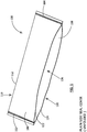
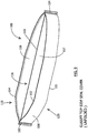
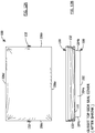
- FIG. 1 illustrates cover 100, according to a first example.
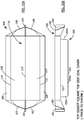
- FIG. 2 illustrates a section view of cover 100, according to the first example.
- cover 100 can be formed from a single sheet of polymeric material.
- the sheet of material can be folded in half and sealed on either side to form a closed top end, bottom opening, and two sealed sides.
- Any of the seals disclosed herein can be formed by heat or thermo-sealing, impulse-sealing, sonic-sealing, RF-sealing, or any other type of sealing.
- Other suitable techniques can be used to seal cover 100, such as bonding, stitching, adhesion, etc.
- Cover 100 can include top end 110 having first top edge 112.
- cover 100 can include first side seal 102 and second side seal 104. Forming cover 100 in this manner can create bottom end 120, having first bottom edge 122, second bottom edge 124, and opening 126.
- First lateral wall 106 can be bounded by first side seal 102, second side seal 104, first top edge 112, and first bottom edge 122.
- Second lateral wall 108 can be bounded by first side seal 102, second side seal 104, first top edge 112, and second bottom edge 124.
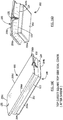
- FIGS. 3A-3D illustrate the first example of cover 100 placed over pan 200, prior to heat-shrinking.
- Pan 200 can be made of any suitable material, for example, but not limited to, stainless steel, copper, aluminum, glass, ceramic, plastic, etc.
- pan 200 can include bottom panel 202 and side walls 204a, 204b, 204c, and 204d, which can extend upwardly from bottom panel 202.
- Each side wall 204a-d can terminate in a respective top edge 206a, 206b, 206c, and 206d.
- Top edges 206a-d can form pan opening 208.
- a flange can extend from top edges 206a-d. It is understood that pan 200 can be many other shapes and sizes.
- cover 100 can be placed over pan 200 such that first top edge 112 of cover 100 is located approximately at a midpoint of top edges 206b and 206c of pan 200.
- first top edge 112 can be off-center.
- first lateral wall 106 can extend outside side wall 204a and second lateral wall 108 can extend outside side wall 204d.
- cover 100 Prior to heat-shrinking, cover 100 can form a triangular shape at opposite ends of pan 200, as it is fitted over pan 200. As shown, for example, in FIG. 3B , the excess material of cover 100 can extend beyond side walls 204b and 204c. It is understood that cover 100 can be placed over pan 200 in any other configuration or direction.
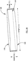
- FIGS. 4A-4D illustrate the first example of cover 100 after heat-shrinking cover 100 about pan 200.
- the first example of cover 100 can sometimes have poor sealing areas 130 between cover 100 and pan 200. This can result in spillage, leakage, or spoiling of food contained in pan 200.
- heat-shrinking cover 100 can cause first bottom edge 122 and second bottom edge 124 to at least partially seal around side walls 204a-d of pan 200.
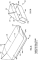
- FIG. 5 illustrates cover 100, according to a second example.
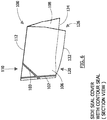
- FIG. 6 illustrates a section view of cover 100, according to the second example.
- the second example can include first angled seal 103 and second angled seal 105.
- First angled seal 103 and second angled seal 105 can be formed by any of the methods disclosed herein.
- first angled seal 103 can extend from first side seal 102 to first top edge 112.
- second angled seal 105 can extend from second side seal 104 to first top edge 112.
- First angled seal 103 and second angled seal 105 can seal first lateral wall 106 and second lateral wall 108 together along the respective seal.
- First angled seal 103 can have a first end located anywhere along first side seal 102 and a second end located anywhere along first top edge 112.
- Second angled seal 105 can have a first end located anywhere along second side seal 104 and a second end located anywhere along first top edge 112.
- First angled seal 103 and second angled seal 105 can create a more form-fitting shape for cover 100 when placed on pan 200, in comparison to the first example.
- FIGS. 7A-7D illustrate the second example of cover 100 placed over pan 200, prior to heat-shrinking.
- the excess portion of cover 100 extending beyond side walls 204b and 204c of pan 200 can be more tapered, in comparison to the first example.
- FIGS. 8A-8D illustrate the second example of cover 100 after heat-shrinking.
- areas of excess material 132 can form at either end of cover 100 as it shrinks around pan 200.
- first bottom edge 122 and second bottom edge 124 can form a seal around side walls 204a-d of pan 200.
- the second example can form a tighter seal between cover 100 and pan 200 in comparison to the first example.
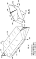
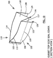
- FIG. 9 illustrates cover 100, according to a third example.
- FIG. 10 illustrates a section view of cover 100, according to the third example.
- cover 100 can include top end 110, first side seal 102, second side seal 104, and bottom end 120.
- top end 110 can include first top edge 112 and second top edge 114.
- bottom end 120 can include first bottom edge 122, second bottom edge 124, and opening 126.
- cover 100 includes gusset 116.
- Gusset 116 can extend between first top edge 112 and second top edge 114.
- gusset 116 can have fold line 119.
- fold line 119 can be located approximately half-way between first top edge 112 and second top edge 114.
- Gusset 116 can include first top panel 117 and second top panel 118.
- First top panel 117 can be bounded between first top edge 112 and fold line 119.
- Second top panel 118 can be bounded between second top edge 114 and fold line 119.
- gusset 116 can include more than one fold.
- gusset 116 can have a W-shape, where each portion is the same length or different lengths.
- gusset 116 can form a V-shape between first lateral wall 106 and second lateral wall 108.
- first top panel 117 can be approximately equal in size to first lateral wall 106.
- Second top panel 118 can be approximately equal in size to second lateral wall 108.
- First top panel 117 and second top panel 118 can also be larger or smaller in size than first lateral wall 106 and second lateral wall 108, respectively.
- FIGS. 11A-11D illustrate the third example of cover 100 placed over pan 200, prior to heat-shrinking.
- fold line 119 of gusset 116 can be located approximately along a midpoint of side walls 204b and 204c of pan 200.
- fold line 119 can be located off-center.
- first top panel 117 and second top panel 118 of gusset 116 can extend only part way between a center of pan 200 and side walls 204a and 204d.
- first top panel 117 and/or second top panel 118 can extend to or beyond side walls 204a and 204d of pan 200.
- first lateral wall 106 and second lateral wall 108 can extend over top edges 206a and 206d of pan 200, and down along side walls 204a and 204d of pan 200.
- FIGS. 12A-12D illustrate the third example of cover 100, after heat-shrinking.
- some excess material 132 can form along side walls 204b and 204c.
- the third example of cover 100 can provide a tighter seal between cover 100 and pan 200 in comparison to the first and second examples of cover 100.
- a tight seal can be formed between first bottom edge 122 and side walls 204a-c, and between second bottom edge 124 and side walls 204b-d.
- FIG. 13 illustrates cover 100, according to a fourth example.
- FIG. 14 illustrates a section view of the cover 100, according to the fourth example.
- the fourth example can include first angled seal 103.
- Second angled seal 105 can be located at an opposite end of cover 100, for example, as shown in FIG. 15B .
- First angled seal 103 can seal first lateral wall 106 to first top panel 117 of gusset 116 from first side seal 102 to first top edge 112.
- Second angled seal 105 can seal first lateral wall 106 and first top panel 117 from second side seal 104 to first top edge 112.
- FIG. 15B illustrates cover 100, according to a fourth example.
- third angled seal 107 can seal second lateral wall 108 and second top panel 118 from first side seal 102 to second top edge 114.
- Fourth angled seal 109 can seal second lateral wall 108 and second top panel 118 from second side seal 104 to second top edge 114.
- FIGS. 15A-15D illustrate the fourth example of cover 100 placed over pan 200, prior to heat-shrinking.
- the design of the fourth example can create pockets 134 in cover 100 when placed over pan 200.
- FIGS. 16A-16D illustrate the fourth example of cover 100, after heat-shrinking.
- some excess material 132 can accumulate at side walls 204b and 204c after heat-shrinking.
- the fourth example of cover 100 can provide a better seal between cover 100 and pan 200 than the first and second examples of cover 100, and at least as good as the third example of cover 100.
- a tight seal can be formed between first bottom edge 122 and side walls 204a-c, and between second bottom edge 124 and side walls 204b-d.
- cover 100 has a shallow bag-like structure and is formed from a thin film.
- the cover is pre-formed into a shape to match the shape of the open end of a pan to be covered.
- Cover 300 can be formed, for example, by thermoforming from a material having the properties described above but from a thicker film.
- the film can be approximately five to twenty mils (.005" to .020") thick.
- cover 300 includes a planar portion 302 and an edge portion 304.
- FIG. 20 is a sectional view showing cover 300 fit to pan 200.
- Edge portion 304 is configured to mate with edge 206 and a flange 205 of pan 200.
- edge portion 304 has a "U" shaped cross sectional shape to mate with flange 205.
- heat may be applied to cover 300 (e.g., by placing the pan and cover combination into a heated oven for cooking) to shrink cover 300 so that it snugly fits and seals the top opening of pan 200.
- cover 300 can have dimensions of 546.1 mm (21.5") long by 342.9 mm (13.5") wide with an edge portion having a depth or thickness of 6.35 mm (0.25") to wrap around flange 205.
- cover 300 can be thermoformed from MQ520 film in a thickness of 5 mils (0.005").
- Certain embodiments of the food pan covers include features that facilitate removal of the cover from the pan after heat-shrinking. Rather than, for example, cutting the cover off with scissors or a knife, certain embodiments include flaps and/or tabs that can simply be pulled in order to remove the cover from the pan.
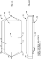
- FIG. 21 illustrates cover 400, according to one such embodiment.
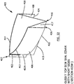
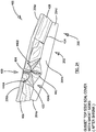
- FIG. 22 illustrates a section view of cover 400, according to this embodiment.
- FIGS. 23A and 23B illustrate cover 400 placed over pan 200, prior to heat-shrinking.
- Pan 200 can be a pan such as the one described above with respect to FIG. 17 .
- cover 400 includes first end 407, second end 409, first side panel 406, and second side panel 408 (not visible in FIG. 21 ).
- First side panel 406 has first top edge 412 and first bottom edge 422.
- Second side panel 408 has second top edge 414 and second bottom edge 424 (not visible in FIG. 21 ).
- Cover 400 includes gusset 416 between first side panel 406 and second side panel 408.
- Gusset 416 includes third bottom edge 419.
- Gusset 416 has first gusset panel 417 and second gusset panel 418.
- First gusset panel 417 is delineated by first end 407, second end 409, first top edge 412, and third bottom edge 419.
- Second gusset panel 418 is delineated by first end 407, second end 409, second top edge 414, and third bottom edge 419.
- a similar space can be created between second gusset panel 418 and second side panel 408.
- the width (W G ) of first gusset panel 417 is greater than a width (W SP ) of first side panel 406.
- a width (W G ) of second gusset panel 418 is greater than a width (W SP ) of second side panel 408.
- the width (W G ) of first gusset panel 417 and second gusset panel 418 can be the same or different.
- the width (W SP ) of first side panel 406 and second side panel 408 can be the same or different.
- Cover 400 has first side seal 402 extending along a portion of first end 407.
- First side seal 402 seals together a portion of each of first side panel 406, second side panel 408, first gusset panel 417, and second gusset panel 418.
- first side seal 402 can begin at or near first top edge 412 and second top edge 414.
- First side seal 402 can extend toward first bottom edge 422 and second bottom edge 424.
- first side seal 402 can begin on first end 407 at a point below first top edge 412 and second top edge 414 and extend only part way toward bottom edges 422, 424. Such a shortened side seal will create a first unsealed portion 402A on first end 407.
- Cover 400 has second side seal 404 extending along a portion of second end 409.
- Second side seal 404 seals together a portion of each of first side panel 406, second side panel 408, first gusset panel 417, and the second gusset panel 418.
- second side seal 404 can begin at or near first top edge 412 and second top edge 414.
- Second side seal 404 can extend toward first bottom edge 422 and second bottom edge 424.
- second side seal 404 can begin on second end 409 at a point below top edge 412 and second top edge 414 and extend only part way toward edges 422, 424. Such a shortened side seal will create a second unsealed portion 404A on second end 409.
- cover 400 has a length (L C ), side panels 406 and 408 (not visible in FIG. 21 , see FIG. 22 ) have a width (W SP ), and gusset panels 417, 418 have a width (W G ).
- Table 3 provides several examples of pan cover dimensions for pan covers that can be used with several standard Gastronorm pan types. Other dimensions are also contemplated.
- side seals 402, 404 of cover 400 are shorter than the width (W SP ) of side panels 406, 408.
- side seals 402, 404 are approximately 3 inches (76.2 mm) in length. Other lengths for side seals 402, 404 are contemplated.
- cover 400 can be placed over pan 200.
- third bottom edge 419 of gusset 416 can be located approximately along a midpoint of side walls 204b and 204c of pan 200.
- third bottom edge 419 can be located off-center.
- First gusset panel 417 and/or second gusset panel 418 of gusset 116 can extend only part way between a center of pan 200 and side walls 204a and 204d, or first gusset panel 417 and/or second gusset panel 418 can extend to or beyond side walls 204a and 204d of pan 200.
- first side panel 406 and second side panel 408 extend over top edges 206a and 206d of pan 200, and down along side walls 204a and 204d of pan 200.
- second unsealed portion 404A of second end 409 can form a first flap 440A and a second flap 440B.
- Second unsealed portion 404A can also form a tab 442.
- first unsealed portion 402A of first end 407 (not shown) can also have a first flap, a second flap, and a tab. These flaps and tabs can facilitate removing cover 400 off of the pan by pulling the flaps or tabs to tear the cover.
- first side seal 402 and/or second side seal 404 can extend along more than half the width (W SP ) of the side panels. In other embodiments, first side seal 402 and/or second side seal 404 can extend along less than half the width (W SP ) of the side panels. In certain embodiments, first side seal 402 and/or second side seal 404 can extend along approximately half the width (W SP ) of the side panels.
- first side seal 402 and second side seal 404 can also be compared relative to the lengths first gusset panel 417 and second gusset panel 418.
- first side seal 402 and/or second side seal 404 can extend along more than half the width (W G ) of the gusset panels. In other embodiments, first side seal 402 and/or second side seal 404 can extend along less than half the width (W G ) of the gusset panels. In certain embodiments, first side seal 402 and/or second side seal 404 can extend along approximately half the width (W G ) of the gusset panels. Having larger first and second unsealed portions 402A/404A can increase the size of flaps 440A/440B and tab 442.
- cover 400 is formed from a heat-shrinkable polymeric material.
- the material can be substantially clear (i.e., substantially transparent).
- cover 400 can be a monolayer film having a thickness of about one mil. Multi-layer films and various thicknesses for cover 400 are also contemplated.
- cover 400 can withstand a temperature of at least about 204 degrees Celsius (400 degrees Fahrenheit) for at least about two hours.
- a food containment system includes a pan and a pan cover.
- the pan cover has the features of claim 1 and the gusset can be formed from a single layer of heat-shrinkable polymeric material capable of withstanding a temperature of at least about 204 degrees Celsius (400 degrees Fahrenheit).
- the pan is a Gastronorm pan.
- the Gastronorm pan can be a shallow, medium, or deep third pan.
- the food pan cover can have a length (L C ) between 482.6 and 533.4 mm (19 and 21 inches), and the width (W G ) of the first and second gusset panels can be between 127 and 177.8 mm (5 and 7 inches).
- the width (W SP ) of the first and second side panels can be between 101.6 and 127 mm (4 and 5 inches).
- the food containment system can be used by placing the pan cover over the pan, as shown, for example, in the food containment systems in FIGS. 3A-3D , 7A-7D , 11A-11D , 15A-15D , 20 , and 23A-23B .
- the pan cover can be heated (e.g., using a hot air gun such as a handheld hairdryer, using an infrared lamp or by placing the pan/cover system in an oven), causing the pan cover to shrink and seal about the pan, as shown, for example, in the food containment systems in FIGS. 4A-4D , 8A-8D , 12A-12D , 16A-16D , and 24 .
- Methods of sealing a food pan are also contemplated and disclosed herein. This method includes the steps of: placing food in a food pan; placing a cover over the pan, and heating at least the cover causing it to shrink-fit to the pan. Heating the cover can be accomplished by exposing the cover to cooking temperatures (e.g., at least 149 degrees Celsius (300 degrees Fahrenheit)), as opposed to “heat sealing” or “welding” techniques known in the art. Sealing the pan cover about the pan can prevent spillage, leakage, or spoilage of the contents inside the pan.
- cooking temperatures e.g., at least 149 degrees Celsius (300 degrees Fahrenheit)
- the pan cover includes a gusset.
- the method of sealing a food pan can include opening the bag-like cover to expand the gusset. Expanding the gusset increases a distance between a first lateral wall and second lateral wall (i.e., formed by the first and second side panels and optionally a portion of the gusset walls) of the pan cover. Increasing the distance between the first and second lateral walls (side panels) improves the fit of the pan cover to the pan.
- the method can include heating the food, for example, at a temperature of at least about 149 degrees Celsius (300 degrees Fahrenheit).
- the food pan cover can be removed by applying a force to (e.g., pulling) at least one of a first flap, a second flap, a third flap, a fourth flap, a first tab, or a second tab of the cover.
Landscapes
- Engineering & Computer Science (AREA)
- Food Science & Technology (AREA)
- Life Sciences & Earth Sciences (AREA)
- Mechanical Engineering (AREA)
- Cookers (AREA)
- Packages (AREA)
Description
- The present disclosure relates to covers for food service pans and food containment systems. More specifically, the present disclosure relates to ovenable, heat-shrinkable covers for food service pans and food containment systems.
- Large food service pans are used for cooking, serving, and storing food in commercial food service establishments. These pans can be used in food servers, such as steam tables, buffet tables, chill tables, salad bars, chafing dishes, and the like. These pans can be used, for example, to cook and heat food, store food, and/or as transfer pans to carry large portions of food to and from a serving area. Conventional metal (e.g., stainless steel) food service pans are available in a variety of shapes, including rectangular and circular shapes. Such pans typically have a flange extending around a peripheral edge of the open pan top. The flange supports the pan in a steam or buffet table, provides a steam seal around a steam table, and offers a convenient lifting and carrying point. When used in a steam table, buffet table, salad bar, or the like, the pan body (e.g., the food receptacle portion) and flange are typically dimensioned so that the receptacle is received into an opening in the table or bar and supported by its flange resting upon the edges of the table or bar opening.
- With the primary objective of moisture retention, various sheets, films, and covers have been used to cover such pans during food preparation, cooking, and storage. For example, paper sheets of cellulosic fibers have been used, as well as various plastic films. Thin metal foils, so-called tin foils, which are in reality thin sheets of aluminum, have also been used extensively for cooking, heating, and storing foods.
- Difficulties with such conventional covers include tearing, breaking, leaking, and the inability to stack the pans in a refrigerator, walk-in box, or in transport. Also, many covers are not ovenable (i.e., the cover cannot be subjected to cooking temperatures without melting, cracking or contaminating food). For example, metal foils are notoriously easy to puncture and tear (e.g., by serving utensils). Further, metal foils are opaque and do not allow easy viewing of the contents of the container. They also cannot be heated in a microwave oven. In addition, sheets of metallic materials are relatively expensive as compared to other materials.
- While paper sheets are useful for some culinary purposes, they are not ideal for pan covering because they are easily torn, are moisture and air permeable, and do not seal well around pans. In addition, paper sheets are typically not suitable for high temperature cooking applications.
- Thermoplastic films, such as polyethylene films, offer greater durability. However, a problem with conventional films is that they typically do not grip or cling well to a pan edge, thereby allowing spillage, leakage, or spoilage. Furthermore, many thermoplastic films are not ovenable and, therefore, cannot be used when reheating or cooking food in the pan. Some films even emit dangerous chemicals when heated.
- In an attempt to overcome the shortcomings of conventional coverings, industry practice has been to use multiple coverings to cover a single pan. For example, a layer of plastic film (for puncture and tear resistance) is wrapped over the pan, followed by a layer of foil to hold the plastic film in place. This practice increases the time and expense for covering a pan. And still, the negative features of the plastic film and the foil are not overcome.
- Still another disadvantage of these conventional pan covering methods is frequent worker injury. Covering a pan typically involves pulling a plastic sheet or metal foil from a roll and forcing the sheet or foil against a serrated metal cutter edge to remove a desired length of the plastic sheet or foil. When moving quickly, as workers in a commercial kitchen are often required to do, a worker can cut his or her finger or hand on the cutter edge. Such a cut is an undesirable incident in a food service environment.
- Further, conventional pan covering methods do not provide a quick and simple way to remove the pan covering(s) from the pan. Often, multiple layers must be unwrapped, without an easy gripping point to remove the cover.
- There is a need, therefore, for an improved food service pan cover. In particular, there is a need for a simple, flexible, replaceable, disposable, transparent, and durable pan cover having non-stick and high temperature attributes, that conforms to the shape, size, and contour of the pan or food receptacle. Further, there is a need for pan covers that provide moisture retention, reduce leakage, and allow multiple pans to be stacked on top of each other.
-
US2006/191985 discloses an erectable and collapsible container including a plurality of side walls joined along a plurality of wall hinges providing articulation between the side walls. A bottom wall is attached to the side walls at edge hinges providing articulation between the side walls and the bottom wall. At least one flexible gusset portion is provided extending between one or more of the side walls and the bottom wall, and the gusset portion is movable with the bottom wall in response to movement of the side walls and the bottom wall between collapsed and erected configurations. Structure is provided for maintaining the side walls in the erected configuration such that the side walls define a generally rigid or semi-rigid structure. A pair of opposed flexible panels extend from the side walls and define a bag-like upper portion extending from the support structure and forming a sealable opening for the container. - The present disclosure is directed to covers for food service pans, food containment systems, and methods of covering and sealing food pans. In certain examples, the food pan cover can be a bag-like structure having a closed top, an open bottom, and two sealed sides. In other embodiments, the cover is pre-shaped by, for example, thermoforming to fit a pan.
- In certain embodiments, the food pan cover can be formed from a single layer of polymeric material that is heat shrinkable. The polymeric material is ovenable and safe for contact with food at cooking temperatures. Preferably, the cover can withstand a temperature of at least about 204 degrees Celsius (400 degrees Fahrenheit) for a minimum of about two hours, preferably about four hours, and most preferably at least about six hours. Preferably, the cover is at least partially transparent, such that the contents of the pan can be viewed through the cover.
- Various embodiments of the cover are disclosed. Certain embodiments provide manufacturing advantages (e.g., lower cost) while others provide better sealing to a particular pan shape and size.
- In certain examples, the food pan cover has a closed top end having a first top edge and an open bottom end having a first bottom edge and a second bottom edge. The food pan cover also has a first side seal extending from the top end to the bottom end and a second side seal extending from the top end to the bottom end. A first lateral wall is formed by the first top edge, first bottom edge, first side seal, and second side seal. A second lateral wall is formed by the first top edge, second bottom edge, first side seal, and second side seal.
- In certain examples, the first lateral wall and the second lateral wall meet at the first top edge. The food pan cover also includes a first angled seal extending from the first side seal to the first top edge and a second angled seal extending from the second side seal to the first top edge.
- In certain examples, the top end can include a second top edge. The first lateral wall is formed by the first top edge, first bottom edge, first side seal, and second side seal. The second lateral wall is formed by the second top edge, second bottom edge, first side seal, and second side seal.
- In another example, the food pan cover can include a gusset. The gusset is formed between the first top edge and the second top edge. The gusset includes a fold line, a first top panel bounded by the first top edge and the fold line, and a second top panel bounded by the second top edge and the fold line. In certain embodiments, each of the first and second lateral walls include a first angled seal extending from the first side seal to the respective top edge and a second angled seal extending from the second side seal to the respective top edge.
- In an example, the food pan cover can have a closed top end having a first top edge and a second top edge and an open bottom end having a first bottom edge and a second bottom edge. The food pan cover has a first side seal extending from the top end to the bottom end and a second side seal extending from the top end to the bottom end. A first lateral wall is formed by the first top edge, first bottom edge, first side seal, and second side seal. A second lateral wall is formed by the second top edge, second bottom edge, first side seal, and second side seal. A gusset is formed between the first top edge and the second top edge.
- In certain examples, the gusset includes a fold line, a first top panel bounded by the first top edge and the fold line, and a second top panel bounded by the second top edge and the fold line. The gusset can expand to increase a distance between the first lateral wall and the second lateral wall. In certain embodiments, the first top panel is approximately equal in size to the first lateral wall, and the second top panel is approximately equal in size to the second lateral wall.
- According to the invention, a food pan cover formed from a heat-shrinkable material has a first end, a second end, a first side panel having a first top edge and a first bottom edge, and a second side panel having a second top edge and a second bottom edge. A gusset is formed between the first side panel and the second side panel. The gusset has a third bottom edge, a first gusset panel delineated by the first end, the second end, the first top edge, and the third bottom edge, and a second gusset panel delineated by the first end, the second end, the second top edge, and the third bottom edge. A width of the first gusset panel is greater than a width of the first side panel, and a width of the second gusset panel is greater than a width of the second side panel. According to the invention, the food pan cover can be used with a Gastronorm pan to form a food containment system.
- According to the invention, the food pan cover has a first side seal extending along a portion of the first end, sealing together a portion of each of the first side panel, the second side panel, the first gusset panel, and the second gusset panel. The food pan cover also has a second side seal extending along a portion of the second end, sealing together a portion of each of the first side panel, the second side panel, the first gusset panel, and the second gusset panel.
- In certain embodiments, the first end can have a sealed portion and an unsealed portion. After heat-shrinking the food pan cover over the opening of a pan, the unsealed portion of the first end can form a first flap and a second flap. The unsealed portion of the first end can also have a first tab. The second end can also have a sealed portion and an unsealed portion. After heat-shrinking the food pan cover over the opening of a pan, the unsealed portion of the second end can form a third flap and a fourth flap. The unsealed portion of the second end can also have a second tab.
- In certain embodiments, at least one of the first or second side seal extends along more than half the width of the first or second side panel. In other embodiments, at least one of the first or second side seal extends along less than half the width of the first or second side panel. In certain embodiments, at least one of the first or second side seal extends along approximately half the width of the first or second side panel.
- In certain embodiments, at least one of the first or second side seal extends along more than half the width of the first or second gusset panel. In other embodiments, at least one of the first or second side seal extends along less than half the width of the first or second gusset panel. In certain embodiments, at least one of the first or second side seal extends along approximately half the width of the first or second gusset panel.
- In certain embodiments, the width of the first side panel is approximately equal to the width of the second side panel. The width of the first gusset panel can be approximately equal to the width of the second gusset panel.
- The heat-shrinkable material can be a polymeric material. In certain embodiments, the heat-shrinkable material can be a mono-layer film having a thickness of about one mil. In certain embodiments, the heat-shrinkable material is capable of withstanding a temperature of at least about 204 degrees Celsius (400 degrees Fahrenheit) for at least about two hours.
- According to the invention, the food pan cover is sized to fit about a Gastronorm pan. The pan can have a bottom surface and one or more side walls extending upwardly from the bottom surface, each side wall having a top edge defining a top opening of the pan. In certain embodiments, at least a portion of the first side panel of the food pan cover can be located outside a first side wall of the pan and at least a portion of the second side panel can be located outside a second side wall of the pan, when the pan cover is covering the pan. The pan cover can be configured to shrink when heat is applied to the pan cover so that the pan cover engages a peripheral lip of the pan at the top opening to cover and seal the top opening.
- In certain embodiments, the Gastronorm pan can be a shallow, medium, or deep third pan. The food pan cover can have a length between 482.6 and 533.4 mm (19 and 21 inches), and the width of the first and second gusset panels can be between 127 and 177.8 mm (5 and 7 inches). In certain embodiments, the width of the first and second side panels can be between 101.6 and 127 mm (4 and 5 inches).
- In certain embodiments, the polymeric material of the food pan cover can be substantially clear (i.e., transparent or translucent) to allow the contents of a pan to be viewed through the cover. Labeling information (e.g., contents, date, etc.) can be written on the cover, for example, with a marker or felt-tipped pen.
- In certain embodiments, the food pan cover can include a first angled seal extending from the first side seal to the first top edge and a second angled seal extending from the second side seal to the first top edge. The food pan cover also includes a third angled seal extending from the first side seal to the second top edge and a fourth angled seal extending from the second side seal to the second top edge.
- In certain embodiments, the food pan cover can be tinted different colors using pigments, dyes, etc. The coloring can be for aesthetic purposes or to provide a color coding system to indicate, for example, the type of food contained within the pan. The cover can be translucent even with the coloring, so that the contents of the pan can still be viewed.
- In certain embodiments, various information can be printed on the covers. For example, the name, address, or website of a kitchen or restaurant can be printed on the covers. Expiration dates, food preparation instructions, bar codes, etc. can also be printed on the covers. In addition, or as an alternative, labels can be applied to the covers with similar information.
- In certain embodiments, the covers can include perforations. The perforations can be small pin holes that allow steam to escape from the pan during cooking, which can help control the quality of the food being cooked. For example, when cooking meat, allowing steam to escape can help the meat properly brown.
- In certain embodiments, tear locations can be added to the covers. For example, one or more tear notches can be located along the sides, edges, or seals of the cover. Tear notches can make it easier to remove the cover from the pan after cooking, without requiring the use of a knife, scissors, etc.
- In another embodiment, the food pan cover is pre-formed into a shape to match the shape of the open end of a pan to be covered.
- Food containment systems according to the invention comprise the features of claim 1. The food containment system includes a Gastronorm pan and a food pan cover configured to fit about the Gastronorm pan. The food pan cover can be formed from a heat-shrinkable polymeric material capable of withstanding a temperature of at least about 204 degrees Celsius (400 degrees Fahrenheit) for at least about two hours. The food pan cover has a first end, a second end, a first side panel having a first top edge and a first bottom edge, and a second side panel having a second top edge and a second bottom edge. A gusset is formed between the first side panel and the second side panel. The gusset has a third bottom edge, a first gusset panel delineated by the first end, the second end, the first top edge, and the third bottom edge, and a second gusset panel delineated by the first end, the second end, the second top edge, and the third bottom edge. A width of the first gusset panel is greater than a width of the first side panel, and a width of the second gusset panel is greater than a width of the second side panel.
- In the food containment systems according to the invention, the food pan cover has a first side seal extending along a portion of the first end, sealing together a portion of each of the first side panel, the second side panel, the first gusset panel, and the second gusset panel. The food pan cover also has a second side seal extending along a portion of the second end, sealing together a portion of each of the first side panel, the second side panel, the first gusset panel, and the second gusset panel. The first and second ends can each have a sealed portion and an unsealed portion. After heat-shrinking the food pan cover over the opening of a pan, the unsealed portion of the first end forms a first flap, a second flap, and a first tab, and the unsealed portion of the second end forms a third flap, a fourth flap, and a second tab.
- Methods of sealing a food pan are also contemplated and disclosed herein. A food pan, for example, any of the food pans described herein, can be covered with a pan cover, for example, any of the pan covers disclosed herein. The method can also include heating the food, for example, at a temperature of at least about 149 degrees Celsius (300 degrees Fahrenheit). In certain embodiments, the food pan cover can be removed by applying a force to (e.g., pulling on) at least one of the first flap, second flap, third flap, fourth flap, first tab, or second tab of the cover.
- The accompanying figures, which are incorporated herein, form part of the specification and some of them illustrate embodiments of the present invention. Together with the description, the figures further serve to explain the principles of and to enable a person skilled in the relevant arts to make and use the disclosed embodiments. These figures are intended to be illustrative, not limiting. Although the disclosure is generally described in the context of these embodiments, it should be understood that it is not intended to limit the scope of the disclosure to these particular embodiments. In the drawings, like reference numbers indicate identical or functionally similar elements.
-
FIG. 1 illustrates a food pan cover, according to an example that does not fall under the scope of the claims. -
FIG. 2 illustrates a section view of a food pan cover according to an example that does not fall under the scope of the claims. -
FIG. 3A illustrates a top view of a food pan cover on a food pan prior to heat-shrinking, according to an example that does not fall under the scope of the claims. -
FIG. 3B illustrates a side view of a food pan cover on a food pan prior to heat-shrinking, according to an example that does not fall under the scope of the claims. -
FIGS. 3C and 3D illustrate perspective views of a food pan cover on a food pan prior to heat-shrinking, according to an example that does not fall under the scope of the claims. -
FIG. 4A illustrates a top view of food pan cover on a food pan after heat-shrinking, according to an example that does not fall under the scope of the claims. -
FIG. 4B illustrates a side view of a food pan cover on a food pan after heat-shrinking, according to an example that does not fall under the scope of the claims. -
FIGS. 4C and 4D illustrate perspective views of a food pan cover on a food pan after heat-shrinking, according to an example that does not fall under the scope of the claims. -
FIG. 5 illustrates a food pan cover, according to an example that does not fall under the scope of the claims. -
FIG. 6 illustrates a section view of a food pan cover, according to an example that does not fall under the scope of the claims. -
FIG. 7A illustrates a top view of a food pan cover on a food pan prior to heat-shrinking, according to an example that does not fall under the scope of the claims. -
FIG. 7B illustrates a side view of a food pan cover on a food pan prior to heat-shrinking, according to an example that does not fall under the scope of the claims. -
FIGS. 7C and 7D illustrate perspective views of a food pan cover on a food pan prior to heat-shrinking, according to an example that does not fall under the scope of the claims. -
FIG. 8A illustrates a top view of food pan cover on a food pan after heat-shrinking, according to an example that does not fall under the scope of the claims. -
FIG. 8B illustrates a side view of a food pan cover on a food pan after heat-shrinking, according to an example that does not fall under the scope of the claims. -
FIGS. 8C and 8D illustrate perspective views of a food pan cover on a food pan after heat-shrinking, according to an example that does not fall under the scope of the claims. -
FIG. 9 illustrates a food pan cover, according to an example that does not fall under the scope of the claims. -
FIG. 10 illustrates a section view of a food pan cover, according to an example that does not fall under the scope of the claims. -
FIG. 11A illustrates a top view of a food pan cover on a food pan prior to heat-shrinking, according to an example that does not fall under the scope of the claims. -
FIG. 11B illustrates a side view of a food pan cover on a food pan prior to heat-shrinking, according to an example that does not fall under the scope of the claims. -
FIGS. 11C and 11D illustrate perspective views of a food pan cover on a food pan prior to heat-shrinking, according to an an example that does not fall under the scope of the claims. -
FIG. 12A illustrates a top view of food pan cover on a food pan after heat-shrinking, according to an example that does not fall under the scope of the claims. -
FIG. 12B illustrates a side view of a food pan cover on a food pan after heat-shrinking, according to an example that does not fall under the scope of the claims. -
FIGS. 12C and 12D illustrate perspective views of a food pan cover on a food pan after heat-shrinking, according to an example that does not fall under the scope of the claims. -
FIG. 13 illustrates a food pan cover, according to an example that does not fall under the scope of the claims. -
FIG. 14 illustrates a section view of a food pan cover, according to an example that does not fall under the scope of the claims. -
FIG. 15A illustrates a top view of a food pan cover on a food pan prior to heat-shrinking, according to an example that does not fall under the scope of the claims. -
FIG. 15B illustrates a side view of a food pan cover on a food pan prior to heat-shrinking, according to an example that does not fall under the scope of the claims. -
FIGS. 15C and 15D illustrate perspective views of a food pan cover on a food pan prior to heat-shrinking, according to an example that does not fall under the scope of the claims. -
FIG. 16A illustrates a top view of food pan cover on a food pan after heat-shrinking, according to an example that does not fall under the scope of the claims. -
FIG. 16B illustrates a side view of a food pan cover on a food pan after heat-shrinking, according to an example that does not fall under the scope of the claims. -
FIGS. 16C and 16D illustrate perspective views of a food pan cover on a food pan after heat-shrinking, according to an example that does not fall under the scope of the claims. -
FIG. 17 illustrates a pan, according to an example that does not fall under the scope of the claims. -
FIG. 18 illustrates a food pan cover, according to an example that does not fall under the scope of the claims. -
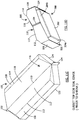
FIG. 19 illustrates a pre-formed cover in accordance with yet another example that does not fall under the scope of the claims. -
FIG. 20 is a sectional view showing the cover ofFIG. 19 to a pan. -
FIG. 21 illustrates a food pan cover, according to an embodiment disclosed herein. -
FIG. 22 illustrates a section view of a food pan cover, according to an embodiment disclosed herein. -
FIG. 23A illustrates a top view of a food pan cover on a food pan prior to heat-shrinking, according to an embodiment disclosed herein. -
FIG. 23B illustrates a side view of a pan cover on a food pan prior to heat-shrinking, according to an embodiment disclosed herein. -
FIG. 24 illustrates a perspective view of a food pan cover on a food pan after heat-shrinking, according to an embodiment disclosed herein. - Embodiments of the present disclosure will now be described in detail with reference to embodiments thereof as illustrated in the accompanying drawings, in which like reference numerals are used to indicate identical or functionally similar elements. References to "one embodiment", "an embodiment", "some embodiments", "in certain embodiments", etc., indicate that the embodiment described may include a particular feature, structure, or characteristic. When a particular feature, structure, or characteristic is described in connection with an embodiment, it is submitted that it is within the knowledge of one skilled in the art to affect such feature, structure, or characteristic in connection with other embodiments whether or not explicitly described, within the framework of the appended claims.
- The following examples are illustrative, but not limiting, of the present disclosure. Other suitable modifications and adaptations of the variety of conditions and parameters normally encountered in the field, and which would be apparent to those skilled in the art, are within the scope of the disclosure and the appended claims.
- The covers disclosed herein can be used for covering and sealing food pans such as Gastronorm pans (see, e.g., the European Committee for Standardization standard sizes for containers used in the catering industry as specified in the EN 631 standard). The covers can also be used in conjunction with other food containment systems, or any other type of containment system (e.g., product storage).
- Table 1 shows examples of standard Gastronorm pan sizes used in commercial and industrial kitchens.
TABLE 1 Standard Size Pans. Pan Description Pan Size (L × W) Pan Depth (H) Half Pan-Shallow 12.8" × 10.4" 2.5" Half Pan-Medium & Deep 12.8" × 10.4" 4" & 6" Third & Quarter Pan-Medium & Deep 12.8" × 6.9" 4" & 6" Third & Quarter Pan-Shallow 12.8" × 6.9" 2.5" Sixth Pan 6.4" × 6.9" 6" Hotel Pan-Shallow & Medium 12.8" × 20.8" 2.5" & 6" Hotel Pan-Deep 12.8" × 20.8" 6" 2 Quart Round 8.2" 4 Quart Round 8.2" 6 & 7 Quart Round 8.2" 9 & 11 Quart Round 8.2" Bun Sheet Pan 18.5" × 26.5" n/a G.I. Roasting Pan 20" × 17" 6.5" Large Roasting Pan 25.5" × 17.5" 4" - 12.8" is 325.12mm; 10.4" is 264.16mm; 2.5" is 63.5mm; 4" is 101.6mm; 6" is 152.4mm; 6.9" is 175.26mm; 6.4" is 162.56mm; 20.8" is 528.32mm; 8.2" is 208.28mm; 18.5" is 469.9mm; 26.5" is 673.1mm; 20" is 508mm; 17" is 431.8mm; 6.5" is 165.1mm; 25.5" is 647.7mm; 17.5" is 444.5mm.
- While the embodiments of the invention find particular application and advantage when used with a Gastronorm cooking pan, the covers and containment systems disclosed herein are not so limited. For example, the covers disclosed herein can be used with pots, trays, roasting pans, baking dishes, containers, kettles, bowls, slow cookers, crock pots, electric roasters, etc., in a variety of shapes and sizes. Preferably, covers can be manufactured for standard cooking, transportation, and storage devices used in the food service industry. Alternatively, custom shapes and sizes for covers can be manufactured and used. It is understood that the covers disclosed herein can also be utilized in non-cooking applications, for example, covering trays used in dry heat sterilizing of medical equipment.
- In certain disclosed examples, the cover is in the shape of a shallow bag. In use, the cover is placed over a food-filled pan. An
example pan 200 is shown inFIG. 17 . Anexample cover 100, folded in a flat or co-planar configuration, is shown inFIG. 18 .Pan 200 and various structural embodiments ofcover 100 are described in detail herein. Prior to that detailed discussion, example sizes ofpan 200 and cover 100 as well as example materials and properties ofcover 100 are discussed. - Cover 100 is constructed with dimensions suitable for a particular size or range of sizes of
pan 200.FIG. 17 shows for pan 200 a pan length (LP), a pan width (WP), and a pan depth (DP).FIG. 18 shows for cover 100 a cover length (LC), a cover width (WC), and a gusset width (G). In an embodiment, the following guidelines may be used to select a cover size for use with a particular pan size. For example, for a particular pan, cover length (LC) should be at least slightly longer than the sum of the pan's length (LP) and width (WP). For example, the cover length (LC) can be approximately one (1) inch greater than the sum of the pan's length (LP) and width (WP). This can allow the cover to fit well about the pan while still allowing easy application of the cover around the pan. - Certain examples of
cover 100 include agusset 116 having a gusset width (G). In certain examples, gusset width (G) can be approximately half of pan width (WP). Preferably, cover width (WC) is greater than gusset width (G). For example, cover width (WC) can be approximately 12.7 mm (one half (½) inch) greater than gusset width (G). Among other advantages, a larger cover width facilitates cuttingbottom end 120 during manufacture ofcover 100 without inadvertent cutting ofgusset 116. - Table 2 shows examples of pan cover dimensions for a pan cover that can be used with the standard Gastronorm pan sizes indicated.
TABLE 2 Pan Description Gastronorm Pan Dimensions Pan Cover Dimensions LP x WP x D LC x WC x G Third Pan-Shallow 325.12 x 175.26 x 63.5 mm (12.8" x 6.9" x 2.5") 508 x 101.6 x 88.9 mm (20" x 4" x 3.5") Third Pan-Medium 325.12 x 175.26 x 101.6 mm (12.8" x 6.9" x 4") 508 x 101.6 x 88.9 mm (20" x 4" x 3.5") Third Pan-Deep 325.12 x 175.26 x 152.4 mm (12.8" x 6.9" x 6") 508 x 101.6 x 88.9 mm (20" x 4" x 3.5") Half Pan-Shallow 325.12 x 264.16 x 63.5 mm (12.8" x 10.4" x 2.5") 609.6 x 139.7 x 127 mm (24" x 5.5" x 5") Half Pan-Medium 325.12 x 264.16 x 101.6 mm (12.8" x 10.4" x 4") 609.6 x 139.7 x 127 mm (24" x 5.5" x 5") Half Pan-Deep 325.12 x 264.16 x 152.4 mm (12.8" x 10.4" x 6") 609.6 x 139.7 x 127 mm (24" x 5.5" x 5") Hotel Pan-Shallow 528.32 x 325.12 x 63.5 mm (20.8" x 12.8" x 2.5") 889 x 139.7 x 127 mm (35" x 5.5" x 5") or 889 x 177.8 x 165.1 mm (35" x 7" x 6.5") Hotel Pan-Medium 528.32 x 325.12 x 101.6 mm (20.8" x 12.8" x 4") 889 x 139.7 x 127 mm (35" x 5.5" x 5") or 889 x 177.8 x 165.1 mm (35" x 7" x 6.5") Hotel Pan-Deep 528.32 x 325.12 152.4 mm (20.8" x 12.8" x 6") 889 x 139.7 x 127 mm (35" x 5.5" x 5") or 889 x 177.8 x 165.1 mm (35" x 7" x 6.5") - By way of example, the sum of the shallow half pan's length (Lp = 12.8") and width (Wp = 264.16 mm (10.4")) is 589.28 mm (23.2"), which is 20.32 mm (0.8") less than the pan cover's length (LC = 609.6 mm (24")). In the case of the deep hotel pan, dimensions for the pan cover are preferably 889 mm x 177.8 mm x 165.1 mm (35" x 7" x 6.5"). However, due to size constraints of certain commercially available machinery, cover dimensions of 889 mm x 139.7 mm x 127 mm (35" x 5.5" x 5") may be more easily manufactured. The inventors have found such smaller dimensions to be acceptable for the indicated pan sizes. Similar manufacturing constraints may occur with other pan types as well, and pan cover dimensions can be altered accordingly.
- In certain embodiments, the covers disclosed herein can be made from one or more plastic materials. In certain embodiments, the covers can be made from a polymer (e.g., polyester) or polymer blend. More specifically, in certain embodiments, the covers can be made from a thermoplastic elastomer. In certain embodiments, the covers can be made from other materials (e.g., nylon) or a composite material. In a preferred embodiment, the covers can be substantially translucent so that the contents of a covered pan can be viewed through the cover.
- A specific example of a material suitable for the cover of the various embodiments is MQ501, a monolayer film manufactured by M&Q Packaging Corporation of Schuylkill Haven, PA. MQ501 includes a homopolymer polyester resin, a polyester elastomer resin, and an antiblock concentrate. The polyester elastomer resin provides impact resistance to make the film more durable and prevent tears and punctures. The antiblock concentrate prevents the film material from sticking to itself. In particular, MQ501 includes Auriga 5800, a homopolymer polyester film resin manufactured by Auriga Polymers/Indorama Ventures of Spartanburg, SC; Arnitel EM630, a polyester elastomer resin manufactured by DSM Engineering Plastics (http://www.dsm.com); and Eastapak 9663E0003, an antiblock concentrate manufactured by Voridian (Eastman) of Gaston, SC. A specific formulation includes 74.4% Auriga 5800, 24.8% Arnitel EM630, and 0.8% Eastapak 9663E0003. In other formulations, the amount of Arnitel EM630 can range from about 18% to about 25%.
- Another example of a material suitable for the cover of the various embodiments is MQ520, a monolayer film manufactured by M&Q Packaging Corporation of Schuylkill Haven, PA. MQ520 includes a modified copolyester resin, a polyester elastomer resin, and an antiblock concentrate. In particular, MQ520 includes Auriga 8001E, a modified copolyester film resin manufactured by Auriga Polymers/Indorama Ventures of Spartanburg, SC; Arnitel ECO L-X07110, a polyester elastomer resin manufactured by DSM; and Eastapak 9921G0019, an antiblock concentrate manufactured by Voridian (Eastman) of Gaston, SC. A specific formulation includes 80% Auriga 8001E, 18% Arnitel ECO L-X07110, and 2% Eastapak 9921G0019.
- An important aspect of embodiments of the present invention is that the covers of the various disclosed embodiments are formed from or include a heat-shrinkable material. That is, when the material is subjected to a temperature above a certain threshold temperature, the material shrinks or contracts. Generally, the threshold temperature is between the glass transition temperature and the melting point of the material. Shrink properties can be imparted by orienting the material as is well known in the relevant art and would be understood by a person of skill in the relevant art. Both of example films MQ501 and MQ520 are heat shrinkable films. In the context of the embodiments described herein, shrinkage will cause a cover to tightly conform to the edges or sides of a pan to seal the contents therein and prevent leakage.
- Covers can be designed to shrink in a lengthwise (LC) or width (WC) direction. Preferably, the covers are designed to shrink in both the lengthwise and widthwise directions. Both of example films MQ501 and MQ520 are heat shrinkable films that are oriented to shrink in both directions (i.e., dimensions). Covers can shrink between about 5% and about 50% in either or both directions. Preferably, the covers can shrink between about 20-30% in both directions.
- After heat-shrinking, the covers form a rigid or semi-rigid surface (i.e., a surface under tension) across the pan top opening. Whereas traditional plastic films and foil are not sufficiently strong to prevent a stacked pan from falling into the bottom pan, the covers disclosed herein are strong enough to allow pans to be stacked on top of each other. This provides convenient, spacing-saving storage and transport.
- Another important aspect of embodiments of the present invention is that the covers are "ovenable" to withstand reheating or cooking in a standard oven. Preferably, the covers can withstand a temperature of at least about 149 degrees Celsius (300 degrees Fahrenheit). More preferably, the covers can withstand a temperature of at least about 177 degrees Celsius (350 degrees Fahrenheit). Even more preferably, the covers can withstand a temperature of at least about 204 degrees Celsius (400 degrees Fahrenheit). Even more preferably, the covers can withstand a temperature of at least about 232 degrees Celsius (450 degrees Fahrenheit). Preferably, the covers can withstand these temperatures for 6 hours or more. Many commercially available plastic films cannot withstand these temperatures, particularly for such a long duration of time. In addition, it is preferable that the covers be approved by the U.S. Food and Drug Administration (FDA) or the applicable authority in another country of interest for contact with food at these temperatures. Specific tests, for example an extraction test, can be performed to determine the safety of a particular material at high temperatures.
- To help control the quality of the food being cooked, the covers can also include perforations. The perforations can be, for example, small pin holes that allow steam to escape from the pan during cooking. For example, when cooking meat, allowing steam to escape can help the meat properly brown.
- To facilitate removal of the cover after cooking, tear locations can be added to the covers. Tear notches can make it easier to rip the cover off the pan after cooking, without requiring the use of a knife, scissors, etc. For example, one or more tear notches can be located along
first side seal 102, second side seal, 104, firstbottom edge 122, and/or secondbottom edge 124. Tear notches can be included at other locations on the cover as well. After removing the cover, the cover can be discarded. That is, in contrast to "permanent" metal or plastic lids, the covers disclosed herein can be thrown away. - In certain embodiments, the covers, formed from the films described herein, can have a thickness between about 0.2 and 5 mils. Preferably, the covers can have a thickness between about 0.8 and 1.5 mils. More preferably, the covers can have a thickness between about 0.9 and 1.0 mils. For example, a cover formed from MQ501 film can have a thickness of approximately 1 mil. It should be noted that after heat-shrinking, generally the disclosed films increase in thickness. For example, a cover using MQ501 that is approximately 1 mil thick prior to heat-shrinking may be approximately 2-3 mils after heat-shrinking, depending on the degree of shrinkage.
- In certain embodiments, the covers can be formed from a multi-layer film. For example, a three layer film can be formed with two outer layers enclosing a middle layer. In an example embodiment, the outer layers can be a polyester elastomer (e.g., Arnitel ECO L-X07110 or Arnitel EM630) and the middle layer can be a homopolymer (e.g., Auriga 5800 or Auriga 8001E). In certain embodiments, one or more of the layers can be a blended material. For example, the middle layer can be a homopolymer and polyester elastomer blend (e.g., 75% Auriga 5800 and 25% Arnitel EM630). MQ120, manufactured by M&Q Packaging Corporation of Schuylkill Haven, PA, is an example of such a multi-layer film.
- A person skilled in the relevant art will understand that the examples set forth herein are representative and that other materials having suitable properties can be used to form
cover 100 in accordance with the teachings set forth herein. - Examples of various embodiments of
cover 100 are presented below. These examples are not exhaustive and are not meant to be limiting of the breadth and scope of the present invention. Rather, these examples are meant to illustrate the structure, function, features and operation of the invention. Each of these example embodiments may be manufactured from a variety of materials in a variety of sizes. As specific examples that the present inventor(s) expect to be commercially useful, any of the disclosed embodiments may be manufactured as: (Example 1) a 508 x 101.6 x 88.9 mm (20" x 4" x 3.5") cover for a shallow third pan made from a single layer of MQ501 with a thickness of 1 mil; (Example 2) a 609.6 x 139.7 x 127 mm (24" x 5.5" x 5") cover for a medium half pan made from a single layer of MQ520 with a thickness of 0.9 mils; or (Example 3) a 889 x 139.7 x 127 mm (35" x 5.5" x 5") cover for a deep hotel pan made from a multilayer film (e.g., MQ120) having a thickness of 1.5 mils with top and bottom layers of Arnitel ECO L-X07110 and a middle layer of Auriga 5800 and Arnitel EM630. -
FIG. 1 illustratescover 100, according to a first example.FIG. 2 illustrates a section view ofcover 100, according to the first example. In certain embodiments, cover 100 can be formed from a single sheet of polymeric material. For example, the sheet of material can be folded in half and sealed on either side to form a closed top end, bottom opening, and two sealed sides. Any of the seals disclosed herein can be formed by heat or thermo-sealing, impulse-sealing, sonic-sealing, RF-sealing, or any other type of sealing. Other suitable techniques can be used to sealcover 100, such as bonding, stitching, adhesion, etc. - Cover 100 can include
top end 110 having firsttop edge 112. In certain embodiments, cover 100 can includefirst side seal 102 andsecond side seal 104. Formingcover 100 in this manner can createbottom end 120, having firstbottom edge 122, secondbottom edge 124, andopening 126. Firstlateral wall 106 can be bounded byfirst side seal 102,second side seal 104, firsttop edge 112, and firstbottom edge 122. Secondlateral wall 108 can be bounded byfirst side seal 102,second side seal 104, firsttop edge 112, and secondbottom edge 124. -
FIGS. 3A-3D illustrate the first example ofcover 100 placed overpan 200, prior to heat-shrinking.Pan 200 can be made of any suitable material, for example, but not limited to, stainless steel, copper, aluminum, glass, ceramic, plastic, etc. As shown, for example inFIG. 17 , pan 200 can includebottom panel 202 andside walls bottom panel 202. Eachside wall 204a-d can terminate in a respectivetop edge Top edges 206a-d can formpan opening 208. In certain examples, a flange can extend fromtop edges 206a-d. It is understood thatpan 200 can be many other shapes and sizes. - As shown, for example, in
FIGS. 3A and3C , cover 100 can be placed overpan 200 such that firsttop edge 112 ofcover 100 is located approximately at a midpoint oftop edges pan 200. In certain examples, firsttop edge 112 can be off-center. In certain examples, firstlateral wall 106 can extend outsideside wall 204a and secondlateral wall 108 can extend outsideside wall 204d. Prior to heat-shrinking, cover 100 can form a triangular shape at opposite ends ofpan 200, as it is fitted overpan 200. As shown, for example, inFIG. 3B , the excess material ofcover 100 can extend beyondside walls cover 100 can be placed overpan 200 in any other configuration or direction. -
FIGS. 4A-4D illustrate the first example ofcover 100 after heat-shrinkingcover 100 aboutpan 200. As shown, for example, inFIG. 4A , the first example ofcover 100 can sometimes havepoor sealing areas 130 betweencover 100 andpan 200. This can result in spillage, leakage, or spoiling of food contained inpan 200. Generally, heat-shrinkingcover 100 can cause firstbottom edge 122 and secondbottom edge 124 to at least partially seal aroundside walls 204a-d ofpan 200. -
FIG. 5 illustratescover 100, according to a second example.FIG. 6 illustrates a section view ofcover 100, according to the second example. In addition to the features described above with respect to the first example shown inFIG. 1 , the second example can include firstangled seal 103 and secondangled seal 105. Firstangled seal 103 and secondangled seal 105 can be formed by any of the methods disclosed herein. - In certain examples, first
angled seal 103 can extend fromfirst side seal 102 to firsttop edge 112. Similarly, secondangled seal 105 can extend fromsecond side seal 104 to firsttop edge 112. Firstangled seal 103 and secondangled seal 105 can seal firstlateral wall 106 and secondlateral wall 108 together along the respective seal. Firstangled seal 103 can have a first end located anywhere alongfirst side seal 102 and a second end located anywhere along firsttop edge 112. Secondangled seal 105 can have a first end located anywhere alongsecond side seal 104 and a second end located anywhere along firsttop edge 112. Firstangled seal 103 and secondangled seal 105 can create a more form-fitting shape forcover 100 when placed onpan 200, in comparison to the first example. -
FIGS. 7A-7D illustrate the second example ofcover 100 placed overpan 200, prior to heat-shrinking. As shown, for example, inFIG. 7A , because of firstangled seal 103 and secondangled seal 105, the excess portion ofcover 100 extending beyondside walls pan 200 can be more tapered, in comparison to the first example. -
FIGS. 8A-8D illustrate the second example ofcover 100 after heat-shrinking. As shown, for example, inFIG. 8B , areas ofexcess material 132 can form at either end ofcover 100 as it shrinks aroundpan 200. As shown, for example, inFIG. 8D , firstbottom edge 122 and secondbottom edge 124 can form a seal aroundside walls 204a-d ofpan 200. Generally, the second example can form a tighter seal betweencover 100 and pan 200 in comparison to the first example. -
FIG. 9 illustratescover 100, according to a third example.FIG. 10 illustrates a section view ofcover 100, according to the third example. In certain examples, cover 100 can includetop end 110,first side seal 102,second side seal 104, andbottom end 120. In certain examples,top end 110 can include firsttop edge 112 and secondtop edge 114. In certain embodiments,bottom end 120 can include firstbottom edge 122, secondbottom edge 124, andopening 126. - In this third example, cover 100 includes
gusset 116.Gusset 116 can extend between firsttop edge 112 and secondtop edge 114. In certain embodiments,gusset 116 can havefold line 119. In certain embodiments, foldline 119 can be located approximately half-way between firsttop edge 112 and secondtop edge 114.Gusset 116 can include firsttop panel 117 and secondtop panel 118. Firsttop panel 117 can be bounded between firsttop edge 112 and foldline 119. Secondtop panel 118 can be bounded between secondtop edge 114 and foldline 119. In certain embodiments,gusset 116 can include more than one fold. For example,gusset 116 can have a W-shape, where each portion is the same length or different lengths. - As shown, for example, in
FIG. 10 , in certain examples,gusset 116 can form a V-shape between firstlateral wall 106 and secondlateral wall 108. In certain embodiments, firsttop panel 117 can be approximately equal in size to firstlateral wall 106. Secondtop panel 118 can be approximately equal in size to secondlateral wall 108. Firsttop panel 117 and secondtop panel 118 can also be larger or smaller in size than firstlateral wall 106 and secondlateral wall 108, respectively. -
FIGS. 11A-11D illustrate the third example ofcover 100 placed overpan 200, prior to heat-shrinking. As shown, for example, inFIG. 11A , foldline 119 ofgusset 116 can be located approximately along a midpoint ofside walls pan 200. In certain embodiments, foldline 119 can be located off-center. As shown, for example, inFIG. 11D , firsttop panel 117 and secondtop panel 118 ofgusset 116 can extend only part way between a center ofpan 200 andside walls top panel 117 and/or secondtop panel 118 can extend to or beyondside walls pan 200. In certain embodiments, firstlateral wall 106 and secondlateral wall 108 can extend overtop edges pan 200, and down alongside walls pan 200. -
FIGS. 12A-12D illustrate the third example ofcover 100, after heat-shrinking. As shown, for example, inFIGS. 12A and 12B , someexcess material 132 can form alongside walls cover 100 can provide a tighter seal betweencover 100 and pan 200 in comparison to the first and second examples ofcover 100. As shown, for example, inFIGS. 12C and 12D , a tight seal can be formed between firstbottom edge 122 andside walls 204a-c, and between secondbottom edge 124 andside walls 204b-d. -
FIG. 13 illustratescover 100, according to a fourth example.FIG. 14 illustrates a section view of thecover 100, according to the fourth example. As shown, for example, inFIG. 14 , in addition to the features of the third example, described above, the fourth example can include firstangled seal 103. Secondangled seal 105 can be located at an opposite end ofcover 100, for example, as shown inFIG. 15B . Firstangled seal 103 can seal firstlateral wall 106 to firsttop panel 117 ofgusset 116 fromfirst side seal 102 to firsttop edge 112. Secondangled seal 105 can seal firstlateral wall 106 and firsttop panel 117 fromsecond side seal 104 to firsttop edge 112. As shown, for example, inFIG. 15C , thirdangled seal 107 can seal secondlateral wall 108 and secondtop panel 118 fromfirst side seal 102 to secondtop edge 114. Fourthangled seal 109 can seal secondlateral wall 108 and secondtop panel 118 fromsecond side seal 104 to secondtop edge 114. -
FIGS. 15A-15D illustrate the fourth example ofcover 100 placed overpan 200, prior to heat-shrinking. As shown, for example, inFIG. 15C , the design of the fourth example can createpockets 134 incover 100 when placed overpan 200. -
FIGS. 16A-16D illustrate the fourth example ofcover 100, after heat-shrinking. As shown, for example, inFIGS. 16B and16D , someexcess material 132 can accumulate atside walls cover 100 can provide a better seal betweencover 100 and pan 200 than the first and second examples ofcover 100, and at least as good as the third example ofcover 100. As shown, for example, inFIGS. 16C and 16D , a tight seal can be formed between firstbottom edge 122 andside walls 204a-c, and between secondbottom edge 124 andside walls 204b-d. - In the embodiments set forth above,
cover 100 has a shallow bag-like structure and is formed from a thin film. In an alternate example 300, shown inFIG. 19 , the cover is pre-formed into a shape to match the shape of the open end of a pan to be covered. Cover 300 can be formed, for example, by thermoforming from a material having the properties described above but from a thicker film. For example, the film can be approximately five to twenty mils (.005" to .020") thick. As shown inFIG. 19 ,cover 300 includes aplanar portion 302 and anedge portion 304.FIG. 20 is a sectionalview showing cover 300 fit to pan 200.Edge portion 304 is configured to mate withedge 206 and aflange 205 ofpan 200. As illustrated,edge portion 304 has a "U" shaped cross sectional shape to mate withflange 205. Once fitted to a pan, heat may be applied to cover 300 (e.g., by placing the pan and cover combination into a heated oven for cooking) to shrinkcover 300 so that it snugly fits and seals the top opening ofpan 200. - As an example implementation of
cover 300 suitable for use with a hotel pan-medium, cover 300 can have dimensions of 546.1 mm (21.5") long by 342.9 mm (13.5") wide with an edge portion having a depth or thickness of 6.35 mm (0.25") to wrap aroundflange 205. In this example embodiment, cover 300 can be thermoformed from MQ520 film in a thickness of 5 mils (0.005"). - Certain embodiments of the food pan covers include features that facilitate removal of the cover from the pan after heat-shrinking. Rather than, for example, cutting the cover off with scissors or a knife, certain embodiments include flaps and/or tabs that can simply be pulled in order to remove the cover from the pan.
-
FIG. 21 illustratescover 400, according to one such embodiment.FIG. 22 illustrates a section view ofcover 400, according to this embodiment.FIGS. 23A and 23B illustratecover 400 placed overpan 200, prior to heat-shrinking.Pan 200 can be a pan such as the one described above with respect toFIG. 17 . According to the invention,cover 400 includesfirst end 407,second end 409,first side panel 406, and second side panel 408 (not visible inFIG. 21 ).First side panel 406 has firsttop edge 412 and firstbottom edge 422.Second side panel 408 has secondtop edge 414 and second bottom edge 424 (not visible inFIG. 21 ). - Cover 400 includes
gusset 416 betweenfirst side panel 406 andsecond side panel 408.Gusset 416 includes thirdbottom edge 419.Gusset 416 hasfirst gusset panel 417 andsecond gusset panel 418.First gusset panel 417 is delineated byfirst end 407,second end 409, firsttop edge 412, and thirdbottom edge 419.Second gusset panel 418 is delineated byfirst end 407,second end 409, secondtop edge 414, and thirdbottom edge 419. There can be aspace 426 betweenfirst gusset panel 417 andfirst side panel 406 depending on the orientation ofcover 400. A similar space can be created betweensecond gusset panel 418 andsecond side panel 408. - The width (WG) of
first gusset panel 417 is greater than a width (WSP) offirst side panel 406. And a width (WG) ofsecond gusset panel 418 is greater than a width (WSP) ofsecond side panel 408. The width (WG) offirst gusset panel 417 andsecond gusset panel 418 can be the same or different. The width (WSP) offirst side panel 406 andsecond side panel 408 can be the same or different. - Cover 400 has
first side seal 402 extending along a portion offirst end 407. First side seal 402 seals together a portion of each offirst side panel 406,second side panel 408,first gusset panel 417, andsecond gusset panel 418. In certain embodiments,first side seal 402 can begin at or near firsttop edge 412 and secondtop edge 414.First side seal 402 can extend toward firstbottom edge 422 and secondbottom edge 424. In certain embodiments,first side seal 402 can begin onfirst end 407 at a point below firsttop edge 412 and secondtop edge 414 and extend only part way towardbottom edges portion 402A onfirst end 407. - Cover 400 has
second side seal 404 extending along a portion ofsecond end 409. Second side seal 404 seals together a portion of each offirst side panel 406,second side panel 408,first gusset panel 417, and thesecond gusset panel 418. In certain embodiments,second side seal 404 can begin at or near firsttop edge 412 and secondtop edge 414.Second side seal 404 can extend toward firstbottom edge 422 and secondbottom edge 424. In certain embodiments,second side seal 404 can begin onsecond end 409 at a point belowtop edge 412 and secondtop edge 414 and extend only part way towardedges portion 404A onsecond end 409. - As indicated in
FIG. 21 ,cover 400 has a length (LC),side panels 406 and 408 (not visible inFIG. 21 , seeFIG. 22 ) have a width (WSP), andgusset panels TABLE 3 Pan Description Pan Cover Dimensions LC x WSP x WG Third Pan 520.7 x 114.3 x 165.1 mm (20.5" x 4.5" x 6.5") Half Pan 603.25 x 114.3 x 165.1 mm (23.75" x 4.5" x 6.5") Full (Hotel) Pan 876.3 x 127 x 177.8 mm (34.5" x 5" x 7") - Generally, side seals 402, 404 of
cover 400 are shorter than the width (WSP) ofside panels - As shown, for example, in
FIGS. 23A and 23B , cover 400 can be placed overpan 200. In certain embodiments, thirdbottom edge 419 ofgusset 416 can be located approximately along a midpoint ofside walls pan 200. In certain embodiments, thirdbottom edge 419 can be located off-center.First gusset panel 417 and/orsecond gusset panel 418 ofgusset 116 can extend only part way between a center ofpan 200 andside walls first gusset panel 417 and/orsecond gusset panel 418 can extend to or beyondside walls pan 200. In certain embodiments,first side panel 406 andsecond side panel 408 extend overtop edges pan 200, and down alongside walls pan 200. - As shown, for example, in
FIG. 24 , in certain embodiments, after heat-shrinkingcover 400, second unsealedportion 404A ofsecond end 409 can form afirst flap 440A and asecond flap 440B. Second unsealedportion 404A can also form atab 442. Similarly, after heat-shrinking, first unsealedportion 402A of first end 407 (not shown) can also have a first flap, a second flap, and a tab. These flaps and tabs can facilitate removingcover 400 off of the pan by pulling the flaps or tabs to tear the cover. - The flaps and tabs can be created when only a portion of
first end 407 andsecond end 409 are sealed withfirst side seal 402 andsecond side seal 404, respectively. In certain embodiments,first side seal 402 and/orsecond side seal 404 can extend along more than half the width (WSP) of the side panels. In other embodiments,first side seal 402 and/orsecond side seal 404 can extend along less than half the width (WSP) of the side panels. In certain embodiments,first side seal 402 and/orsecond side seal 404 can extend along approximately half the width (WSP) of the side panels. - The lengths of
first side seal 402 andsecond side seal 404 can also be compared relative to the lengthsfirst gusset panel 417 andsecond gusset panel 418. In certain embodiments,first side seal 402 and/orsecond side seal 404 can extend along more than half the width (WG) of the gusset panels. In other embodiments,first side seal 402 and/orsecond side seal 404 can extend along less than half the width (WG) of the gusset panels. In certain embodiments,first side seal 402 and/orsecond side seal 404 can extend along approximately half the width (WG) of the gusset panels. Having larger first and second unsealedportions 402A/404A can increase the size offlaps 440A/440B andtab 442. - Like the other covers described herein,
cover 400 is formed from a heat-shrinkable polymeric material. In certain embodiments, the material can be substantially clear (i.e., substantially transparent). In certain embodiments, cover 400 can be a monolayer film having a thickness of about one mil. Multi-layer films and various thicknesses forcover 400 are also contemplated. In certain embodiments, cover 400 can withstand a temperature of at least about 204 degrees Celsius (400 degrees Fahrenheit) for at least about two hours. - Food containment systems are also contemplated and disclosed herein. A food containment system according to the invention includes a pan and a pan cover. According to the invention, the pan cover has the features of claim 1 and the gusset can be formed from a single layer of heat-shrinkable polymeric material capable of withstanding a temperature of at least about 204 degrees Celsius (400 degrees Fahrenheit). The pan is a Gastronorm pan. By way of example, the Gastronorm pan can be a shallow, medium, or deep third pan. The food pan cover can have a length (LC) between 482.6 and 533.4 mm (19 and 21 inches), and the width (WG) of the first and second gusset panels can be between 127 and 177.8 mm (5 and 7 inches). In certain embodiments, the width (WSP) of the first and second side panels can be between 101.6 and 127 mm (4 and 5 inches).
- The food containment system can be used by placing the pan cover over the pan, as shown, for example, in the food containment systems in
FIGS. 3A-3D ,7A-7D ,11A-11D ,15A-15D ,20 , and23A-23B . The pan cover can be heated (e.g., using a hot air gun such as a handheld hairdryer, using an infrared lamp or by placing the pan/cover system in an oven), causing the pan cover to shrink and seal about the pan, as shown, for example, in the food containment systems inFIGS. 4A-4D ,8A-8D ,12A-12D ,16A-16D , and24 . - Methods of sealing a food pan are also contemplated and disclosed herein. This method includes the steps of: placing food in a food pan; placing a cover over the pan, and heating at least the cover causing it to shrink-fit to the pan. Heating the cover can be accomplished by exposing the cover to cooking temperatures (e.g., at least 149 degrees Celsius (300 degrees Fahrenheit)), as opposed to "heat sealing" or "welding" techniques known in the art. Sealing the pan cover about the pan can prevent spillage, leakage, or spoilage of the contents inside the pan.
- The pan cover includes a gusset. The method of sealing a food pan can include opening the bag-like cover to expand the gusset. Expanding the gusset increases a distance between a first lateral wall and second lateral wall (i.e., formed by the first and second side panels and optionally a portion of the gusset walls) of the pan cover. Increasing the distance between the first and second lateral walls (side panels) improves the fit of the pan cover to the pan.
- In certain embodiments, the method can include heating the food, for example, at a temperature of at least about 149 degrees Celsius (300 degrees Fahrenheit). In certain embodiments, the food pan cover can be removed by applying a force to (e.g., pulling) at least one of a first flap, a second flap, a third flap, a fourth flap, a first tab, or a second tab of the cover.
- While various embodiments have been described herein, they have been presented by way of example only, and not limitation. It should be apparent that adaptations and modifications are intended to be within the meaning and range of equivalents of the disclosed embodiments, based on the teaching and guidance presented herein. It therefore will be apparent to one skilled in the art that various changes in form and detail can be made to the embodiments disclosed herein without departing from the scope of the invention as defined in the appended claims. The elements of the embodiments presented herein are not necessarily mutually exclusive, but may be interchanged to meet various needs as would be appreciated by one of skill in the art.
- It is to be understood that the phraseology or terminology used herein is for the purpose of description and not of limitation. The breadth and scope of the present disclosure should not be limited by any of the above-described exemplary embodiments, but should be defined only in accordance with the following claims and their equivalents.
Claims (20)
- A food containment system comprising:a Gastronorm pan (200); anda food pan cover (400) comprising:a first end (407);a second end (409);a first side panel (406) comprising a first top edge (412) and a first bottom edge (422);a second side panel (408) comprising a second top edge (414) and a second bottom edge (424);a gusset (416) formed between the first side panel (406) and the second side panel (408), the gusset (416) comprising:a third bottom edge (419);a first gusset panel (417) delineated by the first end (407), the second end (409), the first top edge (412), and the third bottom edge (419),wherein a width of the first gusset panel (417) is greater than a width of the first side panel (406); anda second gusset panel (418) delineated by the first end (407), the second end (409), the second top edge (414), and the third bottom edge (419),wherein a width of the second gusset panel (418) is greater than a width of the second side panel (408);a first side seal (402) extending along a portion of the first end (407), sealing together a portion of each of the first side panel (406), the second side panel (408), the first gusset panel (417), and the second gusset panel (418); anda second side seal (404) extending along a portion of the second end (409), sealing together a portion of each of the first side panel (406), the second side panel (408), the first gusset panel (417), and the second gusset panel (418);wherein the food pan cover (400) is formed from a heat-shrinkable material.
- The food containment system of claim 1, wherein the first end (407) comprises a sealed portion and an unsealed portion (402A).
- The food containment system of claim 2, wherein after heat-shrinking the food pan cover (400), the unsealed portion (402A) of the first end (407) comprises a first flap (440A) and a second flap (440B).
- The food containment system of claim 3, wherein the unsealed portion of the first end (407) further comprises a first tab (442).
- The food containment system of claim 2, wherein the second end (409) comprises a sealed portion (404) and an unsealed portion (404A).
- The food containment system of claim 5, wherein after heat-shrinking the food pan cover (400), the unsealed portion (404A) of the second end (409) comprises a third flap and a fourth flap.
- The food containment system of claim 6, wherein the unsealed portion (404A) of the second end (409) further comprises a second tab.
- The food containment system of claim 1, wherein at least one of the first or second side seal extends along: more than half the width of the first (406) or second side panel (408); or less than half the width of the first (406) or second side panel (408); or approximately half the width of the first (406) or second side panel (408).
- The food containment system of claim 1, wherein at least one of the first or second side seal extends along: more than half the width of the first (417) or second gusset panel (418); or less than half the width of the first (417) or second gusset panel (418); or approximately half the width of the first (417) or second gusset panel (418).
- The food containment system of claim 1, wherein the width of the first side panel (406) is approximately equal to the width of the second side panel (408).
- The food containment system of claim 1, wherein the width of the first gusset panel (417) is approximately equal to the width of the second gusset panel (418).
- The food containment system of claim 1, wherein the heat-shrinkable material is substantially clear or the heat-shrinkable material is a mono-layer film having a thickness of about one mil, or the heat-shrinkable material is a polymeric material.
- The food containment system of claim 1, wherein the heat-shrinkable material is capable of withstanding a temperature of at least about 400 degrees Fahrenheit (204 degrees Celsius) for at least about two hours.
- The food containment system of claim 1, wherein the pan (200) comprises:a bottom surface (202); andone or more side walls (204a-d) extending upwardly from the bottom surface (202), each side wall (206a-d) having a top edge defining a top opening (208) of the pan (200).
- The food containment system of claim 14, wherein at least a portion of the first side panel (406) is located outside a first side wall of the pan (200) and at least a portion of the second side panel (408) is located outside a second side wall of the pan (200), when the pan cover (400) is covering the pan (200).
- The food containment system of claim 14, wherein the pan cover (400) is configured to shrink when heat is applied to the pan cover (400) so that the pan cover (400) engages a peripheral lip of the pan (200) at the top opening (208) to cover and seal the top opening.
- The food containment system of claim 1, wherein the food pan cover (400) is sized to fit about the Gastronorm pan.
- The food containment system of claim 17, where the Gastronorm pan is one of a shallow, medium, or deep third pan.
- The food containment system of claim 18, wherein the food pan cover (400) has a length between 19 and 21 inches (482.6 and 533.4 mm), and wherein the width of the first and second gusset panels (417, 418) is between 5 and 7 inches (127 and 177.8 mm).
- The food containment system of claim 19, where the width of the first and second side panels (406, 408) is between 4 and 5 inches (101.6 and 127 mm).
Applications Claiming Priority (3)
| Application Number | Priority Date | Filing Date | Title |
|---|---|---|---|
| US13/973,752 US9334099B2 (en) | 2013-08-22 | 2013-08-22 | Covers and containment systems and methods for food service pans |
| US14/262,124 US8950622B1 (en) | 2014-04-25 | 2014-04-25 | Covers and containment systems and methods for food service pans |
| PCT/US2014/051703 WO2015026832A2 (en) | 2013-08-22 | 2014-08-19 | Covers and containment systems and methods for food service pans |
Publications (3)
| Publication Number | Publication Date |
|---|---|
| EP3036171A2 EP3036171A2 (en) | 2016-06-29 |
| EP3036171A4 EP3036171A4 (en) | 2017-05-31 |
| EP3036171B1 true EP3036171B1 (en) | 2020-10-21 |
Family
ID=52484260
Family Applications (1)
| Application Number | Title | Priority Date | Filing Date |
|---|---|---|---|
| EP14837274.1A Active EP3036171B1 (en) | 2013-08-22 | 2014-08-19 | Covers and containment systems and methods for food service pans |
Country Status (4)
| Country | Link |
|---|---|
| EP (1) | EP3036171B1 (en) |
| AU (2) | AU2014309031B2 (en) |
| CA (1) | CA2921569C (en) |
| WO (1) | WO2015026832A2 (en) |
Families Citing this family (5)
| Publication number | Priority date | Publication date | Assignee | Title |
|---|---|---|---|---|
| GB201205243D0 (en) | 2012-03-26 | 2012-05-09 | Kraft Foods R & D Inc | Packaging and method of opening |
| GB2511560B (en) | 2013-03-07 | 2018-11-14 | Mondelez Uk R&D Ltd | Improved Packaging and Method of Forming Packaging |
| GB2511559B (en) | 2013-03-07 | 2018-11-14 | Mondelez Uk R&D Ltd | Improved Packaging and Method of Forming Packaging |
| US10813498B2 (en) | 2019-02-27 | 2020-10-27 | Handi-Foil Corp. | Pan in combination with a thermal bag |
| US10881237B2 (en) | 2019-02-27 | 2021-01-05 | Handi-Foil Corporation | Pan in combination with a thermal bag |
Family Cites Families (9)
| Publication number | Priority date | Publication date | Assignee | Title |
|---|---|---|---|---|
| US2633286A (en) * | 1950-03-07 | 1953-03-31 | Bemis Bro Bag Co | Cover and its manufacture |
| US2975931A (en) * | 1959-06-04 | 1961-03-21 | Grace W R & Co | Container |
| US3078895A (en) * | 1960-08-11 | 1963-02-26 | Instant Fold Products Inc | Collapsible bag carrier |
| FR2834694B1 (en) * | 2002-01-15 | 2004-11-19 | Serge Clement Louis Tissot | UNIVERSAL LID FOR VACUUM CONTAINERS (GASTRONORM EN 631) |
| US20060191985A1 (en) * | 2005-02-28 | 2006-08-31 | Norcom John D | Flexi-resilient to rigid container including vertically hinged sides |
| EP2124652B1 (en) * | 2007-01-08 | 2011-09-14 | ConAgra Foods RDM, Inc. | Microwave popcorn package; methods and product |
| US8431203B2 (en) * | 2007-09-20 | 2013-04-30 | M & Q Ip Leasing, Inc. | High temperature cooking bag for packaging and cooking whole muscle meat products |
| SE533393C2 (en) * | 2008-02-15 | 2010-09-14 | Eaz Pac Ab | Flexible housing for food containers |
| JP5892717B2 (en) * | 2009-06-04 | 2016-03-23 | 小林製薬株式会社 | Heating auxiliary member |
-
2014
- 2014-08-19 WO PCT/US2014/051703 patent/WO2015026832A2/en not_active Ceased
- 2014-08-19 AU AU2014309031A patent/AU2014309031B2/en active Active
- 2014-08-19 CA CA2921569A patent/CA2921569C/en active Active
- 2014-08-19 EP EP14837274.1A patent/EP3036171B1/en active Active
-
2018
- 2018-03-29 AU AU2018202258A patent/AU2018202258B2/en active Active
Also Published As
| Publication number | Publication date |
|---|---|
| EP3036171A2 (en) | 2016-06-29 |
| AU2018202258B2 (en) | 2019-05-30 |
| WO2015026832A2 (en) | 2015-02-26 |
| AU2014309031A1 (en) | 2016-03-10 |
| AU2018202258A1 (en) | 2018-04-26 |
| EP3036171A4 (en) | 2017-05-31 |
| WO2015026832A3 (en) | 2015-05-07 |
| CA2921569C (en) | 2021-08-10 |
| CA2921569A1 (en) | 2015-02-26 |
| AU2014309031B2 (en) | 2018-01-04 |
Similar Documents
| Publication | Publication Date | Title |
|---|---|---|
| US9309040B2 (en) | Covers for food service pans | |
| AU2018202258B2 (en) | Covers and methods for food service pans | |
| US9307861B2 (en) | Contour fit pan liner for a food service pan | |
| EP3914523B1 (en) | Induction heat seal liner | |
| CA2977988C (en) | Liners for cooking vessels | |
| EA002567B1 (en) | Packing tray and method for its production and use | |
| US3619215A (en) | Heat-and-serve packages for prefried bacon and the like | |
| EP3556680A1 (en) | Flexible food packaging and associated methods | |
| WO2002080623A1 (en) | Functional food storage and cook-in bag | |
| US20140054292A1 (en) | Multilayer Thermoformable Materials and Sanitary Food Containers Made Therefrom | |
| US20150342380A1 (en) | Recyclable, thermally insulated plastic container | |
| US9211033B2 (en) | Covers for food service pans | |
| EP0823388A1 (en) | Refrigerated, microwaveable food entree in stand-up pouch | |
| US10569950B2 (en) | Self-venting bag-in-box package | |
| WO2016138591A1 (en) | Cook-in, stand up pouch for live shellfish | |
| JP6375883B2 (en) | paper box | |
| CN213720398U (en) | Aluminum foil lunch box | |
| US12129098B2 (en) | Ovenable package | |
| EP1751028B1 (en) | Food product package, preserved food product and method for producing and using said package | |
| US20150266254A1 (en) | Single-serving food packaging with steam vents | |
| WO2011130268A2 (en) | Multilayer thermoformable materials and sanitary food containers made therefrom | |
| AU2015258232A1 (en) | Improved shrink wrap packaging 2 |
Legal Events
| Date | Code | Title | Description |
|---|---|---|---|
| PUAI | Public reference made under article 153(3) epc to a published international application that has entered the european phase |
Free format text: ORIGINAL CODE: 0009012 |
|
| 17P | Request for examination filed |
Effective date: 20160318 |
|
| AK | Designated contracting states |
Kind code of ref document: A2 Designated state(s): AL AT BE BG CH CY CZ DE DK EE ES FI FR GB GR HR HU IE IS IT LI LT LU LV MC MK MT NL NO PL PT RO RS SE SI SK SM TR |
|
| AX | Request for extension of the european patent |
Extension state: BA ME |
|
| DAX | Request for extension of the european patent (deleted) | ||
| A4 | Supplementary search report drawn up and despatched |
Effective date: 20170504 |
|
| RIC1 | Information provided on ipc code assigned before grant |
Ipc: A47J 36/02 20060101ALI20170427BHEP Ipc: B65D 75/00 20060101ALI20170427BHEP Ipc: B65D 5/64 20060101AFI20170427BHEP Ipc: A47J 36/06 20060101ALI20170427BHEP Ipc: B65D 81/34 20060101ALI20170427BHEP Ipc: B65D 53/02 20060101ALI20170427BHEP |
|
| GRAP | Despatch of communication of intention to grant a patent |
Free format text: ORIGINAL CODE: EPIDOSNIGR1 |
|
| STAA | Information on the status of an ep patent application or granted ep patent |
Free format text: STATUS: GRANT OF PATENT IS INTENDED |
|
| RIC1 | Information provided on ipc code assigned before grant |
Ipc: B65D 75/00 20060101ALI20200408BHEP Ipc: B65D 81/34 20060101ALI20200408BHEP Ipc: A47J 36/06 20060101ALI20200408BHEP Ipc: A47J 36/02 20060101ALI20200408BHEP Ipc: B65D 53/02 20060101ALI20200408BHEP Ipc: B65D 5/64 20060101AFI20200408BHEP |
|
| INTG | Intention to grant announced |
Effective date: 20200429 |
|
| GRAS | Grant fee paid |
Free format text: ORIGINAL CODE: EPIDOSNIGR3 |
|
| GRAA | (expected) grant |
Free format text: ORIGINAL CODE: 0009210 |
|
| STAA | Information on the status of an ep patent application or granted ep patent |
Free format text: STATUS: THE PATENT HAS BEEN GRANTED |
|
| AK | Designated contracting states |
Kind code of ref document: B1 Designated state(s): AL AT BE BG CH CY CZ DE DK EE ES FI FR GB GR HR HU IE IS IT LI LT LU LV MC MK MT NL NO PL PT RO RS SE SI SK SM TR |
|
| REG | Reference to a national code |
Ref country code: GB Ref legal event code: FG4D |
|
| REG | Reference to a national code |
Ref country code: CH Ref legal event code: EP |
|
| REG | Reference to a national code |
Ref country code: IE Ref legal event code: FG4D |
|
| REG | Reference to a national code |
Ref country code: DE Ref legal event code: R096 Ref document number: 602014071523 Country of ref document: DE |
|
| REG | Reference to a national code |
Ref country code: AT Ref legal event code: REF Ref document number: 1325625 Country of ref document: AT Kind code of ref document: T Effective date: 20201115 |
|
| REG | Reference to a national code |
Ref country code: AT Ref legal event code: MK05 Ref document number: 1325625 Country of ref document: AT Kind code of ref document: T Effective date: 20201021 |
|
| REG | Reference to a national code |
Ref country code: NL Ref legal event code: MP Effective date: 20201021 |
|
| PG25 | Lapsed in a contracting state [announced via postgrant information from national office to epo] |
Ref country code: FI Free format text: LAPSE BECAUSE OF FAILURE TO SUBMIT A TRANSLATION OF THE DESCRIPTION OR TO PAY THE FEE WITHIN THE PRESCRIBED TIME-LIMIT Effective date: 20201021 Ref country code: RS Free format text: LAPSE BECAUSE OF FAILURE TO SUBMIT A TRANSLATION OF THE DESCRIPTION OR TO PAY THE FEE WITHIN THE PRESCRIBED TIME-LIMIT Effective date: 20201021 Ref country code: NL Free format text: LAPSE BECAUSE OF FAILURE TO SUBMIT A TRANSLATION OF THE DESCRIPTION OR TO PAY THE FEE WITHIN THE PRESCRIBED TIME-LIMIT Effective date: 20201021 Ref country code: NO Free format text: LAPSE BECAUSE OF FAILURE TO SUBMIT A TRANSLATION OF THE DESCRIPTION OR TO PAY THE FEE WITHIN THE PRESCRIBED TIME-LIMIT Effective date: 20210121 Ref country code: PT Free format text: LAPSE BECAUSE OF FAILURE TO SUBMIT A TRANSLATION OF THE DESCRIPTION OR TO PAY THE FEE WITHIN THE PRESCRIBED TIME-LIMIT Effective date: 20210222 Ref country code: GR Free format text: LAPSE BECAUSE OF FAILURE TO SUBMIT A TRANSLATION OF THE DESCRIPTION OR TO PAY THE FEE WITHIN THE PRESCRIBED TIME-LIMIT Effective date: 20210122 |
|
| REG | Reference to a national code |
Ref country code: LT Ref legal event code: MG4D |
|
| PG25 | Lapsed in a contracting state [announced via postgrant information from national office to epo] |
Ref country code: BG Free format text: LAPSE BECAUSE OF FAILURE TO SUBMIT A TRANSLATION OF THE DESCRIPTION OR TO PAY THE FEE WITHIN THE PRESCRIBED TIME-LIMIT Effective date: 20210121 Ref country code: AT Free format text: LAPSE BECAUSE OF FAILURE TO SUBMIT A TRANSLATION OF THE DESCRIPTION OR TO PAY THE FEE WITHIN THE PRESCRIBED TIME-LIMIT Effective date: 20201021 Ref country code: ES Free format text: LAPSE BECAUSE OF FAILURE TO SUBMIT A TRANSLATION OF THE DESCRIPTION OR TO PAY THE FEE WITHIN THE PRESCRIBED TIME-LIMIT Effective date: 20201021 Ref country code: LV Free format text: LAPSE BECAUSE OF FAILURE TO SUBMIT A TRANSLATION OF THE DESCRIPTION OR TO PAY THE FEE WITHIN THE PRESCRIBED TIME-LIMIT Effective date: 20201021 Ref country code: IS Free format text: LAPSE BECAUSE OF FAILURE TO SUBMIT A TRANSLATION OF THE DESCRIPTION OR TO PAY THE FEE WITHIN THE PRESCRIBED TIME-LIMIT Effective date: 20210221 Ref country code: PL Free format text: LAPSE BECAUSE OF FAILURE TO SUBMIT A TRANSLATION OF THE DESCRIPTION OR TO PAY THE FEE WITHIN THE PRESCRIBED TIME-LIMIT Effective date: 20201021 Ref country code: SE Free format text: LAPSE BECAUSE OF FAILURE TO SUBMIT A TRANSLATION OF THE DESCRIPTION OR TO PAY THE FEE WITHIN THE PRESCRIBED TIME-LIMIT Effective date: 20201021 |
|
| PG25 | Lapsed in a contracting state [announced via postgrant information from national office to epo] |
Ref country code: HR Free format text: LAPSE BECAUSE OF FAILURE TO SUBMIT A TRANSLATION OF THE DESCRIPTION OR TO PAY THE FEE WITHIN THE PRESCRIBED TIME-LIMIT Effective date: 20201021 |
|
| REG | Reference to a national code |
Ref country code: DE Ref legal event code: R097 Ref document number: 602014071523 Country of ref document: DE |
|
| PG25 | Lapsed in a contracting state [announced via postgrant information from national office to epo] |
Ref country code: LT Free format text: LAPSE BECAUSE OF FAILURE TO SUBMIT A TRANSLATION OF THE DESCRIPTION OR TO PAY THE FEE WITHIN THE PRESCRIBED TIME-LIMIT Effective date: 20201021 Ref country code: SK Free format text: LAPSE BECAUSE OF FAILURE TO SUBMIT A TRANSLATION OF THE DESCRIPTION OR TO PAY THE FEE WITHIN THE PRESCRIBED TIME-LIMIT Effective date: 20201021 Ref country code: RO Free format text: LAPSE BECAUSE OF FAILURE TO SUBMIT A TRANSLATION OF THE DESCRIPTION OR TO PAY THE FEE WITHIN THE PRESCRIBED TIME-LIMIT Effective date: 20201021 Ref country code: SM Free format text: LAPSE BECAUSE OF FAILURE TO SUBMIT A TRANSLATION OF THE DESCRIPTION OR TO PAY THE FEE WITHIN THE PRESCRIBED TIME-LIMIT Effective date: 20201021 Ref country code: EE Free format text: LAPSE BECAUSE OF FAILURE TO SUBMIT A TRANSLATION OF THE DESCRIPTION OR TO PAY THE FEE WITHIN THE PRESCRIBED TIME-LIMIT Effective date: 20201021 Ref country code: CZ Free format text: LAPSE BECAUSE OF FAILURE TO SUBMIT A TRANSLATION OF THE DESCRIPTION OR TO PAY THE FEE WITHIN THE PRESCRIBED TIME-LIMIT Effective date: 20201021 |
|
| PLBE | No opposition filed within time limit |
Free format text: ORIGINAL CODE: 0009261 |
|
| STAA | Information on the status of an ep patent application or granted ep patent |
Free format text: STATUS: NO OPPOSITION FILED WITHIN TIME LIMIT |
|
| PG25 | Lapsed in a contracting state [announced via postgrant information from national office to epo] |
Ref country code: DK Free format text: LAPSE BECAUSE OF FAILURE TO SUBMIT A TRANSLATION OF THE DESCRIPTION OR TO PAY THE FEE WITHIN THE PRESCRIBED TIME-LIMIT Effective date: 20201021 |
|
| 26N | No opposition filed |
Effective date: 20210722 |
|
| PG25 | Lapsed in a contracting state [announced via postgrant information from national office to epo] |
Ref country code: IT Free format text: LAPSE BECAUSE OF FAILURE TO SUBMIT A TRANSLATION OF THE DESCRIPTION OR TO PAY THE FEE WITHIN THE PRESCRIBED TIME-LIMIT Effective date: 20201021 Ref country code: AL Free format text: LAPSE BECAUSE OF FAILURE TO SUBMIT A TRANSLATION OF THE DESCRIPTION OR TO PAY THE FEE WITHIN THE PRESCRIBED TIME-LIMIT Effective date: 20201021 |
|
| PG25 | Lapsed in a contracting state [announced via postgrant information from national office to epo] |
Ref country code: SI Free format text: LAPSE BECAUSE OF FAILURE TO SUBMIT A TRANSLATION OF THE DESCRIPTION OR TO PAY THE FEE WITHIN THE PRESCRIBED TIME-LIMIT Effective date: 20201021 |
|
| REG | Reference to a national code |
Ref country code: CH Ref legal event code: PL |
|
| PG25 | Lapsed in a contracting state [announced via postgrant information from national office to epo] |
Ref country code: MC Free format text: LAPSE BECAUSE OF FAILURE TO SUBMIT A TRANSLATION OF THE DESCRIPTION OR TO PAY THE FEE WITHIN THE PRESCRIBED TIME-LIMIT Effective date: 20201021 |
|
| REG | Reference to a national code |
Ref country code: BE Ref legal event code: MM Effective date: 20210831 |
|
| PG25 | Lapsed in a contracting state [announced via postgrant information from national office to epo] |
Ref country code: LI Free format text: LAPSE BECAUSE OF NON-PAYMENT OF DUE FEES Effective date: 20210831 Ref country code: CH Free format text: LAPSE BECAUSE OF NON-PAYMENT OF DUE FEES Effective date: 20210831 |
|
| PG25 | Lapsed in a contracting state [announced via postgrant information from national office to epo] |
Ref country code: IS Free format text: LAPSE BECAUSE OF FAILURE TO SUBMIT A TRANSLATION OF THE DESCRIPTION OR TO PAY THE FEE WITHIN THE PRESCRIBED TIME-LIMIT Effective date: 20210221 Ref country code: LU Free format text: LAPSE BECAUSE OF NON-PAYMENT OF DUE FEES Effective date: 20210819 |
|
| REG | Reference to a national code |
Ref country code: FR Ref legal event code: PLFP Year of fee payment: 9 |
|
| PG25 | Lapsed in a contracting state [announced via postgrant information from national office to epo] |
Ref country code: IE Free format text: LAPSE BECAUSE OF NON-PAYMENT OF DUE FEES Effective date: 20210819 Ref country code: BE Free format text: LAPSE BECAUSE OF NON-PAYMENT OF DUE FEES Effective date: 20210831 |
|
| PG25 | Lapsed in a contracting state [announced via postgrant information from national office to epo] |
Ref country code: HU Free format text: LAPSE BECAUSE OF FAILURE TO SUBMIT A TRANSLATION OF THE DESCRIPTION OR TO PAY THE FEE WITHIN THE PRESCRIBED TIME-LIMIT; INVALID AB INITIO Effective date: 20140819 |
|
| P01 | Opt-out of the competence of the unified patent court (upc) registered |
Effective date: 20230518 |
|
| PG25 | Lapsed in a contracting state [announced via postgrant information from national office to epo] |
Ref country code: CY Free format text: LAPSE BECAUSE OF FAILURE TO SUBMIT A TRANSLATION OF THE DESCRIPTION OR TO PAY THE FEE WITHIN THE PRESCRIBED TIME-LIMIT Effective date: 20201021 |
|
| PG25 | Lapsed in a contracting state [announced via postgrant information from national office to epo] |
Ref country code: MK Free format text: LAPSE BECAUSE OF FAILURE TO SUBMIT A TRANSLATION OF THE DESCRIPTION OR TO PAY THE FEE WITHIN THE PRESCRIBED TIME-LIMIT Effective date: 20201021 |
|
| PG25 | Lapsed in a contracting state [announced via postgrant information from national office to epo] |
Ref country code: MT Free format text: LAPSE BECAUSE OF FAILURE TO SUBMIT A TRANSLATION OF THE DESCRIPTION OR TO PAY THE FEE WITHIN THE PRESCRIBED TIME-LIMIT Effective date: 20201021 |
|
| PGFP | Annual fee paid to national office [announced via postgrant information from national office to epo] |
Ref country code: DE Payment date: 20250709 Year of fee payment: 12 |
|
| PGFP | Annual fee paid to national office [announced via postgrant information from national office to epo] |
Ref country code: GB Payment date: 20250710 Year of fee payment: 12 |
|
| PGFP | Annual fee paid to national office [announced via postgrant information from national office to epo] |
Ref country code: FR Payment date: 20250709 Year of fee payment: 12 |
|
| PG25 | Lapsed in a contracting state [announced via postgrant information from national office to epo] |
Ref country code: TR Free format text: LAPSE BECAUSE OF FAILURE TO SUBMIT A TRANSLATION OF THE DESCRIPTION OR TO PAY THE FEE WITHIN THE PRESCRIBED TIME-LIMIT Effective date: 20201021 |