EP3036120B1 - Hybrid electric vehicle controller and method - Google Patents
Hybrid electric vehicle controller and method Download PDFInfo
- Publication number
- EP3036120B1 EP3036120B1 EP14752887.1A EP14752887A EP3036120B1 EP 3036120 B1 EP3036120 B1 EP 3036120B1 EP 14752887 A EP14752887 A EP 14752887A EP 3036120 B1 EP3036120 B1 EP 3036120B1
- Authority
- EP
- European Patent Office
- Prior art keywords
- powertrain
- torque
- amount
- controller
- auxiliary load
- Prior art date
- Legal status (The legal status is an assumption and is not a legal conclusion. Google has not performed a legal analysis and makes no representation as to the accuracy of the status listed.)
- Active
Links
Images

Classifications
-
- B—PERFORMING OPERATIONS; TRANSPORTING
- B60—VEHICLES IN GENERAL
- B60K—ARRANGEMENT OR MOUNTING OF PROPULSION UNITS OR OF TRANSMISSIONS IN VEHICLES; ARRANGEMENT OR MOUNTING OF PLURAL DIVERSE PRIME-MOVERS IN VEHICLES; AUXILIARY DRIVES FOR VEHICLES; INSTRUMENTATION OR DASHBOARDS FOR VEHICLES; ARRANGEMENTS IN CONNECTION WITH COOLING, AIR INTAKE, GAS EXHAUST OR FUEL SUPPLY OF PROPULSION UNITS IN VEHICLES
- B60K6/00—Arrangement or mounting of plural diverse prime-movers for mutual or common propulsion, e.g. hybrid propulsion systems comprising electric motors and internal combustion engines
- B60K6/20—Arrangement or mounting of plural diverse prime-movers for mutual or common propulsion, e.g. hybrid propulsion systems comprising electric motors and internal combustion engines the prime-movers consisting of electric motors and internal combustion engines, e.g. HEVs
- B60K6/42—Arrangement or mounting of plural diverse prime-movers for mutual or common propulsion, e.g. hybrid propulsion systems comprising electric motors and internal combustion engines the prime-movers consisting of electric motors and internal combustion engines, e.g. HEVs characterised by the architecture of the hybrid electric vehicle
- B60K6/48—Parallel type
-
- B—PERFORMING OPERATIONS; TRANSPORTING
- B60—VEHICLES IN GENERAL
- B60W—CONJOINT CONTROL OF VEHICLE SUB-UNITS OF DIFFERENT TYPE OR DIFFERENT FUNCTION; CONTROL SYSTEMS SPECIALLY ADAPTED FOR HYBRID VEHICLES; ROAD VEHICLE DRIVE CONTROL SYSTEMS FOR PURPOSES NOT RELATED TO THE CONTROL OF A PARTICULAR SUB-UNIT
- B60W10/00—Conjoint control of vehicle sub-units of different type or different function
- B60W10/30—Conjoint control of vehicle sub-units of different type or different function including control of auxiliary equipment, e.g. air-conditioning compressors or oil pumps
-
- B—PERFORMING OPERATIONS; TRANSPORTING
- B60—VEHICLES IN GENERAL
- B60K—ARRANGEMENT OR MOUNTING OF PROPULSION UNITS OR OF TRANSMISSIONS IN VEHICLES; ARRANGEMENT OR MOUNTING OF PLURAL DIVERSE PRIME-MOVERS IN VEHICLES; AUXILIARY DRIVES FOR VEHICLES; INSTRUMENTATION OR DASHBOARDS FOR VEHICLES; ARRANGEMENTS IN CONNECTION WITH COOLING, AIR INTAKE, GAS EXHAUST OR FUEL SUPPLY OF PROPULSION UNITS IN VEHICLES
- B60K25/00—Auxiliary drives
-
- B—PERFORMING OPERATIONS; TRANSPORTING
- B60—VEHICLES IN GENERAL
- B60W—CONJOINT CONTROL OF VEHICLE SUB-UNITS OF DIFFERENT TYPE OR DIFFERENT FUNCTION; CONTROL SYSTEMS SPECIALLY ADAPTED FOR HYBRID VEHICLES; ROAD VEHICLE DRIVE CONTROL SYSTEMS FOR PURPOSES NOT RELATED TO THE CONTROL OF A PARTICULAR SUB-UNIT
- B60W10/00—Conjoint control of vehicle sub-units of different type or different function
- B60W10/04—Conjoint control of vehicle sub-units of different type or different function including control of propulsion units
-
- B—PERFORMING OPERATIONS; TRANSPORTING
- B60—VEHICLES IN GENERAL
- B60W—CONJOINT CONTROL OF VEHICLE SUB-UNITS OF DIFFERENT TYPE OR DIFFERENT FUNCTION; CONTROL SYSTEMS SPECIALLY ADAPTED FOR HYBRID VEHICLES; ROAD VEHICLE DRIVE CONTROL SYSTEMS FOR PURPOSES NOT RELATED TO THE CONTROL OF A PARTICULAR SUB-UNIT
- B60W10/00—Conjoint control of vehicle sub-units of different type or different function
- B60W10/04—Conjoint control of vehicle sub-units of different type or different function including control of propulsion units
- B60W10/06—Conjoint control of vehicle sub-units of different type or different function including control of propulsion units including control of combustion engines
-
- B—PERFORMING OPERATIONS; TRANSPORTING
- B60—VEHICLES IN GENERAL
- B60W—CONJOINT CONTROL OF VEHICLE SUB-UNITS OF DIFFERENT TYPE OR DIFFERENT FUNCTION; CONTROL SYSTEMS SPECIALLY ADAPTED FOR HYBRID VEHICLES; ROAD VEHICLE DRIVE CONTROL SYSTEMS FOR PURPOSES NOT RELATED TO THE CONTROL OF A PARTICULAR SUB-UNIT
- B60W10/00—Conjoint control of vehicle sub-units of different type or different function
- B60W10/04—Conjoint control of vehicle sub-units of different type or different function including control of propulsion units
- B60W10/08—Conjoint control of vehicle sub-units of different type or different function including control of propulsion units including control of electric propulsion units, e.g. motors or generators
-
- B—PERFORMING OPERATIONS; TRANSPORTING
- B60—VEHICLES IN GENERAL
- B60W—CONJOINT CONTROL OF VEHICLE SUB-UNITS OF DIFFERENT TYPE OR DIFFERENT FUNCTION; CONTROL SYSTEMS SPECIALLY ADAPTED FOR HYBRID VEHICLES; ROAD VEHICLE DRIVE CONTROL SYSTEMS FOR PURPOSES NOT RELATED TO THE CONTROL OF A PARTICULAR SUB-UNIT
- B60W20/00—Control systems specially adapted for hybrid vehicles
-
- B—PERFORMING OPERATIONS; TRANSPORTING
- B60—VEHICLES IN GENERAL
- B60W—CONJOINT CONTROL OF VEHICLE SUB-UNITS OF DIFFERENT TYPE OR DIFFERENT FUNCTION; CONTROL SYSTEMS SPECIALLY ADAPTED FOR HYBRID VEHICLES; ROAD VEHICLE DRIVE CONTROL SYSTEMS FOR PURPOSES NOT RELATED TO THE CONTROL OF A PARTICULAR SUB-UNIT
- B60W20/00—Control systems specially adapted for hybrid vehicles
- B60W20/10—Controlling the power contribution of each of the prime movers to meet required power demand
-
- B—PERFORMING OPERATIONS; TRANSPORTING
- B60—VEHICLES IN GENERAL
- B60W—CONJOINT CONTROL OF VEHICLE SUB-UNITS OF DIFFERENT TYPE OR DIFFERENT FUNCTION; CONTROL SYSTEMS SPECIALLY ADAPTED FOR HYBRID VEHICLES; ROAD VEHICLE DRIVE CONTROL SYSTEMS FOR PURPOSES NOT RELATED TO THE CONTROL OF A PARTICULAR SUB-UNIT
- B60W30/00—Purposes of road vehicle drive control systems not related to the control of a particular sub-unit, e.g. of systems using conjoint control of vehicle sub-units
- B60W30/18—Propelling the vehicle
- B60W30/188—Controlling power parameters of the driveline, e.g. determining the required power
-
- B—PERFORMING OPERATIONS; TRANSPORTING
- B60—VEHICLES IN GENERAL
- B60W—CONJOINT CONTROL OF VEHICLE SUB-UNITS OF DIFFERENT TYPE OR DIFFERENT FUNCTION; CONTROL SYSTEMS SPECIALLY ADAPTED FOR HYBRID VEHICLES; ROAD VEHICLE DRIVE CONTROL SYSTEMS FOR PURPOSES NOT RELATED TO THE CONTROL OF A PARTICULAR SUB-UNIT
- B60W30/00—Purposes of road vehicle drive control systems not related to the control of a particular sub-unit, e.g. of systems using conjoint control of vehicle sub-units
- B60W30/18—Propelling the vehicle
- B60W30/188—Controlling power parameters of the driveline, e.g. determining the required power
- B60W30/1886—Controlling power supply to auxiliary devices
-
- B—PERFORMING OPERATIONS; TRANSPORTING
- B60—VEHICLES IN GENERAL
- B60K—ARRANGEMENT OR MOUNTING OF PROPULSION UNITS OR OF TRANSMISSIONS IN VEHICLES; ARRANGEMENT OR MOUNTING OF PLURAL DIVERSE PRIME-MOVERS IN VEHICLES; AUXILIARY DRIVES FOR VEHICLES; INSTRUMENTATION OR DASHBOARDS FOR VEHICLES; ARRANGEMENTS IN CONNECTION WITH COOLING, AIR INTAKE, GAS EXHAUST OR FUEL SUPPLY OF PROPULSION UNITS IN VEHICLES
- B60K6/00—Arrangement or mounting of plural diverse prime-movers for mutual or common propulsion, e.g. hybrid propulsion systems comprising electric motors and internal combustion engines
- B60K6/20—Arrangement or mounting of plural diverse prime-movers for mutual or common propulsion, e.g. hybrid propulsion systems comprising electric motors and internal combustion engines the prime-movers consisting of electric motors and internal combustion engines, e.g. HEVs
- B60K6/42—Arrangement or mounting of plural diverse prime-movers for mutual or common propulsion, e.g. hybrid propulsion systems comprising electric motors and internal combustion engines the prime-movers consisting of electric motors and internal combustion engines, e.g. HEVs characterised by the architecture of the hybrid electric vehicle
- B60K6/48—Parallel type
- B60K2006/4825—Electric machine connected or connectable to gearbox input shaft
-
- B—PERFORMING OPERATIONS; TRANSPORTING
- B60—VEHICLES IN GENERAL
- B60W—CONJOINT CONTROL OF VEHICLE SUB-UNITS OF DIFFERENT TYPE OR DIFFERENT FUNCTION; CONTROL SYSTEMS SPECIALLY ADAPTED FOR HYBRID VEHICLES; ROAD VEHICLE DRIVE CONTROL SYSTEMS FOR PURPOSES NOT RELATED TO THE CONTROL OF A PARTICULAR SUB-UNIT
- B60W2510/00—Input parameters relating to a particular sub-units
- B60W2510/30—Auxiliary equipments
-
- B—PERFORMING OPERATIONS; TRANSPORTING
- B60—VEHICLES IN GENERAL
- B60W—CONJOINT CONTROL OF VEHICLE SUB-UNITS OF DIFFERENT TYPE OR DIFFERENT FUNCTION; CONTROL SYSTEMS SPECIALLY ADAPTED FOR HYBRID VEHICLES; ROAD VEHICLE DRIVE CONTROL SYSTEMS FOR PURPOSES NOT RELATED TO THE CONTROL OF A PARTICULAR SUB-UNIT
- B60W2510/00—Input parameters relating to a particular sub-units
- B60W2510/30—Auxiliary equipments
- B60W2510/305—Power absorbed by auxiliaries
-
- B—PERFORMING OPERATIONS; TRANSPORTING
- B60—VEHICLES IN GENERAL
- B60W—CONJOINT CONTROL OF VEHICLE SUB-UNITS OF DIFFERENT TYPE OR DIFFERENT FUNCTION; CONTROL SYSTEMS SPECIALLY ADAPTED FOR HYBRID VEHICLES; ROAD VEHICLE DRIVE CONTROL SYSTEMS FOR PURPOSES NOT RELATED TO THE CONTROL OF A PARTICULAR SUB-UNIT
- B60W2520/00—Input parameters relating to overall vehicle dynamics
- B60W2520/10—Longitudinal speed
-
- B—PERFORMING OPERATIONS; TRANSPORTING
- B60—VEHICLES IN GENERAL
- B60W—CONJOINT CONTROL OF VEHICLE SUB-UNITS OF DIFFERENT TYPE OR DIFFERENT FUNCTION; CONTROL SYSTEMS SPECIALLY ADAPTED FOR HYBRID VEHICLES; ROAD VEHICLE DRIVE CONTROL SYSTEMS FOR PURPOSES NOT RELATED TO THE CONTROL OF A PARTICULAR SUB-UNIT
- B60W2540/00—Input parameters relating to occupants
- B60W2540/10—Accelerator pedal position
-
- B—PERFORMING OPERATIONS; TRANSPORTING
- B60—VEHICLES IN GENERAL
- B60W—CONJOINT CONTROL OF VEHICLE SUB-UNITS OF DIFFERENT TYPE OR DIFFERENT FUNCTION; CONTROL SYSTEMS SPECIALLY ADAPTED FOR HYBRID VEHICLES; ROAD VEHICLE DRIVE CONTROL SYSTEMS FOR PURPOSES NOT RELATED TO THE CONTROL OF A PARTICULAR SUB-UNIT
- B60W2710/00—Output or target parameters relating to a particular sub-units
- B60W2710/06—Combustion engines, Gas turbines
- B60W2710/0666—Engine torque
-
- B—PERFORMING OPERATIONS; TRANSPORTING
- B60—VEHICLES IN GENERAL
- B60W—CONJOINT CONTROL OF VEHICLE SUB-UNITS OF DIFFERENT TYPE OR DIFFERENT FUNCTION; CONTROL SYSTEMS SPECIALLY ADAPTED FOR HYBRID VEHICLES; ROAD VEHICLE DRIVE CONTROL SYSTEMS FOR PURPOSES NOT RELATED TO THE CONTROL OF A PARTICULAR SUB-UNIT
- B60W2710/00—Output or target parameters relating to a particular sub-units
- B60W2710/30—Auxiliary equipments
-
- B—PERFORMING OPERATIONS; TRANSPORTING
- B60—VEHICLES IN GENERAL
- B60W—CONJOINT CONTROL OF VEHICLE SUB-UNITS OF DIFFERENT TYPE OR DIFFERENT FUNCTION; CONTROL SYSTEMS SPECIALLY ADAPTED FOR HYBRID VEHICLES; ROAD VEHICLE DRIVE CONTROL SYSTEMS FOR PURPOSES NOT RELATED TO THE CONTROL OF A PARTICULAR SUB-UNIT
- B60W2710/00—Output or target parameters relating to a particular sub-units
- B60W2710/30—Auxiliary equipments
- B60W2710/305—Auxiliary equipments target power to auxiliaries
-
- B—PERFORMING OPERATIONS; TRANSPORTING
- B60—VEHICLES IN GENERAL
- B60W—CONJOINT CONTROL OF VEHICLE SUB-UNITS OF DIFFERENT TYPE OR DIFFERENT FUNCTION; CONTROL SYSTEMS SPECIALLY ADAPTED FOR HYBRID VEHICLES; ROAD VEHICLE DRIVE CONTROL SYSTEMS FOR PURPOSES NOT RELATED TO THE CONTROL OF A PARTICULAR SUB-UNIT
- B60W2720/00—Output or target parameters relating to overall vehicle dynamics
- B60W2720/30—Wheel torque
-
- B—PERFORMING OPERATIONS; TRANSPORTING
- B60—VEHICLES IN GENERAL
- B60W—CONJOINT CONTROL OF VEHICLE SUB-UNITS OF DIFFERENT TYPE OR DIFFERENT FUNCTION; CONTROL SYSTEMS SPECIALLY ADAPTED FOR HYBRID VEHICLES; ROAD VEHICLE DRIVE CONTROL SYSTEMS FOR PURPOSES NOT RELATED TO THE CONTROL OF A PARTICULAR SUB-UNIT
- B60W2720/00—Output or target parameters relating to overall vehicle dynamics
- B60W2720/40—Torque distribution
-
- Y—GENERAL TAGGING OF NEW TECHNOLOGICAL DEVELOPMENTS; GENERAL TAGGING OF CROSS-SECTIONAL TECHNOLOGIES SPANNING OVER SEVERAL SECTIONS OF THE IPC; TECHNICAL SUBJECTS COVERED BY FORMER USPC CROSS-REFERENCE ART COLLECTIONS [XRACs] AND DIGESTS
- Y02—TECHNOLOGIES OR APPLICATIONS FOR MITIGATION OR ADAPTATION AGAINST CLIMATE CHANGE
- Y02T—CLIMATE CHANGE MITIGATION TECHNOLOGIES RELATED TO TRANSPORTATION
- Y02T10/00—Road transport of goods or passengers
- Y02T10/60—Other road transportation technologies with climate change mitigation effect
- Y02T10/62—Hybrid vehicles
-
- Y—GENERAL TAGGING OF NEW TECHNOLOGICAL DEVELOPMENTS; GENERAL TAGGING OF CROSS-SECTIONAL TECHNOLOGIES SPANNING OVER SEVERAL SECTIONS OF THE IPC; TECHNICAL SUBJECTS COVERED BY FORMER USPC CROSS-REFERENCE ART COLLECTIONS [XRACs] AND DIGESTS
- Y10—TECHNICAL SUBJECTS COVERED BY FORMER USPC
- Y10S—TECHNICAL SUBJECTS COVERED BY FORMER USPC CROSS-REFERENCE ART COLLECTIONS [XRACs] AND DIGESTS
- Y10S903/00—Hybrid electric vehicles, HEVS
- Y10S903/902—Prime movers comprising electrical and internal combustion motors
- Y10S903/903—Prime movers comprising electrical and internal combustion motors having energy storing means, e.g. battery, capacitor
- Y10S903/93—Conjoint control of different elements
Definitions
- the present invention relates to a controller for a hybrid electric vehicle.
- embodiments of the present invention relate to a controller for a hybrid electric vehicle operable in a parallel mode.
- a vehicle control system determines when to switch the internal combustion engine on or off, and when to open or close a clutch K0 between the engine and a transmission.
- the electric propulsion motor is integrated into the transmission.
- EP1833160 describes a known vehicle in which a battery requiring power generation determining unit that is operable to determine first power required by the battery depending on a battery condition.
- An electric component using power determining unit (11) is operable to determine second power used by the electric components.
- An feeding indispensable power determining unit is operable to determine feeding indispensable power.
- a power generation determining unit (11) is operable to determine a first power generation to be generated by the generator based on the first power, the second power, and the feeding indispensable power.
- the feeding indispensable power determining unit determines the feeding indispensable power depending on a running mode of the vehicle.
- Embodiments of the present invention have the advantage that one or more of the auxiliary loads may be provided with powertrain torque even when the total powertrain torque demand exceeds the available powertrain torque. User enjoyment of a driving experience may therefore be enhanced in some embodiments since at least some power is available to drive one or more of the auxiliary loads.
- the auxiliary loads may include for example a climate control system arranged to maintain a vehicle cabin at an acceptable temperature. If an electrically powered climate control system is denied power by the powertrain and must rely instead on power from the energy storage means, the energy storage means may become exhausted and the climate control system rendered inoperable. Such a situation could occur for example if a heavily laden vehicle is driving up a long incline and powertrain torque demand exceeds the available torque.
- the controller reserves a prescribed amount of powertrain torque, minimum auxiliary load powertrain torque amount, optionally a prescribed proportion or a prescribed absolute amount, in order to allow the climate control system to receive at least some power so that it can continue to operate.
- the amount reserved may be an amount that is small compared with total powertrain torque, such as around 10% of total powertrain torque, so that any impact on powertrain performance is also relatively small.
- the amount of power reserved for the climate control system may be determined at least in part in dependence on a temperature value, optionally an external ambient temperature value.
- the prescribed amount of powertrain torque, minimum auxiliary load powertrain torque may be determined by the controller in dependence at least in part on one or more vehicle operating conditions.
- the prescribed amount of powertrain torque, minimum auxiliary load powertrain torque may be determined at least in part in dependence on vehicle speed.
- the prescribed minimum auxiliary load powertrain torque amount is reduced when vehicle speed is below a prescribed threshold value.
- This feature has the advantage that increased powertrain drive torque may be made available to one or more wheels when a vehicle accelerates from a stationary condition or from a relatively low speed. Thus, any reduction in vehicle performance when accelerating from rest or from a relatively low speed that would otherwise be experienced may be reduced or substantially eliminated.
- the prescribed minimum auxiliary load powertrain torque amount may be determined at least in part in dependence on engine speed.
- the prescribed minimum auxiliary load powertrain torque amount may be reduced when engine speed is below a prescribed value, indicating the vehicle may be moving at a relatively low speed, or may be stationary. This feature enables an increase in the rate of angular acceleration of a driveshaft of the engine to higher speeds when vehicle acceleration is required, improving vehicle performance and user enjoyment.
- the prescribed minimum auxiliary load powertrain torque amount may be determined at least in part in dependence on driving surface gradient.
- the prescribed minimum auxiliary load powertrain torque amount is determined at least in part in dependence on vehicle load, being an amount of powertrain loading due to carried or towed mass.
- vehicle loading is meant a load on the powertrain due to mass carried or towed by the vehicle.
- the prescribed minimum auxiliary load powertrain torque amount may in addition be dependent on relative weight distribution between two or more axles of the vehicle.
- the prescribed minimum auxiliary load powertrain torque amount may be determined as a prescribed proportion of total available powertrain torque or as an absolute amount of powertrain torque.
- the controller may be configured to control a parallel hybrid electric vehicle having electric propulsion means powered by energy storage means and electric generator means operable to be driven by the engine to recharge the energy storage means.
- an engine of the vehicle may be required to support charging of an energy storage means such as a battery in addition to providing propulsion (drive) torque, in the case of a parallel hybrid vehicle.
- the controller may be operable to cause the electric generator means to generate electrical power to power the auxiliary load such that the amount of torque loading placed on the powertrain by the generator means does not exceed the prescribed minimum auxiliary load powertrain torque amount.
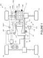
- a hybrid electric vehicle 100 is provided as shown in FIG. 1 .
- the vehicle 100 has an engine 121 coupled to a belt integrated starter generator (BISG) 123B.
- the BISG 123B may also be referred to as a belt integrated (or belt mounted) motor generator and is operable to crank the engine 121 when starting is required.
- a dedicated starter motor may be provided.
- a BISG may be provided but a separate starter motor is employed for starting the engine 121.
- the engine 121 is coupled in turn to a crankshaft-integrated starter/generator (CIMG) 123C by means of a clutch 122.
- the clutch 122 may also be referred to as a K0 clutch 122.
- the CIMG 123C is integrated into a housing of a transmission 124 which is in turn coupled to a driveline 130 of the vehicle 100 thereby to drive a pair of front wheels 111, 112 and a pair of rear wheels 114, 115 of the vehicle 100.
- the driveline 130 in combination with the transmission 124, CIMG 123C, clutch 122, engine 121 and BISG 123B may be considered to form part of a powertrain 131 of the vehicle 100.
- Wheels 111, 112, 114, 115 arranged to be driven by the driveline 130 may also be considered to form part of the powertrain 131.
- the driveline 130 may be arranged to drive the pair of front wheels 111, 112 only or the pair of rear wheels 114, 115 only, or to be switchable between a two wheel drive mode in which the front or rear wheels only are driven and a four wheel drive mode in which the front and rear wheels are driven.
- the BISG 123B and CIMG 123C are arranged to be electrically coupled to a charge storage module 150 having a battery and an inverter.
- the module 150 is operable to supply the BISG 123B and/or CIMG 123C with electrical power when one or both are operated as propulsion motors.
- the module 150 may receive and store electrical power generated by the BISG 123B and/or CIMG 123C when one or both are operated as electrical generators.
- the CIMG 123C and BISG 123B may be configured to generate different electrical potentials to one another.
- each is connected to a respective inverter adapted to operate at the corresponding potential of the CIMG 123C or BISG 123B.
- Each inverter may have a respective battery associated therewith.
- the CIMG 123C and BISG 123B may be coupled to a single inverter which is adapted to receive charge from the CIMG 123C and BISG 123B at the respective potentials and to store the charge in a single battery. Other arrangements are also useful.
- the BISG 123B has an electric machine 123BM that is drivably coupled to a crankshaft 121C of the engine 121 by means of a belt 123BB.
- the BISG 123B is operable to provide torque to the crankshaft 121C when it is required to start the engine 121 or when it is required to provide torque-assist to the driveline 130 as discussed in further detail below.
- the vehicle 100 has a vehicle controller 140 operable to command a powertrain controller 141PT to control the engine 121 to switch on or off and to generate a required amount of torque.
- the vehicle controller 140 is also operable to command the powertrain controller 141PT to control the BISG 123B to apply a required value of positive or negative torque (operating as a propulsion motor or a generator) to the engine 121.
- the vehicle controller 140 may command the CIMG 123C to apply a required value of positive or negative torque (again operating as a propulsion motor or a generator) to the driveline 130 via the transmission 124.
- the vehicle has an accelerator pedal 171 and a brake pedal 172.
- the accelerator pedal 171 provides an output signal to the vehicle controller 140 indicative of an amount by which the pedal 171 is depressed.
- the vehicle controller 140 is arranged to determine the amount of driver demanded torque based on the accelerator pedal position and one or more other vehicle parameters including engine speed W.
- the powertrain controller 141PT is arranged to receive the accelerator pedal position signal and calculate the amount of driver demanded torque.
- the vehicle 100 of FIG. 1 is operable by the vehicle controller 140 in an electric vehicle (EV) mode in which the clutch 122 is open and the crankshaft 121C is stationary.
- EV mode the CIMG 123C is operable to apply positive or negative torque to the driveline 130 via the transmission 124. Negative torque may be applied for example when regenerative braking is required under the control of a brake controller 142B.
- the powertrain 131 is operable in one of a plurality of parallel modes in which the engine 121 is switched on and the clutch 122 is closed.
- the parallel modes include a 'parallel boost' mode in which the CIMG 123C is operated as a motor to provide drive torque to the driveline 130 in addition to the torque provided by the engine 121.
- the powertrain 131 is operated in the parallel boost configuration when the amount of driver demanded torque exceeds the maximum torque available from the engine 121.
- the amount of additional torque available from the CIMG 123C may be determined in dependence on the vehicle configuration as described in more detail below. It is to be understood that the feature of torque boost increases the available drive torque beyond that which is available from the engine 121 alone.
- the parallel modes also include a parallel torque filling mode and a parallel torque assist mode.
- the parallel torque filling mode is a mode in which the CIMG 123C delivers drive torque to the driveline 130 in addition to the engine 121 in order to meet driver demand for torque more quickly than if the engine 121 alone delivers drive torque. Torque filling provides the benefit that driver torque demand may be satisfied more quickly, improving a responsiveness of the vehicle to an increase in torque demand.
- torque filling is implemented when a rate of increase of driver torque demand relative to the amount of torque delivered by the engine 121 exceeds a prescribed value. Once driver torque demand has been satisfied, the amount of torque delivered by the CIMG 123C decreases as the amount of torque delivered by the engine 121 increases to meet driver demand substantially entirely, without a requirement for additional torque from the CIMG 123C.
- Torque-assist parallel mode the CIMG 123C provides steady-state drive torque in addition to the engine 121 in order to relieve loading on the engine 121. This may assist in reducing fuel consumption and/or vehicle emissions. Torque-assist may be considered to be distinct from 'torque filling', the latter being employed in a transient manner when an increase in drive torque is required.
- the powertrain 131 may alternatively be operated in a parallel recharge mode in which the CIMG 123C is driven as a generator by the engine 121 to recharge the charge storage module 150.
- the vehicle 100 has an electrically powered climate control system 180 that is arranged to draw electrical power from the charge storage module 150 when required.
- the climate control system 180 represents a non-essential auxiliary electrical load.
- non-essential is meant that the vehicle 100 is still capable of driving whether or not the climate control system 180 is operational.
- One or more other non-essential auxiliary electrical systems 182 may also be present.
- the vehicle 100 also has 'essential' electrical loads which are always provided with electrical power.
- the essential loads include loads for powering an HMI system and external lighting loads such as headlamps, brake lights and the like. In some embodiments, the essential loads may be denied power only if the provision of power to the essential loads would otherwise cause the engine 121 to stall.
- the controller 140 is configured to ensure that at least a prescribed proportion of a maximum powertrain torque capability at a given moment in time is available to generate power to drive the one or more auxiliary loads 180, 182 even when an amount of demanded drive torque to one or more wheels is equal to or exceeds the maximum available powertrain torque capability.
- torque may be referred to as driver demanded torque, although in some embodiments it may be provided by a speed control system such as a cruise control system in instead of directly from a driver, via the accelerator pedal 171.
- the controller 140 ensures that up to 10% of the maximum available powertrain torque is available to drive the one or mode auxiliary loads 180, 182. Thus, up to 90% of the maximum available powertrain torque is available to drive the one or more wheels, subject to any inherent powertrain losses. Other proportions of maximum available powertrain torque are also useful such as 5%, 15% or any other suitable proportion.
- controller 140 is configured to ensure that at least some powertrain energy is supplied to meet the demand of one or more auxiliary loads when the one or more auxiliary loads so demand, even at relatively high levels of wheel drive torque demand.
- a priority hierarchy may be set as between the auxiliary loads, such that a prescribed amount or proportion of the available torque or energy for the auxiliary loads is made available to one or more loads in preference to one or more other loads.
- An electric winch for example, might be given priority over a load associated with a climate control system such as an air-conditioning compressor.
- any auxiliary load demand placed on the powertrain is met substantially in full, up to the powertrain's maximum capability although a cap may be placed on the amount of torque that may be delivered to one or more auxiliary loads in some embodiments.
- the amount of delivered powertrain wheel drive torque and delivered auxiliary load torque is set according to the rule that the amount of delivered powertrain wheel drive torque is guaranteed to be up to a value of 90% of the maximum available powertrain torque and the amount of delivered auxiliary load torque is guaranteed to be up to a value of 10% of the maximum available powertrain torque.
- the amount of one of the delivered powertrain wheel drive torque and delivered auxiliary load torque may be higher than 90% and 10%, respectively, provided the torque demand by the other has been met in full.
- the powertrain wheel drive torque demand is 95% of the maximum available and the amount of auxiliary load torque demand is 7% of the maximum available, the auxiliary load torque demand is fully satisfied and the remaining 93% of available powertrain torque is used to meet the majority of the powertrain wheel drive torque demand.
- the amount of delivered powertrain wheel drive torque is permitted to have a larger proportion of the available powertrain torque than if the speed is above the prescribed minimum speed.
- the amount of delivered powertrain wheel drive torque is permitted to have a value up to 100% of the available powertrain torque if so demanded.
- Other values are also useful. This is so as to provide enhanced vehicle acceleration at relatively low speeds.
- the prescribed minimum vehicle speed may be around 20 to 30kph although other values are also useful.
- a deviation from the guaranteed amounts may also be useful in dependence on engine speed in a manner corresponding to that for vehicle speed described above,
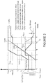
- FIG. 2 is a plot of demanded powertrain wheel drive torque TQWd, actual delivered powertrain wheel drive torque TQWa, demanded auxiliary load torque TQLd, actual delivered auxiliary load torque TQLa and total actual delivered powertrain torque TQTa as a function of time.
- the torque values may be defined in terms of wheel torque or crankshaft torque. Crankshaft torque may be more useful in some embodiments since it may be more conveniently measured, and a conversion to wheel torque is not required.
- the maximum available powertrain torque is indicated Tmax in FIG. 2 .
- the threshold value of powertrain torque Tthresh that is reserved for powertrain wheel drive torque is also shown.
- the difference Tmax-Tthresh is the amount of powertrain torque that is reserved for the auxiliary loads, Tres. It is to be understood that in some embodiments the controller 140 is configured to ensure that the load torque placed on the powertrain cannot exceed the maximum engine torque under any circumstances. This in turn ensures that the engine 121 cannot be caused to stall due to load torque placed on the engine 121.
- TQLd increases abruptly by an amount (T3-T2) as shown in FIG. 2 .
- T3-T2 the total powertrain torque demand
- TQLd+TQWd is still less than Tmax and therefore TQLd and TQWd are both met.
- TQLd At time t4 the sum of TQLd and TQWd begins to exceed Tmax, whilst the value of TQWa is still less than Tthresh. Accordingly, in order to satisfy the requirement that the powertrain wheel drive torque demand must be satisfied at all times up to the reserved amount Tthresh, the amount of actual delivered auxiliary load torque TQLa begins to reduce even though TQLd remains the same.
- TQWa becomes equal to Tthresh. Accordingly, the controller 140 does not allow TQWa to increase any further, and the value of TQLa is no longer decreased.
- TQLd begins to decrease, until at time t6 the value of TQLd falls below the reserved amount Tres. TQLd is therefore met in full, whilst the value of TQWa is increased in proportion to the decrease in TQLa below the reserved amount Tres. Accordingly, a greater proportion of TQWd is met than that specified by Tthresh. Thus, the value of TQWa exceeds Tthresh during the period for which TQLa is less than Tres and TQWd exceeds Tthresh.
- Tthresh is 90% and Tres is therefore 10%.
- Tres is therefore 10%.
- other values are also useful.
- Embodiments of the present invention have the advantage that a certain prescribed amount of maximum powertrain torque, which may be a prescribed proportion or an absolute amount, may be reserved for the provision of powertrain wheel drive torque for driving one or more driving wheels and a corresponding amount reserved for the provision of auxiliary load torque, for driving one or more auxiliary loads.
- a certain prescribed amount of maximum powertrain torque which may be a prescribed proportion or an absolute amount
- embodiments of the present invention reserve a prescribed amount of powertrain torque for powering the one or more auxiliary loads.
- powering the one or more loads may be accomplished by direct mechanical coupling of the loads to the powertrain in some embodiments.
- an auxiliary load such as a compressor of an air-conditioning system may be permitted to apply to the powertrain a torque load of up to the amount that is determined by the controller 140 to be permitted.
- an electrical generator may be permitted to apply a torque loading to the powertrain up to the permitted amount, in order to provide the electrical load with at least some electrical power.
- powering of the one or more loads may be accomplished by operating the CIMG 123C as a generator. Accordingly, powertrain boost torque that would otherwise be provided by the CIMG 123C operating as a motor, will be unavailable. Accordingly, the maximum powertrain torque value may be deemed to be that which may be developed by the engine 121 alone. Accordingly the available powertrain wheel drive torque and available auxiliary load torque may be determined to be corresponding proportions of the maximum torque that the engine 121 is capable of developing, rather than the maximum torque the powertrain 131 as a whole is capable of developing, including engine 121 and the CIMG 123C operated as a motor.
- the BISG 123B may be employed to generate electrical power to power one or more of the one or more auxiliary loads 180, 182.
- FIG. 3 shows a schematic diagram of a portion of the controller 140 implementing an embodiment of the present invention.
- the functionality illustrated in FIG. 3 is implemented by the controller 140 in computer program code and will be described with respect to function blocks for the purpose of ease of understanding.
- the skilled person will recognise that the functionality may be implemented in computer program code in any one of a number of different ways, or in a dedicated hardware circuit.
- the function performed by the portion of the controller 140 illustrated in FIG. 3 receives an input signal in respect of the amount of demanded auxiliary load torque, 'auxiliary request' 201, the amount of demanded powertrain wheel torque, 'driver request' 203 and a reference or 'threshold' torque value 205.
- the signals 201, 203, 205 each have a value between 0 and 1, representing fractions of the maximum available powertrain torque Tmax at a given moment in time.
- Signal 201 is input to a minimiser function block 211 that outputs the lower of signal 201 and a further signal input thereto.
- the further signal input to the minimiser function block 211 is the larger of a difference between the threshold signal 205 and 1 (calculated by function block 213) and the difference between driver request signal 203 and 1 (calculated by function block 215).
- the signal output by the minimiser function block 211 is the arbitrated auxiliary load torque value, i.e. the value of auxiliary load torque that will be actually delivered by the powertrain 131.
- Driver request signal 203 is also fed to a further minimiser function block 223 that outputs the smaller of signal 203 and a further signal input thereto.
- the further signal is the larger of the threshold signal 205 and a difference between auxiliary request signal 201 and 1.
- the signal output by minimiser function block 223 is an arbitrated driver requested torque value or delivered wheel drive torque value, i.e. the value of wheel drive torque that will be actually delivered by the powertrain 131.
- the value of threshold signal 205 is determined by reference to a speed of the engine 121 and a speed of the vehicle 100. Signals 301 and 303 correspond respectively to the engine speed and vehicle speed. The signals 301, 303 are input to a look up table (LUT) function block 305 that outputs a value of the threshold signal 205.
- LUT look up table
- controller 140 is configured to store computer program code for causing one or more computing devices of the controller 140 to perform the method of vehicle control described herein. It is to be understood that a controller according to an embodiment of the present invention may be provided by a plurality of computing devices. The functionality described as being performed by the controller may be performed by a plurality of computing devices, control modules or the like, optionally at different physical locations of a vehicle.
- controller 140 is configured to store computer program code for causing one or more computing devices of the controller 140 to perform the method of vehicle control described herein. It is to be understood that a controller according to an embodiment of the present invention may be provided by a plurality of computing devices. The functionality described as being performed by the controller may be performed by a plurality of computing devices, control modules or the like, optionally at different physical locations of a vehicle.
Landscapes
- Engineering & Computer Science (AREA)
- Chemical & Material Sciences (AREA)
- Combustion & Propulsion (AREA)
- Transportation (AREA)
- Mechanical Engineering (AREA)
- Automation & Control Theory (AREA)
- Electric Propulsion And Braking For Vehicles (AREA)
- Hybrid Electric Vehicles (AREA)
- Control Of Vehicle Engines Or Engines For Specific Uses (AREA)
Description
- The present invention relates to a controller for a hybrid electric vehicle. In particular but not exclusively, embodiments of the present invention relate to a controller for a hybrid electric vehicle operable in a parallel mode.
- It is known to provide a hybrid electric vehicle having an internal combustion engine operable to provide drive torque to drive the vehicle and an electrical propulsion motor operable to provide drive torque when the vehicle is operated in an electric vehicle (EV) mode. A vehicle control system determines when to switch the internal combustion engine on or off, and when to open or close a clutch K0 between the engine and a transmission. In some vehicles the electric propulsion motor is integrated into the transmission.
- It is also known to provide an electric machine as a starter for cranking the engine when an engine start is required. Known starters include belt-integrated starter/generators. Such devices are operable as electrical generators driven by the engine as well as a starter.
US5893272 describes a known vehicle implementing a method for controlling a compressor of a motor vehicle air conditioner that is designed for variable power draw and is driveable by the vehicle drive. The power draw of the compressor is subject to an upper limit that is set variably as a function of the difference between the maximum drive torque that the vehicle drive can deliver and the drive torque that is required to drive the vehicle. During a vehicle acceleration manoeuvre, the air conditioning power of the air conditioner is reduced only to the degree required to reach the desired acceleration. -
EP1833160 describes a known vehicle in which a battery requiring power generation determining unit that is operable to determine first power required by the battery depending on a battery condition. An electric component using power determining unit (11) is operable to determine second power used by the electric components. An feeding indispensable power determining unit is operable to determine feeding indispensable power. A power generation determining unit (11) is operable to determine a first power generation to be generated by the generator based on the first power, the second power, and the feeding indispensable power. The feeding indispensable power determining unit determines the feeding indispensable power depending on a running mode of the vehicle. - Embodiments of the invention may be understood with reference to the appended claims. Aspects of the present invention provide a control system, a vehicle and a method.
- In one aspect of the invention for which protection is sought there is provided a controller for a vehicle according to
claim 1. - Embodiments of the present invention have the advantage that one or more of the auxiliary loads may be provided with powertrain torque even when the total powertrain torque demand exceeds the available powertrain torque. User enjoyment of a driving experience may therefore be enhanced in some embodiments since at least some power is available to drive one or more of the auxiliary loads. The auxiliary loads may include for example a climate control system arranged to maintain a vehicle cabin at an acceptable temperature. If an electrically powered climate control system is denied power by the powertrain and must rely instead on power from the energy storage means, the energy storage means may become exhausted and the climate control system rendered inoperable. Such a situation could occur for example if a heavily laden vehicle is driving up a long incline and powertrain torque demand exceeds the available torque.
- Rather than deny the climate control system any power, in embodiments of the present invention the controller reserves a prescribed amount of powertrain torque, minimum auxiliary load powertrain torque amount, optionally a prescribed proportion or a prescribed absolute amount, in order to allow the climate control system to receive at least some power so that it can continue to operate. The amount reserved may be an amount that is small compared with total powertrain torque, such as around 10% of total powertrain torque, so that any impact on powertrain performance is also relatively small.
- In some embodiments, the amount of power reserved for the climate control system may be determined at least in part in dependence on a temperature value, optionally an external ambient temperature value.
- In an embodiment, the prescribed amount of powertrain torque, minimum auxiliary load powertrain torque, may be determined by the controller in dependence at least in part on one or more vehicle operating conditions.
- In another embodiment, the prescribed amount of powertrain torque, minimum auxiliary load powertrain torque, may be determined at least in part in dependence on vehicle speed.
- Optionally, the prescribed minimum auxiliary load powertrain torque amount is reduced when vehicle speed is below a prescribed threshold value.
- This feature has the advantage that increased powertrain drive torque may be made available to one or more wheels when a vehicle accelerates from a stationary condition or from a relatively low speed. Thus, any reduction in vehicle performance when accelerating from rest or from a relatively low speed that would otherwise be experienced may be reduced or substantially eliminated.
- In an embodiment, the prescribed minimum auxiliary load powertrain torque amount may be determined at least in part in dependence on engine speed.
- The prescribed minimum auxiliary load powertrain torque amount may be reduced when engine speed is below a prescribed value, indicating the vehicle may be moving at a relatively low speed, or may be stationary. This feature enables an increase in the rate of angular acceleration of a driveshaft of the engine to higher speeds when vehicle acceleration is required, improving vehicle performance and user enjoyment.
- In another embodiment, the prescribed minimum auxiliary load powertrain torque amount may be determined at least in part in dependence on driving surface gradient.
- Optionally, the prescribed minimum auxiliary load powertrain torque amount is determined at least in part in dependence on vehicle load, being an amount of powertrain loading due to carried or towed mass.
- That is, by vehicle loading is meant a load on the powertrain due to mass carried or towed by the vehicle. The prescribed minimum auxiliary load powertrain torque amount may in addition be dependent on relative weight distribution between two or more axles of the vehicle.
- Optionally, the prescribed minimum auxiliary load powertrain torque amount may be determined as a prescribed proportion of total available powertrain torque or as an absolute amount of powertrain torque.
- The controller may be configured to control a parallel hybrid electric vehicle having electric propulsion means powered by energy storage means and electric generator means operable to be driven by the engine to recharge the energy storage means.
- Application of aspects of the present invention to a hybrid electric vehicle may be particularly advantageous since an engine of the vehicle may be required to support charging of an energy storage means such as a battery in addition to providing propulsion (drive) torque, in the case of a parallel hybrid vehicle.
- The controller may be operable to cause the electric generator means to generate electrical power to power the auxiliary load such that the amount of torque loading placed on the powertrain by the generator means does not exceed the prescribed minimum auxiliary load powertrain torque amount.
- In a further aspect of the invention for which protection is sought there is provided a vehicle according to claim 11.
- In one aspect of the invention for which protection is sought there is provided a method of controlling a vehicle according to claim 12.
- In an aspect of the invention for which protection is sought there is provided a computer readable medium according to claim 13.
- Within the scope of the invention as claimed it is envisaged that the various aspects, embodiments, examples, features and alternatives set out in the preceding paragraphs and/or in the following description and drawings may be taken independently or in any combination. Features described with reference to one embodiment are applicable to all embodiments, unless there is incompatibility of features.
- Embodiments of the invention will now be described with reference to the accompanying figures in which:
-
FIGURE 1 is a schematic illustration of a hybrid electric vehicle according to an embodiment of the present invention; -
FIGURE 2 is a plot of various powertrain torque demands as a function of time in a vehicle according to an embodiment of the present invention, illustrating operation of the vehicle; -
FIGURE 3 is a schematic diagram of a portion of acontroller 140 according to an embodiment of the present invention; and -
FIGURE 4 is a schematic illustration of a further portion of acontroller 140 according to an embodiment of the present invention. - In one embodiment of the invention a hybrid
electric vehicle 100 is provided as shown inFIG. 1 . Thevehicle 100 has anengine 121 coupled to a belt integrated starter generator (BISG) 123B. The BISG 123B may also be referred to as a belt integrated (or belt mounted) motor generator and is operable to crank theengine 121 when starting is required. In addition or instead, a dedicated starter motor may be provided. In some embodiments therefore, a BISG may be provided but a separate starter motor is employed for starting theengine 121. Theengine 121 is coupled in turn to a crankshaft-integrated starter/generator (CIMG) 123C by means of aclutch 122. Theclutch 122 may also be referred to as aK0 clutch 122. - The
CIMG 123C is integrated into a housing of atransmission 124 which is in turn coupled to adriveline 130 of thevehicle 100 thereby to drive a pair offront wheels rear wheels vehicle 100. Thedriveline 130 in combination with thetransmission 124,CIMG 123C, clutch 122,engine 121 andBISG 123B may be considered to form part of apowertrain 131 of thevehicle 100.Wheels driveline 130 may also be considered to form part of thepowertrain 131. - It is to be understood that other arrangements are also useful. For example the
driveline 130 may be arranged to drive the pair offront wheels rear wheels - The
BISG 123B andCIMG 123C are arranged to be electrically coupled to acharge storage module 150 having a battery and an inverter. Themodule 150 is operable to supply theBISG 123B and/orCIMG 123C with electrical power when one or both are operated as propulsion motors. Similarly, themodule 150 may receive and store electrical power generated by theBISG 123B and/orCIMG 123C when one or both are operated as electrical generators. In some embodiments, theCIMG 123C andBISG 123B may be configured to generate different electrical potentials to one another. Accordingly, in some embodiments each is connected to a respective inverter adapted to operate at the corresponding potential of theCIMG 123C orBISG 123B. Each inverter may have a respective battery associated therewith. In some alternative embodiments theCIMG 123C andBISG 123B may be coupled to a single inverter which is adapted to receive charge from theCIMG 123C andBISG 123B at the respective potentials and to store the charge in a single battery. Other arrangements are also useful. - As noted above, the
BISG 123B has an electric machine 123BM that is drivably coupled to acrankshaft 121C of theengine 121 by means of a belt 123BB. TheBISG 123B is operable to provide torque to thecrankshaft 121C when it is required to start theengine 121 or when it is required to provide torque-assist to thedriveline 130 as discussed in further detail below. - The
vehicle 100 has avehicle controller 140 operable to command a powertrain controller 141PT to control theengine 121 to switch on or off and to generate a required amount of torque. Thevehicle controller 140 is also operable to command the powertrain controller 141PT to control theBISG 123B to apply a required value of positive or negative torque (operating as a propulsion motor or a generator) to theengine 121. Similarly, thevehicle controller 140 may command theCIMG 123C to apply a required value of positive or negative torque (again operating as a propulsion motor or a generator) to thedriveline 130 via thetransmission 124. - The vehicle has an
accelerator pedal 171 and abrake pedal 172. Theaccelerator pedal 171 provides an output signal to thevehicle controller 140 indicative of an amount by which thepedal 171 is depressed. Thevehicle controller 140 is arranged to determine the amount of driver demanded torque based on the accelerator pedal position and one or more other vehicle parameters including engine speed W. In some embodiments, the powertrain controller 141PT is arranged to receive the accelerator pedal position signal and calculate the amount of driver demanded torque. - The
vehicle 100 ofFIG. 1 is operable by thevehicle controller 140 in an electric vehicle (EV) mode in which the clutch 122 is open and thecrankshaft 121C is stationary. In EV mode theCIMG 123C is operable to apply positive or negative torque to thedriveline 130 via thetransmission 124. Negative torque may be applied for example when regenerative braking is required under the control of abrake controller 142B. - The
powertrain 131 is operable in one of a plurality of parallel modes in which theengine 121 is switched on and the clutch 122 is closed. The parallel modes include a 'parallel boost' mode in which theCIMG 123C is operated as a motor to provide drive torque to thedriveline 130 in addition to the torque provided by theengine 121. In the present embodiment thepowertrain 131 is operated in the parallel boost configuration when the amount of driver demanded torque exceeds the maximum torque available from theengine 121. The amount of additional torque available from theCIMG 123C may be determined in dependence on the vehicle configuration as described in more detail below. It is to be understood that the feature of torque boost increases the available drive torque beyond that which is available from theengine 121 alone. - The parallel modes also include a parallel torque filling mode and a parallel torque assist mode. The parallel torque filling mode is a mode in which the
CIMG 123C delivers drive torque to thedriveline 130 in addition to theengine 121 in order to meet driver demand for torque more quickly than if theengine 121 alone delivers drive torque. Torque filling provides the benefit that driver torque demand may be satisfied more quickly, improving a responsiveness of the vehicle to an increase in torque demand. - In the present embodiment torque filling is implemented when a rate of increase of driver torque demand relative to the amount of torque delivered by the
engine 121 exceeds a prescribed value. Once driver torque demand has been satisfied, the amount of torque delivered by theCIMG 123C decreases as the amount of torque delivered by theengine 121 increases to meet driver demand substantially entirely, without a requirement for additional torque from theCIMG 123C. - In the torque-assist parallel mode the
CIMG 123C provides steady-state drive torque in addition to theengine 121 in order to relieve loading on theengine 121. This may assist in reducing fuel consumption and/or vehicle emissions. Torque-assist may be considered to be distinct from 'torque filling', the latter being employed in a transient manner when an increase in drive torque is required. - The
powertrain 131 may alternatively be operated in a parallel recharge mode in which theCIMG 123C is driven as a generator by theengine 121 to recharge thecharge storage module 150. - The
vehicle 100 has an electrically poweredclimate control system 180 that is arranged to draw electrical power from thecharge storage module 150 when required. Theclimate control system 180 represents a non-essential auxiliary electrical load. By non-essential is meant that thevehicle 100 is still capable of driving whether or not theclimate control system 180 is operational. One or more other non-essential auxiliaryelectrical systems 182 may also be present. It is to be understood that thevehicle 100 also has 'essential' electrical loads which are always provided with electrical power. The essential loads include loads for powering an HMI system and external lighting loads such as headlamps, brake lights and the like. In some embodiments, the essential loads may be denied power only if the provision of power to the essential loads would otherwise cause theengine 121 to stall. - It is to be understood that in the present embodiment the
controller 140 is configured to ensure that at least a prescribed proportion of a maximum powertrain torque capability at a given moment in time is available to generate power to drive the one or moreauxiliary loads accelerator pedal 171. - In the present embodiment, the
controller 140 ensures that up to 10% of the maximum available powertrain torque is available to drive the one or modeauxiliary loads - It is to be understood that whilst reference is made herein to powertrain torque, reference may alternatively be made to powertrain power, for example as measured in Watts or kiloWatts. Importantly, the
controller 140 is configured to ensure that at least some powertrain energy is supplied to meet the demand of one or more auxiliary loads when the one or more auxiliary loads so demand, even at relatively high levels of wheel drive torque demand. - A priority hierarchy may be set as between the auxiliary loads, such that a prescribed amount or proportion of the available torque or energy for the auxiliary loads is made available to one or more loads in preference to one or more other loads. An electric winch, for example, might be given priority over a load associated with a climate control system such as an air-conditioning compressor.
- In the case that no wheel drive torque is being demanded from the powertrain, any auxiliary load demand placed on the powertrain is met substantially in full, up to the powertrain's maximum capability although a cap may be placed on the amount of torque that may be delivered to one or more auxiliary loads in some embodiments.
- If a sum of the powertrain wheel drive torque demand and auxiliary load torque demand does not exceed the maximum available powertrain torque, both torque demands are satisfied regardless of their relative values.
- However, if the total powertrain torque demand exceeds the maximum available amount, the amount of delivered powertrain wheel drive torque and delivered auxiliary load torque is set according to the rule that the amount of delivered powertrain wheel drive torque is guaranteed to be up to a value of 90% of the maximum available powertrain torque and the amount of delivered auxiliary load torque is guaranteed to be up to a value of 10% of the maximum available powertrain torque. The amount of one of the delivered powertrain wheel drive torque and delivered auxiliary load torque may be higher than 90% and 10%, respectively, provided the torque demand by the other has been met in full. Thus if the powertrain wheel drive torque demand is 95% of the maximum available and the amount of auxiliary load torque demand is 7% of the maximum available, the auxiliary load torque demand is fully satisfied and the remaining 93% of available powertrain torque is used to meet the majority of the powertrain wheel drive torque demand.
- It is to be understood that, under certain exceptional conditions, a deviation from the guaranteed amounts may be permitted. In the present embodiment, if the vehicle is stationary or travelling at a speed that is below a prescribed minimum vehicle speed, the amount of delivered powertrain wheel drive torque is permitted to have a larger proportion of the available powertrain torque than if the speed is above the prescribed minimum speed. In the present embodiment, the amount of delivered powertrain wheel drive torque is permitted to have a value up to 100% of the available powertrain torque if so demanded. Other values are also useful. This is so as to provide enhanced vehicle acceleration at relatively low speeds. The prescribed minimum vehicle speed may be around 20 to 30kph although other values are also useful.
- A deviation from the guaranteed amounts may also be useful in dependence on engine speed in a manner corresponding to that for vehicle speed described above,
- An example of operation of a
vehicle 100 according to an embodiment of the present invention will now be described by reference toFIG. 2. FIG. 2 is a plot of demanded powertrain wheel drive torque TQWd, actual delivered powertrain wheel drive torque TQWa, demanded auxiliary load torque TQLd, actual delivered auxiliary load torque TQLa and total actual delivered powertrain torque TQTa as a function of time. The torque values may be defined in terms of wheel torque or crankshaft torque. Crankshaft torque may be more useful in some embodiments since it may be more conveniently measured, and a conversion to wheel torque is not required. - The maximum available powertrain torque is indicated Tmax in
FIG. 2 . The threshold value of powertrain torque Tthresh that is reserved for powertrain wheel drive torque is also shown. The difference Tmax-Tthresh is the amount of powertrain torque that is reserved for the auxiliary loads, Tres. It is to be understood that in some embodiments thecontroller 140 is configured to ensure that the load torque placed on the powertrain cannot exceed the maximum engine torque under any circumstances. This in turn ensures that theengine 121 cannot be caused to stall due to load torque placed on theengine 121. - Between times t1 and t2, TQWd is zero and the demanded auxiliary load torque TQLd is fully satisfied, i.e. TQLa=TQLd=T1, even though TQLd is greater than the reserved amount Tres.
- At time t2 the amount of demanded powertrain wheel drive torque TQWd begins to increase, and the amount of delivered powertrain wheel drive torque TQWa increases to fully satisfy TQWd.
- At time t3 the amount of TQLd increases abruptly by an amount (T3-T2) as shown in
FIG. 2 . However, the total powertrain torque demand TQLd+TQWd is still less than Tmax and therefore TQLd and TQWd are both met. - At time t4 the sum of TQLd and TQWd begins to exceed Tmax, whilst the value of TQWa is still less than Tthresh. Accordingly, in order to satisfy the requirement that the powertrain wheel drive torque demand must be satisfied at all times up to the reserved amount Tthresh, the amount of actual delivered auxiliary load torque TQLa begins to reduce even though TQLd remains the same.
- At time t5 the value of TQWa becomes equal to Tthresh. Accordingly, the
controller 140 does not allow TQWa to increase any further, and the value of TQLa is no longer decreased. - At time t5' the value of TQLd begins to decrease, until at time t6 the value of TQLd falls below the reserved amount Tres. TQLd is therefore met in full, whilst the value of TQWa is increased in proportion to the decrease in TQLa below the reserved amount Tres. Accordingly, a greater proportion of TQWd is met than that specified by Tthresh. Thus, the value of TQWa exceeds Tthresh during the period for which TQLa is less than Tres and TQWd exceeds Tthresh.
- As noted above, in the present embodiment Tthresh is 90% and Tres is therefore 10%. However, other values are also useful.
- Embodiments of the present invention have the advantage that a certain prescribed amount of maximum powertrain torque, which may be a prescribed proportion or an absolute amount, may be reserved for the provision of powertrain wheel drive torque for driving one or more driving wheels and a corresponding amount reserved for the provision of auxiliary load torque, for driving one or more auxiliary loads. This allows the auxiliary loads to continue to receive at least a certain amount of powertrain torque in order to maintain at least partial functioning of one or more systems associated with the one or more auxiliary loads, even at relatively high values of demanded powertrain wheel drive torque. Thus, rather than terminating the supply of powertrain torque to drive the one or more auxiliary loads when the amount of powertrain wheel torque demand saturates the maximum available powertrain torque, embodiments of the present invention reserve a prescribed amount of powertrain torque for powering the one or more auxiliary loads.
- It is to be understood that powering the one or more loads may be accomplished by direct mechanical coupling of the loads to the powertrain in some embodiments. Thus in a vehicle such as a conventional (non-hybrid) vehicle, or in a hybrid vehicle, an auxiliary load such as a compressor of an air-conditioning system may be permitted to apply to the powertrain a torque load of up to the amount that is determined by the
controller 140 to be permitted. - In the case of an electrical load, an electrical generator may be permitted to apply a torque loading to the powertrain up to the permitted amount, in order to provide the electrical load with at least some electrical power.
- In some alternative embodiments including the present embodiment, powering of the one or more loads may be accomplished by operating the
CIMG 123C as a generator. Accordingly, powertrain boost torque that would otherwise be provided by theCIMG 123C operating as a motor, will be unavailable. Accordingly, the maximum powertrain torque value may be deemed to be that which may be developed by theengine 121 alone. Accordingly the available powertrain wheel drive torque and available auxiliary load torque may be determined to be corresponding proportions of the maximum torque that theengine 121 is capable of developing, rather than the maximum torque thepowertrain 131 as a whole is capable of developing, includingengine 121 and theCIMG 123C operated as a motor. - In some embodiments, the
BISG 123B may be employed to generate electrical power to power one or more of the one or moreauxiliary loads -
FIG. 3 shows a schematic diagram of a portion of thecontroller 140 implementing an embodiment of the present invention. The functionality illustrated inFIG. 3 is implemented by thecontroller 140 in computer program code and will be described with respect to function blocks for the purpose of ease of understanding. The skilled person will recognise that the functionality may be implemented in computer program code in any one of a number of different ways, or in a dedicated hardware circuit. - The function performed by the portion of the
controller 140 illustrated inFIG. 3 receives an input signal in respect of the amount of demanded auxiliary load torque, 'auxiliary request' 201, the amount of demanded powertrain wheel torque, 'driver request' 203 and a reference or 'threshold'torque value 205. Thesignals -
Signal 201 is input to aminimiser function block 211 that outputs the lower ofsignal 201 and a further signal input thereto. - The further signal input to the
minimiser function block 211 is the larger of a difference between thethreshold signal 205 and 1 (calculated by function block 213) and the difference betweendriver request signal 203 and 1 (calculated by function block 215). - The signal output by the
minimiser function block 211 is the arbitrated auxiliary load torque value, i.e. the value of auxiliary load torque that will be actually delivered by thepowertrain 131. -
Driver request signal 203 is also fed to a furtherminimiser function block 223 that outputs the smaller ofsignal 203 and a further signal input thereto. The further signal is the larger of thethreshold signal 205 and a difference betweenauxiliary request signal - The signal output by
minimiser function block 223 is an arbitrated driver requested torque value or delivered wheel drive torque value, i.e. the value of wheel drive torque that will be actually delivered by thepowertrain 131. - The value of
threshold signal 205 is determined by reference to a speed of theengine 121 and a speed of thevehicle 100.Signals signals function block 305 that outputs a value of thethreshold signal 205. - It is to be understood that the
controller 140 is configured to store computer program code for causing one or more computing devices of thecontroller 140 to perform the method of vehicle control described herein. It is to be understood that a controller according to an embodiment of the present invention may be provided by a plurality of computing devices. The functionality described as being performed by the controller may be performed by a plurality of computing devices, control modules or the like, optionally at different physical locations of a vehicle. - It is to be understood that the
controller 140 is configured to store computer program code for causing one or more computing devices of thecontroller 140 to perform the method of vehicle control described herein. It is to be understood that a controller according to an embodiment of the present invention may be provided by a plurality of computing devices. The functionality described as being performed by the controller may be performed by a plurality of computing devices, control modules or the like, optionally at different physical locations of a vehicle. - Throughout the description and claims of this specification, the words "comprise" and "contain" and variations of the words, for example "comprising" and "comprises", means "including but not limited to", and is not intended to (and does not) exclude other moieties, additives, components, integers or steps which fall within the invention as defined by the claims.
- Throughout the description the singular encompasses the plural unless the context otherwise requires. In particular, where the indefinite article is used, the specification is to be understood as contemplating plurality as well as singularity, unless the context requires otherwise.
- Features, integers, characteristics, compounds, chemical moieties or groups described in conjunction with a particular aspect, embodiment or example of the invention are to be understood to be applicable to any other aspect, embodiment or example described herein and encompassed by the claims unless incompatible therewith.
Claims (13)
- A controller (140) for a vehicle (100) having a powertrain (131) comprising an engine (121), the controller (140) being operable to:receive a signal indicative of an amount of powertrain drive torque required to be applied to one or more wheels (111, 112, 114, 115), powertrain wheel drive torque demand; andreceive a signal indicative of an amount of powertrain load torque required to support an auxiliary powertrain load, powertrain auxiliary load torque demand, that is in addition to the powertrain wheel drive torque demand,the controller (140) being operable to limit the amount of powertrain drive torque available to the one or more wheels (111, 112, 114, 115) and to limit the amount of powertrain load torque available to support the auxiliary load charactrized in that when a sum of the amount of powertrain wheel drive torque demand and the amount of auxiliary load torque demand exceeds the available powertrain torque, at least a prescribed minimum auxiliary load powertrain torque amount is available to the auxiliary load such that when an amount of the powertrain wheel drive torque demand saturates the available powertrain torque, the prescribed amount of powertrain torque, providing at least some power, is reserved for powering the auxiliary load.
- A controller (140) according to claim 1 wherein the prescribed amount of powertrain torque, minimum auxiliary load powertrain torque, is determined by the controller (140) in dependence at least in part on one or more vehicle operating conditions.
- A controller (140) according to claim 2 wherein the prescribed amount of powertrain torque, minimum auxiliary load powertrain torque, is determined at least in part in dependence on vehicle speed.
- A controller (140) according to claim 3 wherein the prescribed minimum auxiliary load powertrain torque amount is reduced when vehicle speed is below a prescribed threshold value.
- A controller (140) according to any one of claims 2 to 4 wherein the prescribed minimum auxiliary load powertrain torque amount is determined at least in part in dependence on engine speed.
- A controller (140) according to any one of claims 2 to 5 wherein the prescribed minimum auxiliary load powertrain torque amount is determined at least in part in dependence on driving surface gradient.
- A controller (140) according to any one of claims 2 to 6 wherein the prescribed minimum auxiliary load powertrain torque amount is determined at least in part in dependence on vehicle load, being an amount of powertrain loading due to carried or towed mass.
- A controller (140) according to any preceding claim wherein the prescribed minimum auxiliary load powertrain torque amount is determined as a prescribed proportion of total available powertrain torque or as an absolute amount of powertrain torque.
- A controller (140) according to any preceding claim configured to control a parallel hybrid electric vehicle (100) having electric propulsion means powered by energy storage means (150), and electric generator means operable to be driven by the engine (121) to recharge the energy storage means.
- A controller (140) according to claim 9 operable to cause the electric generator means to generate electrical power to power the auxiliary load such that the amount of torque loading placed on the powertrain by the generator means does not exceed the prescribed minimum auxiliary load powertrain torque amount.
- A vehicle (100) comprising a controller (140) according to any preceding claim.
- A method of controlling a vehicle (100) having a powertrain (131) comprising an engine (121), the method comprising:receiving a signal indicative of an amount of powertrain drive torque required to be applied to one or more wheels (111, 112, 114, 115), powertrain wheel drive torque demand; andreceiving a signal indicative of an amount of powertrain load torque required to support an auxiliary powertrain load, powertrain auxiliary load torque demand, that is in addition to the powertrain wheel drive torque demand,the method comprising limiting the amount of powertrain drive torque available to the one or more wheels (111, 112, 114, 115) and limiting the amount of powertrain load torque available to support the auxiliary load characterized in that when a sum of the amount of powertrain wheel drive torque demand and the amount of auxiliary load torque demand exceeds the available powertrain torque, at least a prescribed minimum auxiliary load powertrain torque amount is available to the auxiliary load such that when an amount of the powertrain wheel drive torque demand saturates the available powertrain torque, the prescribed amount of powertrain torque, providing at least some power, is reserved for powering the auxiliary loads.
- A computer readable medium carrying computer program code for controlling a vehicle (100) to carry out the method of claim 12.
Applications Claiming Priority (2)
| Application Number | Priority Date | Filing Date | Title |
|---|---|---|---|
| GB1314991.9A GB2517685B (en) | 2013-08-21 | 2013-08-21 | Vehicle controller and method |
| PCT/EP2014/067751 WO2015024970A2 (en) | 2013-08-21 | 2014-08-20 | Hybrid electric vehicle controller and method |
Publications (2)
| Publication Number | Publication Date |
|---|---|
| EP3036120A2 EP3036120A2 (en) | 2016-06-29 |
| EP3036120B1 true EP3036120B1 (en) | 2020-10-21 |
Family
ID=49302034
Family Applications (1)
| Application Number | Title | Priority Date | Filing Date |
|---|---|---|---|
| EP14752887.1A Active EP3036120B1 (en) | 2013-08-21 | 2014-08-20 | Hybrid electric vehicle controller and method |
Country Status (4)
| Country | Link |
|---|---|
| US (1) | US9731703B2 (en) |
| EP (1) | EP3036120B1 (en) |
| GB (1) | GB2517685B (en) |
| WO (1) | WO2015024970A2 (en) |
Families Citing this family (8)
| Publication number | Priority date | Publication date | Assignee | Title |
|---|---|---|---|---|
| KR101566736B1 (en) * | 2013-12-26 | 2015-11-06 | 현대자동차 주식회사 | Apparatus and method for controlling full load mode of hybird vehicle |
| RU2678620C1 (en) * | 2015-03-19 | 2019-01-30 | Ниссан Мотор Ко., Лтд. | Device of hybrid transport facility control |
| JP6314953B2 (en) * | 2015-10-16 | 2018-04-25 | トヨタ自動車株式会社 | Control device for hybrid vehicle |
| FR3071463B1 (en) * | 2017-09-27 | 2020-10-16 | Psa Automobiles Sa | TORQUE RECOVERY PROCESS FOR AN ENGINE DURING AUTOMATIC PILOTING |
| US10384665B1 (en) * | 2018-03-15 | 2019-08-20 | Ford Global Technologies, Llc | Methods and system for starting an engine |
| US11110803B2 (en) * | 2019-03-22 | 2021-09-07 | Ford Global Technologies, Llc | Compensation of high voltage loads during pedal lift operation |
| CN114454863B (en) * | 2022-02-23 | 2024-07-12 | 东风康明斯发动机有限公司 | Control method and system for output torque of electric control engine |
| US20260103180A1 (en) * | 2024-10-16 | 2026-04-16 | Ford Global Technologies, Llc | Methods and system to prepare vehicle for performance mode |
Family Cites Families (10)
| Publication number | Priority date | Publication date | Assignee | Title |
|---|---|---|---|---|
| DE19642832C1 (en) * | 1996-10-17 | 1997-09-18 | Daimler Benz Ag | Air-conditioning compressor control method for vehicle |
| DE102004027063A1 (en) * | 2004-06-03 | 2005-12-22 | Zf Friedrichshafen Ag | Method for optimized detection of the transmission input torque in vehicles equipped with auxiliary units on the engine side |
| JP4299288B2 (en) * | 2005-10-11 | 2009-07-22 | トヨタ自動車株式会社 | POWER OUTPUT DEVICE, AUTOMOBILE MOUNTING THE SAME, DRIVE DEVICE, AND CONTROL METHOD FOR POWER OUTPUT DEVICE |
| US7696719B2 (en) * | 2006-03-07 | 2010-04-13 | Fujitsu Ten Limited | Power control apparatus, power control method |
| US9126598B2 (en) * | 2006-06-05 | 2015-09-08 | Deere & Company | Power management for infinitely variable transmission (IVT) equipped machines |
| US8012062B2 (en) * | 2007-09-10 | 2011-09-06 | GM Global Technology Operations LLC | Apparatus and method of engine torque control during power take-off operation in a motor vehicle |
| US8579748B2 (en) * | 2009-04-28 | 2013-11-12 | Nippon Soken, Inc. | In-vehicle power transmission device and power transmission system for vehicle |
| JP2013014155A (en) * | 2011-06-30 | 2013-01-24 | Denso Corp | Clutch protection device |
| US8612078B2 (en) * | 2011-08-08 | 2013-12-17 | Bae Systems Controls Inc. | Parallel hybrid electric vehicle power management system and adaptive power management method and program therefor |
| JP2013123279A (en) * | 2011-12-09 | 2013-06-20 | Honda Motor Co Ltd | Electric vehicle |
-
2013
- 2013-08-21 GB GB1314991.9A patent/GB2517685B/en not_active Expired - Fee Related
-
2014
- 2014-08-20 WO PCT/EP2014/067751 patent/WO2015024970A2/en not_active Ceased
- 2014-08-20 US US14/903,107 patent/US9731703B2/en active Active
- 2014-08-20 EP EP14752887.1A patent/EP3036120B1/en active Active
Non-Patent Citations (1)
| Title |
|---|
| None * |
Also Published As
| Publication number | Publication date |
|---|---|
| US20160167637A1 (en) | 2016-06-16 |
| US9731703B2 (en) | 2017-08-15 |
| GB2517685B (en) | 2017-10-25 |
| GB201314991D0 (en) | 2013-10-02 |
| GB2517685A (en) | 2015-03-04 |
| WO2015024970A3 (en) | 2015-08-06 |
| EP3036120A2 (en) | 2016-06-29 |
| WO2015024970A2 (en) | 2015-02-26 |
Similar Documents
| Publication | Publication Date | Title |
|---|---|---|
| US9731703B2 (en) | Hybrid electric vehicle controller and method | |
| US8818595B2 (en) | Controller for hybrid vehicle | |
| CN104704737B (en) | Power generation control | |
| JP5725037B2 (en) | Vehicle and vehicle control method | |
| CN102958775B (en) | The control setup of motor vehicle driven by mixed power and there is the motor vehicle driven by mixed power of this control setup | |
| CN109624962B (en) | hybrid vehicle | |
| CN106256627B (en) | Method and apparatus for controlling engine start time in hybrid vehicle | |
| JP5729475B2 (en) | Vehicle and vehicle control method | |
| EP2928744A1 (en) | Hybrid electric vehicle control system and method | |
| JP2008150014A (en) | Power generation control method during idling charging of hybrid electric vehicle | |
| KR20140135246A (en) | Electric power generation control system for hybrid automobile | |
| CN105501214B (en) | The method for controlling the battery of mild hybrid electric vehicle | |
| JP5598555B2 (en) | Vehicle and vehicle control method | |
| JP6659459B2 (en) | vehicle | |
| US20170113677A1 (en) | Hybrid vehicle and control method for same | |
| JP2013241129A (en) | Electric power generation control device for hybrid vehicle | |
| US20160193993A1 (en) | Systems and methods for managing vehicular energy consumption | |
| JPH11318002A (en) | Control device for hybrid vehicle | |
| JP2012121555A (en) | Device and method for controlling hybrid vehicle | |
| JP2015107715A (en) | Hybrid vehicle | |
| JP7497124B2 (en) | Electric vehicle control device | |
| JP2014043183A (en) | Hybrid vehicle | |
| JP2017095003A (en) | Hybrid vehicle | |
| JP2017128209A (en) | Hybrid vehicle | |
| JP2023093777A (en) | Hybrid vehicle control device |
Legal Events
| Date | Code | Title | Description |
|---|---|---|---|
| PUAI | Public reference made under article 153(3) epc to a published international application that has entered the european phase |
Free format text: ORIGINAL CODE: 0009012 |
|
| 17P | Request for examination filed |
Effective date: 20160321 |
|
| AK | Designated contracting states |
Kind code of ref document: A2 Designated state(s): AL AT BE BG CH CY CZ DE DK EE ES FI FR GB GR HR HU IE IS IT LI LT LU LV MC MK MT NL NO PL PT RO RS SE SI SK SM TR |
|
| AX | Request for extension of the european patent |
Extension state: BA ME |
|
| DAX | Request for extension of the european patent (deleted) | ||
| STAA | Information on the status of an ep patent application or granted ep patent |
Free format text: STATUS: EXAMINATION IS IN PROGRESS |
|
| 17Q | First examination report despatched |
Effective date: 20190423 |
|
| GRAP | Despatch of communication of intention to grant a patent |
Free format text: ORIGINAL CODE: EPIDOSNIGR1 |
|
| STAA | Information on the status of an ep patent application or granted ep patent |
Free format text: STATUS: GRANT OF PATENT IS INTENDED |
|
| INTG | Intention to grant announced |
Effective date: 20200508 |
|
| GRAS | Grant fee paid |
Free format text: ORIGINAL CODE: EPIDOSNIGR3 |
|
| GRAA | (expected) grant |
Free format text: ORIGINAL CODE: 0009210 |
|
| STAA | Information on the status of an ep patent application or granted ep patent |
Free format text: STATUS: THE PATENT HAS BEEN GRANTED |
|
| AK | Designated contracting states |
Kind code of ref document: B1 Designated state(s): AL AT BE BG CH CY CZ DE DK EE ES FI FR GB GR HR HU IE IS IT LI LT LU LV MC MK MT NL NO PL PT RO RS SE SI SK SM TR |
|
| REG | Reference to a national code |
Ref country code: GB Ref legal event code: FG4D |
|
| REG | Reference to a national code |
Ref country code: CH Ref legal event code: EP |
|
| REG | Reference to a national code |
Ref country code: IE Ref legal event code: FG4D |
|
| REG | Reference to a national code |
Ref country code: DE Ref legal event code: R096 Ref document number: 602014071461 Country of ref document: DE |
|
| REG | Reference to a national code |
Ref country code: AT Ref legal event code: REF Ref document number: 1325486 Country of ref document: AT Kind code of ref document: T Effective date: 20201115 |
|
| REG | Reference to a national code |
Ref country code: AT Ref legal event code: MK05 Ref document number: 1325486 Country of ref document: AT Kind code of ref document: T Effective date: 20201021 |
|
| REG | Reference to a national code |
Ref country code: NL Ref legal event code: MP Effective date: 20201021 |
|
| PG25 | Lapsed in a contracting state [announced via postgrant information from national office to epo] |
Ref country code: GR Free format text: LAPSE BECAUSE OF FAILURE TO SUBMIT A TRANSLATION OF THE DESCRIPTION OR TO PAY THE FEE WITHIN THE PRESCRIBED TIME-LIMIT Effective date: 20210122 Ref country code: RS Free format text: LAPSE BECAUSE OF FAILURE TO SUBMIT A TRANSLATION OF THE DESCRIPTION OR TO PAY THE FEE WITHIN THE PRESCRIBED TIME-LIMIT Effective date: 20201021 Ref country code: FI Free format text: LAPSE BECAUSE OF FAILURE TO SUBMIT A TRANSLATION OF THE DESCRIPTION OR TO PAY THE FEE WITHIN THE PRESCRIBED TIME-LIMIT Effective date: 20201021 Ref country code: NL Free format text: LAPSE BECAUSE OF FAILURE TO SUBMIT A TRANSLATION OF THE DESCRIPTION OR TO PAY THE FEE WITHIN THE PRESCRIBED TIME-LIMIT Effective date: 20201021 Ref country code: PT Free format text: LAPSE BECAUSE OF FAILURE TO SUBMIT A TRANSLATION OF THE DESCRIPTION OR TO PAY THE FEE WITHIN THE PRESCRIBED TIME-LIMIT Effective date: 20210222 Ref country code: NO Free format text: LAPSE BECAUSE OF FAILURE TO SUBMIT A TRANSLATION OF THE DESCRIPTION OR TO PAY THE FEE WITHIN THE PRESCRIBED TIME-LIMIT Effective date: 20210121 |
|
| REG | Reference to a national code |
Ref country code: LT Ref legal event code: MG4D |
|
| PG25 | Lapsed in a contracting state [announced via postgrant information from national office to epo] |
Ref country code: IS Free format text: LAPSE BECAUSE OF FAILURE TO SUBMIT A TRANSLATION OF THE DESCRIPTION OR TO PAY THE FEE WITHIN THE PRESCRIBED TIME-LIMIT Effective date: 20210221 Ref country code: SE Free format text: LAPSE BECAUSE OF FAILURE TO SUBMIT A TRANSLATION OF THE DESCRIPTION OR TO PAY THE FEE WITHIN THE PRESCRIBED TIME-LIMIT Effective date: 20201021 Ref country code: LV Free format text: LAPSE BECAUSE OF FAILURE TO SUBMIT A TRANSLATION OF THE DESCRIPTION OR TO PAY THE FEE WITHIN THE PRESCRIBED TIME-LIMIT Effective date: 20201021 Ref country code: PL Free format text: LAPSE BECAUSE OF FAILURE TO SUBMIT A TRANSLATION OF THE DESCRIPTION OR TO PAY THE FEE WITHIN THE PRESCRIBED TIME-LIMIT Effective date: 20201021 Ref country code: ES Free format text: LAPSE BECAUSE OF FAILURE TO SUBMIT A TRANSLATION OF THE DESCRIPTION OR TO PAY THE FEE WITHIN THE PRESCRIBED TIME-LIMIT Effective date: 20201021 Ref country code: AT Free format text: LAPSE BECAUSE OF FAILURE TO SUBMIT A TRANSLATION OF THE DESCRIPTION OR TO PAY THE FEE WITHIN THE PRESCRIBED TIME-LIMIT Effective date: 20201021 Ref country code: BG Free format text: LAPSE BECAUSE OF FAILURE TO SUBMIT A TRANSLATION OF THE DESCRIPTION OR TO PAY THE FEE WITHIN THE PRESCRIBED TIME-LIMIT Effective date: 20210121 |
|
| PG25 | Lapsed in a contracting state [announced via postgrant information from national office to epo] |
Ref country code: HR Free format text: LAPSE BECAUSE OF FAILURE TO SUBMIT A TRANSLATION OF THE DESCRIPTION OR TO PAY THE FEE WITHIN THE PRESCRIBED TIME-LIMIT Effective date: 20201021 |
|
| REG | Reference to a national code |
Ref country code: DE Ref legal event code: R097 Ref document number: 602014071461 Country of ref document: DE |
|
| PG25 | Lapsed in a contracting state [announced via postgrant information from national office to epo] |
Ref country code: RO Free format text: LAPSE BECAUSE OF FAILURE TO SUBMIT A TRANSLATION OF THE DESCRIPTION OR TO PAY THE FEE WITHIN THE PRESCRIBED TIME-LIMIT Effective date: 20201021 Ref country code: SK Free format text: LAPSE BECAUSE OF FAILURE TO SUBMIT A TRANSLATION OF THE DESCRIPTION OR TO PAY THE FEE WITHIN THE PRESCRIBED TIME-LIMIT Effective date: 20201021 Ref country code: LT Free format text: LAPSE BECAUSE OF FAILURE TO SUBMIT A TRANSLATION OF THE DESCRIPTION OR TO PAY THE FEE WITHIN THE PRESCRIBED TIME-LIMIT Effective date: 20201021 Ref country code: SM Free format text: LAPSE BECAUSE OF FAILURE TO SUBMIT A TRANSLATION OF THE DESCRIPTION OR TO PAY THE FEE WITHIN THE PRESCRIBED TIME-LIMIT Effective date: 20201021 Ref country code: EE Free format text: LAPSE BECAUSE OF FAILURE TO SUBMIT A TRANSLATION OF THE DESCRIPTION OR TO PAY THE FEE WITHIN THE PRESCRIBED TIME-LIMIT Effective date: 20201021 Ref country code: CZ Free format text: LAPSE BECAUSE OF FAILURE TO SUBMIT A TRANSLATION OF THE DESCRIPTION OR TO PAY THE FEE WITHIN THE PRESCRIBED TIME-LIMIT Effective date: 20201021 |
|
| PLBE | No opposition filed within time limit |
Free format text: ORIGINAL CODE: 0009261 |
|
| STAA | Information on the status of an ep patent application or granted ep patent |
Free format text: STATUS: NO OPPOSITION FILED WITHIN TIME LIMIT |
|
| PG25 | Lapsed in a contracting state [announced via postgrant information from national office to epo] |
Ref country code: DK Free format text: LAPSE BECAUSE OF FAILURE TO SUBMIT A TRANSLATION OF THE DESCRIPTION OR TO PAY THE FEE WITHIN THE PRESCRIBED TIME-LIMIT Effective date: 20201021 |
|
| 26N | No opposition filed |
Effective date: 20210722 |
|
| PG25 | Lapsed in a contracting state [announced via postgrant information from national office to epo] |
Ref country code: AL Free format text: LAPSE BECAUSE OF FAILURE TO SUBMIT A TRANSLATION OF THE DESCRIPTION OR TO PAY THE FEE WITHIN THE PRESCRIBED TIME-LIMIT Effective date: 20201021 Ref country code: IT Free format text: LAPSE BECAUSE OF FAILURE TO SUBMIT A TRANSLATION OF THE DESCRIPTION OR TO PAY THE FEE WITHIN THE PRESCRIBED TIME-LIMIT Effective date: 20201021 |
|
| PG25 | Lapsed in a contracting state [announced via postgrant information from national office to epo] |
Ref country code: SI Free format text: LAPSE BECAUSE OF FAILURE TO SUBMIT A TRANSLATION OF THE DESCRIPTION OR TO PAY THE FEE WITHIN THE PRESCRIBED TIME-LIMIT Effective date: 20201021 |
|
| REG | Reference to a national code |
Ref country code: CH Ref legal event code: PL |
|
| PG25 | Lapsed in a contracting state [announced via postgrant information from national office to epo] |
Ref country code: MC Free format text: LAPSE BECAUSE OF FAILURE TO SUBMIT A TRANSLATION OF THE DESCRIPTION OR TO PAY THE FEE WITHIN THE PRESCRIBED TIME-LIMIT Effective date: 20201021 |
|
| REG | Reference to a national code |
Ref country code: BE Ref legal event code: MM Effective date: 20210831 |
|
| PG25 | Lapsed in a contracting state [announced via postgrant information from national office to epo] |
Ref country code: LI Free format text: LAPSE BECAUSE OF NON-PAYMENT OF DUE FEES Effective date: 20210831 Ref country code: CH Free format text: LAPSE BECAUSE OF NON-PAYMENT OF DUE FEES Effective date: 20210831 |
|
| PG25 | Lapsed in a contracting state [announced via postgrant information from national office to epo] |
Ref country code: IS Free format text: LAPSE BECAUSE OF FAILURE TO SUBMIT A TRANSLATION OF THE DESCRIPTION OR TO PAY THE FEE WITHIN THE PRESCRIBED TIME-LIMIT Effective date: 20210221 Ref country code: LU Free format text: LAPSE BECAUSE OF NON-PAYMENT OF DUE FEES Effective date: 20210820 |
|
| PG25 | Lapsed in a contracting state [announced via postgrant information from national office to epo] |
Ref country code: IE Free format text: LAPSE BECAUSE OF NON-PAYMENT OF DUE FEES Effective date: 20210820 Ref country code: BE Free format text: LAPSE BECAUSE OF NON-PAYMENT OF DUE FEES Effective date: 20210831 |
|
| PG25 | Lapsed in a contracting state [announced via postgrant information from national office to epo] |
Ref country code: HU Free format text: LAPSE BECAUSE OF FAILURE TO SUBMIT A TRANSLATION OF THE DESCRIPTION OR TO PAY THE FEE WITHIN THE PRESCRIBED TIME-LIMIT; INVALID AB INITIO Effective date: 20140820 |
|
| PG25 | Lapsed in a contracting state [announced via postgrant information from national office to epo] |
Ref country code: CY Free format text: LAPSE BECAUSE OF FAILURE TO SUBMIT A TRANSLATION OF THE DESCRIPTION OR TO PAY THE FEE WITHIN THE PRESCRIBED TIME-LIMIT Effective date: 20201021 |
|
| P01 | Opt-out of the competence of the unified patent court (upc) registered |
Effective date: 20230528 |
|
| PG25 | Lapsed in a contracting state [announced via postgrant information from national office to epo] |
Ref country code: MK Free format text: LAPSE BECAUSE OF FAILURE TO SUBMIT A TRANSLATION OF THE DESCRIPTION OR TO PAY THE FEE WITHIN THE PRESCRIBED TIME-LIMIT Effective date: 20201021 |
|
| PG25 | Lapsed in a contracting state [announced via postgrant information from national office to epo] |
Ref country code: TR Free format text: LAPSE BECAUSE OF FAILURE TO SUBMIT A TRANSLATION OF THE DESCRIPTION OR TO PAY THE FEE WITHIN THE PRESCRIBED TIME-LIMIT Effective date: 20201021 |
|
| PG25 | Lapsed in a contracting state [announced via postgrant information from national office to epo] |
Ref country code: MT Free format text: LAPSE BECAUSE OF FAILURE TO SUBMIT A TRANSLATION OF THE DESCRIPTION OR TO PAY THE FEE WITHIN THE PRESCRIBED TIME-LIMIT Effective date: 20201021 |
|
| PGFP | Annual fee paid to national office [announced via postgrant information from national office to epo] |
Ref country code: DE Payment date: 20250820 Year of fee payment: 12 |
|
| PGFP | Annual fee paid to national office [announced via postgrant information from national office to epo] |
Ref country code: GB Payment date: 20250821 Year of fee payment: 12 |
|
| PGFP | Annual fee paid to national office [announced via postgrant information from national office to epo] |
Ref country code: FR Payment date: 20250829 Year of fee payment: 12 |