EP3035687A1 - A device and a method for encoding an image and corresponding decoding method and decoding device - Google Patents
A device and a method for encoding an image and corresponding decoding method and decoding device Download PDFInfo
- Publication number
- EP3035687A1 EP3035687A1 EP15198213.9A EP15198213A EP3035687A1 EP 3035687 A1 EP3035687 A1 EP 3035687A1 EP 15198213 A EP15198213 A EP 15198213A EP 3035687 A1 EP3035687 A1 EP 3035687A1
- Authority
- EP
- European Patent Office
- Prior art keywords
- low frequency
- spatial area
- wavelet coefficients
- wavelet
- threshold
- Prior art date
- Legal status (The legal status is an assumption and is not a legal conclusion. Google has not performed a legal analysis and makes no representation as to the accuracy of the status listed.)
- Withdrawn
Links
- 238000000034 method Methods 0.000 title claims abstract description 84
- 230000001131 transforming effect Effects 0.000 claims abstract description 20
- 238000013139 quantization Methods 0.000 claims description 51
- 238000012935 Averaging Methods 0.000 claims description 2
- 238000004891 communication Methods 0.000 description 11
- 238000004590 computer program Methods 0.000 description 10
- 238000010606 normalization Methods 0.000 description 8
- 239000003086 colorant Substances 0.000 description 7
- 230000006870 function Effects 0.000 description 5
- 230000003287 optical effect Effects 0.000 description 5
- 230000015572 biosynthetic process Effects 0.000 description 4
- 238000000354 decomposition reaction Methods 0.000 description 4
- 230000001419 dependent effect Effects 0.000 description 4
- 230000000007 visual effect Effects 0.000 description 4
- 230000003044 adaptive effect Effects 0.000 description 2
- 230000000295 complement effect Effects 0.000 description 2
- 238000005457 optimization Methods 0.000 description 2
- 229920001690 polydopamine Polymers 0.000 description 2
- 238000012545 processing Methods 0.000 description 2
- 239000004065 semiconductor Substances 0.000 description 2
- 238000013459 approach Methods 0.000 description 1
- 238000006243 chemical reaction Methods 0.000 description 1
- 230000006835 compression Effects 0.000 description 1
- 238000007906 compression Methods 0.000 description 1
- 238000012937 correction Methods 0.000 description 1
- 238000012986 modification Methods 0.000 description 1
- 230000004048 modification Effects 0.000 description 1
- 230000008447 perception Effects 0.000 description 1
- 238000001228 spectrum Methods 0.000 description 1
- 230000009466 transformation Effects 0.000 description 1
Images


Classifications
-
- H—ELECTRICITY
- H04—ELECTRIC COMMUNICATION TECHNIQUE
- H04N—PICTORIAL COMMUNICATION, e.g. TELEVISION
- H04N19/00—Methods or arrangements for coding, decoding, compressing or decompressing digital video signals
- H04N19/10—Methods or arrangements for coding, decoding, compressing or decompressing digital video signals using adaptive coding
- H04N19/169—Methods or arrangements for coding, decoding, compressing or decompressing digital video signals using adaptive coding characterised by the coding unit, i.e. the structural portion or semantic portion of the video signal being the object or the subject of the adaptive coding
- H04N19/186—Methods or arrangements for coding, decoding, compressing or decompressing digital video signals using adaptive coding characterised by the coding unit, i.e. the structural portion or semantic portion of the video signal being the object or the subject of the adaptive coding the unit being a colour or a chrominance component
-
- H—ELECTRICITY
- H04—ELECTRIC COMMUNICATION TECHNIQUE
- H04N—PICTORIAL COMMUNICATION, e.g. TELEVISION
- H04N19/00—Methods or arrangements for coding, decoding, compressing or decompressing digital video signals
- H04N19/10—Methods or arrangements for coding, decoding, compressing or decompressing digital video signals using adaptive coding
- H04N19/102—Methods or arrangements for coding, decoding, compressing or decompressing digital video signals using adaptive coding characterised by the element, parameter or selection affected or controlled by the adaptive coding
- H04N19/103—Selection of coding mode or of prediction mode
-
- H—ELECTRICITY
- H04—ELECTRIC COMMUNICATION TECHNIQUE
- H04N—PICTORIAL COMMUNICATION, e.g. TELEVISION
- H04N19/00—Methods or arrangements for coding, decoding, compressing or decompressing digital video signals
- H04N19/10—Methods or arrangements for coding, decoding, compressing or decompressing digital video signals using adaptive coding
- H04N19/102—Methods or arrangements for coding, decoding, compressing or decompressing digital video signals using adaptive coding characterised by the element, parameter or selection affected or controlled by the adaptive coding
- H04N19/124—Quantisation
-
- H—ELECTRICITY
- H04—ELECTRIC COMMUNICATION TECHNIQUE
- H04N—PICTORIAL COMMUNICATION, e.g. TELEVISION
- H04N19/00—Methods or arrangements for coding, decoding, compressing or decompressing digital video signals
- H04N19/10—Methods or arrangements for coding, decoding, compressing or decompressing digital video signals using adaptive coding
- H04N19/102—Methods or arrangements for coding, decoding, compressing or decompressing digital video signals using adaptive coding characterised by the element, parameter or selection affected or controlled by the adaptive coding
- H04N19/124—Quantisation
- H04N19/126—Details of normalisation or weighting functions, e.g. normalisation matrices or variable uniform quantisers
-
- H—ELECTRICITY
- H04—ELECTRIC COMMUNICATION TECHNIQUE
- H04N—PICTORIAL COMMUNICATION, e.g. TELEVISION
- H04N19/00—Methods or arrangements for coding, decoding, compressing or decompressing digital video signals
- H04N19/10—Methods or arrangements for coding, decoding, compressing or decompressing digital video signals using adaptive coding
- H04N19/134—Methods or arrangements for coding, decoding, compressing or decompressing digital video signals using adaptive coding characterised by the element, parameter or criterion affecting or controlling the adaptive coding
- H04N19/146—Data rate or code amount at the encoder output
- H04N19/147—Data rate or code amount at the encoder output according to rate distortion criteria
-
- H—ELECTRICITY
- H04—ELECTRIC COMMUNICATION TECHNIQUE
- H04N—PICTORIAL COMMUNICATION, e.g. TELEVISION
- H04N19/00—Methods or arrangements for coding, decoding, compressing or decompressing digital video signals
- H04N19/10—Methods or arrangements for coding, decoding, compressing or decompressing digital video signals using adaptive coding
- H04N19/169—Methods or arrangements for coding, decoding, compressing or decompressing digital video signals using adaptive coding characterised by the coding unit, i.e. the structural portion or semantic portion of the video signal being the object or the subject of the adaptive coding
- H04N19/18—Methods or arrangements for coding, decoding, compressing or decompressing digital video signals using adaptive coding characterised by the coding unit, i.e. the structural portion or semantic portion of the video signal being the object or the subject of the adaptive coding the unit being a set of transform coefficients
-
- H—ELECTRICITY
- H04—ELECTRIC COMMUNICATION TECHNIQUE
- H04N—PICTORIAL COMMUNICATION, e.g. TELEVISION
- H04N19/00—Methods or arrangements for coding, decoding, compressing or decompressing digital video signals
- H04N19/60—Methods or arrangements for coding, decoding, compressing or decompressing digital video signals using transform coding
- H04N19/63—Methods or arrangements for coding, decoding, compressing or decompressing digital video signals using transform coding using sub-band based transform, e.g. wavelets
Definitions
- a method and a device for encoding an image represented in a perceptual color space are disclosed.
- Corresponding decoding method and decoding device are further disclosed.
- LDR images Low-Dynamic-Range images
- HDR images high-dynamic range images
- pixel values are usually represented in floating-point format (either 32-bit or 16-bit for each component, namely float or half-float).
- the most popular high-dynamic-range file format is openEXR half-float format (16-bit per RGB component, i.e. 48 bits per pixel) or openEXR integer format with a long representation, typically at least 16 bits.
- a method for encoding an image represented in a perceptual color space, wherein the image has at least a luminance component is disclosed.
- the method comprises:
- a method for encoding an image represented in a perceptual color space, wherein the image has at least a luminance component comprises:
- a coding device for encoding an image represented in a perceptual color space, the image having at least a luminance component is disclosed.
- the coding device comprises at least a processor configured to:
- a coding device for encoding an image represented in a perceptual color space, the image having at least a luminance component is disclosed.
- the coding device comprises :
- a coding device for encoding an image represented in a perceptual color space is disclosed, the image having at least a luminance component.
- the coding device comprises at least a processor configured to:
- a coding device for encoding an image represented in a perceptual color space, the image having at least a luminance component is disclosed.
- the coding device comprises :
- the spatial area comprises a single wavelet coefficient and reconstructing a low frequency component for the spatial area of the low frequency subband comprises quantizing and inverse quantizing the single wavelet coefficient.
- the spatial area comprises at least two wavelet coefficients and reconstructing a low frequency component for the spatial area of the low frequency subband comprises averaging the at least two wavelet coefficients into an averaged coefficient, quantizing and inverse quantizing the average coefficient.
- quantizing the wavelet coefficients of the spatial area comprises:
- quantizing the wavelet coefficients in the spatial area comprises:
- the image has at least one chrominance component and the method further comprises:
- the perceptual color space is a CIELAB color space.
- the at least one low frequency subband of wavelet coefficients is divided into spatial areas and the encoding method applies on each spatial area.
- a method for decoding an image having at least a luminance component represented in a perceptual color space comprises:
- a method for decoding an image having at least a luminance component represented in a perceptual color space comprises:
- a decoding device for decoding an image having at least a luminance component represented in a perceptual color space.
- the decoding device comprises at least a processor configured to:
- the decoding device comprises :
- a decoding device for decoding an image having at least a luminance component represented in a perceptual color space.
- the decoding device comprises at least a processor configured to:
- a decoding device for decoding an image having at least a luminance component represented in a perceptual color space comprises :
- inverse quantizing the wavelet coefficients of the spatial area comprises:
- inverse quantizing the wavelet coefficients of the spatial area comprises:
- the image has at least one chrominance component and the method further comprises:
- the at least one low frequency subband of wavelet coefficients is divided into spatial areas and the decoding method applies on each spatial area.
- the perceptual color space is a CIELAB color space.
- a computer program product comprising program code instructions to execute the steps of the encoding method according to any of the embodiments and variants disclosed when this program is executed on a computer.
- a computer program product comprising program code instructions to execute the steps of the decoding method according to any of the embodiments and variants disclosed when this program is executed on a computer.
- a processor readable medium having stored therein instructions for causing a processor to perform at least the steps of the encoding method according to any of the embodiments and variants disclosed.
- a processor readable medium having stored therein instructions for causing a processor to perform at least the steps of the decoding method according to any of the embodiments and variants disclosed.
- Perceptual color spaces are well-known in the color science field. CieLAB and CieLUV are examples of such perceptual color spaces. It will be appreciated, however, that the present principles are not restricted to these specific perceptual color spaces.
- a metric d(( L , C 1, C 2),( L' , C 1', C 2')) is usually associated with a perceptual color space.
- the metric d (( L,C 1, C 2),( L' , C 1', C 2')) is defined such that there exists a threshold ⁇ E 0 (also referred to as the JND, Just Noticeable Difference) below which a person is not able to perceive a visual difference between the two colors ( L,C 1, C 2) and ( L ', C 1', C 2') of the perceptual color space, i.e.
- an image comprises components belonging to a non-perceptual space such as (R,G,B) for example
- the image is transformed in order to obtain a luminance component L and possibly two color components C1 and C2 which belong to a perceptual color space.
- the transform is defined as a function of the lighting environment used to visualize the image.
- the image is first transformed into the well-known linear space (X, Y, Z).
- An inverse gamma correction may possibly be applied before the transformation into the (X, Y, Z) space, if necessary.
- ⁇ L is the difference between the luminance components of two colors ( L,C 1, C 2) and ( L ', C 1', C 2') and ⁇ C 1 (respectively ⁇ C 2) are the differences between the chrominance components of these two colors.
- ⁇ L is the difference between the luminance components of two colors ( L,C 1, C 2) and ( L ', C 1', C 2') and ⁇ C 1 (respectively ⁇ C 2) are the differences between the chrominance components of these two colors.
- a human eye is not able to perceive a visual difference between two colors as soon as d (( L , C 1, C 2),( L' , C 1', C 2')) 2 ⁇ ( ⁇ E 0 ) 2 .
- the threshold ⁇ E 0 is independent of the two colors ( L,C 1, C 2) and ( L ', C 1', C 2') of the perceptual space.
- the present principles are not limited to the perceptual space LabCIE1976 but may be applied to other type of perceptual space such as the LabCIE1994, LabCIE2000, which are the same Lab space but with a different metric to measure the perceptual distance, or any other Euclidean perceptual space for instance.
- Other examples are LMS spaces and IPT spaces.
- a condition is that the metric shall be defined on these perceptual spaces in order that the metric is preferably proportional to the perception difference; as a consequence, a homogeneous maximal perceptual threshold ⁇ E 0 exists below which a person is not able to perceive a visual difference between two colors of the perceptual space.
- Figure 1 represents an exemplary architecture of an encoding device 100 configured to encode in a bitstream an image Y represented in a perceptual color space and having at least one luminance component ( L ) according to a specific and non-limitative embodiment.
- the encoding device 100 comprises one or more processor(s) 110, which is(are), for example, a CPU, a GPU and/or a DSP (English acronym of Digital Signal Processor), along with internal memory 120 (e.g. RAM, ROM, EPROM).
- the encoding device 100 comprises one or several Input/Output interface(s) 130 adapted to display output information and/or allow a user to enter commands and/or data (e.g.
- the device 100 may also comprise network interface(s) (not shown).
- the image Y may be obtained from a source.
- the source can be, but not limited to:
- the bitstream may be sent to a destination.
- the bitstream is stored in a remote or in a local memory, e.g. a video memory or a RAM, a hard disk.
- the bitstream is sent to a storage interface, e.g. an interface with a mass storage, a ROM, a flash memory, an optical disc or a magnetic support and/or transmitted over a communication interface, e.g. an interface to a point to point link, a communication bus, a point to multipoint link or a broadcast network.
- the encoding device 100 further comprises a computer program stored in the memory 120.
- the computer program comprises instructions which, when executed by the encoding device 100, in particular by the processor 110, make the encoding device 100 carry out the method described with reference to figure 2A or to figure 2B .
- the computer program is stored externally to the encoding device 100 on a non-transitory digital data support, e.g. on an external storage medium such as a HDD, CD-ROM, DVD, a read-only and/or DVD drive and/or a DVD Read/Write drive, all known in the art.
- the encoding device 100 thus comprises an interface to read the computer program. Further, the encoding device 100 could access one or more Universal Serial Bus (USB)-type storage devices (e.g., "memory sticks.") through corresponding USB ports (not shown).
- USB Universal Serial Bus
- the encoding device 100 can be, but is not limited to:
- Figure 2A represents a flowchart of a method for encoding an image Y represented in a perceptual color space and having at least one luminance component (L), according to a specific and non-limitative embodiment.
- the luminance component L of the image Y is transformed by a wavelet transform, e.g. by a Discrete Wavelet Transform (DWT), to form at least one low frequency subband of wavelet coefficients.
- a wavelet transform e.g. by a Discrete Wavelet Transform (DWT)
- DWT Discrete Wavelet Transform
- a low frequency component is reconstructed for at least one spatial area of the low frequency subband.
- a spatial area may be a block comprising at least one low frequency wavelet coefficient.
- a low frequency component is reconstructed for each spatial area of the low frequency subband.
- the step 22 is detailed on Figure 8A .
- a sub-step 222 a low frequency component is determined for the at least one spatial area of the low frequency subband or for each spatial area.
- Figure 4A shows the low frequency subband divided into 16 spatial areas. In the case where one spatial area corresponds to a single wavelet coefficient, the low frequency component L lf for this spatial area is equal to this single wavelet coefficient.
- a spatial area comprises at least two wavelet coefficients
- the at least two wavelet coefficients are averaged (arithmetic mean or geometric mean) into an average wavelet coefficient.
- the low frequency component L lf for this spatial area is equal to the average wavelet coefficient.
- JPEG2000 defines code-blocks ( JPEG2000 image coding system, Core coding system», ITU-T Recommendation T.800, 08 / 2002 ).
- one spatial area in the low frequency subband corresponds exactly to one code-block as defined in JPEG2000.
- Figure 5 shows the image organized into subbands and the subbands into code-blocks. On this figure, the code-blocks are delimited by dotted lines.
- the low frequency component L lf is quantized and inverse quantized.
- the quantized low frequency component L lf may be advantageously used in a further step 30 of the encoding method.
- the reconstructed low frequency component L ⁇ lf is subtracted from the corresponding wavelet coefficients c LL ( u,v ) of the low frequency subband (only for the luminance component). Specifically, L ⁇ lf is subtracted from the wavelet coefficients that belong to the spatial area for which L ⁇ lf is determined.
- a threshold ⁇ E l is determined for the at least one spatial area.
- a threshold ⁇ E l is determined for each spatial area. The threshold is proportional to the reconstructed low frequency component of this spatial area, i.e. ⁇ E l ⁇ L ⁇ lf .
- ⁇ E 0 is dependent on the perceptual color space
- Y l is a linear-light luminance associated with the local environment of the considered spatial area.
- the wavelet coefficients of the at least one spatial area are quantized responsive to the threshold ⁇ E l determined for this spatial area.
- the wavelet coefficients in each subband i.e. the low frequency subband and the other subbands if any, are quantized responsive to the threshold ⁇ E l of the spatial area of index I to which the wavelet coefficients belong.
- Figure 5 depicts a spatial area 510 in the subband LL (grey area) and its corresponding areas in the other subbands. All the wavelet coefficients in the grey areas are quantized using the same threshold ⁇ E l . In the following two different embodiments are disclosed.
- the wavelet coefficients of the at least one spatial area are first normalized by the threshold ⁇ E l and then quantized by a quantization step ⁇ b .
- the wavelet coefficients in each spatial area and in each subband b are first normalized by the threshold ⁇ E l and then quantized by a quantization step ⁇ b .
- ⁇ b is a quantization step whose size is independent of the spatial area but is defined for the subband b.
- ⁇ b takes a value that is signaled in the bitstream and determined during the encoding process. It may be manually set or tuned to target a compressed picture size.
- ⁇ b is identical for all subbands b.
- the low frequency component(s) L lf is(are) encoded directly inside a normative JPEG2000 bitstream.
- the normalization is done without multiplying by 2 B lf .
- the normalized wavelet coefficients may be thresholded by an upper bound value. This makes it possible to encode them by a JPEG2000 encoder on a limited number of bits.
- the wavelet coefficients in at least one spatial area of index I of the low frequency subband LL are quantized by the locally defined quantization step size ⁇ LL l .
- the wavelet coefficients in each subband b and each spatial area of index I are quantized by the locally defined quantization step size ⁇ b l .
- This second embodiment is applicable in cases where a quantization step is dedicated to some JPEG2000 coding entities that are representative of a spatial area in the image. In practice, this typically corresponds to precincts. In JPEG2000, a precinct contains all the coded data that represents the image at a given resolution level, at a given rectangular spatial location in the image.
- precincts are a mean of representing an image area in a given resolution level in the compressed domain. It is possible to associate one quantization step to each precinct.
- a quantization step size ⁇ b l is associated with each precinct within each resolution level.
- Each precinct thus corresponds to a spatial area with which a value L ⁇ lf is associated.
- the quantized wavelet coefficients (luminance and possibly chrominance) and possibly the locally defined low frequency component(s) is(are) entropy coded in a bitstream.
- encoding of the low frequency components L lf is possibly done during sub-step 224.
- Encoding the low frequency components L lf comprises quantizing L lf by Q().
- the quantized low frequency components are obtained directly from the sub-step 224 of step 22.
- the quantized low frequency components L lf are encoded as metadata and the quantized wavelet coefficients are encoded by a JPEG2000 compliant encoder, specifically an EBCOT algorithm.
- EBCOT algorithm is a two-tiered architecture.
- Tier-1 is a context-based adaptive arithmetic coder, which is composed of a context formation (CF) engine and a binary arithmetic coder (BAC).Tier-2 is responsible for rate-distortion optimization and bitstream formation.
- CF context formation
- BAC binary arithmetic coder
- a JPEG2000 compliant encoder is used to encode both the quantized wavelet coefficients and the quantized low frequency components L lf . More precisely, the quantized low frequency components L lf are encoded jointly with the code-blocks of the LL subband. The quantized low frequency components L lf occupy B lf first bit planes. They are thus encoded as MSB (MSB stands for Most Significant Bit) of the coefficients of the subband as illustrated by figure 6 .
- MSB MSB stands for Most Significant Bit
- JPEG2000 provides such a shifting technique for regions of interest coding. On the decoder side, this makes sure that the reconstructed low frequency component L ⁇ lf are available for decoding the image.
- the coding pass indicated on Figure 6 is a coding pass as defined by JPEG2000.
- refinement data are encoded in the pixel domain in addition to the already coded image data.
- the goal of this additional encoding is to ensure that for each pixel of a given spatial area, the error introduced between the decoded pixel and its original value is lower than the Just Noticeable Difference threshold ⁇ E l associated with the local spatial area. Therefore, this additional encoding comprises: reconstructing the L, C1 and C2 image components of each spatial area in the image, and encoding a pixel-domain residual for each component so as to respect a maximum allowed distortion level for each individual pixel in the spatial area, in the local perceptual space associated with that spatial area.
- encoding the pixel-domain residual comprises quantizing the residual by a quantization step whose size is below a threshold value equal for example to twice the threshold ⁇ E l .
- the quantized residual are then entropy coded.
- pixel-domain data coding may employ some known lossless coding techniques, like a trellis based coding technique for instance.
- the bitstream resulting from the encoding of refinement data can be multiplexed with the bitstream outputted in step 30.
- Figure 2B represents a flowchart of a method for encoding, in a bitstream, an image Y represented in a perceptual color space, i.e. the LAB76, the LAB94 color space, and having at least one luminance component (L) according to a specific and non-limitative embodiment.
- a perceptual color space i.e. the LAB76, the LAB94 color space
- L luminance component
- the luminance component L of the image Y is transformed by a partial wavelet transform DWT, e.g. by a Discrete Wavelet Transform, to form at least one low frequency subband.
- DWT partial wavelet transform
- the low frequency subband is LL 3 .
- the wavelet transform is said to be partial because the subband different from the low frequency subband are set to zero.
- the low frequency subband is then inverse transformed (DWT -1 ) to form a low frequency image.
- the low frequency image is upsampled if necessary so that it has the same size as the image Y.
- a low frequency component is reconstructed for at least one spatial area of the low frequency image.
- a spatial may be a block comprising at least one pixel.
- a low frequency component is reconstructed for each spatial area of the low frequency image.
- the step S22 is detailed on Figure 8B .
- a low frequency component L lf is determined for the at least one spatial area of the low frequency image or for each spatial area.
- Figure 4B shows the low frequency image divided into 16 spatial areas.
- the low frequency component L lf for a given spatial area S1 may be equal to an average of the pixel values of this spatial area.
- the low frequency component L lf can be one pixel value of the spatial area, e.g. the value of the center pixel (e.g. the pixel c represented by a cross in the spatial area S1).
- the low frequency component L lf is quantized and inverse quantized.
- the quantized low frequency component L lf may be advantageously used in a further step S30 of the encoding method.
- a step S24 for at least one or for each spatial area of the low frequency subband, the reconstructed low frequency component L ⁇ lf is subtracted from the luminance component L.
- the luminance component after the subtraction is equal to L- L ⁇ lf .
- a threshold ⁇ E l is determined for the at least one spatial area.
- a threshold ⁇ E l is determined for each spatial area.
- the threshold is proportional to the reconstructed low frequency component of this spatial area, i.e. ⁇ E l ⁇ L ⁇ lf .
- ⁇ E 0 is dependent on the perceptual color space
- Y l is a linear-light luminance associated with the local environment of the considered spatial area.
- a step S28 the luminance component L or L ⁇ obtained after step S24 is transformed by a wavelet transform to form at least one low frequency subband of wavelet coefficients c b ( u,v ), b identify the subband to which the coefficient belong and (u,v) are its coordinates in the frequency domain.
- the chrominance components e.g. C 1 ⁇ and C 2 ⁇ or C1 and C2 are also transformed by a wavelet transform into wavelet coefficients.
- the wavelet coefficients c b ( u, v ) (obtained at step S28) of the at least one spatial area are quantized responsive to the threshold ⁇ E l determined for this spatial area.
- the wavelet coefficients c b ( u,v ) in each subband, i.e. the low frequency subband and the other subbands if any, and in each spatial areas are quantized responsive to the threshold ⁇ E l of the spatial area of index I to which the wavelet coefficients belong.
- Figure 5 depicts a spatial area 510 in the subband LL3 and its corresponding areas in the other subbands(grey area).
- each spatial area in the low frequency subband LL corresponds to a spatial area in the low frequency image.
- the spatial area S2 in the low frequency subband LL correspond to the spatial area S1 in the low frequency image (spatial correspondence).
- the spatial area S2 has the same spatial position in the low frequency subband LL as the spatial area S1 in the low frequency image.
- the wavelet coefficients of the at least one spatial area are first normalized by the threshold ⁇ E l and then quantized by a quantization step ⁇ b .
- the wavelet coefficients in each spatial area and in each subband b are first normalized by the threshold ⁇ E l and then quantized by a quantization step ⁇ b .
- ⁇ b is a quantization step whose size is independent of the spatial area but is defined for the subband b.
- ⁇ b takes a value that is signaled in the bitstream and determined during the encoding process. It may be manually set or tuned to target a compressed picture size.
- ⁇ b is identical for all subbands b.
- c b l u v c b u v .
- the low frequency component(s) L lf is(are) encoded directly inside a normative JPEG2000 bitstream.
- the normalization is done without multiplying by 2 B lf .
- the normalized wavelet coefficients may be thresholded by an upper bound value. This makes it possible to encode them by a JPEG2000 encoder on a limited number of bits.
- This second embodiment is applicable in cases where a quantization step is dedicated to some JPEG2000 coding entities that are representative of a spatial area in the image. In practice, this typically corresponds to precincts.
- a precinct contains all the coded data that represents the image at a given resolution level, at a given rectangular spatial location in the image.
- precincts are a mean of representing an image area in a given resolution level in the compressed domain. It is possible to associate one quantization step to each precinct.
- a quantization step size ⁇ b l is associated with each precinct within each resolution level.
- Each precinct thus corresponds to a spatial area with which a value L ⁇ lf is associated.
- the quantized wavelet coefficients (luminance and possibly chrominance) and possibly the locally defined low frequency component(s) is(are) entropy coded in a bitstream.
- encoding of the low frequency components L lf is possibly done during sub-step S224.
- Encoding the low frequency components L lf comprises quantizing L lf by Q().
- the quantized low frequency components are obtained directly from the sub-step S224 of step S22.
- the quantized low frequency components L lf are encoded as metadata and the quantized wavelet coefficients are encoded by a JPEG2000 compliant encoder, specifically an EBCOT algorithm.
- EBCOT algorithm is a two-tiered architecture.
- Tier-1 is a context-based adaptive arithmetic coder, which is composed of a context formation (CF) engine and a binary arithmetic coder (BAC).Tier-2 is responsible for rate-distortion optimization and bitstream formation.
- CF context formation
- BAC binary arithmetic coder
- a JPEG2000 compliant encoder is used to encode both the quantized wavelet coefficients and the quantized low frequency components L lf . More precisely, the quantized low frequency components L lf are encoded jointly with the code-blocks of the LL subband. The quantized low frequency components L lf occupy B lf first bit planes. They are thus encoded as MSB (MSB stands for Most Significant Bit) of the coefficients of the subband as illustrated by figure 6 .
- MSB MSB stands for Most Significant Bit
- JPEG2000 provides such a shifting technique for regions of interest coding. On the decoder side, this makes sure that the reconstructed low frequency component L ⁇ lf are available for decoding the image.
- the coding pass indicated on Figure 6 is a coding pass as defined by JPEG2000.
- refinement data are encoded in the pixel domain in addition to the already coded image data.
- the goal of this additional encoding is to ensure that for each pixel of a given spatial area, the error introduced between the decoded pixel and its original value is lower than the Just Noticeable Difference threshold ⁇ E l associated with the local spatial area. Therefore, this additional encoding comprises: reconstructing the L, C1 and C2 image components (or L ⁇ , C 1 ⁇ , C 2 ⁇ ) of each spatial area in the image, and encoding a pixel-domain residual for each component so as to respect a maximum allowed distortion level for each individual pixel in the spatial area, in the local perceptual space associated with that spatial area.
- encoding the pixel-domain residual comprises quantizing the residual by a quantization step whose size is below a threshold value equal for example to twice the threshold ⁇ E l .
- the quantized residual are then entropy coded.
- pixel-domain data coding may employ some known lossless coding techniques, like a trellis based coding technique for instance.
- the bitstream resulting from the encoding of refinement data can be multiplexed with the bitstream outputted in step S32.
- Figure 7 represents an exemplary architecture of the decoding device 200 configured to decode an image from a bitstream, wherein the image is represented in a perceptual color space and has at least one luminance component ( L ) according to an exemplary embodiment.
- the decoding device 200 comprises one or more processor(s) 210 , which is(are), for example, a CPU, a GPU and/or a DSP (English acronym of Digital Signal Processor), along with internal memory 220 (e.g. RAM, ROM, EPROM).
- the decoding device 200 comprises one or several Input/Output interface(s) 230 adapted to display output information and/or allow a user to enter commands and/or data (e.g.
- the device 200 may also comprise network interface(s) (not shown).
- the bitstream may be obtained from a source.
- the source can be, but not limited to:
- Figure 9A represents a flowchart of a method for decoding an image from a bitstream, wherein the image is represented in a perceptual color space and has at least one luminance component ( L ) according to an exemplary embodiment.
- L luminance component
- a step 40 wavelet coefficients of at least one low frequency subband and at least one low frequency component L ⁇ lf for at least one spatial area of the low frequency subband are decoded.
- the decoded wavelet coefficients are organized into subbands, specifically into at least one low frequency subband. If present, wavelet coefficients are also decoded for the chrominance components C1 and C2.
- the at least one low frequency component L ⁇ lf is decoded for at least one spatial area. In a variant, a low frequency component L ⁇ lf is decoded for each spatial area.
- the decoded wavelet coefficients are the quantized wavelet coefficients encoded in step 32 of the encoding method.
- a threshold ⁇ E l is determined for the at least one spatial area of the low frequency subband.
- a threshold ⁇ E l is determined for each spatial area of the low frequency subband.
- a spatial area may be a block comprising at least one low frequency wavelet coefficient. The threshold is proportional to the decoded low frequency component of this spatial area, i.e. ⁇ E l ⁇ L ⁇ lf .
- ⁇ E O is dependent on the perceptual color space
- Y l is the linear-light luminance associated with the local environment of the considered spatial area. Therefore, the above equation represents the impact on the JND threshold obtained when changing the lighting environment from the nominal value Y n towards a local lighting environment represented by Y / .
- the wavelet coefficients decoded at step 40 are inverse quantized into wavelet coefficients responsive to the threshold ⁇ E l of the spatial area of index I to which the wavelet coefficients belong.
- Figure 5 depicts a spatial area in the subband LL (grey area) and its corresponding area in the other subbands. All the wavelet coefficients in the grey area are inverse quantized using the same threshold ⁇ E l .
- ⁇ b is a quantization step whose size is independent of the spatial area but is defined for the subband b.
- ⁇ b takes a value that is signaled in the bitstream and determined during the encoding process. It may be manually set or tuned to target a compressed picture size. Exemplarily, ⁇ b is identical for all subbands b.
- the wavelet coefficients of each spatial area in each subband are first inverse quantized by a quantization step ⁇ b and then de-normalized by the inverse of the threshold ⁇ E l .
- the low frequency component(s) L ⁇ lf is(are) decoded from a normative JPEG2000 bitstream.
- the de-normalization is done without dividing by 2 B lf .
- This second embodiment is applicable in cases where a quantization step is dedicated to some JPEG2000 coding entities that are representative of a spatial area in the image.
- precincts typically corresponds to precincts.
- a precinct contains all the coded data that represents the image at a given resolution level, at a given rectangular spatial location in the image.
- precincts are a mean of representing an image area in a given resolution level in the compressed domain. It is possible to associate one quantization step to each precinct.
- a quantization step size ⁇ b l is associated with each precinct within each resolution level.
- Each precinct thus corresponds to a spatial area with which a value L ⁇ lf is associated.
- a step 46 for the at least one spatial area or for each spatial area of the low frequency subband, the decoded low frequency component L ⁇ lf is added to the corresponding wavelet coefficients of the low frequency subband (only for the luminance component).
- c LL u v c LL l u v + L ⁇ lf
- (u,v) are the coordinates of the wavelet coefficient and the index I identifies the spatial area to which the wavelet coefficient c LL ( u,v ) belongs
- L ⁇ lf is the reconstructed low frequency component determined for the spatial area to which c LL ( u,v ) belongs.
- step 48 the wavelet coefficients obtained after step 44 possibly modified by step 46 are transformed by an inverse wavelet transform to form at least one luminance component L and possibly chrominance components C1 and C2 represented in a perceptual color space.
- refinement data i.e. the one encoded in the optional step 32, are decoded in the pixel domain and added to the components L, C1 and C2.
- Figure 9B represents a flowchart of a method for decoding an image from a bitstream, wherein the image is represented in a perceptual color space and has at least one luminance component (L) according to an exemplary embodiment.
- wavelet coefficients of at least one low frequency subband and at least one low frequency component L ⁇ lf for at least one spatial area of the low frequency subband are decoded.
- the decoded wavelet coefficients are organized into subbands, specifically into at least one low frequency subband. If present, wavelet coefficients are also decoded for the chrominance components.
- the at least one low frequency component L ⁇ lf is decoded for at least one spatial area of the low frequency subband. In a variant, a low frequency component L ⁇ lf is decoded for each spatial area.
- the decoded wavelet coefficients are the quantized wavelet coefficients encoded in step 32 of the encoding method.
- a threshold is determined for the at least one spatial area of the low frequency subband.
- a threshold ⁇ E l is determined for each spatial area of the low frequency subband.
- the threshold is proportional to the decoded low frequency component of this spatial area, i.e. ⁇ E l ⁇ L ⁇ lf .
- ⁇ E o is dependent on the perceptual color space
- Y l is the linear-light luminance associated with the local environment of the considered spatial area.
- the above equation represents the impact on the JND threshold obtained when changing the lighting environment from the nominal value Y n towards a local lighting environment represented by Y / .
- a step S44 the wavelet coefficients decoded at step S40 are inverse quantized into wavelet coefficients responsive to the threshold ⁇ E l of the spatial area of index I to which the wavelet coefficients belong.
- Figure 5 depicts a spatial area in the subband LL (grey area) and its corresponding area in the other subbands. All the wavelet coefficients in the grey area are inverse quantized using the same threshold ⁇ E l . In the following two different embodiments are disclosed.
- ⁇ b takes a value that is signaled in the bitstream and determined during the encoding process. It may be manually set or tuned to target a compressed picture size. Exemplarily, ⁇ b is identical for all subbands b.
- the wavelet coefficients of each spatial area in each subband are first inverse quantized by a quantization step ⁇ b and then de-normalized by the inverse of the threshold ⁇ E l .
- the low frequency component(s) L ⁇ lf is(are) decoded from a normative JPEG2000 bitstream.
- the de-normalization is done without dividing by 2 B lf .
- This second embodiment is applicable in cases where a quantization step is dedicated to some JPEG2000 coding entities that are representative of a spatial area in the image.
- precincts typically corresponds to precincts.
- a precinct contains all the coded data that represents the image at a given resolution level, at a given rectangular spatial location in the image.
- precincts are a mean of representing an image area in a given resolution level in the compressed domain. It is possible to associate one quantization step to each precinct.
- a quantization step size ⁇ b l is associated with each precinct within each resolution level.
- Each precinct thus corresponds to a spatial area with which a value L ⁇ lf is associated.
- step S46 the wavelet coefficients obtained after step S44 are transformed by an inverse wavelet transform into at least one luminance component (L or L ⁇ ) and possibly into chrominance components ( C 1 ⁇ , C 2 ⁇ or C 1 and C 2) represented in a perceptual color space.
- refinement data i.e. the one encoded in the optional step S32, are decoded in the pixel domain and added to the luminance and chrominance components.
- the decoded low frequency component L ⁇ lf is added to the luminance component.
- the decoded low frequency component L ⁇ lf is added to Lr which is obtained from L.
- the components L, C1, C2 are then transformed in a non-perceptual color space such as the RGB color space.
- the implementations described herein may be implemented in, for example, a method or a process, an apparatus, a software program, a data stream, or a signal. Even if only discussed in the context of a single form of implementation (for example, discussed only as a method or a device), the implementation of features discussed may also be implemented in other forms (for example a program).
- An apparatus may be implemented in, for example, appropriate hardware, software, and firmware.
- the methods may be implemented in, for example, an apparatus such as, for example, a processor, which refers to processing devices in general, including, for example, a computer, a microprocessor, an integrated circuit, or a programmable logic device. Processors also include communication devices, such as, for example, computers, cell phones, portable/personal digital assistants ("PDAs”), and other devices that facilitate communication of information between end-users.
- PDAs portable/personal digital assistants
- Implementations of the various processes and features described herein may be embodied in a variety of different equipment or applications, particularly, for example, equipment or applications.
- equipment examples include an encoder, a decoder, a post-processor processing output from a decoder, a pre-processor providing input to an encoder, a video coder, a video decoder, a video codec, a web server, a set-top box, a laptop, a personal computer, a cell phone, a PDA, and other communication devices.
- the equipment may be mobile and even installed in a mobile vehicle.
- the methods may be implemented by instructions being performed by a processor, and such instructions (and/or data values produced by an implementation) may be stored on a processor-readable medium such as, for example, an integrated circuit, a software carrier or other storage device such as, for example, a hard disk, a compact diskette (“CD"), an optical disc (such as, for example, a DVD, often referred to as a digital versatile disc or a digital video disc), a random access memory (“RAM”), or a read-only memory (“ROM”).
- the instructions may form an application program tangibly embodied on a processor-readable medium. Instructions may be, for example, in hardware, firmware, software, or a combination.
- a processor may be characterized, therefore, as, for example, both a device configured to carry out a process and a device that includes a processor-readable medium (such as a storage device) having instructions for carrying out a process. Further, a processor-readable medium may store, in addition to or in lieu of instructions, data values produced by an implementation.
- implementations may produce a variety of signals formatted to carry information that may be, for example, stored or transmitted.
- the information may include, for example, instructions for performing a method, or data produced by one of the described implementations.
- a signal may be formatted to carry as data the rules for writing or reading the syntax of a described embodiment, or to carry as data the actual syntax-values written by a described embodiment.
- Such a signal may be formatted, for example, as an electromagnetic wave (for example, using a radio frequency portion of spectrum) or as a baseband signal.
- the formatting may include, for example, encoding a data stream and modulating a carrier with the encoded data stream.
- the information that the signal carries may be, for example, analog or digital information.
- the signal may be transmitted over a variety of different wired or wireless links, as is known.
- the signal may be stored on a processor-readable medium.
- This encoding/decoding method are particularly advantageous for visually-lossless encoding of HDR content and may be used in Digital cinema.
Landscapes
- Engineering & Computer Science (AREA)
- Multimedia (AREA)
- Signal Processing (AREA)
- Compression Or Coding Systems Of Tv Signals (AREA)
- Compression Of Band Width Or Redundancy In Fax (AREA)
Abstract
- transforming (20) by a wavelet transform the luminance component (L) to form at least one low frequency subband of wavelet coefficients;
- reconstructing (22) a low frequency component for at least one spatial area of the low frequency subband;
- subtracting (24) the reconstructed low frequency component from the wavelet coefficients of the spatial area;
- quantizing (26, 28) the wavelet coefficients of the spatial area responsive to the threshold, the threshold being proportional to the reconstructed low frequency component of the spatial area; and
- encoding (30) the quantized wavelet coefficients and the low frequency component.
Description
- In the following, a method and a device for encoding an image represented in a perceptual color space are disclosed. Corresponding decoding method and decoding device are further disclosed.
- Low-Dynamic-Range images (LDR images) are images whose luminance values are represented with a limited number of bits (most often 8 or 10). Such a representation does not render correctly small signal variations, in particular in dark and bright luminance ranges. In high-dynamic range images (HDR images), the signal representation is extended in order to maintain a high accuracy of the signal over its entire range. In HDR images, pixel values are usually represented in floating-point format (either 32-bit or 16-bit for each component, namely float or half-float).
- The most popular high-dynamic-range file format is openEXR half-float format (16-bit per RGB component, i.e. 48 bits per pixel) or openEXR integer format with a long representation, typically at least 16 bits.
- It is known for encoding a HDR image to reduce the dynamic range of the image in order to encode the image with a legacy encoder (initially configured to encode LDR images). In the document from Larson entitled "LogLuv encoding for full gamut, high dynamic range images" published in 1998 in Journal of Graphics Tools, the HDR images are represented in a LogLuv color space. The luminance and chrominance components are then processed by a JPEG2000 encoder in the same way as classical LDR images. Wavelet based encoders such as JPEG2000 encoders are widely used in the digital cinema industry. The LogLuv is a color space used for representing HDR images but is not well suited for compression.
- A method for encoding an image represented in a perceptual color space, wherein the image has at least a luminance component is disclosed. The method comprises:
- transforming by a wavelet transform the luminance component to form at least one low frequency subband of wavelet coefficients;
- reconstructing a low frequency component for at least one spatial area of the low frequency subband;
- subtracting the reconstructed low frequency component from the wavelet coefficients of the spatial area;
- quantizing the wavelet coefficients in the spatial area responsive to the threshold, the threshold being proportional to the reconstructed low frequency component of the spatial area; and
- encoding the quantized wavelet coefficients and the low frequency component.
- In another embodiment, a method for encoding an image represented in a perceptual color space, wherein the image has at least a luminance component is disclosed. The method comprises:
- transforming by a partial wavelet transform the luminance component to form at least one low frequency subband of wavelet coefficients and inverse transforming the at least one low frequency subband of wavelet coefficients to form a low frequency image;
- reconstructing a low frequency component for at least one spatial area of the low frequency image;
- subtracting the reconstructed low frequency component from the luminance component;
- transforming by a wavelet transform the luminance component to form at least one low frequency subband of wavelet coefficients, the threshold being proportional to the reconstructed low frequency component of the spatial area;
- quantizing the wavelet coefficients of the spatial area responsive to the threshold ; and
- encoding the quantized coefficients and the low frequency components.
- These encoding methods make it possible to encode an HDR content with a wavelet based approach.
- A coding device for encoding an image represented in a perceptual color space, the image having at least a luminance component is disclosed. The coding device comprises at least a processor configured to:
- transform by a wavelet transform the luminance component to form at least one low frequency subband of wavelet coefficients;
- reconstruct a low frequency component for at least one spatial area of the low frequency subband;
- subtract the reconstructed low frequency component from the wavelet coefficients of the spatial area;
- quantize the wavelet coefficients in the spatial area responsive to a threshold, the threshold being proportional to the reconstructed low frequency component of the spatial area ; and
- encode the quantized wavelet coefficients and the low frequency component.
- A coding device for encoding an image represented in a perceptual color space, the image having at least a luminance component is disclosed. The coding device comprises :
- means for transforming by a wavelet transform the luminance component to form at least one low frequency subband of wavelet coefficients;
- means for reconstructing a low frequency component for at least one spatial area of the low frequency subband;
- means for subtracting the reconstructed low frequency component from the wavelet coefficients of the spatial area;
- means for quantizing the wavelet coefficients in the spatial area responsive to the threshold, the threshold being proportional to the reconstructed low frequency component of the spatial area ; and
- means for encoding the quantized wavelet coefficients and the low frequency component.
- A coding device for encoding an image represented in a perceptual color space is disclosed, the image having at least a luminance component. The coding device comprises at least a processor configured to:
- transform by a partial wavelet transform the luminance component to form at least one low frequency subband of wavelet coefficients and inverse transforming the at least one low frequency subband of wavelet coefficients to form a low frequency image;
- reconstruct a low frequency component for at least one spatial area of the low frequency image;
- subtract the reconstructed low frequency component from the luminance component;
- transform by a wavelet transform the luminance component to form at least one low frequency subband of wavelet coefficients, the threshold being proportional to the reconstructed low frequency component of the spatial area;
- quantize the wavelet coefficients of the spatial area responsive to the threshold; and
- encode the quantized coefficients and the low frequency components.
- A coding device for encoding an image represented in a perceptual color space, the image having at least a luminance component is disclosed. The coding device comprises :
- means for transforming by a partial wavelet transform the luminance component to form at least one low frequency subband of wavelet coefficients and inverse transforming the at least one low frequency subband of wavelet coefficients to form a low frequency image;
- means for reconstructing a low frequency component for at least one spatial area of the low frequency image;
- means for subtracting the reconstructed low frequency component from the luminance component;
- means for transforming by a wavelet transform the luminance component to form at least one low frequency subband of wavelet coefficients, the threshold being proportional to the reconstructed low frequency component of the spatial area;
- means for quantizing the wavelet coefficients of the spatial area responsive to the threshold ; and
- means for encoding the quantized coefficients and the low frequency components.
- The following embodiments and variants apply to all the method for encoding and coding devices disclosed above.
- Exemplarily, the spatial area comprises a single wavelet coefficient and reconstructing a low frequency component for the spatial area of the low frequency subband comprises quantizing and inverse quantizing the single wavelet coefficient.
- In a variant, the spatial area comprises at least two wavelet coefficients and reconstructing a low frequency component for the spatial area of the low frequency subband comprises averaging the at least two wavelet coefficients into an averaged coefficient, quantizing and inverse quantizing the average coefficient.
- In a first embodiment, quantizing the wavelet coefficients of the spatial area comprises:
- normalizing the wavelet coefficients using the threshold of the spatial area; and
- quantizing the normalized wavelet coefficients.
- In a second embodiment, quantizing the wavelet coefficients in the spatial area comprises:
- determining a quantization step size for the spatial area from the threshold of the spatial area; and
- quantizing the wavelet coefficients using the determined quantization step size.
- In a specific embodiment, the image has at least one chrominance component and the method further comprises:
- transforming by the wavelet transform the at least one chrominance component into chrominance wavelet coefficients;
- normalizing the chrominance wavelet coefficients by the threshold of the spatial area to which the chrominance wavelet coefficients belong.
- Advantageously, the perceptual color space is a CIELAB color space.
- In a specific embodiment, the at least one low frequency subband of wavelet coefficients is divided into spatial areas and the encoding method applies on each spatial area.
- A method for decoding an image having at least a luminance component represented in a perceptual color space is disclosed. The method comprises:
- decoding wavelet coefficients of at least a low frequency subband and a low frequency component for at least one spatial area of the low frequency subband;
- inverse quantizing the decoded wavelet coefficients of the spatial area responsive to the threshold, the threshold being proportional to the decoded low frequency component of the spatial area;
- adding the decoded low frequency component to the wavelet coefficients of the spatial area; and
- transforming by an inverse wavelet transform the wavelet coefficients to form a reconstructed luminance component.
- A method for decoding an image having at least a luminance component represented in a perceptual color space is disclosed. The method comprises:
- decoding wavelet coefficients of at least a low frequency subband and a low frequency component for at least one spatial area of the low frequency subband;
- inverse quantizing the decoded wavelet coefficients of the spatial area responsive to a threshold, the threshold being proportional to the decoded low frequency component of the spatial area ;
- transforming by an inverse wavelet transform the wavelet coefficients to form a reconstructed luminance component.
- adding the decoded low frequency component to the luminance component.
- A decoding device for decoding an image having at least a luminance component represented in a perceptual color space is disclosed. The decoding device comprises at least a processor configured to:
- decode wavelet coefficients of at least a low frequency subband and a low frequency component for at least one spatial area of the low frequency subband;
- inverse quantize the decoded wavelet coefficients of the spatial area responsive to a threshold, the threshold being proportional to the decoded low frequency component of the spatial area;
- add the decoded low frequency component to the wavelet coefficients of the spatial area; and
- transform by an inverse wavelet transform the wavelet coefficients to form a reconstructed luminance component.
- A decoding device for decoding an image having at least a luminance component represented in a perceptual color space s disclosed. The decoding device comprises :
- means for decoding wavelet coefficients of at least a low frequency subband and a low frequency component for at least one spatial area of the low frequency subband;
- means for inverse quantizing the decoded wavelet coefficients of the spatial area responsive to a threshold, the threshold being proportional to the decoded low frequency component of the spatial area;
- means for adding the decoded low frequency component to the wavelet coefficients of the spatial area; and
- means for transforming by an inverse wavelet transform the wavelet coefficients to form a reconstructed luminance component.
- A decoding device for decoding an image having at least a luminance component represented in a perceptual color space is disclosed. The decoding device comprises at least a processor configured to:
- decode wavelet coefficients of at least a low frequency subband and a low frequency component for at least one spatial area of the low frequency subband;
- inverse quantize the decoded wavelet coefficients of the spatial area responsive to a threshold, the threshold being proportional to the decoded low frequency component of the spatial area ;
- transform by an inverse wavelet transform the wavelet coefficients to form a reconstructed luminance component.
- add the decoded low frequency component to the luminance component.
- A decoding device for decoding an image having at least a luminance component represented in a perceptual color space is disclosed. The decoding device comprises :
- means for decoding wavelet coefficients of at least a low frequency subband and a low frequency component for at least one spatial area of the low frequency subband;
- means for inverse quantizing the decoded wavelet coefficients of the spatial area responsive to a threshold, the threshold being proportional to the decoded low frequency component of the spatial area ;
- means for transforming by an inverse wavelet transform the wavelet coefficients to form a reconstructed luminance component.
- means for adding the decoded low frequency component to the luminance component.
- The following embodiments and variants apply to all the method for decoding and decoding devices disclosed above.
- In a first embodiment, inverse quantizing the wavelet coefficients of the spatial area comprises:
- inverse quantizing the wavelet coefficients; and
- de-normalizing the wavelet coefficients using the threshold ofr the spatial area.
- In a second embodiment, inverse quantizing the wavelet coefficients of the spatial area comprises:
- determining a quantization step size for the spatial area from the threshold of the spatial area; and
- inverse quantizing the wavelet coefficients using the determined quantization step size.
- In a specific embodiment, the image has at least one chrominance component and the method further comprises:
- decoding chrominance wavelet coefficients; and
- de-normalizing the chrominance wavelet coefficients by the threshold of the spatial area to which the chrominance wavelet coefficients belong.
- In a specific embodiment, the at least one low frequency subband of wavelet coefficients is divided into spatial areas and the decoding method applies on each spatial area.
- Advantageously, the perceptual color space is a CIELAB color space.
- A computer program product comprising program code instructions to execute the steps of the encoding method according to any of the embodiments and variants disclosed when this program is executed on a computer.
- A computer program product comprising program code instructions to execute the steps of the decoding method according to any of the embodiments and variants disclosed when this program is executed on a computer.
- A processor readable medium having stored therein instructions for causing a processor to perform at least the steps of the encoding method according to any of the embodiments and variants disclosed.
- A processor readable medium having stored therein instructions for causing a processor to perform at least the steps of the decoding method according to any of the embodiments and variants disclosed.
-
-
Figure 1 represents an exemplary architecture of an encoding device configured to encode an image in a bitstream according to a specific and non-limitative embodiment; -
Figure 2A and2B represent flowcharts of a method for encoding an image according to specific and non-limitative embodiments; -
Figure 3A shows an image transformed by a wavelet transform with 3 levels of decomposition; -
Figure 3B shows an image transformed by a partial wavelet transform with 3 levels of decomposition; -
Figure 4A shows a low frequency subband divided into 16 spatial areas; -
Figure 4B shows a low frequency image divided into 16 spatial areas and an image decomposed into subbands; -
Figure 5 shows an image organized into subbands and the subbands into code-blocks; -
Figure 6 illustrates the encoding of low frequency components according to an exemplary embodiment; -
Figure 7 represents an exemplary architecture of a decoding device configured to decode an image from a bitstream according to an exemplary embodiment; -
Figure 8A represents a detail of the flowchart of the method for encoding an image depicted onfigure 2A ; -
Figure 8B represents a detail of the flowchart of the method for encoding an image depicted onfigure 2B ; and -
Figure 9A and9B represent flowcharts of a method for decoding an image from a bitstream according to exemplary embodiments. - Perceptual color spaces are well-known in the color science field. CieLAB and CieLUV are examples of such perceptual color spaces. It will be appreciated, however, that the present principles are not restricted to these specific perceptual color spaces.
- A metric d((L,C1,C2),(L',C1',C2')) is usually associated with a perceptual color space. The metric d((L,C1,C2),(L',C1',C2')) is defined such that there exists a threshold ΔE 0 (also referred to as the JND, Just Noticeable Difference) below which a person is not able to perceive a visual difference between the two colors (L,C1,C2) and (L',C1',C2') of the perceptual color space, i.e. in the case where d((L,C1,C2),(L',C1',C2')) < ΔE 0, one is not able to perceive a visual difference between (L,C1,C2) and (L',C1',C2'). This perceptual threshold is independent of the two colors (L,C1,C2) and (L',C1',C2') of the perceptual color space.
- When an image comprises components belonging to a non-perceptual space such as (R,G,B) for example, the image is transformed in order to obtain a luminance component L and possibly two color components C1 and C2 which belong to a perceptual color space. The transform is defined as a function of the lighting environment used to visualize the image.
- For example, assuming the initial color space is the (R,G,B) color space, the image is first transformed into the well-known linear space (X, Y, Z). An inverse gamma correction may possibly be applied before the transformation into the (X, Y, Z) space, if necessary. In the case where the perceptual color space is the LabCIE1976, the resulting image is transformed as follows:



where f is a conversion function for example given by:

otherwise and where (Xn ,Yn ,Zn ) is a triplet representative of reference lighting conditions used to visualize the image. - The following metric may be defined on the perceptual space LabCIE1976:

The metric for the LabCIE94 perceptual space is defined as follows:
- These quantities are given by the following equations:


A modified LabCIE94 may be defined for which the metric is identical to the metric of the LabCIE1976 color space. However, the definitions of L, C1 and C2 are different. They are thus denoted L̃,


- If present, the chrominance components C1 and C2 are also transformed into the local perceptual color space as follows:


- The present principles are not limited to the perceptual space LabCIE1976 but may be applied to other type of perceptual space such as the LabCIE1994, LabCIE2000, which are the same Lab space but with a different metric to measure the perceptual distance, or any other Euclidean perceptual space for instance. Other examples are LMS spaces and IPT spaces. A condition is that the metric shall be defined on these perceptual spaces in order that the metric is preferably proportional to the perception difference; as a consequence, a homogeneous maximal perceptual threshold ΔE 0 exists below which a person is not able to perceive a visual difference between two colors of the perceptual space.
-
Figure 1 represents an exemplary architecture of anencoding device 100 configured to encode in a bitstream an image Y represented in a perceptual color space and having at least one luminance component (L) according to a specific and non-limitative embodiment. Theencoding device 100 comprises one or more processor(s) 110, which is(are), for example, a CPU, a GPU and/or a DSP (English acronym of Digital Signal Processor), along with internal memory 120 (e.g. RAM, ROM, EPROM). Theencoding device 100 comprises one or several Input/Output interface(s) 130 adapted to display output information and/or allow a user to enter commands and/or data (e.g. a keyboard, a mouse, a touchpad, a webcam); and apower source 140 which may be external to theencoding device 100. Thedevice 100 may also comprise network interface(s) (not shown). The image Y may be obtained from a source. According to different embodiments, the source can be, but not limited to: - a local memory, e.g. a video memory, a RAM, a flash memory, a hard disk ;
- a storage interface, e.g. an interface with a mass storage, a ROM, an optical disc or a magnetic support;
- a communication interface, e.g. a wireline interface (for example a bus interface, a wide area network interface, a local area network interface) or a wireless interface (such as a IEEE 802.11 interface or a Bluetooth interface); and
- an image capturing circuit (e.g. a sensor such as, for example, a CCD (or Charge-Coupled Device) or CMOS (or Complementary Metal-Oxide-Semiconductor)).
- According to different embodiments, the bitstream may be sent to a destination. As an example, the bitstream is stored in a remote or in a local memory, e.g. a video memory or a RAM, a hard disk. In a variant, the bitstream is sent to a storage interface, e.g. an interface with a mass storage, a ROM, a flash memory, an optical disc or a magnetic support and/or transmitted over a communication interface, e.g. an interface to a point to point link, a communication bus, a point to multipoint link or a broadcast network. According to an exemplary and non-limitative embodiment, the
encoding device 100 further comprises a computer program stored in thememory 120. The computer program comprises instructions which, when executed by theencoding device 100, in particular by theprocessor 110, make theencoding device 100 carry out the method described with reference tofigure 2A or tofigure 2B . According to a variant, the computer program is stored externally to theencoding device 100 on a non-transitory digital data support, e.g. on an external storage medium such as a HDD, CD-ROM, DVD, a read-only and/or DVD drive and/or a DVD Read/Write drive, all known in the art. Theencoding device 100 thus comprises an interface to read the computer program. Further, theencoding device 100 could access one or more Universal Serial Bus (USB)-type storage devices (e.g., "memory sticks.") through corresponding USB ports (not shown). - According to exemplary and non-limitative embodiments, the
encoding device 100 can be, but is not limited to: - a mobile device ;
- a communication device ;
- a game device ;
- a tablet (or tablet computer) ;
- a laptop ;
- a still image camera;
- a video camera ;
- an encoding chip;
- a still image server; and
- a video server (e.g. a broadcast server, a video-on-demand server or a web server).
-
Figure 2A represents a flowchart of a method for encoding an image Y represented in a perceptual color space and having at least one luminance component (L), according to a specific and non-limitative embodiment. - In a
step 20, the luminance component L of the image Y is transformed by a wavelet transform, e.g. by a Discrete Wavelet Transform (DWT), to form at least one low frequency subband of wavelet coefficients.Figure 3A shows an image transformed by a wavelet transform with 3 levels of decomposition (d=1, 2 or 3). The transformed image is made of 10 subbands. On this figure, the low frequency subband is LL3. If present, the chrominance components C1 and C2 are also transformed by a wavelet transform into wavelet coefficients. - In a
step 22, a low frequency component is reconstructed for at least one spatial area of the low frequency subband. A spatial area may be a block comprising at least one low frequency wavelet coefficient. In a variant, a low frequency component is reconstructed for each spatial area of the low frequency subband. Thestep 22 is detailed onFigure 8A .
In a sub-step 222, a low frequency component is determined for the at least one spatial area of the low frequency subband or for each spatial area.Figure 4A shows the low frequency subband divided into 16 spatial areas. In the case where one spatial area corresponds to a single wavelet coefficient, the low frequency component Llf for this spatial area is equal to this single wavelet coefficient. In the case where a spatial area comprises at least two wavelet coefficients, the at least two wavelet coefficients are averaged (arithmetic mean or geometric mean) into an average wavelet coefficient. In the latter case, the low frequency component Llf for this spatial area is equal to the average wavelet coefficient. JPEG2000 defines code-blocks (JPEG2000 image coding system, Core coding system», ITU-T Recommendation T.800, 08/2002). In a specific and non-limiting embodiment, one spatial area in the low frequency subband corresponds exactly to one code-block as defined in JPEG2000.Figure 5 shows the image organized into subbands and the subbands into code-blocks. On this figure, the code-blocks are delimited by dotted lines.
In a sub-step 224, the low frequency component Llf is quantized and inverse quantized. The low frequency component L̂lf obtained after quantization and inverse quantization is the reconstructed low frequency component: L̂lf =IQ(Q(Llf)) where Q() and IQ() are the quantizing and inverse quantizing functions respectively. The quantized low frequency component Llf may be advantageously used in afurther step 30 of the encoding method. - In a
step 24, for at least one or for each spatial area of the low frequency subband, the reconstructed low frequency component L̂lf is subtracted from the corresponding wavelet coefficients cLL (u,v) of the low frequency subband (only for the luminance component). Specifically, L̂lf is subtracted from the wavelet coefficients that belong to the spatial area for which L̂lf is determined. For each wavelet coefficient cLL (u,v) in the low frequency subband of the luminance component:
- In a
step 26, a threshold ΔEl is determined for the at least one spatial area. In a variant, a threshold ΔEl is determined for each spatial area. The threshold is proportional to the reconstructed low frequency component of this spatial area, i.e. ΔEl ∝ L̂lf. Exemplarily,

- If the linear part of the Lab color transform definition is ignored, one gets the following relation:

- In a
step 28, the wavelet coefficients of the at least one spatial area are quantized responsive to the threshold ΔEl determined for this spatial area. In a variant, the wavelet coefficients in each subband, i.e. the low frequency subband and the other subbands if any, are quantized responsive to the threshold ΔEl of the spatial area of index I to which the wavelet coefficients belong.Figure 5 depicts aspatial area 510 in the subband LL (grey area) and its corresponding areas in the other subbands. All the wavelet coefficients in the grey areas are quantized using the same threshold ΔEl . In the following two different embodiments are disclosed.
In a first embodiment, the wavelet coefficients of the at least one spatial area are first normalized by the threshold ΔEl and then quantized by a quantization step Δb. In a variant, the wavelet coefficients in each spatial area and in each subband b are first normalized by the threshold ΔEl and then quantized by a quantization step Δb. Δb is a quantization step whose size is independent of the spatial area but is defined for the subband b. Δb takes a value that is signaled in the bitstream and determined during the encoding process. It may be manually set or tuned to target a compressed picture size. Exemplarily, Δb is identical for all subbands b.
- According to a specific and non-limiting embodiment, the low frequency component(s) Llf is(are) encoded directly inside a normative JPEG2000 bitstream. In this case, the first Blf most significant bit planes are allocated for the encoding of these Llf values. Consequently, the normalization of the wavelet coefficients takes the following form:

- In the case where the low frequency component(s) Llf is(are) encoded as metadata, the normalization is done without multiplying by 2B
lf . When present, the chrominance wavelet coefficients are normalized as follows
In a second embodiment, a quantization step size

- Then, the wavelet coefficients in at least one spatial area of index I of the low frequency subband LL are quantized by the locally defined quantization step size


- In a
step 30, the quantized wavelet coefficients (luminance and possibly chrominance) and possibly the locally defined low frequency component(s) is(are) entropy coded in a bitstream. Indeed, encoding of the low frequency components Llf is possibly done duringsub-step 224. Encoding the low frequency components Llf comprises quantizing Llf by Q(). In an advantageous variant, the quantized low frequency components are obtained directly from the sub-step 224 ofstep 22. In a specific and non-limiting embodiment, the quantized low frequency components Llf are encoded as metadata and the quantized wavelet coefficients are encoded by a JPEG2000 compliant encoder, specifically an EBCOT algorithm. EBCOT algorithm is a two-tiered architecture. Tier-1 is a context-based adaptive arithmetic coder, which is composed of a context formation (CF) engine and a binary arithmetic coder (BAC).Tier-2 is responsible for rate-distortion optimization and bitstream formation. In a variant, a JPEG2000 compliant encoder is used to encode both the quantized wavelet coefficients and the quantized low frequency components Llf. More precisely, the quantized low frequency components Llf are encoded jointly with the code-blocks of the LL subband. The quantized low frequency components Llf occupy Blf first bit planes. They are thus encoded as MSB (MSB stands for Most Significant Bit) of the coefficients of the subband as illustrated byfigure 6 . The bit planes of the other coefficients are shifted. Exemplarily, JPEG2000 provides such a shifting technique for regions of interest coding. On the decoder side, this makes sure that the reconstructed low frequency component L̂lf are available for decoding the image. The coding pass indicated onFigure 6 is a coding pass as defined by JPEG2000. - In an
optional step 32, refinement data are encoded in the pixel domain in addition to the already coded image data. The goal of this additional encoding is to ensure that for each pixel of a given spatial area, the error introduced between the decoded pixel and its original value is lower than the Just Noticeable Difference threshold ΔEl associated with the local spatial area. Therefore, this additional encoding comprises: reconstructing the L, C1 and C2 image components of each spatial area in the image, and encoding a pixel-domain residual for each component so as to respect a maximum allowed distortion level for each individual pixel in the spatial area, in the local perceptual space associated with that spatial area. In an exemplary embodiment, encoding the pixel-domain residual comprises quantizing the residual by a quantization step whose size is below a threshold value equal for example to twice the threshold ΔEl . The quantized residual are then entropy coded. In practice, such pixel-domain data coding may employ some known lossless coding techniques, like a trellis based coding technique for instance. The bitstream resulting from the encoding of refinement data can be multiplexed with the bitstream outputted instep 30. -
Figure 2B represents a flowchart of a method for encoding, in a bitstream, an image Y represented in a perceptual color space, i.e. the LAB76, the LAB94 color space, and having at least one luminance component (L) according to a specific and non-limitative embodiment. - In a step S20, the luminance component L of the image Y is transformed by a partial wavelet transform DWT, e.g. by a Discrete Wavelet Transform, to form at least one low frequency subband.
Figure 3B shows an image transformed by a wavelet transform with 3 levels of decomposition (d=1, 2 or 3). The transformed image is made of 10 subbands. On this figure, the low frequency subband is LL3. The wavelet transform is said to be partial because the subband different from the low frequency subband are set to zero. The low frequency subband is then inverse transformed (DWT-1) to form a low frequency image. The low frequency image is upsampled if necessary so that it has the same size as the image Y. - In a step S22, a low frequency component is reconstructed for at least one spatial area of the low frequency image. A spatial are may be a block comprising at least one pixel. In a variant, a low frequency component is reconstructed for each spatial area of the low frequency image. The step S22 is detailed on
Figure 8B .
In a sub-step S222, a low frequency component Llf is determined for the at least one spatial area of the low frequency image or for each spatial area.Figure 4B shows the low frequency image divided into 16 spatial areas. The low frequency component Llf for a given spatial area S1 may be equal to an average of the pixel values of this spatial area. In a variant, the low frequency component Llf can be one pixel value of the spatial area, e.g. the value of the center pixel (e.g. the pixel c represented by a cross in the spatial area S1).
In a sub-step S224, the low frequency component Llf is quantized and inverse quantized. The low frequency component L̂lf obtained after quantization and inverse quantization is the reconstructed low frequency component: L̂lf =IQ(Q(Llf)) where Q() and IQ() are the quantizing and inverse quantizing functions respectively. The quantized low frequency component Llf may be advantageously used in a further step S30 of the encoding method. - In a step S24, for at least one or for each spatial area of the low frequency subband, the reconstructed low frequency component L̂lf is subtracted from the luminance component L. In the case of the LA76 perceptual color space, the luminance component after the subtraction is equal to L-L̂lf .
In the case of the modified LAB94 perceptual color space, the luminance component L after the subtraction is defined as follows:
It will be appreciated, however, that the present principles are not restricted to these equations that are specific to the modified LAB94 color space. Exemplarily, the present principles are applicable to the LAB76 color space. - In a step S26, a threshold ΔEl is determined for the at least one spatial area. In a variant, a threshold ΔEl is determined for each spatial area. The threshold is proportional to the reconstructed low frequency component of this spatial area, i.e. ΔEl ∝ L̂lf. Exemplarily,

Therefore, the above equation represent the impact on the JND threshold obtained when changing the lighting environment from the nominal value Yn towards a local lighting environment represented by Y /. In other words, when considering the Lab color transform equations, one gets the following relation:
If the linear part of the Lab color transform definition is ignored, one gets the following relation:
- In a step S28, the luminance component L or L̃ obtained after step S24 is transformed by a wavelet transform to form at least one low frequency subband of wavelet coefficients cb (u,v), b identify the subband to which the coefficient belong and (u,v) are its coordinates in the frequency domain. If present, the chrominance components (
e.g. 

- In a step S30, the wavelet coefficients cb (u, v) (obtained at step S28) of the at least one spatial area are quantized responsive to the threshold ΔEl determined for this spatial area. In a variant, the wavelet coefficients cb (u,v) in each subband, i.e. the low frequency subband and the other subbands if any, and in each spatial areas are quantized responsive to the threshold ΔEl of the spatial area of index I to which the wavelet coefficients belong.
Figure 5 depicts aspatial area 510 in the subband LL3 and its corresponding areas in the other subbands(grey area). All the wavelet coefficients in the grey areas are quantized using the same threshold ΔEl . Each spatial area in the low frequency subband LL corresponds to a spatial area in the low frequency image. Exemplarily, onfigure 4B the spatial area S2 in the low frequency subband LL correspond to the spatial area S1 in the low frequency image (spatial correspondence). The spatial area S2 has the same spatial position in the low frequency subband LL as the spatial area S1 in the low frequency image. In the following two different embodiments are disclosed.
In a first embodiment, the wavelet coefficients of the at least one spatial area are first normalized by the threshold ΔEl and then quantized by a quantization step Δb. In a variant, the wavelet coefficients in each spatial area and in each subband b are first normalized by the threshold ΔEl and then quantized by a quantization step Δb. Δb is a quantization step whose size is independent of the spatial area but is defined for the subband b. Δb takes a value that is signaled in the bitstream and determined during the encoding process. It may be manually set or tuned to target a compressed picture size. Exemplarily, Δb is identical for all subbands b.
According to a specific and non-limiting embodiment, the low frequency component(s) Llf is(are) encoded directly inside a normative JPEG2000 bitstream. In this case, the first Blf most significant bit planes are allocated for the encoding of these Llf values. Consequently, the normalization of the wavelet coefficients takes the following form:
In the case where the low frequency component(s) Llf is(are) encoded as metadata, the normalization is done without multiplying by 2 Blf . When present, the chrominance wavelet coefficients are normalized as follows
In a second embodiment, a quantization step size

Then, the wavelet coefficients in at least one spatial area of index I of the low frequency subband LL are quantized by the locally defined quantization step size


- In a step S32, the quantized wavelet coefficients (luminance and possibly chrominance) and possibly the locally defined low frequency component(s) is(are) entropy coded in a bitstream. Indeed, encoding of the low frequency components Llf is possibly done during sub-step S224. Encoding the low frequency components Llf comprises quantizing Llf by Q(). In an advantageous variant, the quantized low frequency components are obtained directly from the sub-step S224 of step S22. In a specific and non-limiting embodiment, the quantized low frequency components Llf are encoded as metadata and the quantized wavelet coefficients are encoded by a JPEG2000 compliant encoder, specifically an EBCOT algorithm. EBCOT algorithm is a two-tiered architecture. Tier-1 is a context-based adaptive arithmetic coder, which is composed of a context formation (CF) engine and a binary arithmetic coder (BAC).Tier-2 is responsible for rate-distortion optimization and bitstream formation. In a variant, a JPEG2000 compliant encoder is used to encode both the quantized wavelet coefficients and the quantized low frequency components Llf. More precisely, the quantized low frequency components Llf are encoded jointly with the code-blocks of the LL subband. The quantized low frequency components Llf occupy Blf first bit planes. They are thus encoded as MSB (MSB stands for Most Significant Bit) of the coefficients of the subband as illustrated by
figure 6 . The bit planes of the other coefficients are shifted. Exemplarily, JPEG2000 provides such a shifting technique for regions of interest coding. On the decoder side, this makes sure that the reconstructed low frequency component L̂lf are available for decoding the image. The coding pass indicated onFigure 6 is a coding pass as defined by JPEG2000. - In an optional step S34, refinement data are encoded in the pixel domain in addition to the already coded image data. The goal of this additional encoding is to ensure that for each pixel of a given spatial area, the error introduced between the decoded pixel and its original value is lower than the Just Noticeable Difference threshold ΔEl associated with the local spatial area. Therefore, this additional encoding comprises: reconstructing the L, C1 and C2 image components (or L̃,


-
Figure 7 represents an exemplary architecture of thedecoding device 200 configured to decode an image from a bitstream, wherein the image is represented in a perceptual color space and has at least one luminance component (L) according to an exemplary embodiment. Thedecoding device 200 comprises one or more processor(s) 210 , which is(are), for example, a CPU, a GPU and/or a DSP (English acronym of Digital Signal Processor), along with internal memory 220 (e.g. RAM, ROM, EPROM). Thedecoding device 200 comprises one or several Input/Output interface(s) 230 adapted to display output information and/or allow a user to enter commands and/or data (e.g. a keyboard, a mouse, a touchpad, a webcam); and apower source 240 which may be external to thedecoding device 200. Thedevice 200 may also comprise network interface(s) (not shown). The bitstream may be obtained from a source. According to different embodiments, the source can be, but not limited to: - a local memory, e.g. a video memory, a RAM, a flash memory, a hard disk ;
- a storage interface, e.g. an interface with a mass storage, a ROM, an optical disc or a magnetic support;
- a communication interface, e.g. a wireline interface (for example a bus interface, a wide area network interface, a local area network interface) or a wireless interface (such as a IEEE 802.11 interface or a Bluetooth interface); and
- an image capturing circuit (e.g. a sensor such as, for example, a CCD (or Charge-Coupled Device) or CMOS (or Complementary Metal-Oxide-Semiconductor)).
- a mobile device ;
- a communication device ;
- a game device ;
- a set top box;
- a TV set;
- a tablet (or tablet computer) ;
- a laptop ;
- a display and
- a decoding chip.
-
Figure 9A represents a flowchart of a method for decoding an image from a bitstream, wherein the image is represented in a perceptual color space and has at least one luminance component (L) according to an exemplary embodiment. The same variants disclosed with respect to encoding method apply to decoding method. - In a
step 40, wavelet coefficients of at least one low frequency subband and at least one low frequency component L̂lf for at least one spatial area of the low frequency subband are decoded. The decoded wavelet coefficients are organized into subbands, specifically into at least one low frequency subband. If present, wavelet coefficients are also decoded for the chrominance components C1 and C2. The at least one low frequency component L̂lf is decoded for at least one spatial area. In a variant, a low frequency component L̂lf is decoded for each spatial area. More precisely, decoding L̂lf comprises decoding a quantized coefficient (Q(Llf)) and inverse quantizing the decoded quantized coefficient in order to reverse the process applied on the encoder side, i.e. L̂lf =IQ(Q(Llf)). The decoded wavelet coefficients are the quantized wavelet coefficients encoded instep 32 of the encoding method. - In a
step 42, a threshold ΔEl is determined for the at least one spatial area of the low frequency subband. In a variant, a threshold ΔEl is determined for each spatial area of the low frequency subband. A spatial area may be a block comprising at least one low frequency wavelet coefficient. The threshold is proportional to the decoded low frequency component of this spatial area, i.e. ΔEl ∝ L̂lf. Exemplarily,

If the linear part of the Lab color transform definition is ignored, one gets the following relation:
- In a
step 44, the wavelet coefficients decoded atstep 40 are inverse quantized into wavelet coefficients responsive to the threshold ΔEl of the spatial area of index I to which the wavelet coefficients belong.Figure 5 depicts a spatial area in the subband LL (grey area) and its corresponding area in the other subbands. All the wavelet coefficients in the grey area are inverse quantized using the same threshold ΔEl . In the following two different embodiments are disclosed.
In a first embodiment, the wavelet coefficients of the at least one spatial area are first inverse quantized by a quantization step Δb and then de-normalized by the threshold ΔEl,
According to a specific and non-limiting embodiment, the low frequency component(s) L̂lf is(are) decoded from a normative JPEG2000 bitstream. In this case, the first Blf most significant bit planes are allocated for the decoding of these L̂lf values. Consequently, the de-normalization of the wavelet coefficients takes the following form :
In the case where the low frequency component(s) Llf is(are) encoded from metadata, the de-normalization is done without dividing by 2 Blf . When present, the chrominance wavelet coefficients are de-normalized as follows
In a second embodiment, a quantization step size

Then, the wavelet coefficients obtained atstep 40 in at least one spatial area I of the low frequency subband LL are inverse quantized by the locally defined quantization step size


- In a
step 46, for the at least one spatial area or for each spatial area of the low frequency subband, the decoded low frequency component L̂lf is added to the corresponding wavelet coefficients of the low frequency subband (only for the luminance component). For each wavelet coefficient cLL (u, v) in the low frequency subband of the luminance component:
- In a
step 48, the wavelet coefficients obtained afterstep 44 possibly modified bystep 46 are transformed by an inverse wavelet transform to form at least one luminance component L and possibly chrominance components C1 and C2 represented in a perceptual color space. In an optional step not represented onfigure 9A , refinement data, i.e. the one encoded in theoptional step 32, are decoded in the pixel domain and added to the components L, C1 and C2. - Optionally, the components L, C1, C2 are transformed in a non-perceptual color space such as the RGB color space.
Figure 9B represents a flowchart of a method for decoding an image from a bitstream, wherein the image is represented in a perceptual color space and has at least one luminance component (L) according to an exemplary embodiment. - In a step S40, wavelet coefficients of at least one low frequency subband and at least one low frequency component L̂lf for at least one spatial area of the low frequency subband are decoded. The decoded wavelet coefficients are organized into subbands, specifically into at least one low frequency subband. If present, wavelet coefficients are also decoded for the chrominance components. The at least one low frequency component L̂lf is decoded for at least one spatial area of the low frequency subband. In a variant, a low frequency component L̂lf is decoded for each spatial area. More precisely, decoding L̂lf comprises decoding a quantized coefficient (Q(Llf)) and inverse quantizing the decoded quantized coefficient in order to reverse the process applied on the encoder side, i.e. L̂lf =IQ(Q(Llf)). The decoded wavelet coefficients are the quantized wavelet coefficients encoded in
step 32 of the encoding method. - In a step S42, a threshold is determined for the at least one spatial area of the low frequency subband. In a variant, a threshold ΔEl is determined for each spatial area of the low frequency subband. The threshold is proportional to the decoded low frequency component of this spatial area, i.e. ΔEl ∝ L̂lf. Exemplarily,


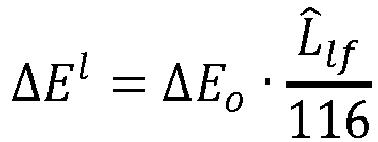
- In a step S44, the wavelet coefficients decoded at step S40 are inverse quantized into wavelet coefficients responsive to the threshold ΔEl of the spatial area of index I to which the wavelet coefficients belong.
Figure 5 depicts a spatial area in the subband LL (grey area) and its corresponding area in the other subbands. All the wavelet coefficients in the grey area are inverse quantized using the same threshold ΔEl . In the following two different embodiments are disclosed.
In a first embodiment, the wavelet coefficients in each subband are first inverse quantized by a quantization step Δb and then de-normalized by the threshold
According to a specific and non-limiting embodiment, the low frequency component(s) L̂lf is(are) decoded from a normative JPEG2000 bitstream. In this case, the first Blf most significant bit planes are allocated for the decoding of these L̂lf values. Consequently, the de-normalization of the wavelet coefficients takes the following form :
In the case where the low frequency component(s) Llf is(are) encoded from metadata, the de-normalization is done without dividing by 2 Blf . When present, the chrominance wavelet coefficients are de-normalized as follows
In a second embodiment, a quantization step size

Then, the wavelet coefficients obtained at step S40 in at least one spatial area I of the low frequency subband LL are inverse quantized by the locally defined quantization step size


- In a step S46, the wavelet coefficients obtained after step S44 are transformed by an inverse wavelet transform into at least one luminance component (L or L̃) and possibly into chrominance components (


- In a step S48, the decoded low frequency component L̂lf is added to the luminance component. In the case of the modified LAB94 perceptual color space, the decoded low frequency component L̂lf is added to Lr which is obtained from L. Optionally, the components L, C1, C2 are then transformed in a non-perceptual color space such as the RGB color space.
- The implementations described herein may be implemented in, for example, a method or a process, an apparatus, a software program, a data stream, or a signal. Even if only discussed in the context of a single form of implementation (for example, discussed only as a method or a device), the implementation of features discussed may also be implemented in other forms (for example a program). An apparatus may be implemented in, for example, appropriate hardware, software, and firmware. The methods may be implemented in, for example, an apparatus such as, for example, a processor, which refers to processing devices in general, including, for example, a computer, a microprocessor, an integrated circuit, or a programmable logic device. Processors also include communication devices, such as, for example, computers, cell phones, portable/personal digital assistants ("PDAs"), and other devices that facilitate communication of information between end-users.
- Implementations of the various processes and features described herein may be embodied in a variety of different equipment or applications, particularly, for example, equipment or applications. Examples of such equipment include an encoder, a decoder, a post-processor processing output from a decoder, a pre-processor providing input to an encoder, a video coder, a video decoder, a video codec, a web server, a set-top box, a laptop, a personal computer, a cell phone, a PDA, and other communication devices. As should be clear, the equipment may be mobile and even installed in a mobile vehicle.
- Additionally, the methods may be implemented by instructions being performed by a processor, and such instructions (and/or data values produced by an implementation) may be stored on a processor-readable medium such as, for example, an integrated circuit, a software carrier or other storage device such as, for example, a hard disk, a compact diskette ("CD"), an optical disc (such as, for example, a DVD, often referred to as a digital versatile disc or a digital video disc), a random access memory ("RAM"), or a read-only memory ("ROM"). The instructions may form an application program tangibly embodied on a processor-readable medium. Instructions may be, for example, in hardware, firmware, software, or a combination. Instructions may be found in, for example, an operating system, a separate application, or a combination of the two. A processor may be characterized, therefore, as, for example, both a device configured to carry out a process and a device that includes a processor-readable medium (such as a storage device) having instructions for carrying out a process. Further, a processor-readable medium may store, in addition to or in lieu of instructions, data values produced by an implementation.
- As will be evident to one of skill in the art, implementations may produce a variety of signals formatted to carry information that may be, for example, stored or transmitted. The information may include, for example, instructions for performing a method, or data produced by one of the described implementations. For example, a signal may be formatted to carry as data the rules for writing or reading the syntax of a described embodiment, or to carry as data the actual syntax-values written by a described embodiment. Such a signal may be formatted, for example, as an electromagnetic wave (for example, using a radio frequency portion of spectrum) or as a baseband signal. The formatting may include, for example, encoding a data stream and modulating a carrier with the encoded data stream. The information that the signal carries may be, for example, analog or digital information. The signal may be transmitted over a variety of different wired or wireless links, as is known. The signal may be stored on a processor-readable medium.
- A number of implementations have been described. Nevertheless, it will be understood that various modifications may be made. For example, elements of different implementations may be combined, supplemented, modified, or removed to produce other implementations. Additionally, one of ordinary skill will understand that other structures and processes may be substituted for those disclosed and the resulting implementations will perform at least substantially the same function(s), in at least substantially the same way(s), to achieve at least substantially the same result(s) as the implementations disclosed. Accordingly, these and other implementations are contemplated by this application.
- This encoding/decoding method are particularly advantageous for visually-lossless encoding of HDR content and may be used in Digital cinema.
According to exemplary and non-limitative embodiments, the
Claims (16)
- A method for encoding an image represented in a perceptual color space, wherein the image has at least a luminance component, the method comprising:- transforming (20) by a wavelet transform the luminance component to form at least one low frequency subband of wavelet coefficients;- determining (22, 222) a low frequency component from the wavelet coefficient(s) of at least one spatial area of the low frequency subband;- quantizing and inverse quantizing (22, 224) said determined low frequency component to obtain a reconstructed low frequency component L̂lf for the at least one spatial area;- subtracting (24) the reconstructed low frequency component from the wavelet coefficients of the spatial area;- quantizing (26, 28) the wavelet coefficients in the spatial area responsive to a threshold, wherein said threshold is proportional to the reconstructed low frequency component L̂lf ; and- encoding (30) the quantized wavelet coefficients and the low frequency component.
- The method of claim 1, wherein the spatial area comprises a single wavelet coefficient and wherein reconstructing a low frequency component for the spatial area of the low frequency subband comprises quantizing and inverse quantizing the single wavelet coefficient.
- The method of claim 1, wherein the spatial area comprises at least two wavelet coefficients and wherein reconstructing a low frequency component for the spatial area of the low frequency subband comprises averaging the at least two wavelet coefficients into an averaged coefficient, quantizing and inverse quantizing the average coefficient.
- The method according to any of claims 1 to 3, wherein quantizing the wavelet coefficients of the spatial area comprises:- normalizing the wavelet coefficients using the threshold of the spatial area; and- quantizing the normalized wavelet coefficients using a quantization step size independent of the spatial area.
- The method according to claim 3, wherein quantizing the wavelet coefficients in the spatial area comprises:- determining a quantization step size for the spatial area from the threshold of the spatial area; and- quantizing the wavelet coefficients using the determined quantization step size.
- The method according to any of claims 1 to 5, wherein the image has at least one chrominance component and wherein the method further comprises:- transforming by the wavelet transform the at least one chrominance component into chrominance wavelet coefficients; and- normalizing the chrominance wavelet coefficients by the threshold of the spatial area to which the chrominance wavelet coefficients belong.
- The method according to any of claims 1 to 6, wherein the at least one low frequency subband of wavelet coefficients being divided into spatial areas, the method applies on each spatial area.
- A coding device for encoding an image represented in a perceptual color space, the image having at least a luminance component, wherein the coding device comprises :- means for transforming by a wavelet transform the luminance component to form at least one low frequency subband of wavelet coefficients;- means for determining a low frequency component from the wavelet coefficient(s) of at least one spatial area of the low frequency subband;- means for quantizing and inverse quantizing said determined low frequency component to obtain a reconstructed low frequency component L̂lf for the at least one spatial area;- means for subtracting the reconstructed low frequency component from the wavelet coefficients of the spatial area;- means for quantizing the wavelet coefficients in the spatial area responsive to a threshold, wherein said threshold is proportional to the reconstructed low frequency component; and- means for encoding the quantized wavelet coefficients and the low frequency component.
- The coding device according to claim 8, wherein the device is configured to execute the steps of the method for encoding according to any of claims 1 to 7.
- A method for decoding an image having at least a luminance component represented in a perceptual color space, the method comprising:- decoding (40) wavelet coefficients of at least a low frequency subband and a low frequency component for at least one spatial area of the low frequency subband;- inverse quantizing (42, 44) the decoded wavelet coefficients of the spatial area responsive to a threshold, the threshold being proportional to the decoded low frequency component of the spatial area ;- adding (46) the decoded low frequency component to the wavelet coefficients of the spatial area; and- transforming (48) by an inverse wavelet transform the wavelet coefficients to form a reconstructed luminance component.
- The method according to claim 10, wherein inverse quantizing the wavelet coefficients of the spatial area comprises:- inverse quantizing the wavelet coefficients; and- de-normalizing the wavelet coefficients using the threshold of the spatial area.
- The method according to claim 10, wherein inverse quantizing the wavelet coefficients of the spatial area comprises:- determining a quantization step size for the spatial area from the threshold of the spatial area; and- inverse quantizing the wavelet coefficients using the determined quantization step size.
- The method according to any of claims 10 to 12 wherein the image has at least one chrominance component and wherein the method further comprises:- decoding chrominance wavelet coefficients; and- de-normalizing the chrominance wavelet coefficients by the threshold of the spatial area to which the chrominance wavelet coefficients belong.
- The method according to any of claims 10 to 13, wherein the at least one low frequency subband of wavelet coefficients being divided into spatial areas, the method applies on each spatial area.
- A decoding device for decoding an image having at least a luminance component represented in a perceptual color space, wherein the decoding device comprises :- means for decoding wavelet coefficients of at least a low frequency subband and a low frequency component for at least one spatial area of the low frequency subband;- means for inverse quantizing the decoded wavelet coefficients of the spatial area responsive to a threshold, the threshold being proportional to the decoded low frequency component of the spatial area;- means for adding the decoded low frequency component to the wavelet coefficients of the spatial area; and- means for transforming by an inverse wavelet transform the wavelet coefficients to form a reconstructed luminance component.
- A decoding device according to claim 15, wherein the device is configured to execute the steps of the decoding method according to any of claims 10 to 14.
Priority Applications (1)
| Application Number | Priority Date | Filing Date | Title |
|---|---|---|---|
| EP15198213.9A EP3035687A1 (en) | 2014-12-16 | 2015-12-07 | A device and a method for encoding an image and corresponding decoding method and decoding device |
Applications Claiming Priority (3)
| Application Number | Priority Date | Filing Date | Title |
|---|---|---|---|
| EP14307057.1A EP3035686A1 (en) | 2014-12-16 | 2014-12-16 | A device and a method for encoding an image and corresponding decoding method and decoding device |
| EP14307055.5A EP3035685A1 (en) | 2014-12-16 | 2014-12-16 | A device and a method for encoding an image and corresponding decoding method and decoding device |
| EP15198213.9A EP3035687A1 (en) | 2014-12-16 | 2015-12-07 | A device and a method for encoding an image and corresponding decoding method and decoding device |
Publications (1)
| Publication Number | Publication Date |
|---|---|
| EP3035687A1 true EP3035687A1 (en) | 2016-06-22 |
Family
ID=54754561
Family Applications (1)
| Application Number | Title | Priority Date | Filing Date |
|---|---|---|---|
| EP15198213.9A Withdrawn EP3035687A1 (en) | 2014-12-16 | 2015-12-07 | A device and a method for encoding an image and corresponding decoding method and decoding device |
Country Status (2)
| Country | Link |
|---|---|
| US (1) | US9681140B2 (en) |
| EP (1) | EP3035687A1 (en) |
Families Citing this family (8)
| Publication number | Priority date | Publication date | Assignee | Title |
|---|---|---|---|---|
| CN105976824B (en) * | 2012-12-06 | 2021-06-08 | 华为技术有限公司 | Method and device for signal decoding |
| JP6700798B2 (en) * | 2016-01-13 | 2020-05-27 | キヤノン株式会社 | Imaging device and control method thereof |
| US10163029B2 (en) * | 2016-05-20 | 2018-12-25 | Gopro, Inc. | On-camera image processing based on image luminance data |
| WO2019185819A1 (en) * | 2018-03-29 | 2019-10-03 | Fraunhofer-Gesellschaft zur Förderung der angewandten Forschung e.V. | Refined block-based predictive coding and decoding of a picture |
| CN110599406B (en) * | 2019-03-18 | 2022-05-03 | 上海立可芯半导体科技有限公司 | Image enhancement method and device |
| DE102019204527B4 (en) * | 2019-03-29 | 2020-11-19 | Technische Universität München | CODING / DECODING DEVICES AND METHODS FOR CODING / DECODING VIBROTACTILE SIGNALS |
| US12230001B2 (en) * | 2022-01-14 | 2025-02-18 | Fraunhofer-Gesellschaft zur Förderung der angewandten Forschung e.V. | Encoder, decoder and related methods |
| CN119299238B (en) * | 2024-12-12 | 2025-03-18 | 浙江大学 | Network flow anomaly detection method based on online continuous learning |
Citations (2)
| Publication number | Priority date | Publication date | Assignee | Title |
|---|---|---|---|---|
| JP2011004345A (en) * | 2009-06-22 | 2011-01-06 | Nippon Hoso Kyokai <Nhk> | Spatial downsampling processor, spatial upsampling processor, encoding apparatus, decoding apparatus, and program |
| CN102186069A (en) * | 2011-01-14 | 2011-09-14 | 王慧 | Remote sensing image data compression method capable of maintaining measurement performance |
Family Cites Families (3)
| Publication number | Priority date | Publication date | Assignee | Title |
|---|---|---|---|---|
| US8665942B2 (en) * | 2007-01-23 | 2014-03-04 | Sharp Laboratories Of America, Inc. | Methods and systems for inter-layer image prediction signaling |
| EP2887668A1 (en) | 2013-12-19 | 2015-06-24 | Thomson Licensing | Method and device for encoding a high-dynamic range image |
| WO2015128269A1 (en) | 2014-02-26 | 2015-09-03 | Thomson Licensing | Method and device for quantizing image data, method and device for encoding an image and method and device for decoding an image |
-
2015
- 2015-12-07 EP EP15198213.9A patent/EP3035687A1/en not_active Withdrawn
- 2015-12-16 US US14/970,763 patent/US9681140B2/en not_active Expired - Fee Related
Patent Citations (2)
| Publication number | Priority date | Publication date | Assignee | Title |
|---|---|---|---|---|
| JP2011004345A (en) * | 2009-06-22 | 2011-01-06 | Nippon Hoso Kyokai <Nhk> | Spatial downsampling processor, spatial upsampling processor, encoding apparatus, decoding apparatus, and program |
| CN102186069A (en) * | 2011-01-14 | 2011-09-14 | 王慧 | Remote sensing image data compression method capable of maintaining measurement performance |
Non-Patent Citations (6)
| Title |
|---|
| "LogLuv encoding for full gamut, high dynamic range images", JOURNAL OF GRAPHICS TOOLS, 1998 |
| DAVID TOUZÉ ET AL: "HDR Video Coding based on Local LDR Quantization", HDRI2014 -SECOND INTERNATIONAL CONFERENCE AND SME WORKSHOP ON HDR IMAGING, 4 March 2014 (2014-03-04), XP055112158, Retrieved from the Internet <URL:http://people.irisa.fr/Ronan.Boitard/articles/2014/HDR Video Coding based on Local LDR Quantization.pdf> [retrieved on 20140404] * |
| LARSON G W: "LogLuv encoding for full-gamut, high-dynamic range images", JOURNAL OF GRAPHICS TOOLS, ASSOCIATION FOR COMPUTING MACHINERY, NEW YORK, US, vol. 3, no. 1, 22 January 1999 (1999-01-22), pages 15 - 31, XP009133824, ISSN: 1086-7651 * |
| LASSERRE S ET AL: "High Dynamic Range video coding", 16. JCT-VC MEETING; 9-1-2014 - 17-1-2014; SAN JOSE; (JOINT COLLABORATIVE TEAM ON VIDEO CODING OF ISO/IEC JTC1/SC29/WG11 AND ITU-T SG.16 ); URL: HTTP://WFTP3.ITU.INT/AV-ARCH/JCTVC-SITE/,, no. JCTVC-P0159-v3, 15 January 2014 (2014-01-15), XP030115678 * |
| LE LÃ CR ANNEC F ET AL: "Usage of modulation channel for high bit-depth signal encoding", 18. JCT-VC MEETING; 30-6-2014 - 9-7-2014; SAPPORO; (JOINT COLLABORATIVE TEAM ON VIDEO CODING OF ISO/IEC JTC1/SC29/WG11 AND ITU-T SG.16 ); URL: HTTP://WFTP3.ITU.INT/AV-ARCH/JCTVC-SITE/,, no. JCTVC-R0267, 26 June 2014 (2014-06-26), XP030116574 * |
| MANTIUK R ET AL: "Backward compatible high dynamic range MPEG video compression", ACM TRANSACTIONS ON GRAPHICS (TOG), ACM, US, 30 July 2006 (2006-07-30), pages 713 - 723, XP007902456, ISSN: 0730-0301, DOI: 10.1145/1141911.1141946 * |
Also Published As
| Publication number | Publication date |
|---|---|
| US20160173884A1 (en) | 2016-06-16 |
| US9681140B2 (en) | 2017-06-13 |
Similar Documents
| Publication | Publication Date | Title |
|---|---|---|
| US9681140B2 (en) | Device and a method for encoding an image and corresponding decoding method and decoding device | |
| JP2018533860A (en) | Method and apparatus for quantization in video encoding and decoding | |
| US20130177240A1 (en) | Image encoder and image decoder | |
| US20160337668A1 (en) | Method and apparatus for encoding image data and method and apparatus for decoding image data | |
| US9979973B2 (en) | Encoding and decoding methods for adapting the average luminance of high dynamic range pictures and corresponding encoder and decoder | |
| US20170171565A1 (en) | Method and apparatus for predicting image samples for encoding or decoding | |
| EP2890129A1 (en) | Method and device for encoding a high-dynamic range image and/or decoding a bitstream | |
| EP3085088B1 (en) | Method and device for encoding a high-dynamic range image | |
| EP3119088A1 (en) | Method and device for encoding an image, method and device for decoding an image | |
| EP3096520B1 (en) | A method for encoding/decoding a picture block | |
| EP3026908A1 (en) | Method and device for quantizing and de-quantizing a picture using scaling factors for chrominance based on luminance | |
| EP3035685A1 (en) | A device and a method for encoding an image and corresponding decoding method and decoding device | |
| EP3035686A1 (en) | A device and a method for encoding an image and corresponding decoding method and decoding device | |
| US10284879B2 (en) | Image processing apparatus and method based on integerprecision image data | |
| EP3026912A1 (en) | Method and device for encoding and decoding a HDR picture and a LDR picture using illumination information | |
| EP2958327A1 (en) | Method and device for encoding a sequence of pictures | |
| EP3026913A1 (en) | Scalable encoding and decoding methods and corresponding devices with combined intraprediction and interlayer prediction | |
| EP2887665A1 (en) | Method and device for encoding a high-dynamic range image | |
| CN107027027A (en) | Coding, coding/decoding method and the device and the coding/decoding system of image of image | |
| EP2958103A1 (en) | Method and device for encoding a sequence of pictures | |
| EP2887667A1 (en) | Coding of high dynamic range images | |
| WO2015128269A1 (en) | Method and device for quantizing image data, method and device for encoding an image and method and device for decoding an image | |
| EP3146718B1 (en) | Method and device for scalable encoding of a high dynamic range frame and/or decoding a bitstream representing such a frame | |
| US10757427B2 (en) | Method and device for obtaining color difference components for color picture data | |
| WO2015177123A1 (en) | Method and device for encoding a frame and/or decoding a bitstream representing a frame |
Legal Events
| Date | Code | Title | Description |
|---|---|---|---|
| PUAI | Public reference made under article 153(3) epc to a published international application that has entered the european phase |
Free format text: ORIGINAL CODE: 0009012 |
|
| AK | Designated contracting states |
Kind code of ref document: A1 Designated state(s): AL AT BE BG CH CY CZ DE DK EE ES FI FR GB GR HR HU IE IS IT LI LT LU LV MC MK MT NL NO PL PT RO RS SE SI SK SM TR |
|
| AX | Request for extension of the european patent |
Extension state: BA ME |
|
| STAA | Information on the status of an ep patent application or granted ep patent |
Free format text: STATUS: REQUEST FOR EXAMINATION WAS MADE |
|
| 17P | Request for examination filed |
Effective date: 20161208 |
|
| RBV | Designated contracting states (corrected) |
Designated state(s): AL AT BE BG CH CY CZ DE DK EE ES FI FR GB GR HR HU IE IS IT LI LT LU LV MC MK MT NL NO PL PT RO RS SE SI SK SM TR |
|
| STAA | Information on the status of an ep patent application or granted ep patent |
Free format text: STATUS: EXAMINATION IS IN PROGRESS |
|
| 17Q | First examination report despatched |
Effective date: 20171201 |
|
| RAP1 | Party data changed (applicant data changed or rights of an application transferred) |
Owner name: INTERDIGITAL VC HOLDINGS, INC. |
|
| RAP1 | Party data changed (applicant data changed or rights of an application transferred) |
Owner name: INTERDIGITAL VC HOLDINGS, INC. |
|
| GRAP | Despatch of communication of intention to grant a patent |
Free format text: ORIGINAL CODE: EPIDOSNIGR1 |
|
| STAA | Information on the status of an ep patent application or granted ep patent |
Free format text: STATUS: GRANT OF PATENT IS INTENDED |
|
| INTG | Intention to grant announced |
Effective date: 20210119 |
|
| STAA | Information on the status of an ep patent application or granted ep patent |
Free format text: STATUS: THE APPLICATION IS DEEMED TO BE WITHDRAWN |
|
| 18D | Application deemed to be withdrawn |
Effective date: 20210601 |