EP3035466A1 - An installation box having an integrated swivel - Google Patents
An installation box having an integrated swivel Download PDFInfo
- Publication number
- EP3035466A1 EP3035466A1 EP15446507.4A EP15446507A EP3035466A1 EP 3035466 A1 EP3035466 A1 EP 3035466A1 EP 15446507 A EP15446507 A EP 15446507A EP 3035466 A1 EP3035466 A1 EP 3035466A1
- Authority
- EP
- European Patent Office
- Prior art keywords
- swivel
- installation box
- box
- swivels
- locking
- Prior art date
- Legal status (The legal status is an assumption and is not a legal conclusion. Google has not performed a legal analysis and makes no representation as to the accuracy of the status listed.)
- Granted
Links
- 238000009434 installation Methods 0.000 title claims abstract description 66
- 238000010616 electrical installation Methods 0.000 claims abstract description 4
- 125000006850 spacer group Chemical group 0.000 claims description 26
- 230000003993 interaction Effects 0.000 claims 1
- 239000000463 material Substances 0.000 description 2
- 230000001154 acute effect Effects 0.000 description 1
- 230000001419 dependent effect Effects 0.000 description 1
- 238000001746 injection moulding Methods 0.000 description 1
- 230000010354 integration Effects 0.000 description 1
- 238000004519 manufacturing process Methods 0.000 description 1
Images



Classifications
-
- H—ELECTRICITY
- H02—GENERATION; CONVERSION OR DISTRIBUTION OF ELECTRIC POWER
- H02G—INSTALLATION OF ELECTRIC CABLES OR LINES, OR OF COMBINED OPTICAL AND ELECTRIC CABLES OR LINES
- H02G3/00—Installations of electric cables or lines or protective tubing therefor in or on buildings, equivalent structures or vehicles
- H02G3/02—Details
- H02G3/08—Distribution boxes; Connection or junction boxes
- H02G3/12—Distribution boxes; Connection or junction boxes for flush mounting
- H02G3/123—Distribution boxes; Connection or junction boxes for flush mounting in thin walls
Definitions
- the present invention relates to installation boxes for electrical applications and particularly to the mounting of such installation boxes. Particularly, the invention relates to embedded boxes.
- an installation box is shown provided with a mounting device to mount the box in a wall.
- the mounting device comprises a threaded tightening screw on which a clamping lug can be moved up and down along the outer edge of the box so as to, upon rotation of the tightening screw, clamp the box in a hole in a wall plate.
- Such a mounting device requires a plurality of loose and movable parts, which should interact to provide a mounting of the installation box.
- the function may also fail if, for instance, a tilt of the clamping lug makes that the threads of the tightening screw are deformed.
- the object of the invention is to allow a simple and fast mountable and thereby more cost-effective installation box by the fact that it does not comprise any retrofit parts.
- the object of the invention is also that the installation box according to the invention should be possible to be integrally manufactured.
- the object of the invention is further to present such an installation box that allows the installation of the box in boards of defined thicknesses.
- the object of the invention is to also present such an installation box that allows the installation of the box optionally in one of two boards each of which having a defined thickness.
- the invention concerns an installation box intended for electrical installations.
- the box comprises at least one side wall the upper edge of which is provided with a bearing fold.
- the side wall may be a wall in a single box as well as a double box.
- the side wall is provided with mounting columns, to which the electrical inserts are attached by screws.
- the side wall is further provided with lead-throughs for the electrical cables to the box.
- the bottom of the box is connected to the lower portion of the side wall.
- the box is provided with at least two swivels which individually are provided with a bearing end and an operating end. Each swivel is integrated with the side wall of the box by a first pivot on which the swivel is rotatable at least between a mounting position and a locking position.
- the integration consists of box, swivel, and pivot being integrally formed as a unit, preferably by injection moulding.
- the pivot is placed at a distance from said two ends of the swivel so that the swivel performs as a lever around said pivot.
- the pivot is oriented parallel to the upper edge of the side wall.
- each swivel is provided with a locking device for the locking up of the respective swivel in a bearing position wherein the bearing end of the swivel is directed principally 90° outward from said side wall. In this position, the bearing end upon mounted box is pressed against the inner surface of a mounting board, which preferably is an inner surface of a wall board.
- the locking device comprises a first lock means interacting with at least the operating end of the first swivel and, by means of a snap-in function, arranged to interact for the locking of the swivel in said bearing position.
- the second lock means may be defined as the operating end of the swivel adapted to the first lock means.
- the lock means may appear in various ways, which will be clear from the embodiments described in the detailed description.
- the second lock means is placed on the operating end of the second swivel.
- the first lock means on the operating end of the first swivel comprises two elastic projections, which are stretchable to be inserted under a respective lock edge of said first lock means.
- the second lock means is placed in said bottom and is provided with at least one snap edge formed to interact with the first lock means of each swivel.
- the second lock means is a part of the bottom of the installation box.
- the second lock means is formed with a plurality of snap edges oriented in the direction of travel of the respective swivel so that the operating end of a swivel can be locked in several steps.
- the snap edges are integrated with the bottom of the box.
- the snap edges of the second lock means are oriented in a stepped way in the bottom of the box. This means that the box can be clamped differently tightly in the mounting board by pressing the operating end of the swivel differently far down toward the bottom of the box upon the mounting.
- the respective operating end of the swivels is located flush with the bottom of the box and interacts with the remaining bottom of the box into a whole bottom when the swivels are situated in the locking position.
- the swivel ends are a part of the bottom of the box.
- the portion of the respective operating end of the swivels that is situated closest to said pivot is located flush with the side wall of the box and interacts with the remaining side wall of the box into an entire side wall when the swivels are situated in the locking position.
- the swivel ends are a part of the wall of the box.
- the swivel ends are a part of both the bottom and side wall of the box.
- the respective bearing end of the swivels is provided with a mounting spacer.
- This mounting spacer means a possibility of using the same box for, on one hand, a thin mounting plate, for instance with a thickness in the interval of 10-14 mm, and on the other hand for a thick mounting plate, for instance with a thickness in the interval of 23-27 mm.
- the mounting spacer is integrated with the swivel by a second pivot on which the mounting spacer is rotatable between a depth position and a shallow position.
- the depth position means that the mounting spacer is inactive, the box being mounted in a thick mounting plate while the shallow position means that the mounting spacer is active and the box is mounted in a thin mounting plate.
- said second pivot is parallel to said first pivot. This embodiment means that the rotations of both the swivel and the mounting spacer into a respective active position are made in the same direction and around parallel axes.
- the mounting spacer can be attached by snap action in the shallow position.
- the mounting spacer is, in this connection, provided with a protuberance having an edge, which is snapped down into a groove in the bearing end of the swivel situated near the first pivot.
- the second pivot is situated at the outermost edge of the bearing end.
- thermal shielding light mounting and LED installations in walls or ceilings are thermal shielding light mounting and LED installations in walls or ceilings.
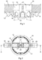
- Figure 1 shows a first embodiment of an installation box 10 for electrical installations, preferably mounted in a hole in a wall board W.
- the installation box 10 is provided with at least one side wall 11 the upper edge of which is provided with a bearing fold 12.
- the installation box is further provided with a bottom 13 connected to the lower edge 14 of the side wall 11.
- the installation box 10 is provided with at least two swivels 15, which individually are provided with a bearing end 16 and an operating end 17.
- each swivel is provided a mounting spacer 18.
- Figure 1 shows the swivels in a locking position and a mounting position marked with dashed lines.
- the operating ends 17 of the swivels 15, which are marked in the figure, originate from the mounting position, i.e., the rotated position in the figure wherein the mounting spacers 18 of the swivels are marked with dashed lines.
- FIG. 2 shows the installation box 10 from above with its bearing fold 12 and its bottom 13.
- the figure also shows the two swivels 15 mounted opposite each other in the wall of the installation box with the respective bearing end 16 and operating end 17 of the swivels.
- the outer edge of the bearing end 16 of each swivel 15 is provided with the mounting spacers 18.
- the two operating ends 17 are lowered in the position shown so that they are located flush with the bottom 13 of the box and are in this locking position arrested in the bottom 13 of the box by snap action between a first lock means 21 on the operating end 17 of at least one of the swivels 15 and a second lock means 22, which is an integrated and fixedly connected part of the bottom 13 of the box.
- Said lock means constitute together the locking device of the swivels, which provides a locking of the swivels in the locking position shown both in Figure 1 and in Figure 2 .
- the mounting of the installation box 10 according to Figure 1 has been made by the swivels 15 having been located in their mounting positions according to the dashed lines, wherein the box 10 has been inserted through the hole of the wall board W after which the operating ends 17 of the swivels 15 have been brought against each other and pressed down to the bottom 13 of the box and there been snapped-in against the second lock means 22.
- the bearing ends 16 of the swivels 15 have, upon this lever movement, been jammed against the inner surface of the wall board W, wherein the box is secured in the hole of the wall board W.
- FIG 3 shows a section through the installation box 10 with the respective swivel 15 in its locking position.
- Each swivel 15 is integrated with the side wall 11 of the box by a first pivot 31, each swivel 15 being rotatable at least between a mounting position in which the operating ends 17 of the swivels 15 are directed out through the opening of the box according to the position in Figure 1 and a locking position according to Figure 3 , the pivot 31 being placed at a distance from said two ends 16, 17 of the swivels 15 so that each swivel works as a lever upon rotation around the respective first pivot 31.
- each one of the swivels 15 of the embodiment shown is provided with mounting spacers 18 each one connected with the bearing end 16 of the respective swivel 15 via a second pivot 32.
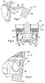
- Figure 4 shows the operating end 171 of the first swivel 151 snapped in place in a normal locking position in a locking device 40 while the operating end 172 of the second swivel 152 is shown snapped in place in a pressing position in the locking device 40.
- the bearing end 16 of the swivel 151 is directed principally 90° outward from the side wall 11 of the box 10.
- the bearing end 16 of the swivel 152 has been further rotated around the first pivot 31 and forms an angle ⁇ in relation to the side wall of the box 10 that is smaller than 90°, i.e., forms an acute angle ⁇ with the side wall 11.
- the angle ⁇ 80°.
- FIG 5 shows in enlargement the locking device 40 for the swivels 151, 152 of the installation box 10 in a position that corresponds to Figure 3 wherein both swivels 15 are shown in the normal locking position.
- the locking device 40 aims at locking the swivels in relation to the installation box 10 and consists of a first lock means 51 having a first outwardly leaning and toothed side and a second lock means 52 having a second outwardly leaning and toothed side. These two leaning sides are formed with said lock means 51, 52 in the form of teeth, which, in the embodiment illustrated, are three in number on each side.
- the number of teeth on each side of the locking device 40 may be from 1 to 4.
- the sides are centrally placed in the bottom 13 of the box 10 at an angle of inclination of ⁇ in relation to the bottom 13 of the box 10.
- the angle of inclination ⁇ is 110° ⁇ ⁇ ⁇ 130°, preferably 120°.
- These leaning sides 51, 52 of the locking device aim at locking the swivels in a pressing position.
- Figure 5 shows the two operating ends 171, 172 of the swivels locked in a normal locking position, the operating end 171 of the first swivel 151 being snapped in place under a first ratchet member 53 while the operating end 172 of the second swivel 152 being snapped in place under a second ratchet member 54.
- These two ratchet members are a part of the locking device and are centrally placed in the upper portion of the locking device.
- These two ratchet members 53, 54 are arranged to arrest the swivels 151, 152 in said normal locking position.
- Figure 6 shows in enlargement the locking device 40 for the installation box 10 in a position that corresponds to Figure 4 wherein the first swivel 151 is locked in a normal position under the first ratchet member 53 while the operating end 172 of the second swivel 152 is locked in a pressing position under the lowermost tooth of the side of the lock means 52.
- Figure 7 shows the second swivel 152 in a section of a partial enlargement from Figure 3 wherein the swivel is connected to the side wall 11 via the first pivot 31.
- the first pivot is essentially parallel to the side wall 11.
- the figure shows the bearing end 16 to which a mounting spacer 18 is connected via the second pivot 32.
- the mounting spacer 18 is provided with a hooked lock protuberance 71, which can be locked in a lock slot 72 when the mounting spacer 18 is rotated around the second pivot 32, i.e., counter-clockwise in the figure toward the side wall 11.
- the mounting spacer may, in this connection, be used by being activated by the rotation and locking of the lock protuberance 71 in the lock slot 72 or being inactive in the position shown in the figure depending on the thickness of the wall board.
- FIG 8 shows a section through the installation box 10 with the swivels 151, 152 in the mounting position. In this position, each swivel is rotated so that the respective operating end 17 thereof extends up through the opening 80 of the box, wherein the installation box with the swivels can be installed in the opening of a wall board.
- the position shown of the swivels in the figure corresponds to the dashed position of the swivels in Figure 1 .
- the mounting spacers 18 are in this position inserted toward the centre of the box in the swivel openings 81, 82, which are formed in the bottom and side wall of the box for the swivels and the mounting spacers thereof to be rotatable maximally around the pivots 31.
- the mounting ends of the swivels are L-shaped so that they should be able to close the holes in the box by coinciding with both the side wall of the box and the bottom of the box when they have been rotated to the pressing positions thereof shown in Figure 2 .
- Figure 9 shows an enlargement from Figure 8 showing the swivel 152 in the mounting position, the first pivot 31 forming a right angle with the side wall 11 of the box 10, the bearing end 16 of the swivel being essentially parallel to the side wall 11 of the box.
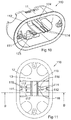
- Figure 10 shows a mounting box 110 according to a second embodiment of the invention in a mounting position.
- the box is provided with a first swivel 111 and a second swivel 112, both of which are rotatably connected and integrated with the side wall 11 of the box.
- the first swivel 111 is provided with an operating end 173 intended to interlockably interact with the second swivel 112, which also is provided with an operating end 174, which is provided with elastic locking springs 114, projecting from the end in parallel and principally equally far, which upon a locking of the swivel 112 either may be pressed toward each other or be stretched from each other so as to, in doing so, interact with the first swivel 111.
- Figure 11 shows the mounting box 110 from above with its bearing fold 12 and its bottom 13.
- the locking springs 114 of the second swivel 112 are arranged to interact with locking shackles 115 placed on the first swivel 111, which two locking elements 114, 115 upon the locking of the second swivel 112 against the first swivel 111 are rotated into a normal locking position.
- the locking springs 114 are provided with a respective sliding pin 116 directed toward each other, which slide outside over the locking shackles 115 into locking under locking hooks 117 connected to the locking shackles 115. In this embodiment, only one locking position exists.
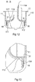
- Figure 12 shows a section B-B from Figure 11 , the first swivel 111 and second swivel 112 of the mounting box 110 being shown in their respective mounting positions. Both swivels are connected integratedly to the side wall 11 via a respective first pivot 31 around which the respective swivel is rotatable between a mounting position according to the figure and a normal locking position.
- the figure shows the first swivel 111 with the locking shackles 115 of one side and its locking hook 117.
- the figure also shows the second swivel 112 with the elastic locking spring 114 of one side.
- Each swivel 111, 112 is provided with a bearing end 16 arranged to, in a normal locking position, be folded out and pressed against the bearing fold 12 around a wall board like what has previously been shown in the embodiment according to Figure 1 .
- Figure 13 shows in enlargement from Figure 12 the second swivel 112 connected to the side wall 11 of the box via the first pivot 31.
- the bearing end 16 is provided with a mounting spacer 131 in the form of a shim of suitable thickness, which is selected with regard to the thickness of the wall board.
- the opposite side of the box is formed in the same way with regard to said pivot 31
- Figure 14 shows the installation box 110 according to Figure 10 in a locking position viz. in its normal locking position wherein the first swivel 111 is rotated downward around its first pivot 31 to a position wherein the locking hooks 117 are oriented essentially parallel to the bottom 13 of the box.
- the second swivel 112 may be rotated downward around its first pivot and by its locking springs 114 be snapped outside over the locking hooks 117 into an interlocking of the two swivels 111, 112.
- the invention also comprises embodiments wherein the locking springs are squeezed together and snap on the inside of locking hooks directed toward each other.
- the two swivels constitute parts of the bottom 13 and side walls 11 of the installation box so that the box becomes whole, wherein screws, washers, and the like cannot fall through openings, slots, and grooves in the box.
- the bearing end 16 of the second swivel 112 is shown in the normal locking position, the bearing end 16 being directed essentially 90° outward from the side wall 11 of the box.
- Figure 14 also shows that the bearing end 16 is provided with a knurled mounting spacer 131.
- Figure 15 shows the installation box 110 according to Figure 14 from above with the first swivel 111 and the second swivel 112 lowered and connected into a normal locking position wherein the bearing end 161 of the first swivel 111 extends perpendicularly outward from the side wall of the box and wherein the bearing end 162 of the second swivel 112 extends perpendicularly outward from the side wall of the box in the opposite direction.
- the operating end 173 of the first swivel 111 and the operating end 174 of the second swivel 112 exhibit a locking device 40, which aims at locking the swivels 111, 112 in relation to the installation box 110.
- the locking springs 114 of the second swivel 112 have in the figure been snapped over the locking hooks 117 of the first swivel 111 into an interlocking of the swivels and thereby a locking of their movement in relation to the installation box 110.
- the second swivel 112 has closed the opening 118, see Figure 11 , in such a way that the swivel 112 is located flush with the bottom 13 of the installation box in this normal locking position.
- Figure 16 shows the section C-C from Figure 15 wherein it is seen that the operating end 174 of the second swivel 112 overlaps the operating end 173 of the first swivel on the inside of the installation box 110. Furthermore, it is seen in the figure that the two swivels 111, 112 are formed in the same piece of material as the rest of the installation box 110 and are connected/integrated with the side walls 11 of the box by the first pivot 31.
- Figure 17 shows an enlargement of a portion of the installation box 110 from Figure 16 wherein the second swivel 112 is connected to the side wall 11 via the first pivot 31.
- the swivel 112 in Figure 17 is maximally rotated around the pivot 31, the swivel pivot 31 having been flexed 90° in relation to the side wall 11 so that the swivel portion 176 closest to the pivot 31 is principally parallel to the side wall 11.
- the pivot according to this shown embodiment may, within the scope of the invention, be formed so that the flexing may exceed 90°, wherein a further pressing of the bearing end 16 and possibly the mounting spacer 131 can be accomplished against a wall board.
- a further pressing implies a further developed locking device between the swivels, which allows such a further pressing in a locked position.
- the opposite side of the box is formed in the same way with regard to said pivot 31.
Landscapes
- Engineering & Computer Science (AREA)
- Architecture (AREA)
- Civil Engineering (AREA)
- Structural Engineering (AREA)
- Casings For Electric Apparatus (AREA)
Abstract
Description
- The present invention relates to installation boxes for electrical applications and particularly to the mounting of such installation boxes. Particularly, the invention relates to embedded boxes.
- In, for instance, the document
EP 1775815 with, among others, Legrand France as applicant, an installation box is shown provided with a mounting device to mount the box in a wall. The mounting device comprises a threaded tightening screw on which a clamping lug can be moved up and down along the outer edge of the box so as to, upon rotation of the tightening screw, clamp the box in a hole in a wall plate. By the fact that the clamping lug can be screwed down into an inserted lower position, the box can be inserted into the hole and by manoeuvring the tightening screw, the clamping lug can be displaced along the outside of the box and in doing so be clamped against the inside of the wall plate. - Such a mounting device requires a plurality of loose and movable parts, which should interact to provide a mounting of the installation box.
- The manufacturing cost of such an installation box increases with regard to how many retrofit loose parts being required for the box. In
EP 1775815 , two extra retrofit movable parts are present, viz. the clamping lug and the tightening screw, the tightening screw of which in addition should be movable in a pendulum movement to allow a retracted position for the clamping lug. - By the mounting device comprising a thread, the function may also fail if, for instance, a tilt of the clamping lug makes that the threads of the tightening screw are deformed.
- Similar mounting devices for installation boxes are also seen in the documents
DE 7524603U andDE 19922212 , which mounting devices also require retrofit loose and movable parts for the mounting function of the box. - The object of the invention is to allow a simple and fast mountable and thereby more cost-effective installation box by the fact that it does not comprise any retrofit parts.
- The object of the invention is also that the installation box according to the invention should be possible to be integrally manufactured.
- The object of the invention is further to present such an installation box that allows the installation of the box in boards of defined thicknesses.
- In addition, the object of the invention is to also present such an installation box that allows the installation of the box optionally in one of two boards each of which having a defined thickness.
- By the present invention, as the same appears in the independent claims, the above-mentioned objects are met wherein said disadvantages have been eliminated. Suitable embodiments of the invention are defined in the dependent claims.
- The invention concerns an installation box intended for electrical installations. The box comprises at least one side wall the upper edge of which is provided with a bearing fold. The side wall may be a wall in a single box as well as a double box. The side wall is provided with mounting columns, to which the electrical inserts are attached by screws. The side wall is further provided with lead-throughs for the electrical cables to the box. The bottom of the box is connected to the lower portion of the side wall. The box is provided with at least two swivels which individually are provided with a bearing end and an operating end. Each swivel is integrated with the side wall of the box by a first pivot on which the swivel is rotatable at least between a mounting position and a locking position. The integration consists of box, swivel, and pivot being integrally formed as a unit, preferably by injection moulding. The pivot is placed at a distance from said two ends of the swivel so that the swivel performs as a lever around said pivot. The pivot is oriented parallel to the upper edge of the side wall. The advantages of the invention are that the entire installation box can be integrally injection-moulded.
- In one embodiment of the invention, each swivel is provided with a locking device for the locking up of the respective swivel in a bearing position wherein the bearing end of the swivel is directed principally 90° outward from said side wall. In this position, the bearing end upon mounted box is pressed against the inner surface of a mounting board, which preferably is an inner surface of a wall board.
- In one embodiment of the invention, the locking device comprises a first lock means interacting with at least the operating end of the first swivel and, by means of a snap-in function, arranged to interact for the locking of the swivel in said bearing position. In this embodiment, the second lock means may be defined as the operating end of the swivel adapted to the first lock means. Within the scope of the invention, the lock means may appear in various ways, which will be clear from the embodiments described in the detailed description.
- In one embodiment of the invention, the second lock means is placed on the operating end of the second swivel.
- In one embodiment of the invention, the first lock means on the operating end of the first swivel comprises two elastic projections, which are stretchable to be inserted under a respective lock edge of said first lock means.
- In one embodiment of the invention, the second lock means is placed in said bottom and is provided with at least one snap edge formed to interact with the first lock means of each swivel. Thus, in this embodiment, the second lock means is a part of the bottom of the installation box.
- In one embodiment of the invention, the second lock means is formed with a plurality of snap edges oriented in the direction of travel of the respective swivel so that the operating end of a swivel can be locked in several steps. Also in this embodiment, the snap edges are integrated with the bottom of the box.
- In one embodiment of the invention, the snap edges of the second lock means are oriented in a stepped way in the bottom of the box. This means that the box can be clamped differently tightly in the mounting board by pressing the operating end of the swivel differently far down toward the bottom of the box upon the mounting.
- In one embodiment of the invention, the respective operating end of the swivels is located flush with the bottom of the box and interacts with the remaining bottom of the box into a whole bottom when the swivels are situated in the locking position. Thus, the swivel ends are a part of the bottom of the box.
- In one embodiment of the invention, the portion of the respective operating end of the swivels that is situated closest to said pivot is located flush with the side wall of the box and interacts with the remaining side wall of the box into an entire side wall when the swivels are situated in the locking position. Correspondingly, the swivel ends are a part of the wall of the box.
- In a combination of these two embodiments, the swivel ends are a part of both the bottom and side wall of the box.
- In one embodiment of the invention, the respective bearing end of the swivels is provided with a mounting spacer. This mounting spacer means a possibility of using the same box for, on one hand, a thin mounting plate, for instance with a thickness in the interval of 10-14 mm, and on the other hand for a thick mounting plate, for instance with a thickness in the interval of 23-27 mm.
- In one embodiment of the invention, the mounting spacer is integrated with the swivel by a second pivot on which the mounting spacer is rotatable between a depth position and a shallow position. The depth position means that the mounting spacer is inactive, the box being mounted in a thick mounting plate while the shallow position means that the mounting spacer is active and the box is mounted in a thin mounting plate.
- In one embodiment of the invention, said second pivot is parallel to said first pivot. This embodiment means that the rotations of both the swivel and the mounting spacer into a respective active position are made in the same direction and around parallel axes.
- In one embodiment of the invention, the mounting spacer can be attached by snap action in the shallow position. The mounting spacer is, in this connection, provided with a protuberance having an edge, which is snapped down into a groove in the bearing end of the swivel situated near the first pivot. In this connection, the second pivot is situated at the outermost edge of the bearing end.
- Further fields of application for the invention are thermal shielding light mounting and LED installations in walls or ceilings.
- Now, the invention will be described in more detail, references being made in connection with the accompanying drawing figures.
- Figure 1
- shows a side view of an installation box according to a first embodiment of the invention with swivels in both a locking position and a dashed mounting position.
- Figure 2
- shows the installation box in
Figure 1 from above. - Figure 3
- shows a section A-A through the installation box according to
Figure 2 with the operating ends of the swivels in a first lock-up position. - Figure 4
- shows a section through the installation box according to
Figure 1 with one of the swivels in a first locking position and the second swivel in an alternative locking position. - Figure 5
- shows a partial enlargement from
Figure 3 . - Figure 6
- shows a partial enlargement from
Figure 4 . - Figure 7
- shows a further partial enlargement from
Figure 3 . - Figure 8
- shows a section through the installation box in
Figure 1 with the swivels in the mounting position. - Figure 9
- shows an enlargement from
Figure 8 . - Figure 10
- shows a perspective view of an installation box according to a second embodiment according to the invention in a mounting position.
- Figure 11
- shows a top view of the installation box according to
Figure 10 . - Figure 12
- shows a cross-section from
Figure 11 . - Figure 13
- shows an enlargement from
Figure 12 . - Figure 14
- shows a perspective view of the installation box according to
Figure 10 in a locking position. - Figure 15
- shows a top view of the installation box according to
Figure 14 . - Figure 16
- shows a cross-section from
Figure 15 . - Figure 17
- shows an enlargement from
Figure 16 . - In the section views according to
Figures 3-9 , section indications have been made for the most relevant parts in order not to make the figures indistinct. -
Figure 1 shows a first embodiment of aninstallation box 10 for electrical installations, preferably mounted in a hole in a wall board W. Theinstallation box 10 is provided with at least oneside wall 11 the upper edge of which is provided with a bearingfold 12. The installation box is further provided with a bottom 13 connected to thelower edge 14 of theside wall 11. Furthermore, theinstallation box 10 is provided with at least twoswivels 15, which individually are provided with abearing end 16 and an operatingend 17. In the embodiment illustrated, each swivel is provided a mountingspacer 18. It should be emphasized thatFigure 1 shows the swivels in a locking position and a mounting position marked with dashed lines. The operating ends 17 of theswivels 15, which are marked in the figure, originate from the mounting position, i.e., the rotated position in the figure wherein the mountingspacers 18 of the swivels are marked with dashed lines. -
Figure 2 shows theinstallation box 10 from above with itsbearing fold 12 and its bottom 13. The figure also shows the twoswivels 15 mounted opposite each other in the wall of the installation box with the respective bearing end 16 and operatingend 17 of the swivels. The outer edge of thebearing end 16 of eachswivel 15 is provided with the mountingspacers 18. The two operating ends 17 are lowered in the position shown so that they are located flush with the bottom 13 of the box and are in this locking position arrested in the bottom 13 of the box by snap action between a first lock means 21 on the operatingend 17 of at least one of theswivels 15 and a second lock means 22, which is an integrated and fixedly connected part of the bottom 13 of the box. Said lock means constitute together the locking device of the swivels, which provides a locking of the swivels in the locking position shown both inFigure 1 and inFigure 2 . - The mounting of the
installation box 10 according toFigure 1 has been made by theswivels 15 having been located in their mounting positions according to the dashed lines, wherein thebox 10 has been inserted through the hole of the wall board W after which the operating ends 17 of theswivels 15 have been brought against each other and pressed down to the bottom 13 of the box and there been snapped-in against the second lock means 22. Thus, the bearing ends 16 of theswivels 15 have, upon this lever movement, been jammed against the inner surface of the wall board W, wherein the box is secured in the hole of the wall board W. - The parts shown of the
installation box 10 inFigures 1-2 are compression-moulded in just one moment and constitute, in doing so, continuous pieces of material. -
Figure 3 shows a section through theinstallation box 10 with therespective swivel 15 in its locking position. Eachswivel 15 is integrated with theside wall 11 of the box by afirst pivot 31, eachswivel 15 being rotatable at least between a mounting position in which the operating ends 17 of theswivels 15 are directed out through the opening of the box according to the position inFigure 1 and a locking position according toFigure 3 , thepivot 31 being placed at a distance from said two ends 16, 17 of theswivels 15 so that each swivel works as a lever upon rotation around the respectivefirst pivot 31. The figure also shows that each one of theswivels 15 of the embodiment shown is provided with mountingspacers 18 each one connected with thebearing end 16 of therespective swivel 15 via asecond pivot 32. -
Figure 4 shows the operatingend 171 of thefirst swivel 151 snapped in place in a normal locking position in alocking device 40 while the operatingend 172 of thesecond swivel 152 is shown snapped in place in a pressing position in thelocking device 40. In the normal locking position, the bearingend 16 of theswivel 151 is directed principally 90° outward from theside wall 11 of thebox 10. In the pressing position, the bearingend 16 of theswivel 152 has been further rotated around thefirst pivot 31 and forms an angle α in relation to the side wall of thebox 10 that is smaller than 90°, i.e., forms an acute angle α with theside wall 11. Preferably, 45° < α < 90°. InFigure 4 , the angle α = 80°. -
Figure 5 shows in enlargement thelocking device 40 for theswivels installation box 10 in a position that corresponds toFigure 3 wherein bothswivels 15 are shown in the normal locking position. The lockingdevice 40 aims at locking the swivels in relation to theinstallation box 10 and consists of a first lock means 51 having a first outwardly leaning and toothed side and a second lock means 52 having a second outwardly leaning and toothed side. These two leaning sides are formed with said lock means 51, 52 in the form of teeth, which, in the embodiment illustrated, are three in number on each side. The number of teeth on each side of thelocking device 40 may be from 1 to 4. The sides are centrally placed in the bottom 13 of thebox 10 at an angle of inclination of β in relation to the bottom 13 of thebox 10. The angle of inclination β is 110° < β < 130°, preferably 120°. These leaningsides Figure 5 shows the two operating ends 171, 172 of the swivels locked in a normal locking position, the operatingend 171 of thefirst swivel 151 being snapped in place under afirst ratchet member 53 while the operatingend 172 of thesecond swivel 152 being snapped in place under asecond ratchet member 54. These two ratchet members are a part of the locking device and are centrally placed in the upper portion of the locking device. - These two
ratchet members swivels -
Figure 6 shows in enlargement thelocking device 40 for theinstallation box 10 in a position that corresponds toFigure 4 wherein thefirst swivel 151 is locked in a normal position under thefirst ratchet member 53 while the operatingend 172 of thesecond swivel 152 is locked in a pressing position under the lowermost tooth of the side of the lock means 52. -
Figure 7 shows thesecond swivel 152 in a section of a partial enlargement fromFigure 3 wherein the swivel is connected to theside wall 11 via thefirst pivot 31. The first pivot is essentially parallel to theside wall 11. The figure shows thebearing end 16 to which a mountingspacer 18 is connected via thesecond pivot 32. The mountingspacer 18 is provided with ahooked lock protuberance 71, which can be locked in alock slot 72 when the mountingspacer 18 is rotated around thesecond pivot 32, i.e., counter-clockwise in the figure toward theside wall 11. The mounting spacer may, in this connection, be used by being activated by the rotation and locking of thelock protuberance 71 in thelock slot 72 or being inactive in the position shown in the figure depending on the thickness of the wall board. -
Figure 8 shows a section through theinstallation box 10 with theswivels opening 80 of the box, wherein the installation box with the swivels can be installed in the opening of a wall board. The position shown of the swivels in the figure corresponds to the dashed position of the swivels inFigure 1 . The mountingspacers 18 are in this position inserted toward the centre of the box in theswivel openings pivots 31. As is seen in the figure, the mounting ends of the swivels are L-shaped so that they should be able to close the holes in the box by coinciding with both the side wall of the box and the bottom of the box when they have been rotated to the pressing positions thereof shown inFigure 2 . -
Figure 9 shows an enlargement fromFigure 8 showing theswivel 152 in the mounting position, thefirst pivot 31 forming a right angle with theside wall 11 of thebox 10, the bearingend 16 of the swivel being essentially parallel to theside wall 11 of the box. -
Figure 10 shows a mountingbox 110 according to a second embodiment of the invention in a mounting position. The box is provided with afirst swivel 111 and asecond swivel 112, both of which are rotatably connected and integrated with theside wall 11 of the box. Thefirst swivel 111 is provided with an operatingend 173 intended to interlockably interact with thesecond swivel 112, which also is provided with an operatingend 174, which is provided with elastic locking springs 114, projecting from the end in parallel and principally equally far, which upon a locking of theswivel 112 either may be pressed toward each other or be stretched from each other so as to, in doing so, interact with thefirst swivel 111. -
Figure 11 shows the mountingbox 110 from above with itsbearing fold 12 and its bottom 13. The locking springs 114 of thesecond swivel 112 are arranged to interact with lockingshackles 115 placed on thefirst swivel 111, which two lockingelements second swivel 112 against thefirst swivel 111 are rotated into a normal locking position. In this shown embodiment, the locking springs 114 are provided with a respective slidingpin 116 directed toward each other, which slide outside over the lockingshackles 115 into locking under lockinghooks 117 connected to thelocking shackles 115. In this embodiment, only one locking position exists. When the box is in its mounting position according to the figure, its bottom 13 exhibits anopening 118 across the entire box. In the normal locking position, theswivels opening 118 is closed by the swivels and the box obtains an almost flat bottom 13 with the exception of said lockingelements -
Figure 12 shows a section B-B fromFigure 11 , thefirst swivel 111 andsecond swivel 112 of the mountingbox 110 being shown in their respective mounting positions. Both swivels are connected integratedly to theside wall 11 via a respectivefirst pivot 31 around which the respective swivel is rotatable between a mounting position according to the figure and a normal locking position. The figure shows thefirst swivel 111 with the lockingshackles 115 of one side and itslocking hook 117. The figure also shows thesecond swivel 112 with theelastic locking spring 114 of one side. Eachswivel bearing end 16 arranged to, in a normal locking position, be folded out and pressed against the bearingfold 12 around a wall board like what has previously been shown in the embodiment according toFigure 1 . -
Figure 13 shows in enlargement fromFigure 12 thesecond swivel 112 connected to theside wall 11 of the box via thefirst pivot 31. The bearingend 16 is provided with a mountingspacer 131 in the form of a shim of suitable thickness, which is selected with regard to the thickness of the wall board. The opposite side of the box is formed in the same way with regard to saidpivot 31 -
Figure 14 shows theinstallation box 110 according toFigure 10 in a locking position viz. in its normal locking position wherein thefirst swivel 111 is rotated downward around itsfirst pivot 31 to a position wherein the locking hooks 117 are oriented essentially parallel to the bottom 13 of the box. In this position, also thesecond swivel 112 may be rotated downward around its first pivot and by its locking springs 114 be snapped outside over the locking hooks 117 into an interlocking of the twoswivels Figure 14 shows that the locking springs 114 are snapped outside over the locking hooks 117, the invention also comprises embodiments wherein the locking springs are squeezed together and snap on the inside of locking hooks directed toward each other. - In this normal locking position, the two swivels constitute parts of the bottom 13 and
side walls 11 of the installation box so that the box becomes whole, wherein screws, washers, and the like cannot fall through openings, slots, and grooves in the box. In this position, the bearingend 16 of thesecond swivel 112 is shown in the normal locking position, the bearingend 16 being directed essentially 90° outward from theside wall 11 of the box.Figure 14 also shows that thebearing end 16 is provided with aknurled mounting spacer 131. -
Figure 15 shows theinstallation box 110 according toFigure 14 from above with thefirst swivel 111 and thesecond swivel 112 lowered and connected into a normal locking position wherein thebearing end 161 of thefirst swivel 111 extends perpendicularly outward from the side wall of the box and wherein thebearing end 162 of thesecond swivel 112 extends perpendicularly outward from the side wall of the box in the opposite direction. The operatingend 173 of thefirst swivel 111 and the operatingend 174 of thesecond swivel 112 exhibit alocking device 40, which aims at locking theswivels installation box 110. The locking springs 114 of thesecond swivel 112 have in the figure been snapped over the locking hooks 117 of thefirst swivel 111 into an interlocking of the swivels and thereby a locking of their movement in relation to theinstallation box 110. As is seen in the figure, thesecond swivel 112 has closed theopening 118, seeFigure 11 , in such a way that theswivel 112 is located flush with the bottom 13 of the installation box in this normal locking position. -
Figure 16 shows the section C-C fromFigure 15 wherein it is seen that the operatingend 174 of thesecond swivel 112 overlaps the operatingend 173 of the first swivel on the inside of theinstallation box 110. Furthermore, it is seen in the figure that the twoswivels installation box 110 and are connected/integrated with theside walls 11 of the box by thefirst pivot 31. -
Figure 17 shows an enlargement of a portion of theinstallation box 110 fromFigure 16 wherein thesecond swivel 112 is connected to theside wall 11 via thefirst pivot 31. In contrast to the position shown inFigure 13 , wherein theswivel 112, and thereby thepivot 31, is in its position of rest and assumes an angle of 90° outward from theside wall 11, theswivel 112 inFigure 17 is maximally rotated around thepivot 31, theswivel pivot 31 having been flexed 90° in relation to theside wall 11 so that theswivel portion 176 closest to thepivot 31 is principally parallel to theside wall 11. The pivot according to this shown embodiment may, within the scope of the invention, be formed so that the flexing may exceed 90°, wherein a further pressing of thebearing end 16 and possibly the mountingspacer 131 can be accomplished against a wall board. Such a further pressing implies a further developed locking device between the swivels, which allows such a further pressing in a locked position. The opposite side of the box is formed in the same way with regard to saidpivot 31.
Claims (14)
- Installation box (10, 110) intended for electrical installations, which box comprises at least one side wall (11) the upper edge of which is provided with a bearing fold (12) and a bottom (13) connected to the lower portion of the side wall (11), characterized in that the installation box (10, 110) is provided with at least two swivels (15, 111, 112, 151, 152), which individually are provided with a bearing end (16) and an operating end (17, 172, 172, 173, 174), each swivel (15, 111, 112, 151, 152) being integrated with the side wall (11) by a first pivot (31) on which the swivel (15, 111, 112, 151, 152) is rotatable at least between a mounting position and a locking position, the pivot (31) being placed at a distance from said two ends (16, 17, 172, 172, 173, 174) of the swivel (15, 111, 112, 151, 152).
- Installation box according to claim 1, characterized in that each swivel (15, 111, 112, 151, 152) is provided with a locking device (40) for the locking of the respective swivel in a bearing position wherein the bearing end (16) of the swivel is directed principally 90° outward from said side wall (11).
- Installation box according to claim 2, characterized in that the locking device (40) comprises at least one first lock means (51, 52, 53, 54, 114) interacting with at least the operating end (171, 173) of the first swivel (151, 111) for the locking of the swivel (151, 111) in said bearing position.
- Installation box according to claim 3, characterized in that a second lock means (117) is placed on the operating end (173) of the first swivel (111).
- Installation box according to claim 4, characterized in that the first lock means of the operating end (174) of the second swivel (112) is formed as two elastic locking springs (114), which are stretchable to be inserted under at least one lock edge (117) of said first swivel (111).
- Installation box according to claim 3, characterized in that the first lock means (51, 52, 53, 54) is placed in said bottom (13) and is provided with at least one snap edge (53, 54) formed to interact with the operating end (171, 172) of each swivel (151, 152).
- Installation box according to claim 6, characterized in that the first lock means (51, 52) is formed with a plurality of snap edges oriented in the direction of travel of the respective swivel (151, 152) so that the operating end (171, 172) of a swivel can be locked in several steps.
- Installation box according to claim 7, characterized in that the snap edges of the first lock means are oriented in a stepped way in the bottom (13) of the box.
- Installation box according to any one of claims 1-8, characterized in that the respective operating end (17, 171, 172, 173, 174) of the swivels (15, 111, 112, 151, 152) is located flush with the bottom (13) of the box (10, 110) and interacts with the bottom (13) of the box so as to form a whole bottom when the swivels are situated in the locking position.
- Installation box according to any one of claims 1-9, characterized in that the portion of the respective operating ends (17, 171, 172, 173, 174) of the swivels (15, 111, 112, 151, 152) closest to said pivot (31) is located flush with the side wall (11) of the box for the interaction with the side wall (11) so as to form an entire side wall when the swivels are situated in the locking position.
- Installation box according to any one of claims 1-10, characterized in that the respective bearing end (16, 161, 162) of the swivels (15, 111, 112, 151, 152) is provided with a mounting spacer (18, 131).
- Installation box according to claim 11, characterized in that the mounting spacer (18) is integrated with the swivel (15) by a second pivot (32) on which the mounting spacer (18) is rotatable between a depth position and a shallow position.
- Installation box according to claim 12, characterized in that said second pivot (32) is oriented parallel to said first pivot (31).
- Installation box according to any one of claims 12-13, characterized in that the mounting spacer (18) can be attached by snap action in the shallow position.
Applications Claiming Priority (1)
| Application Number | Priority Date | Filing Date | Title |
|---|---|---|---|
| SE1451554A SE538567C2 (en) | 2014-12-16 | 2014-12-16 | Installation box with integrated swivel |
Publications (2)
| Publication Number | Publication Date |
|---|---|
| EP3035466A1 true EP3035466A1 (en) | 2016-06-22 |
| EP3035466B1 EP3035466B1 (en) | 2019-07-17 |
Family
ID=55069787
Family Applications (1)
| Application Number | Title | Priority Date | Filing Date |
|---|---|---|---|
| EP15446507.4A Not-in-force EP3035466B1 (en) | 2014-12-16 | 2015-12-15 | An installation box having an integrated swivel |
Country Status (3)
| Country | Link |
|---|---|
| EP (1) | EP3035466B1 (en) |
| DK (1) | DK3035466T3 (en) |
| SE (1) | SE538567C2 (en) |
Citations (9)
| Publication number | Priority date | Publication date | Assignee | Title |
|---|---|---|---|---|
| DE7524603U (en) | 1975-08-02 | 1976-01-02 | Alois Zettler Elektrotechnische Fabrik Gmbh, 8000 Muenchen | Electrical installation box |
| GB2117573A (en) * | 1982-03-19 | 1983-10-12 | C And C Marshall Limited | Electrical accessory boxes |
| DE4137421A1 (en) * | 1991-11-14 | 1993-05-19 | Kaiser Gmbh & Co Kg | Flush-mounted electric wall switch or junction box - has connecting elements on two opposite sides co-operating with longitudinal guides formed on its outer surface |
| FR2766025A1 (en) * | 1997-07-09 | 1999-01-15 | Capri Codec Sa | Electrical wiring installation wall-box for dry-construction wall |
| DE19922212A1 (en) | 1999-05-14 | 2000-11-30 | Bernd Sperber | Wall socket for electrical fittings has fixing cantilever elements in side walls that can be deployed outwards from hollow chamber between socket bottom and side wall ledge |
| GB2426638A (en) * | 2005-05-26 | 2006-11-29 | Novar Ed & S Ltd | Dry lining box with rotatable clamping means |
| EP1775815A2 (en) | 2005-10-12 | 2007-04-18 | Legrand France | Flush-mounted box with optimal fixation |
| WO2009097845A1 (en) * | 2008-02-04 | 2009-08-13 | Hager Electro Gmbh & Co. Kg | Device for securing an installation box to an opening in a wall shell |
| DE102009056643A1 (en) * | 2009-12-02 | 2011-06-09 | Kaiser Gmbh & Co. Kommanditgesellschaft | Arrangement for fastening installation socket for e.g. power socket elements in facade of building, has fastening units adjusted to assembling reference state in position, where fastening units project over alignment line in position |
-
2014
- 2014-12-16 SE SE1451554A patent/SE538567C2/en not_active IP Right Cessation
-
2015
- 2015-12-15 DK DK15446507.4T patent/DK3035466T3/en active
- 2015-12-15 EP EP15446507.4A patent/EP3035466B1/en not_active Not-in-force
Patent Citations (9)
| Publication number | Priority date | Publication date | Assignee | Title |
|---|---|---|---|---|
| DE7524603U (en) | 1975-08-02 | 1976-01-02 | Alois Zettler Elektrotechnische Fabrik Gmbh, 8000 Muenchen | Electrical installation box |
| GB2117573A (en) * | 1982-03-19 | 1983-10-12 | C And C Marshall Limited | Electrical accessory boxes |
| DE4137421A1 (en) * | 1991-11-14 | 1993-05-19 | Kaiser Gmbh & Co Kg | Flush-mounted electric wall switch or junction box - has connecting elements on two opposite sides co-operating with longitudinal guides formed on its outer surface |
| FR2766025A1 (en) * | 1997-07-09 | 1999-01-15 | Capri Codec Sa | Electrical wiring installation wall-box for dry-construction wall |
| DE19922212A1 (en) | 1999-05-14 | 2000-11-30 | Bernd Sperber | Wall socket for electrical fittings has fixing cantilever elements in side walls that can be deployed outwards from hollow chamber between socket bottom and side wall ledge |
| GB2426638A (en) * | 2005-05-26 | 2006-11-29 | Novar Ed & S Ltd | Dry lining box with rotatable clamping means |
| EP1775815A2 (en) | 2005-10-12 | 2007-04-18 | Legrand France | Flush-mounted box with optimal fixation |
| WO2009097845A1 (en) * | 2008-02-04 | 2009-08-13 | Hager Electro Gmbh & Co. Kg | Device for securing an installation box to an opening in a wall shell |
| DE102009056643A1 (en) * | 2009-12-02 | 2011-06-09 | Kaiser Gmbh & Co. Kommanditgesellschaft | Arrangement for fastening installation socket for e.g. power socket elements in facade of building, has fastening units adjusted to assembling reference state in position, where fastening units project over alignment line in position |
Also Published As
| Publication number | Publication date |
|---|---|
| EP3035466B1 (en) | 2019-07-17 |
| DK3035466T3 (en) | 2019-10-14 |
| SE1451554A1 (en) | 2016-06-17 |
| SE538567C2 (en) | 2016-09-20 |
Similar Documents
| Publication | Publication Date | Title |
|---|---|---|
| US9543093B2 (en) | Universal box system | |
| US9359770B1 (en) | System for mounting wall panels to a wall | |
| US8469408B2 (en) | Cover mechanism for covering an opening of a housing | |
| US20120320519A1 (en) | Storage device assembly | |
| DE102013000829B4 (en) | Grommet | |
| EP3035466B1 (en) | An installation box having an integrated swivel | |
| US20090074534A1 (en) | Supporting apparatus for electrical apparatus | |
| US8658913B2 (en) | Control box arrangement with a mounting element | |
| US20100201136A1 (en) | Adjustable Bar Guide | |
| CN101742847B (en) | Electronic device | |
| US11418017B1 (en) | Multi-axis adjustable rough-in box | |
| US8787027B2 (en) | Mounting apparatus for circuit board | |
| US10790102B2 (en) | Holding adapter for fixing control and signaling devices and also arrangement | |
| US20160120049A1 (en) | A retaining device for power distribution unit | |
| CN108123730B (en) | Intercom device shell and intercom device | |
| US8727656B2 (en) | Metal profile, fastening device and cover comprising a fastening system including the metal profile and the fastening device | |
| KR101534392B1 (en) | Rods bar stopper | |
| CN111555137B (en) | Power distribution cabinet installation equipment | |
| KR101857259B1 (en) | Mounting Bracket for Antenna | |
| US8804370B2 (en) | Electronic device having lever with precision pivot | |
| KR102033227B1 (en) | adjust type door lock strike | |
| DE102024135028B3 (en) | Electrical/electronic device | |
| DE102024138919B3 (en) | Electrical/electronic device and method for assembling an electrical/electronic device | |
| GB2525707A (en) | Letter plate assembly | |
| JP5892820B2 (en) | Door stopper for electrical equipment box |
Legal Events
| Date | Code | Title | Description |
|---|---|---|---|
| PUAI | Public reference made under article 153(3) epc to a published international application that has entered the european phase |
Free format text: ORIGINAL CODE: 0009012 |
|
| AK | Designated contracting states |
Kind code of ref document: A1 Designated state(s): AL AT BE BG CH CY CZ DE DK EE ES FI FR GB GR HR HU IE IS IT LI LT LU LV MC MK MT NL NO PL PT RO RS SE SI SK SM TR |
|
| AX | Request for extension of the european patent |
Extension state: BA ME |
|
| STAA | Information on the status of an ep patent application or granted ep patent |
Free format text: STATUS: REQUEST FOR EXAMINATION WAS MADE |
|
| 17P | Request for examination filed |
Effective date: 20161208 |
|
| RBV | Designated contracting states (corrected) |
Designated state(s): AL AT BE BG CH CY CZ DE DK EE ES FI FR GB GR HR HU IE IS IT LI LT LU LV MC MK MT NL NO PL PT RO RS SE SI SK SM TR |
|
| STAA | Information on the status of an ep patent application or granted ep patent |
Free format text: STATUS: EXAMINATION IS IN PROGRESS |
|
| 17Q | First examination report despatched |
Effective date: 20170726 |
|
| GRAP | Despatch of communication of intention to grant a patent |
Free format text: ORIGINAL CODE: EPIDOSNIGR1 |
|
| STAA | Information on the status of an ep patent application or granted ep patent |
Free format text: STATUS: GRANT OF PATENT IS INTENDED |
|
| INTG | Intention to grant announced |
Effective date: 20190410 |
|
| GRAS | Grant fee paid |
Free format text: ORIGINAL CODE: EPIDOSNIGR3 |
|
| GRAJ | Information related to disapproval of communication of intention to grant by the applicant or resumption of examination proceedings by the epo deleted |
Free format text: ORIGINAL CODE: EPIDOSDIGR1 |
|
| GRAL | Information related to payment of fee for publishing/printing deleted |
Free format text: ORIGINAL CODE: EPIDOSDIGR3 |
|
| STAA | Information on the status of an ep patent application or granted ep patent |
Free format text: STATUS: EXAMINATION IS IN PROGRESS |
|
| GRAR | Information related to intention to grant a patent recorded |
Free format text: ORIGINAL CODE: EPIDOSNIGR71 |
|
| STAA | Information on the status of an ep patent application or granted ep patent |
Free format text: STATUS: GRANT OF PATENT IS INTENDED |
|
| GRAA | (expected) grant |
Free format text: ORIGINAL CODE: 0009210 |
|
| STAA | Information on the status of an ep patent application or granted ep patent |
Free format text: STATUS: THE PATENT HAS BEEN GRANTED |
|
| INTC | Intention to grant announced (deleted) | ||
| AK | Designated contracting states |
Kind code of ref document: B1 Designated state(s): AL AT BE BG CH CY CZ DE DK EE ES FI FR GB GR HR HU IE IS IT LI LT LU LV MC MK MT NL NO PL PT RO RS SE SI SK SM TR |
|
| INTG | Intention to grant announced |
Effective date: 20190607 |
|
| REG | Reference to a national code |
Ref country code: GB Ref legal event code: FG4D |
|
| REG | Reference to a national code |
Ref country code: CH Ref legal event code: EP |
|
| REG | Reference to a national code |
Ref country code: IE Ref legal event code: FG4D |
|
| REG | Reference to a national code |
Ref country code: DE Ref legal event code: R096 Ref document number: 602015033865 Country of ref document: DE |
|
| REG | Reference to a national code |
Ref country code: AT Ref legal event code: REF Ref document number: 1156692 Country of ref document: AT Kind code of ref document: T Effective date: 20190815 |
|
| REG | Reference to a national code |
Ref country code: DK Ref legal event code: T3 Effective date: 20191011 |
|
| REG | Reference to a national code |
Ref country code: SE Ref legal event code: TRGR |
|
| REG | Reference to a national code |
Ref country code: NL Ref legal event code: MP Effective date: 20190717 |
|
| REG | Reference to a national code |
Ref country code: NO Ref legal event code: T2 Effective date: 20190717 |
|
| REG | Reference to a national code |
Ref country code: LT Ref legal event code: MG4D |
|
| REG | Reference to a national code |
Ref country code: AT Ref legal event code: MK05 Ref document number: 1156692 Country of ref document: AT Kind code of ref document: T Effective date: 20190717 |
|
| PG25 | Lapsed in a contracting state [announced via postgrant information from national office to epo] |
Ref country code: PT Free format text: LAPSE BECAUSE OF FAILURE TO SUBMIT A TRANSLATION OF THE DESCRIPTION OR TO PAY THE FEE WITHIN THE PRESCRIBED TIME-LIMIT Effective date: 20191118 Ref country code: HR Free format text: LAPSE BECAUSE OF FAILURE TO SUBMIT A TRANSLATION OF THE DESCRIPTION OR TO PAY THE FEE WITHIN THE PRESCRIBED TIME-LIMIT Effective date: 20190717 Ref country code: AT Free format text: LAPSE BECAUSE OF FAILURE TO SUBMIT A TRANSLATION OF THE DESCRIPTION OR TO PAY THE FEE WITHIN THE PRESCRIBED TIME-LIMIT Effective date: 20190717 Ref country code: FI Free format text: LAPSE BECAUSE OF FAILURE TO SUBMIT A TRANSLATION OF THE DESCRIPTION OR TO PAY THE FEE WITHIN THE PRESCRIBED TIME-LIMIT Effective date: 20190717 Ref country code: BG Free format text: LAPSE BECAUSE OF FAILURE TO SUBMIT A TRANSLATION OF THE DESCRIPTION OR TO PAY THE FEE WITHIN THE PRESCRIBED TIME-LIMIT Effective date: 20191017 Ref country code: NL Free format text: LAPSE BECAUSE OF FAILURE TO SUBMIT A TRANSLATION OF THE DESCRIPTION OR TO PAY THE FEE WITHIN THE PRESCRIBED TIME-LIMIT Effective date: 20190717 Ref country code: LT Free format text: LAPSE BECAUSE OF FAILURE TO SUBMIT A TRANSLATION OF THE DESCRIPTION OR TO PAY THE FEE WITHIN THE PRESCRIBED TIME-LIMIT Effective date: 20190717 |
|
| PGFP | Annual fee paid to national office [announced via postgrant information from national office to epo] |
Ref country code: SE Payment date: 20191217 Year of fee payment: 5 Ref country code: NO Payment date: 20191218 Year of fee payment: 5 |
|
| PG25 | Lapsed in a contracting state [announced via postgrant information from national office to epo] |
Ref country code: RS Free format text: LAPSE BECAUSE OF FAILURE TO SUBMIT A TRANSLATION OF THE DESCRIPTION OR TO PAY THE FEE WITHIN THE PRESCRIBED TIME-LIMIT Effective date: 20190717 Ref country code: IS Free format text: LAPSE BECAUSE OF FAILURE TO SUBMIT A TRANSLATION OF THE DESCRIPTION OR TO PAY THE FEE WITHIN THE PRESCRIBED TIME-LIMIT Effective date: 20191117 Ref country code: LV Free format text: LAPSE BECAUSE OF FAILURE TO SUBMIT A TRANSLATION OF THE DESCRIPTION OR TO PAY THE FEE WITHIN THE PRESCRIBED TIME-LIMIT Effective date: 20190717 Ref country code: GR Free format text: LAPSE BECAUSE OF FAILURE TO SUBMIT A TRANSLATION OF THE DESCRIPTION OR TO PAY THE FEE WITHIN THE PRESCRIBED TIME-LIMIT Effective date: 20191018 Ref country code: AL Free format text: LAPSE BECAUSE OF FAILURE TO SUBMIT A TRANSLATION OF THE DESCRIPTION OR TO PAY THE FEE WITHIN THE PRESCRIBED TIME-LIMIT Effective date: 20190717 Ref country code: ES Free format text: LAPSE BECAUSE OF FAILURE TO SUBMIT A TRANSLATION OF THE DESCRIPTION OR TO PAY THE FEE WITHIN THE PRESCRIBED TIME-LIMIT Effective date: 20190717 |
|
| PGFP | Annual fee paid to national office [announced via postgrant information from national office to epo] |
Ref country code: FR Payment date: 20191216 Year of fee payment: 5 Ref country code: DK Payment date: 20191217 Year of fee payment: 5 |
|
| PG25 | Lapsed in a contracting state [announced via postgrant information from national office to epo] |
Ref country code: TR Free format text: LAPSE BECAUSE OF FAILURE TO SUBMIT A TRANSLATION OF THE DESCRIPTION OR TO PAY THE FEE WITHIN THE PRESCRIBED TIME-LIMIT Effective date: 20190717 |
|
| PG25 | Lapsed in a contracting state [announced via postgrant information from national office to epo] |
Ref country code: PL Free format text: LAPSE BECAUSE OF FAILURE TO SUBMIT A TRANSLATION OF THE DESCRIPTION OR TO PAY THE FEE WITHIN THE PRESCRIBED TIME-LIMIT Effective date: 20190717 Ref country code: IT Free format text: LAPSE BECAUSE OF FAILURE TO SUBMIT A TRANSLATION OF THE DESCRIPTION OR TO PAY THE FEE WITHIN THE PRESCRIBED TIME-LIMIT Effective date: 20190717 Ref country code: RO Free format text: LAPSE BECAUSE OF FAILURE TO SUBMIT A TRANSLATION OF THE DESCRIPTION OR TO PAY THE FEE WITHIN THE PRESCRIBED TIME-LIMIT Effective date: 20190717 Ref country code: EE Free format text: LAPSE BECAUSE OF FAILURE TO SUBMIT A TRANSLATION OF THE DESCRIPTION OR TO PAY THE FEE WITHIN THE PRESCRIBED TIME-LIMIT Effective date: 20190717 |
|
| PG25 | Lapsed in a contracting state [announced via postgrant information from national office to epo] |
Ref country code: SM Free format text: LAPSE BECAUSE OF FAILURE TO SUBMIT A TRANSLATION OF THE DESCRIPTION OR TO PAY THE FEE WITHIN THE PRESCRIBED TIME-LIMIT Effective date: 20190717 Ref country code: IS Free format text: LAPSE BECAUSE OF FAILURE TO SUBMIT A TRANSLATION OF THE DESCRIPTION OR TO PAY THE FEE WITHIN THE PRESCRIBED TIME-LIMIT Effective date: 20200224 Ref country code: CZ Free format text: LAPSE BECAUSE OF FAILURE TO SUBMIT A TRANSLATION OF THE DESCRIPTION OR TO PAY THE FEE WITHIN THE PRESCRIBED TIME-LIMIT Effective date: 20190717 Ref country code: SK Free format text: LAPSE BECAUSE OF FAILURE TO SUBMIT A TRANSLATION OF THE DESCRIPTION OR TO PAY THE FEE WITHIN THE PRESCRIBED TIME-LIMIT Effective date: 20190717 |
|
| REG | Reference to a national code |
Ref country code: DE Ref legal event code: R097 Ref document number: 602015033865 Country of ref document: DE |
|
| REG | Reference to a national code |
Ref country code: DE Ref legal event code: R119 Ref document number: 602015033865 Country of ref document: DE |
|
| PLBE | No opposition filed within time limit |
Free format text: ORIGINAL CODE: 0009261 |
|
| STAA | Information on the status of an ep patent application or granted ep patent |
Free format text: STATUS: NO OPPOSITION FILED WITHIN TIME LIMIT |
|
| PG2D | Information on lapse in contracting state deleted |
Ref country code: IS |
|
| REG | Reference to a national code |
Ref country code: CH Ref legal event code: PL |
|
| 26N | No opposition filed |
Effective date: 20200603 |
|
| REG | Reference to a national code |
Ref country code: BE Ref legal event code: MM Effective date: 20191231 |
|
| PG25 | Lapsed in a contracting state [announced via postgrant information from national office to epo] |
Ref country code: SI Free format text: LAPSE BECAUSE OF FAILURE TO SUBMIT A TRANSLATION OF THE DESCRIPTION OR TO PAY THE FEE WITHIN THE PRESCRIBED TIME-LIMIT Effective date: 20190717 Ref country code: MC Free format text: LAPSE BECAUSE OF FAILURE TO SUBMIT A TRANSLATION OF THE DESCRIPTION OR TO PAY THE FEE WITHIN THE PRESCRIBED TIME-LIMIT Effective date: 20190717 |
|
| GBPC | Gb: european patent ceased through non-payment of renewal fee |
Effective date: 20191215 |
|
| PG25 | Lapsed in a contracting state [announced via postgrant information from national office to epo] |
Ref country code: IE Free format text: LAPSE BECAUSE OF NON-PAYMENT OF DUE FEES Effective date: 20191215 Ref country code: LU Free format text: LAPSE BECAUSE OF NON-PAYMENT OF DUE FEES Effective date: 20191215 Ref country code: DE Free format text: LAPSE BECAUSE OF NON-PAYMENT OF DUE FEES Effective date: 20200701 Ref country code: GB Free format text: LAPSE BECAUSE OF NON-PAYMENT OF DUE FEES Effective date: 20191215 |
|
| PG25 | Lapsed in a contracting state [announced via postgrant information from national office to epo] |
Ref country code: LI Free format text: LAPSE BECAUSE OF NON-PAYMENT OF DUE FEES Effective date: 20191231 Ref country code: BE Free format text: LAPSE BECAUSE OF NON-PAYMENT OF DUE FEES Effective date: 20191231 Ref country code: CH Free format text: LAPSE BECAUSE OF NON-PAYMENT OF DUE FEES Effective date: 20191231 |
|
| PG25 | Lapsed in a contracting state [announced via postgrant information from national office to epo] |
Ref country code: CY Free format text: LAPSE BECAUSE OF FAILURE TO SUBMIT A TRANSLATION OF THE DESCRIPTION OR TO PAY THE FEE WITHIN THE PRESCRIBED TIME-LIMIT Effective date: 20190717 |
|
| REG | Reference to a national code |
Ref country code: DK Ref legal event code: EBP Effective date: 20201231 |
|
| REG | Reference to a national code |
Ref country code: NO Ref legal event code: MMEP |
|
| PG25 | Lapsed in a contracting state [announced via postgrant information from national office to epo] |
Ref country code: HU Free format text: LAPSE BECAUSE OF FAILURE TO SUBMIT A TRANSLATION OF THE DESCRIPTION OR TO PAY THE FEE WITHIN THE PRESCRIBED TIME-LIMIT; INVALID AB INITIO Effective date: 20151215 Ref country code: MT Free format text: LAPSE BECAUSE OF FAILURE TO SUBMIT A TRANSLATION OF THE DESCRIPTION OR TO PAY THE FEE WITHIN THE PRESCRIBED TIME-LIMIT Effective date: 20190717 |
|
| REG | Reference to a national code |
Ref country code: SE Ref legal event code: EUG |
|
| PG25 | Lapsed in a contracting state [announced via postgrant information from national office to epo] |
Ref country code: FR Free format text: LAPSE BECAUSE OF NON-PAYMENT OF DUE FEES Effective date: 20201231 |
|
| PG25 | Lapsed in a contracting state [announced via postgrant information from national office to epo] |
Ref country code: NO Free format text: LAPSE BECAUSE OF NON-PAYMENT OF DUE FEES Effective date: 20201231 Ref country code: SE Free format text: LAPSE BECAUSE OF NON-PAYMENT OF DUE FEES Effective date: 20201216 |
|
| PG25 | Lapsed in a contracting state [announced via postgrant information from national office to epo] |
Ref country code: DK Free format text: LAPSE BECAUSE OF NON-PAYMENT OF DUE FEES Effective date: 20201231 |
|
| PG25 | Lapsed in a contracting state [announced via postgrant information from national office to epo] |
Ref country code: MK Free format text: LAPSE BECAUSE OF FAILURE TO SUBMIT A TRANSLATION OF THE DESCRIPTION OR TO PAY THE FEE WITHIN THE PRESCRIBED TIME-LIMIT Effective date: 20190717 |