EP3035141A1 - Interactive diagnostic display system and method for an aircraft - Google Patents
Interactive diagnostic display system and method for an aircraft Download PDFInfo
- Publication number
- EP3035141A1 EP3035141A1 EP15196809.6A EP15196809A EP3035141A1 EP 3035141 A1 EP3035141 A1 EP 3035141A1 EP 15196809 A EP15196809 A EP 15196809A EP 3035141 A1 EP3035141 A1 EP 3035141A1
- Authority
- EP
- European Patent Office
- Prior art keywords
- aircraft
- avionics
- status
- display system
- operational
- Prior art date
- Legal status (The legal status is an assumption and is not a legal conclusion. Google has not performed a legal analysis and makes no representation as to the accuracy of the status listed.)
- Granted
Links
Images



Classifications
-
- G—PHYSICS
- G07—CHECKING-DEVICES
- G07C—TIME OR ATTENDANCE REGISTERS; REGISTERING OR INDICATING THE WORKING OF MACHINES; GENERATING RANDOM NUMBERS; VOTING OR LOTTERY APPARATUS; ARRANGEMENTS, SYSTEMS OR APPARATUS FOR CHECKING NOT PROVIDED FOR ELSEWHERE
- G07C5/00—Registering or indicating the working of vehicles
- G07C5/08—Registering or indicating performance data other than driving, working, idle, or waiting time, with or without registering driving, working, idle or waiting time
- G07C5/0816—Indicating performance data, e.g. occurrence of a malfunction
- G07C5/0825—Indicating performance data, e.g. occurrence of a malfunction using optical means
-
- B—PERFORMING OPERATIONS; TRANSPORTING
- B64—AIRCRAFT; AVIATION; COSMONAUTICS
- B64F—GROUND OR AIRCRAFT-CARRIER-DECK INSTALLATIONS SPECIALLY ADAPTED FOR USE IN CONNECTION WITH AIRCRAFT; DESIGNING, MANUFACTURING, ASSEMBLING, CLEANING, MAINTAINING OR REPAIRING AIRCRAFT, NOT OTHERWISE PROVIDED FOR; HANDLING, TRANSPORTING, TESTING OR INSPECTING AIRCRAFT COMPONENTS, NOT OTHERWISE PROVIDED FOR
- B64F5/00—Designing, manufacturing, assembling, cleaning, maintaining or repairing aircraft, not otherwise provided for; Handling, transporting, testing or inspecting aircraft components, not otherwise provided for
- B64F5/60—Testing or inspecting aircraft components or systems
-
- G—PHYSICS
- G05—CONTROLLING; REGULATING
- G05B—CONTROL OR REGULATING SYSTEMS IN GENERAL; FUNCTIONAL ELEMENTS OF SUCH SYSTEMS; MONITORING OR TESTING ARRANGEMENTS FOR SUCH SYSTEMS OR ELEMENTS
- G05B23/00—Testing or monitoring of control systems or parts thereof
- G05B23/02—Electric testing or monitoring
- G05B23/0205—Electric testing or monitoring by means of a monitoring system capable of detecting and responding to faults
- G05B23/0259—Electric testing or monitoring by means of a monitoring system capable of detecting and responding to faults characterized by the response to fault detection
- G05B23/0267—Fault communication, e.g. human machine interface [HMI]
- G05B23/0272—Presentation of monitored results, e.g. selection of status reports to be displayed; Filtering information to the user
-
- G—PHYSICS
- G07—CHECKING-DEVICES
- G07C—TIME OR ATTENDANCE REGISTERS; REGISTERING OR INDICATING THE WORKING OF MACHINES; GENERATING RANDOM NUMBERS; VOTING OR LOTTERY APPARATUS; ARRANGEMENTS, SYSTEMS OR APPARATUS FOR CHECKING NOT PROVIDED FOR ELSEWHERE
- G07C5/00—Registering or indicating the working of vehicles
- G07C5/08—Registering or indicating performance data other than driving, working, idle, or waiting time, with or without registering driving, working, idle or waiting time
- G07C5/0808—Diagnosing performance data
-
- G—PHYSICS
- G07—CHECKING-DEVICES
- G07C—TIME OR ATTENDANCE REGISTERS; REGISTERING OR INDICATING THE WORKING OF MACHINES; GENERATING RANDOM NUMBERS; VOTING OR LOTTERY APPARATUS; ARRANGEMENTS, SYSTEMS OR APPARATUS FOR CHECKING NOT PROVIDED FOR ELSEWHERE
- G07C5/00—Registering or indicating the working of vehicles
- G07C5/008—Registering or indicating the working of vehicles communicating information to a remotely located station
Definitions
- the present invention generally relates to aircraft display systems, and in particular relates to a diagnostic system for operation of an aircraft using an interactive display device.
- the pilot performs many diagnostic tasks.
- the pilot determines an accurate navigational course of the aircraft by examining current conditions of the avionic systems.
- the pilot prepares the aircraft for optimizing the operation of the aircraft according to Air Traffic Control (ATC) constraints.
- ATC Air Traffic Control
- the workloads of the pilot and flight crew become significant and convoluted during operation.
- a conventional configuration of the display unit renders the links between these signals and parameters not readily recognizable, and creates confusion and misunderstanding prone to improper or ill-timed adjustments of the avionics equipment during operation leading to unnecessary workload.
- the pilot may have to spend a relatively considerable amount of time evaluating information gleaned from the signals and parameters before initiating corrective actions.
- various equipment fault information is observed and considered independently in an isolated manner, separately from other related fault information that may also need to be reviewed simultaneously. It takes time for the pilot to gather all relevant information and determine the effective course of action for correcting the detected faults of the aircraft.
- the conventional configuration does not always effectively and promptly provide an actual or potential root cause or location of the trouble when the fault is detected by the diagnostic system.
- the present diagnostic display system which includes an improved aircraft status message database for storing specific information relating to operational relationships between avionics components of the aircraft in a suitable dimensional coordinate system.
- the present diagnostic display system further includes a computer processor coupled to databases and programmed to perform tasks and display relational information of the avionics components. Included in the present status message database is a status description of each component, and is designed to take up minimal space in memory such that it can be readily embedded in different applications in the aircraft.
- the present diagnostic display system provides an enhanced diagnostic function for avionics operations using various signals and parameters received from aircraft sensors and other related systems.
- a system and method is provided for processing multiple sources of data for diagnosing avionics components of the aircraft using the status message database.
- a system and method configured for correlating various sources of avionic components based on operational relationships between the avionics components.
- the present diagnostic display system provides enhanced displays and relations of the avionics components related to the aircraft in real time.
- the present diagnostic display system automatically generates a relationship link or bond between the avionics systems for the aircraft based on the information stored in the status message database. As a result, the pilots clearly understand the causes and consequences of the fault and can perform a prompt and efficient corrective course of action while the aircraft is operated. Thus, the present diagnostic display system provides a reliable means of assisting in the operation of the aircraft without causing delays in the fault treatment.
- a diagnostic display system for diagnosing avionics components of an aircraft using an interactive display accessible to a user in real time.
- a central diagnostic module receives at least one signal from a plurality of sensors for the aircraft, and at least one parameter from a related avionics system associated with the aircraft.
- a component information module provides operational status information about at least one of the avionics components of the aircraft, and provides a detailed operational status configuration of each avionics component using a plurality of status messages stored in a database via a network.
- the central diagnostic module assesses a current operational status of the aircraft by evaluating the operational status configuration illustrated in the display for establishing a visual link between the status messages associated with the avionics components of the aircraft.
- a computer-implemented method for diagnosing avionics components of an aircraft using an interactive display accessible to a user in real time. Included in the method are receiving at least one signal from a plurality of sensors for the aircraft, and at least one parameter from a related avionics system associated with the aircraft; providing operational status information about at least one of the avionics components of the aircraft; providing a detailed operational status configuration of each avionics component using a plurality of status messages stored in a database via a network; assessing a current operational status of the aircraft by evaluating the operational status configuration illustrated in the display; and establishing a visual link between the plurality of status messages associated with the avionics components of the aircraft.
- module or “unit” may refer to, be part of, or include an Application Specific Integrated Circuit (ASIC), an electronic circuit, a processor (shared, dedicated, or group) and/or memory (shared, dedicated, or group) that executes one or more software or firmware programs, a combinational logic circuit, and/or other suitable components that provide the described functionality.
- ASIC Application Specific Integrated Circuit
- processor shared, dedicated, or group
- memory shared, dedicated, or group
- this invention includes particular examples and arrangements of the modules, the scope of the present system should not be so limited since other modifications will become apparent to the skilled practitioner.
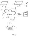
- the present diagnostic display system is generally designated 10, and is designed to provide an efficient way to diagnose avionics components of an aircraft, and also to provide enhanced displays and relations of the avionics components related to the aircraft in real time.
- a central diagnostic module or unit (CDM) 12 which regulates an overall operation of the present system.
- the CDM 12 receives at least one signal from a plurality of sensors 14 for the aircraft, and at least one parameter 16 from other related avionics systems associated with the aircraft.
- the CDM 12 receives the signals and parameters via a network 18, and displays related diagnostic information on an interactive display 20 accessible to the pilot.
- a network having a collection of computers, servers, and other hardware interconnected by communication channels is contemplated, such as the Internet, Ethernet, LAN, etc.
- the CDM 12 interfaces with the network 18, such as a wireless communication facility (e.g., a Wifi access point), and performs a point of care diagnostic test for detecting and qualifying the operational status of the aircraft.
- a wireless communication facility e.g., a Wifi access point
- the CDM 12 manages interactions between flight crew members and the present system 10 by way of a human machine interface (HMI), such as a keyboard, a touch sensitive pad or screen, a mouse, a trackball, a voice recognition system, and the like.
- HMI human machine interface
- the interactive display device 20 (e.g., textual and graphical) is configured for receiving an input signal from the crew and/or the CDM 12.
- the crew uses an input device, such as the HMI, to graphically or textually interact with the present system 10.
- the signals and/or parameters are generally received in the CDM 12 and then transferred to the interactive display device 20 via a dedicated communication system.
- a dedicated airline datalink can be used for an aircraft diagnostic service. Further, any collaborative other and third-party database reachable by the aircraft can also be used for the diagnostic service.
- the system 10 includes the CDM 12 having a component information module 22, a detection module 24, a diagnostics module 26, a categorization module 28, and a display module 30.
- the sub-modules 22, 24, 26, 28, 30 are illustrated as children modules subordinate of the parent module CDM 12, each sub-module can be operated as a separate unit from the CDM, and other suitable combinations of sub-modules are contemplated to suit different applications.
- the CDM 12 includes an interface module 34 for providing an interface between the CDM 12, the central database 32, and the network 18.
- the interface module 34 controls operation of, for example, the sensors 14, the parameters 16, the network 18, and other related system devices, services, and applications.
- the other devices, services, and applications may include, but are not limited to, one or more software or hardware components, etc., related to the aircraft.
- the interface module 34 also receives the signals and/or parameters, which are communicated to the respective modules, such as the CDM 12, and its children modules 22, 24, 26, 28, 30.
- the component information module 22 is configured to receive the signals and parameters via the interface module 34, and provide operational status information about at least one of the avionics components of the aircraft. Specifically, the component information module 22 provides detailed operational status breakdowns or configurations of each avionics component using a plurality of status messages stored in the database 32. The status messages are selectively displayed on the interactive display device 20 in a predetermined order for providing the operational status information about the avionics components to the pilot and/or flight crew. In general, as discussed in greater detail below, the present system 10 assesses a current operational status of the aircraft by evaluating the current configuration textually and/or graphically illustrated in the display 20 for establishing a visual link or bond between the status messages associated with the avionics components of the aircraft.
- the detection module 24 is also configured to receive the signals and parameters via the interface module 32, and examine the signals and parameters for detecting any faults or anomalies of the avionics components based on a predetermined set of rules.
- the signals and parameters can be received from the component information module 22.
- the detection module 24 monitors the operational status of the aircraft for a predetermined time period, and identifies a fault or anomaly of each avionics component based on an anomaly analysis in communication with the database 32.
- the detection module 24 retrieves all or a portion of the diagnostic service data associated with the aircraft from the database 32 for assisting in identifying the faults or anomalies of a current operational status of the aircraft.
- the diagnostics module 26 is configured to analyze the detected faults or anomalies of the avionics components of the aircraft based on a set of predetermined thresholds or values. In a preferred embodiment, the diagnostics module 26 evaluates each detected fault or anomaly by applying a set of predetermined queries in response to erroneous operation of at least one of the avionics components as represented by the received signals and parameters. When the diagnostics module 26 determines that the detected fault or anomaly is out of an acceptable range based on the predetermined thresholds or values, the status messages associated with the avionics components are selected for illustration on the interactive display device 20.
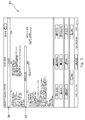
- the categorization module 28 is configured to categorize the status messages based on a hierarchical level assigned to each status message. In a preferred embodiment, as shown in FIG. 3 , the categorization module 28 divides the status messages into two distinct levels, namely an operational level (or phase) 36 and a functional level (or state) 38. For example, a status message associated with the current phase of flight is grouped in the operational level 36, and another status message associated with a future phase of the flight (e.g. an approach and landing phase) is grouped in the functional level 38.
- a global status of the aircraft is displayed using the status messages associated with the operational level 36 and the functional level 38.
- the categorization module 28 further divides the operational level 36 and the functional level 38 into one or more subcategories based on an operational connection of the avionics components.
- the operational level ALL PHASES 36 is subdivided into three subcategories, namely a flight section FLY, a navigation section NAV, and a communication section COM.
- the functional level 38 is subdivided into three subcategories, namely the flight section FLY, the navigation section NAV, and a deferred procedure section DEFERRED PROC.
- Other suitable subcategories are also contemplated.
- the display module 30 is configured to illustrate the status messages based on at least one of the hierarchical level assigned to each status message and an operational relationship between the avionics components of the aircraft.
- each section of the functional level 38 displays subordinate status messages related to a corresponding section of the parent operational level 36.
- Comprehensive illustrations of these two levels 36, 38 are described in greater detail below in paragraphs regarding FIGS. 4-8 .
- the CDM 12 can be integrated with the concept of a task scheduler disclosed in commonly assigned application no. 13/905,914 filed May 30, 2013 , now a US Patent Pub. No. 2014/0200748 , which is incorporated by reference in its entirety.
- the parent operational level 36 includes the status messages associated with all phases of the aircraft operation in at least one of the flight section FLY, the navigation section NAV, and the communication section COM.
- the flight section FLY includes the status messages describing information regarding an aircraft trajectory or piloting, such as airspeed, braking, capacity of approach, and the like.
- the navigation section NAV includes the status messages describing information regarding aircraft limitations and capacities for navigation, such as fuel, precision of position, constraint parameters (e.g., time and space), zones to be avoided, and the like.
- the communication section COM includes the status messages describing information regarding technical limitations for the communication between a cockpit of the aircraft and external entities, such as restrictions on VHF or HF frequencies, aircraft datalink services, Air Operator's Certificate (AOC), aircraft cabin, and the like.
- AOC Air Operator's Certificate
- three sections FLY, NAV, COM are shown for illustration purposes, other suitable sections and sub- sections are contemplated to suit different applications. Similarly, other suitable categorizations are also contemplated as desired.
- the child functional level 38 includes the status messages that are subordinate to the status messages of the corresponding parent operational level 36.
- the child functional level 38 includes the status messages regarding the aircraft's approach and landing operation in at least one of the flight section FLY and the navigation section NAV.
- Each status message is evaluated by the categorization module 28 based on weighted severity such that if more than one status messages are similarly related in a same section, only more penalizing or severe status messages are retained and displayed in the functional level 38 based on the weighted severity.
- only a predetermined number of status messages are displayed in each section of the child functional level 38 or the parent operational level 36 based on the corresponding weighted severity in a predetermined order.
- the status messages are displayed using a distinct color scheme based on a message type (e.g., technical limitation in cyan, general information in green, and fault / anomaly in amber).
- the display module 30 utilizes a tile display system, generally designated 40, for illustrating the status messages in accordance with a technique disclosed in commonly assigned application no. 14/171,444 filed February 3, 2014 , which is incorporated by reference in its entirety.
- the tile display system 40 includes a toggle button 42 for selectively displaying a message tile 44 associated with the toggle button 42.
- the toggle button 42 transitions between a closed state ( FIG. 6A ) and an open state ( FIG. 6B ) by selecting or clicking on the button using a dedicated input device, such as a finger tactile interaction device, a touch-sensitive screen, a digital pen and pad, a mouse, a trackball, and the like.
- a title of category (or subcategory) is displayed in the toggle button 42, and zero or more subordinate status messages associated with the category (or subcategory) are displayed in the message tile 44.
- Each status message informs the pilot and/or flight crew about potential degradation of the operational status of the aircraft.
- the status messages can be displayed using the distinct color scheme based on the message type. For example, the status message displayed in green may indicate that the specific message refers to a particular operational status but not necessarily to degradation of the corresponding avionics component. However, the status message displayed in amber may indicate that the specific message leads to an inoperative function or avionics equipment in the aircraft.
- the display module 30 automatically detects an operational relationship between the status messages of the parent operational level 36 and the child functional level 38 based on the operational connection of the avionics components, and establishes a link or bond 46 between the status messages.
- the operational relationship may refer to a cause-and-effect connection between one or more avionics components of the aircraft.
- the pilot selects or clicks on one of the status messages, i.e., "FUEL CONSUMPT INCRSD,” displayed in the parent operational level 36 using the input device.
- the display module 30 detects the operational relationship and generates the link 46 between a first status message "FUEL CONSUMPT INCRSD" of the parent operational level 36 selected by the pilot and a second status message "INR FLAPS" is then displayed in the message tile 44 of the functional level 38.
- at least one of the first and second status messages are highlighted for display.
- the link 46 indicates the operational relationship between the first and second status messages, thereby immediately drawing attention of the pilot or flight crew to the potential degradation of corresponding avionics components.
- the pilot can readily determine which status messages require immediate attention for correction and recovery.
- the pilot understands that the fuel overconsumption is impacting or caused by the aircraft navigation, and this anomaly may be related to an operational failure or change in the configuration of the wing slats or flaps.
- the link 46 effectively and promptly provides a dedicated indication of an actual or potential cause or location of the trouble when the fault is detected by the diagnostic system 10. As a result, a prompt and efficient corrective course of action may be performed, and a reliable navigation may be provided while the aircraft is in operation.
- the toggle button 42 can also be pointed when the button is in the closed state. Also, although an arrow is shown for the link 46, other suitable linkage types using a blinking pattern are contemplated as known in the art.
- FIG. 9 an exemplary diagnostic display method or process of executing the present system 10 is illustrated.
- step 100 the component information module 22 receives the signals from the sensors 14 and the parameters 16 from the avionics systems via the interface module 34.
- step 104 the component information module 22 provides operational status information about at least one of the avionics components of the aircraft based on the received signals and parameters. As discussed above, the component information module 22 provides detailed operational status breakdowns or configurations of each avionics component using the status messages stored in the database 32.
- the detection module 24 receives the signals and parameters via the interface module 32, and examines the signals and parameters for detecting any faults or anomalies of the avionics components based on a predetermined set of rules. During operation, the detection module 24 monitors the operational status of the aircraft for a predetermined time period, and identifies the fault or anomaly of each avionics component based on the anomaly analysis in communication with the database 32.
- step 108 the diagnostics module 26 analyzes the detected faults or anomalies of the avionics components of the aircraft based on a set of predetermined thresholds or values.
- control proceeds to step 110. Otherwise, control returns to step 102 and continues the diagnostic process.
- the categorization module 28 determines to which level each status message belongs based on a hierarchical level assigned to each status message. For example, the categorization module 28 classifies the status messages indicating the faults or anomalies into one of the operational level 36 and the functional level 38. In step 112, the categorization module 28 further divides the levels 36, 38 into one or more subcategories based on the operational connection of the avionics components.
- step 114 the display module 30 automatically detects an operational relationship between the status messages of the parent operational level 36 and the child functional level 38 based on the operational connection of the avionics components, and establishes a link or bond 46 between the status messages.
- step 116 the display module 30 illustrates the link 46 defining a path or connection between the status messages displayed in the parent operational level 36 and the child functional level 38 when one of the status messages in the parent level is selected.
- step 118 in another alternative embodiment, the display module 30 illustrates the link 46 in a reverse order defining a path or connection between the status messages displayed in the parent operational level 36 and the child functional level 38 when one of the status messages in the child level is selected.
- the method ends at step 120 which could include a return to step 102.
Landscapes
- Engineering & Computer Science (AREA)
- Physics & Mathematics (AREA)
- General Physics & Mathematics (AREA)
- Manufacturing & Machinery (AREA)
- Transportation (AREA)
- Aviation & Aerospace Engineering (AREA)
- Human Computer Interaction (AREA)
- Automation & Control Theory (AREA)
- Testing Of Devices, Machine Parts, Or Other Structures Thereof (AREA)
- User Interface Of Digital Computer (AREA)
- Traffic Control Systems (AREA)
Abstract
Description
- The present invention generally relates to aircraft display systems, and in particular relates to a diagnostic system for operation of an aircraft using an interactive display device.
- Troubleshooting and maintenance of avionics equipment in an aircraft are important tasks for proper operation of the aircraft during flight and taxiing. Even the most sophisticated and complex diagnostic systems must be regularly reviewed by flight crew and pilots for recovering potential faults of the avionics equipment. Most electronic instrument systems used in the aircraft receive signals and parameters from various sensors, and display the signals and parameters on one or more single or multicolor display units on an instrument panel. The diagnostic system evaluates changes in the signals and parameters based on programmed thresholds, and warns the flight crew of any changes that could signal impending technical issues. Typically, any of the sensed signals and parameters are automatically displayed when the signals and parameters fall outside of their allowable range of operation.
- Typically, during preparation for taxiing, take-off, cruise or landing, the pilot performs many diagnostic tasks. The pilot determines an accurate navigational course of the aircraft by examining current conditions of the avionic systems. Then, the pilot prepares the aircraft for optimizing the operation of the aircraft according to Air Traffic Control (ATC) constraints. As a result, the workloads of the pilot and flight crew become significant and convoluted during operation. Thus, it is important to perform prompt and effective examination of the avionics equipment, and confirm that the avionics equipment is operating smoothly without any interruptions and delays, or that the operational impact of any avionics equipment failure is promptly and clearly understood.
- A conventional configuration of the display unit renders the links between these signals and parameters not readily recognizable, and creates confusion and misunderstanding prone to improper or ill-timed adjustments of the avionics equipment during operation leading to unnecessary workload. As an example only, it may be unclear whether a sudden change in a fuel consumption rate influences a navigation ability of the aircraft during take-off or landing. In some cases, the pilot may have to spend a relatively considerable amount of time evaluating information gleaned from the signals and parameters before initiating corrective actions.
- Further, various equipment fault information is observed and considered independently in an isolated manner, separately from other related fault information that may also need to be reviewed simultaneously. It takes time for the pilot to gather all relevant information and determine the effective course of action for correcting the detected faults of the aircraft. The conventional configuration does not always effectively and promptly provide an actual or potential root cause or location of the trouble when the fault is detected by the diagnostic system.
- Therefore, there is a need for developing an improved diagnostic display system and method such that the diagnostic display system facilitates an accurate depiction of faults root cause as well as impacts on aircraft abilities, thereby easing correction of the faults for sustaining reliable navigation and control of the aircraft.
- Advantages are achieved by the present diagnostic display system which includes an improved aircraft status message database for storing specific information relating to operational relationships between avionics components of the aircraft in a suitable dimensional coordinate system. The present diagnostic display system further includes a computer processor coupled to databases and programmed to perform tasks and display relational information of the avionics components. Included in the present status message database is a status description of each component, and is designed to take up minimal space in memory such that it can be readily embedded in different applications in the aircraft.
- As discussed in greater detail below, the present diagnostic display system provides an enhanced diagnostic function for avionics operations using various signals and parameters received from aircraft sensors and other related systems. In a preferred embodiment, it is contemplated that a system and method is provided for processing multiple sources of data for diagnosing avionics components of the aircraft using the status message database. Also included in the present diagnostic display system is that a system and method configured for correlating various sources of avionic components based on operational relationships between the avionics components. Further, the present diagnostic display system provides enhanced displays and relations of the avionics components related to the aircraft in real time.
- The present diagnostic display system automatically generates a relationship link or bond between the avionics systems for the aircraft based on the information stored in the status message database. As a result, the pilots clearly understand the causes and consequences of the fault and can perform a prompt and efficient corrective course of action while the aircraft is operated. Thus, the present diagnostic display system provides a reliable means of assisting in the operation of the aircraft without causing delays in the fault treatment.
- In one embodiment, a diagnostic display system is provided for diagnosing avionics components of an aircraft using an interactive display accessible to a user in real time. A central diagnostic module receives at least one signal from a plurality of sensors for the aircraft, and at least one parameter from a related avionics system associated with the aircraft. A component information module provides operational status information about at least one of the avionics components of the aircraft, and provides a detailed operational status configuration of each avionics component using a plurality of status messages stored in a database via a network. The central diagnostic module assesses a current operational status of the aircraft by evaluating the operational status configuration illustrated in the display for establishing a visual link between the status messages associated with the avionics components of the aircraft.
- In another embodiment, a computer-implemented method is provided for diagnosing avionics components of an aircraft using an interactive display accessible to a user in real time. Included in the method are receiving at least one signal from a plurality of sensors for the aircraft, and at least one parameter from a related avionics system associated with the aircraft; providing operational status information about at least one of the avionics components of the aircraft; providing a detailed operational status configuration of each avionics component using a plurality of status messages stored in a database via a network; assessing a current operational status of the aircraft by evaluating the operational status configuration illustrated in the display; and establishing a visual link between the plurality of status messages associated with the avionics components of the aircraft.
- The foregoing and other aspects and features of the invention will become apparent to those of reasonable skill in the art from the following detailed description, as considered in conjunction with the accompanying drawings.
-
FIG. 1 illustrates an exemplary visualization of the present diagnostic display system having a central diagnostic module; -
FIG. 2 is a functional block diagram of the present diagnostic display system, featuring children modules of the central diagnostic module ofFIG. 1 ; -
FIG. 3 illustrates an exemplary visualization of a status message display presented by the present diagnostic display system; -
FIG. 4 illustrates an exemplary visualization of operational levels categorized by the present diagnostic display system; -
FIG. 5 illustrates an exemplary visualization of the status message display, featuring parent and subordinate status messages categorized by the present diagnostic display system; -
FIGS. 6A-6B illustrate an exemplary visualization of a tile system utilized by the present diagnostic display system for displaying subordinate messages; -
FIG. 7 illustrates an exemplary visualization of the tile system ofFIG. 6 when expanded for displaying the subordinate messages; -
FIG. 8 illustrates an exemplary visualization of the tile system ofFIG. 6 , featuring a linkage established by the present diagnostic display system between the parent status message and the subordinate message; and -
FIG. 9 is a flow chart of an exemplary method of executing the present diagnostic display system. - Preferred embodiments of the present invention are described below by way of example only, with reference to the accompanying drawings. Further, the following description is merely exemplary in nature and is in no way intended to limit the invention, its application, or uses. As used herein, the term "module" or "unit" may refer to, be part of, or include an Application Specific Integrated Circuit (ASIC), an electronic circuit, a processor (shared, dedicated, or group) and/or memory (shared, dedicated, or group) that executes one or more software or firmware programs, a combinational logic circuit, and/or other suitable components that provide the described functionality. Thus, while this invention includes particular examples and arrangements of the modules, the scope of the present system should not be so limited since other modifications will become apparent to the skilled practitioner.
- Referring now to
FIG. 1 , the present diagnostic display system is generally designated 10, and is designed to provide an efficient way to diagnose avionics components of an aircraft, and also to provide enhanced displays and relations of the avionics components related to the aircraft in real time. Included in thepresent system 10 is a central diagnostic module or unit (CDM) 12, which regulates an overall operation of the present system. In general, the CDM 12 receives at least one signal from a plurality ofsensors 14 for the aircraft, and at least oneparameter 16 from other related avionics systems associated with the aircraft. - Specifically, the
CDM 12 receives the signals and parameters via anetwork 18, and displays related diagnostic information on aninteractive display 20 accessible to the pilot. Any type of computer network having a collection of computers, servers, and other hardware interconnected by communication channels is contemplated, such as the Internet, Ethernet, LAN, etc. In a preferred embodiment, theCDM 12 interfaces with thenetwork 18, such as a wireless communication facility (e.g., a Wifi access point), and performs a point of care diagnostic test for detecting and qualifying the operational status of the aircraft. - The
CDM 12 manages interactions between flight crew members and thepresent system 10 by way of a human machine interface (HMI), such as a keyboard, a touch sensitive pad or screen, a mouse, a trackball, a voice recognition system, and the like. The interactive display device 20 (e.g., textual and graphical) is configured for receiving an input signal from the crew and/or theCDM 12. In one embodiment, the crew uses an input device, such as the HMI, to graphically or textually interact with thepresent system 10. The signals and/or parameters are generally received in theCDM 12 and then transferred to theinteractive display device 20 via a dedicated communication system. A dedicated airline datalink can be used for an aircraft diagnostic service. Further, any collaborative other and third-party database reachable by the aircraft can also be used for the diagnostic service. - Referring now to
FIGS. 2 and3 , it is preferred that thesystem 10 includes theCDM 12 having acomponent information module 22, a detection module 24, adiagnostics module 26, acategorization module 28, and adisplay module 30. Although thesub-modules parent module CDM 12, each sub-module can be operated as a separate unit from the CDM, and other suitable combinations of sub-modules are contemplated to suit different applications. - All relevant information can be stored in a
central database 32, e.g., as a data storage device and/or a machine readable data storage medium carrying computer programs, for retrieval by theCDM 12 and its children modules. Further, theCDM 12 includes aninterface module 34 for providing an interface between theCDM 12, thecentral database 32, and thenetwork 18. Theinterface module 34 controls operation of, for example, thesensors 14, theparameters 16, thenetwork 18, and other related system devices, services, and applications. The other devices, services, and applications may include, but are not limited to, one or more software or hardware components, etc., related to the aircraft. Theinterface module 34 also receives the signals and/or parameters, which are communicated to the respective modules, such as theCDM 12, and itschildren modules - The
component information module 22 is configured to receive the signals and parameters via theinterface module 34, and provide operational status information about at least one of the avionics components of the aircraft. Specifically, thecomponent information module 22 provides detailed operational status breakdowns or configurations of each avionics component using a plurality of status messages stored in thedatabase 32. The status messages are selectively displayed on theinteractive display device 20 in a predetermined order for providing the operational status information about the avionics components to the pilot and/or flight crew. In general, as discussed in greater detail below, thepresent system 10 assesses a current operational status of the aircraft by evaluating the current configuration textually and/or graphically illustrated in thedisplay 20 for establishing a visual link or bond between the status messages associated with the avionics components of the aircraft. - As is the case with the
component information module 22, the detection module 24 is also configured to receive the signals and parameters via theinterface module 32, and examine the signals and parameters for detecting any faults or anomalies of the avionics components based on a predetermined set of rules. Optionally, the signals and parameters can be received from thecomponent information module 22. In use, the detection module 24 monitors the operational status of the aircraft for a predetermined time period, and identifies a fault or anomaly of each avionics component based on an anomaly analysis in communication with thedatabase 32. The detection module 24 retrieves all or a portion of the diagnostic service data associated with the aircraft from thedatabase 32 for assisting in identifying the faults or anomalies of a current operational status of the aircraft. - The
diagnostics module 26 is configured to analyze the detected faults or anomalies of the avionics components of the aircraft based on a set of predetermined thresholds or values. In a preferred embodiment, thediagnostics module 26 evaluates each detected fault or anomaly by applying a set of predetermined queries in response to erroneous operation of at least one of the avionics components as represented by the received signals and parameters. When thediagnostics module 26 determines that the detected fault or anomaly is out of an acceptable range based on the predetermined thresholds or values, the status messages associated with the avionics components are selected for illustration on theinteractive display device 20. - The
categorization module 28 is configured to categorize the status messages based on a hierarchical level assigned to each status message. In a preferred embodiment, as shown inFIG. 3 , thecategorization module 28 divides the status messages into two distinct levels, namely an operational level (or phase) 36 and a functional level (or state) 38. For example, a status message associated with the current phase of flight is grouped in theoperational level 36, and another status message associated with a future phase of the flight (e.g. an approach and landing phase) is grouped in thefunctional level 38. - As shown in
FIG. 3 , a global status of the aircraft is displayed using the status messages associated with theoperational level 36 and thefunctional level 38. In a preferred embodiment, thecategorization module 28 further divides theoperational level 36 and thefunctional level 38 into one or more subcategories based on an operational connection of the avionics components. For example, the operational level ALLPHASES 36 is subdivided into three subcategories, namely a flight section FLY, a navigation section NAV, and a communication section COM. Similarly, thefunctional level 38 is subdivided into three subcategories, namely the flight section FLY, the navigation section NAV, and a deferred procedure section DEFERRED PROC. Other suitable subcategories are also contemplated. - The
display module 30 is configured to illustrate the status messages based on at least one of the hierarchical level assigned to each status message and an operational relationship between the avionics components of the aircraft. As an example, each section of thefunctional level 38 displays subordinate status messages related to a corresponding section of the parentoperational level 36. Comprehensive illustrations of these twolevels FIGS. 4-8 . Further, theCDM 12 can be integrated with the concept of a task scheduler disclosed in commonly assigned application no.13/905,914 filed May 30, 2013 US Patent Pub. No. 2014/0200748 , which is incorporated by reference in its entirety. - Referring now to
FIGS. 4 and 5 , it is preferred that the parentoperational level 36 includes the status messages associated with all phases of the aircraft operation in at least one of the flight section FLY, the navigation section NAV, and the communication section COM. For example, the flight section FLY includes the status messages describing information regarding an aircraft trajectory or piloting, such as airspeed, braking, capacity of approach, and the like. The navigation section NAV includes the status messages describing information regarding aircraft limitations and capacities for navigation, such as fuel, precision of position, constraint parameters (e.g., time and space), zones to be avoided, and the like. The communication section COM includes the status messages describing information regarding technical limitations for the communication between a cockpit of the aircraft and external entities, such as restrictions on VHF or HF frequencies, aircraft datalink services, Air Operator's Certificate (AOC), aircraft cabin, and the like. Although three sections FLY, NAV, COM are shown for illustration purposes, other suitable sections and sub- sections are contemplated to suit different applications. Similarly, other suitable categorizations are also contemplated as desired. - As shown in
FIG. 5 , the childfunctional level 38 includes the status messages that are subordinate to the status messages of the corresponding parentoperational level 36. For example, the childfunctional level 38 includes the status messages regarding the aircraft's approach and landing operation in at least one of the flight section FLY and the navigation section NAV. Each status message is evaluated by thecategorization module 28 based on weighted severity such that if more than one status messages are similarly related in a same section, only more penalizing or severe status messages are retained and displayed in thefunctional level 38 based on the weighted severity. For example, only a predetermined number of status messages are displayed in each section of the childfunctional level 38 or the parentoperational level 36 based on the corresponding weighted severity in a predetermined order. In one embodiment, the status messages are displayed using a distinct color scheme based on a message type (e.g., technical limitation in cyan, general information in green, and fault / anomaly in amber). - Referring now to
FIGS. 6A-6B and7 , it is preferred that thedisplay module 30 utilizes a tile display system, generally designated 40, for illustrating the status messages in accordance with a technique disclosed in commonly assigned application no.14/171,444 filed February 3, 2014 - As best shown in
FIGS. 6A-6B , thetile display system 40 includes atoggle button 42 for selectively displaying amessage tile 44 associated with thetoggle button 42. In use, thetoggle button 42 transitions between a closed state (FIG. 6A ) and an open state (FIG. 6B ) by selecting or clicking on the button using a dedicated input device, such as a finger tactile interaction device, a touch-sensitive screen, a digital pen and pad, a mouse, a trackball, and the like. A title of category (or subcategory) is displayed in thetoggle button 42, and zero or more subordinate status messages associated with the category (or subcategory) are displayed in themessage tile 44. - Each status message informs the pilot and/or flight crew about potential degradation of the operational status of the aircraft.
- As described above, the status messages can be displayed using the distinct color scheme based on the message type. For example, the status message displayed in green may indicate that the specific message refers to a particular operational status but not necessarily to degradation of the corresponding avionics component. However, the status message displayed in amber may indicate that the specific message leads to an inoperative function or avionics equipment in the aircraft.
- Referring now to
FIG. 8 , it is contemplated that thedisplay module 30 automatically detects an operational relationship between the status messages of the parentoperational level 36 and the childfunctional level 38 based on the operational connection of the avionics components, and establishes a link orbond 46 between the status messages. The operational relationship may refer to a cause-and-effect connection between one or more avionics components of the aircraft. - As an example only, the pilot selects or clicks on one of the status messages, i.e., "FUEL CONSUMPT INCRSD," displayed in the parent
operational level 36 using the input device. Next, thedisplay module 30 detects the operational relationship and generates thelink 46 between a first status message "FUEL CONSUMPT INCRSD" of the parentoperational level 36 selected by the pilot and a second status message "INR FLAPS" is then displayed in themessage tile 44 of thefunctional level 38. Optionally, at least one of the first and second status messages are highlighted for display. - The
link 46 indicates the operational relationship between the first and second status messages, thereby immediately drawing attention of the pilot or flight crew to the potential degradation of corresponding avionics components. In this configuration, the pilot can readily determine which status messages require immediate attention for correction and recovery. By way of example shown inFIG 8 , the pilot understands that the fuel overconsumption is impacting or caused by the aircraft navigation, and this anomaly may be related to an operational failure or change in the configuration of the wing slats or flaps. Thelink 46 effectively and promptly provides a dedicated indication of an actual or potential cause or location of the trouble when the fault is detected by thediagnostic system 10. As a result, a prompt and efficient corrective course of action may be performed, and a reliable navigation may be provided while the aircraft is in operation. Although themessage tile 44 is pointed with an arrow head of thelink 46, thetoggle button 42 can also be pointed when the button is in the closed state. Also, although an arrow is shown for thelink 46, other suitable linkage types using a blinking pattern are contemplated as known in the art. - Referring now to
FIG. 9 , an exemplary diagnostic display method or process of executing thepresent system 10 is illustrated. - Although the following steps are primarily described with respect to the embodiments of
FIGS. 1-8 , it should be understood that the steps within the method may be modified and executed in a different order or sequence without altering the principles of the present invention. - The method begins at
step 100. Instep 102, thecomponent information module 22 receives the signals from thesensors 14 and theparameters 16 from the avionics systems via theinterface module 34. Instep 104, thecomponent information module 22 provides operational status information about at least one of the avionics components of the aircraft based on the received signals and parameters. As discussed above, thecomponent information module 22 provides detailed operational status breakdowns or configurations of each avionics component using the status messages stored in thedatabase 32. - In
step 106, the detection module 24 receives the signals and parameters via theinterface module 32, and examines the signals and parameters for detecting any faults or anomalies of the avionics components based on a predetermined set of rules. During operation, the detection module 24 monitors the operational status of the aircraft for a predetermined time period, and identifies the fault or anomaly of each avionics component based on the anomaly analysis in communication with thedatabase 32. - In
step 108, thediagnostics module 26 analyzes the detected faults or anomalies of the avionics components of the aircraft based on a set of predetermined thresholds or values. When at least one of the signals or parameters are out of acceptable ranges defined by the set of predetermined thresholds or values, control proceeds to step 110. Otherwise, control returns to step 102 and continues the diagnostic process. - In
step 110, thecategorization module 28 determines to which level each status message belongs based on a hierarchical level assigned to each status message. For example, thecategorization module 28 classifies the status messages indicating the faults or anomalies into one of theoperational level 36 and thefunctional level 38. Instep 112, thecategorization module 28 further divides thelevels - In
step 114, thedisplay module 30 automatically detects an operational relationship between the status messages of the parentoperational level 36 and the childfunctional level 38 based on the operational connection of the avionics components, and establishes a link orbond 46 between the status messages. Instep 116, thedisplay module 30 illustrates thelink 46 defining a path or connection between the status messages displayed in the parentoperational level 36 and the childfunctional level 38 when one of the status messages in the parent level is selected. - In
step 118, in another alternative embodiment, thedisplay module 30 illustrates thelink 46 in a reverse order defining a path or connection between the status messages displayed in the parentoperational level 36 and the childfunctional level 38 when one of the status messages in the child level is selected. The method ends atstep 120 which could include a return to step 102. - While at least one exemplary embodiment of the present invention has been shown and described, it should be understood that modifications, substitutions and alternatives may be apparent to one of ordinary skill in the art and can be made without departing from the scope of the invention described herein. This application is intended to cover any adaptations or variations of the specific embodiments discussed herein. In addition, in this application, the terms "comprise" or "comprising" do not exclude other elements or steps, and the terms "a" or "one" do not exclude a plural number. Furthermore, characteristics or steps which have been described with reference to one of the above exemplary embodiments may also be used in combination with other characteristics or steps of other exemplary embodiments described above.
Claims (20)
- A diagnostic display system (10) for diagnosing avionics components of an aircraft using an interactive display device (20) accessible to a user in real time, the system comprising:a central diagnostic module (12) configured for receiving at least one signal from a plurality of sensors (14) for the aircraft, and at least one parameter (16) from a related avionics system associated with the aircraft; anda component information module (22) configured for providing operational status information about at least one of the avionics components of the aircraft, and providing a detailed operational status configuration of each avionics component using a plurality of status messages stored in a database (32) via a network (18);characterized in that the central diagnostic module (12) assesses a current operational status of the aircraft by evaluating the operational status configuration illustrated in the interactive display device (20 for establishing a visual link between the plurality of status messages associated with the avionics components of the aircraft.
- The diagnostic display system (10) of claim 1, characterized in that the system (10) further comprising an interface module (34) configured for controlling operation of the plurality of sensors (14), the at least one parameter (16), the network (18), and other related system devices, services, and applications associated with the diagnostic display system (10).
- The diagnostic display system (10) of claim 1, characterized in that the system (10) further comprising a detection module (24) configured for examining the at least one signal and parameter (16) for detecting a fault of the avionics component based on a predetermined set of rules.
- The diagnostic display system (10) of claim 3, characterized in that the detection module (24) monitors the operational status of the aircraft for a predetermined time period, and identifies the fault of the avionics component based on an anomaly analysis in communication with the database (32).
- The diagnostic display system (10) of claim 3, characterized in that the detection module (24) retrieves at least a portion of diagnostic service data associated with the aircraft from the database (32) for assisting in identifying the fault of a current operational status of the aircraft.
- The diagnostic display system (10) of claim 1, further comprising a diagnostics module (26) configured for analyzing a detected fault of the avionics component of the aircraft based on a set of predetermined thresholds.
- The diagnostic display system (10) of claim 6, characterized in that the diagnostics module (26) evaluates the detected fault by applying a set of predetermined queries in response to erroneous operation of at least one of the avionics components as represented by the at least one signal and parameter.
- The diagnostic display system (10) of claim 6, characterized in that when the diagnostics module (26) determines that the detected fault is out of an acceptable range based on the predetermined thresholds, the plurality of status messages associated with the avionics components are selected for illustration on theinteractive display device (20).
- The diagnostic display system (10) of claim 1, characterized in that the system (10) further comprising a categorization module (28) configured for categorizing the plurality of status messages based on a hierarchical level assigned to each status message.
- The diagnostic display system (10) of claim 9, characterized in that the categorization module (28) divides the plurality of status messages into an operational level (36 and a functional level (38).
- The diagnostic display system (10) of claim 10, characterized in that the categorization module (28) further divides at least one of the operational and functional levels (36, 38) into one or more subcategories based on an operational connection of the avionics components.
- The diagnostic display system (10) of claim 10, characterized in that the operational level (36) includes the plurality of status messages associated with at least one of a flight section (FLY), a navigation section (NAV), and a communication section (COM).
- The diagnostic display system (10) of claim 10, characterized in that the functional level (38) includes the plurality of status messages that are subordinate to the plurality of status messages of the corresponding operational level (36).
- The diagnostic display system (10) of claim 1, characterized in that the system (10) further comprising a display module (30) configured for illustrating the plurality of status messages based on at least one of a hierarchical level assigned to each status message and an operational relationship between the avionics components of the aircraft.
- The diagnostic display system (10) of claim 1, characterized in that the system (10) further comprising a tile display system (40) for illustrating the plurality of status messages, the tile display system (40) including a toggle button (42) for selectively displaying a message tile associated with the toggle button (42).
- A computer-implemented method for diagnosing avionics components of an aircraft using an interactive display device (20) accessible to a user in real time, characterized in that the method comprising:receiving at least one signal from a plurality of sensors (14) for the aircraft, and at least one parameter (16) from a related avionics system associated with the aircraft;providing operational status information about at least one of the avionics components of the aircraft;providing a detailed operational status configuration of each avionics component using a plurality of status messages stored in a database (32) via a network (18);assessing a current operational status of the aircraft by evaluating the operational status configuration illustrated in the display; andestablishing a visual link between the plurality of status messages associated with the avionics components of the aircraft.
- The method of claim 16, characterized in that the method further comprising examining the at least one signal (14) and parameter (16) for detecting a fault of the avionics component based on a predetermined set of rules.
- The method of claim 16, characterized in that the method further comprising analyzing a detected fault of the avionics component of the aircraft based on a set of predetermined thresholds.
- The method of claim 16, characterized in that the method further comprising categorizing the plurality of status messages based on a hierarchical level assigned to each status message.
- The method of claim 16, characterized in that the method further comprising illustrating the plurality of status messages based on at least one of a hierarchical level assigned to each status message and an operational relationship between the avionics components of the aircraft.
Applications Claiming Priority (1)
| Application Number | Priority Date | Filing Date | Title |
|---|---|---|---|
| US14/575,047 US9309009B1 (en) | 2014-12-18 | 2014-12-18 | Interactive diagnostic display system and method for an aircraft |
Publications (2)
| Publication Number | Publication Date |
|---|---|
| EP3035141A1 true EP3035141A1 (en) | 2016-06-22 |
| EP3035141B1 EP3035141B1 (en) | 2019-11-27 |
Family
ID=54754477
Family Applications (1)
| Application Number | Title | Priority Date | Filing Date |
|---|---|---|---|
| EP15196809.6A Not-in-force EP3035141B1 (en) | 2014-12-18 | 2015-11-27 | Interactive diagnostic display system and method for an aircraft |
Country Status (2)
| Country | Link |
|---|---|
| US (1) | US9309009B1 (en) |
| EP (1) | EP3035141B1 (en) |
Families Citing this family (8)
| Publication number | Priority date | Publication date | Assignee | Title |
|---|---|---|---|---|
| EP3229445B1 (en) | 2016-04-06 | 2018-08-08 | The Boeing Company | A system and a computer-implemented method for multi path communication with an unmanned aerial vehicle during a mission |
| US10019855B2 (en) | 2016-05-18 | 2018-07-10 | The Boeing Company | System and method for operational phase detection |
| CN106774271B (en) * | 2017-01-03 | 2020-06-23 | 中车株洲电力机车有限公司 | Urban rail transit vehicle fault diagnosis and display system |
| EP3370386B1 (en) * | 2017-03-03 | 2019-05-15 | The Boeing Company | A system and a computer-implemented method for machine-to-machine authentication of an apparatus |
| US11459105B2 (en) | 2020-03-04 | 2022-10-04 | Rockwell Collins, Inc. | Reconfigurable avionics systems heatmap |
| CN112537460B (en) * | 2020-12-10 | 2024-11-29 | 广州新科宇航科技有限公司 | B737 aircraft engine APU fire-extinguishing bottle loop test protection device |
| CN115393973B (en) * | 2022-07-13 | 2024-12-03 | 陕西千山航空电子有限责任公司 | Aeroengine indication and aircrew alarm information generation device |
| CN117110766B (en) * | 2023-10-18 | 2024-01-09 | 沈阳圣飞航空科技有限公司 | Detection system and method for detecting avionics control device |
Citations (4)
| Publication number | Priority date | Publication date | Assignee | Title |
|---|---|---|---|---|
| US20100145553A1 (en) * | 2008-08-20 | 2010-06-10 | Airbus Operations | Method and device for sharing data between on-board systems in an aircraft |
| US20100161157A1 (en) * | 2008-12-19 | 2010-06-24 | Thales | Device for managing piloting tasks carried out by a crew of an aircraft |
| US20130274994A1 (en) * | 2010-12-23 | 2013-10-17 | Thales | Centralized Maintenance Device for Aircraft |
| US20140200748A1 (en) * | 2013-01-11 | 2014-07-17 | Airbus Operations Sas | Systems for tasks guidance of operations management in an aircraft cockpit |
Family Cites Families (2)
| Publication number | Priority date | Publication date | Assignee | Title |
|---|---|---|---|---|
| AU2002334708A1 (en) * | 2001-10-01 | 2003-04-14 | Kline And Walker, Llc | Pfn/trac system faa upgrades for accountable remote and robotics control |
| CN102416821A (en) * | 2011-07-27 | 2012-04-18 | 中国国际航空股份有限公司 | Data processing method for aircraft system |
-
2014
- 2014-12-18 US US14/575,047 patent/US9309009B1/en active Active
-
2015
- 2015-11-27 EP EP15196809.6A patent/EP3035141B1/en not_active Not-in-force
Patent Citations (4)
| Publication number | Priority date | Publication date | Assignee | Title |
|---|---|---|---|---|
| US20100145553A1 (en) * | 2008-08-20 | 2010-06-10 | Airbus Operations | Method and device for sharing data between on-board systems in an aircraft |
| US20100161157A1 (en) * | 2008-12-19 | 2010-06-24 | Thales | Device for managing piloting tasks carried out by a crew of an aircraft |
| US20130274994A1 (en) * | 2010-12-23 | 2013-10-17 | Thales | Centralized Maintenance Device for Aircraft |
| US20140200748A1 (en) * | 2013-01-11 | 2014-07-17 | Airbus Operations Sas | Systems for tasks guidance of operations management in an aircraft cockpit |
Also Published As
| Publication number | Publication date |
|---|---|
| EP3035141B1 (en) | 2019-11-27 |
| US9309009B1 (en) | 2016-04-12 |
Similar Documents
| Publication | Publication Date | Title |
|---|---|---|
| EP3035141B1 (en) | Interactive diagnostic display system and method for an aircraft | |
| CN107545095B (en) | Predictive method and system for structural repair during aircraft overhaul | |
| US8321078B2 (en) | Method and device for assisting in the control of the on-board systems in a aircraft | |
| US8487785B2 (en) | Device for formulating the alerts of an aircraft system | |
| CN102460516B (en) | Method and device for processing faults | |
| EP2882647B1 (en) | Checklist display system, method and graphical display therefor | |
| US6732063B2 (en) | Method of identifying abnormal behavior in a fleet of vehicles | |
| US10186146B2 (en) | Abnormality detection device, abnormality detection system, and method | |
| US8497784B1 (en) | Touch screen clickable crew alert system control | |
| US20090292951A1 (en) | Method and device for fault location in a system | |
| US20140200748A1 (en) | Systems for tasks guidance of operations management in an aircraft cockpit | |
| US20110102192A1 (en) | Method, Apparatus And Computer Program Product For Displaying Forecast Weather Products With Actual And Predicted Ownship | |
| Fayollas et al. | An approach for assessing the impact of dependability on usability: application to interactive cockpits | |
| EP2674826A1 (en) | Failure analysis validation and visualization | |
| CN110018948A (en) | For analyzing the system and method with the mistake in response log file | |
| Johnson | A review of fault management techniques used in safety-critical avionic systems | |
| US10099801B2 (en) | Consolidated flight deck task list based on alerting and checklist items | |
| Vakil et al. | Approaches to mitigating complexity-driven issues in commercial autoflight systems | |
| US10614392B1 (en) | Graphical flight dashboard display and method | |
| CA3064926A1 (en) | A method for post-flight diagnosis of aircraft landing process | |
| US20130169447A1 (en) | Display processing system, display processing method, and program | |
| CN109116831A (en) | The design method of the modal aliasing fault logic door of human-computer interaction Dynamic fault tree | |
| Noyes et al. | Aircraft warning systems: application of model-based reasoning techniques | |
| Smith et al. | Design and implementation of aircraft system health management (ASHM) utilizing existing data feeds | |
| US20230356860A1 (en) | System contextual information manager |
Legal Events
| Date | Code | Title | Description |
|---|---|---|---|
| PUAI | Public reference made under article 153(3) epc to a published international application that has entered the european phase |
Free format text: ORIGINAL CODE: 0009012 |
|
| AK | Designated contracting states |
Kind code of ref document: A1 Designated state(s): AL AT BE BG CH CY CZ DE DK EE ES FI FR GB GR HR HU IE IS IT LI LT LU LV MC MK MT NL NO PL PT RO RS SE SI SK SM TR |
|
| AX | Request for extension of the european patent |
Extension state: BA ME |
|
| STAA | Information on the status of an ep patent application or granted ep patent |
Free format text: STATUS: REQUEST FOR EXAMINATION WAS MADE |
|
| 17P | Request for examination filed |
Effective date: 20161222 |
|
| RBV | Designated contracting states (corrected) |
Designated state(s): AL AT BE BG CH CY CZ DE DK EE ES FI FR GB GR HR HU IE IS IT LI LT LU LV MC MK MT NL NO PL PT RO RS SE SI SK SM TR |
|
| GRAP | Despatch of communication of intention to grant a patent |
Free format text: ORIGINAL CODE: EPIDOSNIGR1 |
|
| RIC1 | Information provided on ipc code assigned before grant |
Ipc: G05B 23/02 20060101AFI20190520BHEP |
|
| STAA | Information on the status of an ep patent application or granted ep patent |
Free format text: STATUS: GRANT OF PATENT IS INTENDED |
|
| INTG | Intention to grant announced |
Effective date: 20190627 |
|
| GRAS | Grant fee paid |
Free format text: ORIGINAL CODE: EPIDOSNIGR3 |
|
| GRAA | (expected) grant |
Free format text: ORIGINAL CODE: 0009210 |
|
| STAA | Information on the status of an ep patent application or granted ep patent |
Free format text: STATUS: THE PATENT HAS BEEN GRANTED |
|
| AK | Designated contracting states |
Kind code of ref document: B1 Designated state(s): AL AT BE BG CH CY CZ DE DK EE ES FI FR GB GR HR HU IE IS IT LI LT LU LV MC MK MT NL NO PL PT RO RS SE SI SK SM TR |
|
| REG | Reference to a national code |
Ref country code: GB Ref legal event code: FG4D |
|
| REG | Reference to a national code |
Ref country code: CH Ref legal event code: EP |
|
| REG | Reference to a national code |
Ref country code: AT Ref legal event code: REF Ref document number: 1207403 Country of ref document: AT Kind code of ref document: T Effective date: 20191215 |
|
| REG | Reference to a national code |
Ref country code: DE Ref legal event code: R096 Ref document number: 602015042424 Country of ref document: DE |
|
| REG | Reference to a national code |
Ref country code: IE Ref legal event code: FG4D |
|
| REG | Reference to a national code |
Ref country code: NL Ref legal event code: MP Effective date: 20191127 |
|
| REG | Reference to a national code |
Ref country code: LT Ref legal event code: MG4D |
|
| PG25 | Lapsed in a contracting state [announced via postgrant information from national office to epo] |
Ref country code: GR Free format text: LAPSE BECAUSE OF FAILURE TO SUBMIT A TRANSLATION OF THE DESCRIPTION OR TO PAY THE FEE WITHIN THE PRESCRIBED TIME-LIMIT Effective date: 20200228 Ref country code: LT Free format text: LAPSE BECAUSE OF FAILURE TO SUBMIT A TRANSLATION OF THE DESCRIPTION OR TO PAY THE FEE WITHIN THE PRESCRIBED TIME-LIMIT Effective date: 20191127 Ref country code: FI Free format text: LAPSE BECAUSE OF FAILURE TO SUBMIT A TRANSLATION OF THE DESCRIPTION OR TO PAY THE FEE WITHIN THE PRESCRIBED TIME-LIMIT Effective date: 20191127 Ref country code: BG Free format text: LAPSE BECAUSE OF FAILURE TO SUBMIT A TRANSLATION OF THE DESCRIPTION OR TO PAY THE FEE WITHIN THE PRESCRIBED TIME-LIMIT Effective date: 20200227 Ref country code: NL Free format text: LAPSE BECAUSE OF FAILURE TO SUBMIT A TRANSLATION OF THE DESCRIPTION OR TO PAY THE FEE WITHIN THE PRESCRIBED TIME-LIMIT Effective date: 20191127 Ref country code: LV Free format text: LAPSE BECAUSE OF FAILURE TO SUBMIT A TRANSLATION OF THE DESCRIPTION OR TO PAY THE FEE WITHIN THE PRESCRIBED TIME-LIMIT Effective date: 20191127 Ref country code: SE Free format text: LAPSE BECAUSE OF FAILURE TO SUBMIT A TRANSLATION OF THE DESCRIPTION OR TO PAY THE FEE WITHIN THE PRESCRIBED TIME-LIMIT Effective date: 20191127 Ref country code: NO Free format text: LAPSE BECAUSE OF FAILURE TO SUBMIT A TRANSLATION OF THE DESCRIPTION OR TO PAY THE FEE WITHIN THE PRESCRIBED TIME-LIMIT Effective date: 20200227 |
|
| PG25 | Lapsed in a contracting state [announced via postgrant information from national office to epo] |
Ref country code: IS Free format text: LAPSE BECAUSE OF FAILURE TO SUBMIT A TRANSLATION OF THE DESCRIPTION OR TO PAY THE FEE WITHIN THE PRESCRIBED TIME-LIMIT Effective date: 20200327 Ref country code: HR Free format text: LAPSE BECAUSE OF FAILURE TO SUBMIT A TRANSLATION OF THE DESCRIPTION OR TO PAY THE FEE WITHIN THE PRESCRIBED TIME-LIMIT Effective date: 20191127 Ref country code: RS Free format text: LAPSE BECAUSE OF FAILURE TO SUBMIT A TRANSLATION OF THE DESCRIPTION OR TO PAY THE FEE WITHIN THE PRESCRIBED TIME-LIMIT Effective date: 20191127 |
|
| PG25 | Lapsed in a contracting state [announced via postgrant information from national office to epo] |
Ref country code: AL Free format text: LAPSE BECAUSE OF FAILURE TO SUBMIT A TRANSLATION OF THE DESCRIPTION OR TO PAY THE FEE WITHIN THE PRESCRIBED TIME-LIMIT Effective date: 20191127 |
|
| REG | Reference to a national code |
Ref country code: CH Ref legal event code: PL |
|
| PG25 | Lapsed in a contracting state [announced via postgrant information from national office to epo] |
Ref country code: RO Free format text: LAPSE BECAUSE OF FAILURE TO SUBMIT A TRANSLATION OF THE DESCRIPTION OR TO PAY THE FEE WITHIN THE PRESCRIBED TIME-LIMIT Effective date: 20191127 Ref country code: CZ Free format text: LAPSE BECAUSE OF FAILURE TO SUBMIT A TRANSLATION OF THE DESCRIPTION OR TO PAY THE FEE WITHIN THE PRESCRIBED TIME-LIMIT Effective date: 20191127 Ref country code: ES Free format text: LAPSE BECAUSE OF FAILURE TO SUBMIT A TRANSLATION OF THE DESCRIPTION OR TO PAY THE FEE WITHIN THE PRESCRIBED TIME-LIMIT Effective date: 20191127 Ref country code: CH Free format text: LAPSE BECAUSE OF NON-PAYMENT OF DUE FEES Effective date: 20191130 Ref country code: PT Free format text: LAPSE BECAUSE OF FAILURE TO SUBMIT A TRANSLATION OF THE DESCRIPTION OR TO PAY THE FEE WITHIN THE PRESCRIBED TIME-LIMIT Effective date: 20200419 Ref country code: EE Free format text: LAPSE BECAUSE OF FAILURE TO SUBMIT A TRANSLATION OF THE DESCRIPTION OR TO PAY THE FEE WITHIN THE PRESCRIBED TIME-LIMIT Effective date: 20191127 Ref country code: LU Free format text: LAPSE BECAUSE OF NON-PAYMENT OF DUE FEES Effective date: 20191127 Ref country code: LI Free format text: LAPSE BECAUSE OF NON-PAYMENT OF DUE FEES Effective date: 20191130 Ref country code: DK Free format text: LAPSE BECAUSE OF FAILURE TO SUBMIT A TRANSLATION OF THE DESCRIPTION OR TO PAY THE FEE WITHIN THE PRESCRIBED TIME-LIMIT Effective date: 20191127 |
|
| REG | Reference to a national code |
Ref country code: BE Ref legal event code: MM Effective date: 20191130 |
|
| REG | Reference to a national code |
Ref country code: DE Ref legal event code: R097 Ref document number: 602015042424 Country of ref document: DE |
|
| PG25 | Lapsed in a contracting state [announced via postgrant information from national office to epo] |
Ref country code: MC Free format text: LAPSE BECAUSE OF FAILURE TO SUBMIT A TRANSLATION OF THE DESCRIPTION OR TO PAY THE FEE WITHIN THE PRESCRIBED TIME-LIMIT Effective date: 20191127 Ref country code: SM Free format text: LAPSE BECAUSE OF FAILURE TO SUBMIT A TRANSLATION OF THE DESCRIPTION OR TO PAY THE FEE WITHIN THE PRESCRIBED TIME-LIMIT Effective date: 20191127 Ref country code: SK Free format text: LAPSE BECAUSE OF FAILURE TO SUBMIT A TRANSLATION OF THE DESCRIPTION OR TO PAY THE FEE WITHIN THE PRESCRIBED TIME-LIMIT Effective date: 20191127 |
|
| REG | Reference to a national code |
Ref country code: AT Ref legal event code: MK05 Ref document number: 1207403 Country of ref document: AT Kind code of ref document: T Effective date: 20191127 |
|
| PLBE | No opposition filed within time limit |
Free format text: ORIGINAL CODE: 0009261 |
|
| STAA | Information on the status of an ep patent application or granted ep patent |
Free format text: STATUS: NO OPPOSITION FILED WITHIN TIME LIMIT |
|
| PG25 | Lapsed in a contracting state [announced via postgrant information from national office to epo] |
Ref country code: IE Free format text: LAPSE BECAUSE OF NON-PAYMENT OF DUE FEES Effective date: 20191127 |
|
| 26N | No opposition filed |
Effective date: 20200828 |
|
| PG25 | Lapsed in a contracting state [announced via postgrant information from national office to epo] |
Ref country code: BE Free format text: LAPSE BECAUSE OF NON-PAYMENT OF DUE FEES Effective date: 20191130 Ref country code: AT Free format text: LAPSE BECAUSE OF FAILURE TO SUBMIT A TRANSLATION OF THE DESCRIPTION OR TO PAY THE FEE WITHIN THE PRESCRIBED TIME-LIMIT Effective date: 20191127 Ref country code: PL Free format text: LAPSE BECAUSE OF FAILURE TO SUBMIT A TRANSLATION OF THE DESCRIPTION OR TO PAY THE FEE WITHIN THE PRESCRIBED TIME-LIMIT Effective date: 20191127 Ref country code: SI Free format text: LAPSE BECAUSE OF FAILURE TO SUBMIT A TRANSLATION OF THE DESCRIPTION OR TO PAY THE FEE WITHIN THE PRESCRIBED TIME-LIMIT Effective date: 20191127 |
|
| PG25 | Lapsed in a contracting state [announced via postgrant information from national office to epo] |
Ref country code: IT Free format text: LAPSE BECAUSE OF FAILURE TO SUBMIT A TRANSLATION OF THE DESCRIPTION OR TO PAY THE FEE WITHIN THE PRESCRIBED TIME-LIMIT Effective date: 20191127 |
|
| PG25 | Lapsed in a contracting state [announced via postgrant information from national office to epo] |
Ref country code: CY Free format text: LAPSE BECAUSE OF FAILURE TO SUBMIT A TRANSLATION OF THE DESCRIPTION OR TO PAY THE FEE WITHIN THE PRESCRIBED TIME-LIMIT Effective date: 20191127 |
|
| PG25 | Lapsed in a contracting state [announced via postgrant information from national office to epo] |
Ref country code: HU Free format text: LAPSE BECAUSE OF FAILURE TO SUBMIT A TRANSLATION OF THE DESCRIPTION OR TO PAY THE FEE WITHIN THE PRESCRIBED TIME-LIMIT; INVALID AB INITIO Effective date: 20151127 Ref country code: MT Free format text: LAPSE BECAUSE OF FAILURE TO SUBMIT A TRANSLATION OF THE DESCRIPTION OR TO PAY THE FEE WITHIN THE PRESCRIBED TIME-LIMIT Effective date: 20191127 |
|
| PG25 | Lapsed in a contracting state [announced via postgrant information from national office to epo] |
Ref country code: TR Free format text: LAPSE BECAUSE OF FAILURE TO SUBMIT A TRANSLATION OF THE DESCRIPTION OR TO PAY THE FEE WITHIN THE PRESCRIBED TIME-LIMIT Effective date: 20191127 |
|
| PG25 | Lapsed in a contracting state [announced via postgrant information from national office to epo] |
Ref country code: MK Free format text: LAPSE BECAUSE OF FAILURE TO SUBMIT A TRANSLATION OF THE DESCRIPTION OR TO PAY THE FEE WITHIN THE PRESCRIBED TIME-LIMIT Effective date: 20191127 |
|
| PGFP | Annual fee paid to national office [announced via postgrant information from national office to epo] |
Ref country code: GB Payment date: 20231123 Year of fee payment: 9 |
|
| PGFP | Annual fee paid to national office [announced via postgrant information from national office to epo] |
Ref country code: FR Payment date: 20231120 Year of fee payment: 9 Ref country code: DE Payment date: 20231121 Year of fee payment: 9 |
|
| REG | Reference to a national code |
Ref country code: DE Ref legal event code: R119 Ref document number: 602015042424 Country of ref document: DE |
|
| GBPC | Gb: european patent ceased through non-payment of renewal fee |
Effective date: 20241127 |
|
| PG25 | Lapsed in a contracting state [announced via postgrant information from national office to epo] |
Ref country code: DE Free format text: LAPSE BECAUSE OF NON-PAYMENT OF DUE FEES Effective date: 20250603 |
|
| PG25 | Lapsed in a contracting state [announced via postgrant information from national office to epo] |
Ref country code: GB Free format text: LAPSE BECAUSE OF NON-PAYMENT OF DUE FEES Effective date: 20241127 |
|
| PG25 | Lapsed in a contracting state [announced via postgrant information from national office to epo] |
Ref country code: FR Free format text: LAPSE BECAUSE OF NON-PAYMENT OF DUE FEES Effective date: 20241130 |