EP3035023A1 - Rotor for torque sensor - Google Patents
Rotor for torque sensor Download PDFInfo
- Publication number
- EP3035023A1 EP3035023A1 EP16153516.6A EP16153516A EP3035023A1 EP 3035023 A1 EP3035023 A1 EP 3035023A1 EP 16153516 A EP16153516 A EP 16153516A EP 3035023 A1 EP3035023 A1 EP 3035023A1
- Authority
- EP
- European Patent Office
- Prior art keywords
- rotor
- jig
- sleeve
- yoke
- outer circumference
- Prior art date
- Legal status (The legal status is an assumption and is not a legal conclusion. Google has not performed a legal analysis and makes no representation as to the accuracy of the status listed.)
- Granted
Links
Images

Classifications
-
- G—PHYSICS
- G01—MEASURING; TESTING
- G01L—MEASURING FORCE, STRESS, TORQUE, WORK, MECHANICAL POWER, MECHANICAL EFFICIENCY, OR FLUID PRESSURE
- G01L3/00—Measuring torque, work, mechanical power, or mechanical efficiency, in general
- G01L3/02—Rotary-transmission dynamometers
- G01L3/04—Rotary-transmission dynamometers wherein the torque-transmitting element comprises a torsionally-flexible shaft
- G01L3/10—Rotary-transmission dynamometers wherein the torque-transmitting element comprises a torsionally-flexible shaft involving electric or magnetic means for indicating
- G01L3/101—Rotary-transmission dynamometers wherein the torque-transmitting element comprises a torsionally-flexible shaft involving electric or magnetic means for indicating involving magnetic or electromagnetic means
- G01L3/104—Rotary-transmission dynamometers wherein the torque-transmitting element comprises a torsionally-flexible shaft involving electric or magnetic means for indicating involving magnetic or electromagnetic means involving permanent magnets
-
- B—PERFORMING OPERATIONS; TRANSPORTING
- B62—LAND VEHICLES FOR TRAVELLING OTHERWISE THAN ON RAILS
- B62D—MOTOR VEHICLES; TRAILERS
- B62D6/00—Arrangements for automatically controlling steering depending on driving conditions sensed and responded to, e.g. control circuits
-
- G—PHYSICS
- G01—MEASURING; TESTING
- G01D—MEASURING NOT SPECIALLY ADAPTED FOR A SPECIFIC VARIABLE; ARRANGEMENTS FOR MEASURING TWO OR MORE VARIABLES NOT COVERED IN A SINGLE OTHER SUBCLASS; TARIFF METERING APPARATUS; MEASURING OR TESTING NOT OTHERWISE PROVIDED FOR
- G01D5/00—Mechanical means for transferring the output of a sensing member; Means for converting the output of a sensing member to another variable where the form or nature of the sensing member does not constrain the means for converting; Transducers not specially adapted for a specific variable
- G01D5/12—Mechanical means for transferring the output of a sensing member; Means for converting the output of a sensing member to another variable where the form or nature of the sensing member does not constrain the means for converting; Transducers not specially adapted for a specific variable using electric or magnetic means
-
- G—PHYSICS
- G01—MEASURING; TESTING
- G01L—MEASURING FORCE, STRESS, TORQUE, WORK, MECHANICAL POWER, MECHANICAL EFFICIENCY, OR FLUID PRESSURE
- G01L25/00—Testing or calibrating of apparatus for measuring force, torque, work, mechanical power, or mechanical efficiency
- G01L25/003—Testing or calibrating of apparatus for measuring force, torque, work, mechanical power, or mechanical efficiency for measuring torque
-
- G—PHYSICS
- G01—MEASURING; TESTING
- G01L—MEASURING FORCE, STRESS, TORQUE, WORK, MECHANICAL POWER, MECHANICAL EFFICIENCY, OR FLUID PRESSURE
- G01L3/00—Measuring torque, work, mechanical power, or mechanical efficiency, in general
- G01L3/02—Rotary-transmission dynamometers
- G01L3/04—Rotary-transmission dynamometers wherein the torque-transmitting element comprises a torsionally-flexible shaft
-
- G—PHYSICS
- G01—MEASURING; TESTING
- G01L—MEASURING FORCE, STRESS, TORQUE, WORK, MECHANICAL POWER, MECHANICAL EFFICIENCY, OR FLUID PRESSURE
- G01L3/00—Measuring torque, work, mechanical power, or mechanical efficiency, in general
- G01L3/02—Rotary-transmission dynamometers
- G01L3/04—Rotary-transmission dynamometers wherein the torque-transmitting element comprises a torsionally-flexible shaft
- G01L3/10—Rotary-transmission dynamometers wherein the torque-transmitting element comprises a torsionally-flexible shaft involving electric or magnetic means for indicating
Definitions
- the present invention relates generally to a rotor for a torque sensor and, more particularly, to a rotor for a torque sensor, configured to improve a mechanical coupling force with respect to a jig in a process of adjusting a torque center, thus enabling a fine adjustment.
- a vehicle is configured to change a driving direction by manipuating a steering wheel connected to a wheel.
- a manipulation force is decreased, thus making it difficult to rapidly manipuate.
- a power steering system includes a power unit to manipulate the steering wheel, thus reducing a manipuation force.
- a general steering structure includes an input shaft to which a steering wheel is coupled, an output shaft coupled to a pinion engaging with a rack bar of a wheel, and a torsion bar connecting the input shaft and the output shaft.
- the steering wheel rotates, a rotating force is transmitted to the output shaft, and the wheel changes its direction by interaction between the pinion and the rack bar.
- the larger resistance is, the more the input shaft rotates.
- the torsion bar is twisted.
- a degree to which the torsion bar is twisted is measured by the torque sensor using the magnetic field.
- the torque sensor When the steering wheel is not manipulated, the torque sensor maintains a central position. If a set center is erroneous, there occurs a difference in auxiliary steering force between left and right sides during a manipuation of the steering wheel. Thus, as for the power steering system, it is very important to adjust the center of the torque sensor.
- FIG. 1 is a perspective view showing a conventional rotor for a torque sensor.
- a rotor 1 having a magnet 2 is coupled to an input shaft of a steering system, and a stator (not shown) is coupled to an output shaft.
- the magnet 2 and the stator rotate relative to each other. At this time, opposite surfaces between the magnet 2 and the stator are changed, so that a magnetization value is changed, and thereby torque may be measured using the change in magnetization value.
- the rotor 1 includes a sleeve 4 coupled to an outer circumference of the input shaft, and a yoke 3 coupled with the sleeve 4 to allow the magnet 2 to be coupled to an outer circumference thereof.
- Document DE 10 2009 039082 discloses a magnet assembly in which the magnetic ring is radially connected to the sleeve with domes arranged on the circumference of the magnet ring and apertures on the sleeve adapted in geometry and number for producing a riveting lock system.
- an object of the present invention is to provide a rotor for a torque sensor, capable of more precisely performing a center adjusting operation.
- a rotor for a torque sensor comprising: a rotor body including a sleeve coupled to a rotating shaft, and a yoke protruding from an outer circumference of the sleeve; a ring-shaped magnet coupled to an outer circumference of the yoke; and an anti-slip structure formed on the rotor body and partially coming into contact with a jig during a rotating process for adjusting a torque center, thus preventing slipping between the rotor body and the jig when a rotating force is transmitted.
- slipping between the jig and the rotor body is prevented to enable precise transmission of the rotating force, so that accuracy is improved during fine adjustment of the torque center.
- the anti-slip structure may include a serration formed on an upper end of the yoke in a circumferential direction thereof, the serration coming into contact with a lower end of the jig during the rotating process for adjusting the center, thus transmitting the rotating force from the jig to the yoke.
- the jig is brought into contact with the yoke, thus allowing the rotating force to be reliably transmitted when the center is adjusted.
- the anti-slip structure may include a hole formed in the outer circumference of the sleeve, and a protrusion formed on the jig is inserted into the hole, thus transmitting the rotating force from the jig to the sleeve.
- the jig comes into contact with the sleeve, thus allowing the rotating force to be more reliably transmitted when the center is adjusted.
- the anti-slip structure may include a knurled portion formed on the outer circumference of the sleeve, and the jig partially comes into contact with the knurled portion of the sleeve, thus transmitting the rotating force from the jig to the sleeve.
- a frictional force between the sleeve and the jig is improved, thus allowing the rotating force to be reliably transmitted.
- the anti-slip structure may include a depression formed downwards from an upper end of the sleeve, and a protrusion formed on the jig is inserted into the depression, thus transmitting the rotating force from the jig to the sleeve.
- a mechanical coupling force between the sleeve and the jig is excellent.
- a rotor for a torque sensor comprising: a rotor body coupled to a rotating shaft; a ring-shaped magnet disposed to protrude to an outer circumference of the rotor body; and an anti-slip structure formed on the rotor body, wherein during a rotating process for adjusting a torque center, a jig comes into contact with the outer circumference of the rotor body or an upper portion of the magnet, and the anti-slip structure is formed on a surface making contact with the jig, thus preventing slipping between the jig and the rotor body.
- a frictional force between contact portions of the jig and the rotor is improved, so that the accuracy of a center adjustment is improved.
- a rotor for a torque sensor according to the present invention constructed as described above is advantageous in that a frictional force is increased at a portion coupled with a jig when a center of the rotor is adjusted, thus providing various structures that enable precise transmission of a rotating force, and thereby permitting a fine adjustment of the torque center, therefore improving operational reliability of a steering system.
- FIG. 2 is a perspective view showing a rotor for a torque sensor according to the present invention.
- a magnet 20 is shaped like a ring, and is generally coupled to an outer circumference of an input shaft of a steering system to be rotated along with the input shaft.
- stator (not shown) is connected to an output shaft to be rotated along with the output shaft.
- torsion occurs when there is a difference in rotation amount between the input shaft and the output shaft due to resistance of a wheel.
- the difference is measured using a magnetic field as described above.
- the magnet 20 may be connected to the output shaft, and the stator may be connected to the input shaft.
- the rotor 10 includes a rotor body and the ring-shaped magnet 20.
- the rotor body includes a ring-shaped yoke 30 that protrudes outwards from a lower end of a sleeve 40 taking a shape of a hollow cylinder.
- the magnet 20 is coupled to an outer circumference of the rotor body. To be more specific, the magnet 20 is coupled to an outer circumference of the yoke 30.
- an inner circumference of the sleeve 40 is connected to a rotating shaft of the steering system to be rotated along with the rotating shaft.
- the yoke 30 is coupled to the sleeve 40 to support the magnet 20 and thereby rotate along with the sleeve 40.
- the yoke 30 may be integrated with the sleeve 40.
- the magnet 20 comprises two or more magnet segments that are to be connected to each other.
- a plurality of arc-shaped magnet segments forms the ring-shaped magnet 20.
- the rotor 10 is coupled to the rotating shaft of the steering system by fitting the rotor 10 over the rotating shaft starting from a lower portion of the sleeve 40, and a torque center is adjusted by an additional device, a jig.
- the rotor body has a shape to allow rotating power to be reliably transmitted between the jig and the rotor 10, thus preventing slipping between the rotor body and the jig when the torque center is adjusted, and thereby enabling a precise adjustment.
- a shape may be implemented by various embodiments of anti-slip structures, for example, a structure for increasing a frictional force between contact portions, such as a serration or a micro groove, or a structure for providing a mechanical coupling force, such as a hole or a recess.
- a serrated portion 31 is formed on an upper end of the yoke 30.
- the serrated portion 31 is circumferentially formed on an upper surface of the yoke 30 protruding outwards from a lower end of the sleeve 40, thus having an uneven shape. It is preferable that the uneven shape be a wedge shape to allow the serrated portion 31 to be easily coupled to the jig.
- a lower end of the jig is brought into contact with an upper end of the uneven serrated portion 31 to transmit a rotating force.
- an uneven portion may be formed on the upper surface of the yoke 30.
- the uneven portion may be formed by fine line-shaped grooves, or may comprise a single protrusion or a plurality of protrusions. In an example of FIG. 4 , the uneven portion is formed by a plurality of diagonal line-shaped grooves.
- the second embodiment provides a frictional force when a lower end of a jig comes into contact with the upper surface of the yoke 30.
- a hole 42 is formed in a side surface of the sleeve 40.
- the hole 42 is formed in the side surface of the sleeve 40 making contact with the jig, and a protrusion is formed on a portion of the jig to be fixedly inserted into the hole 42.
- a single hole or a plurality of holes may be formed in the side surface of the sleeve 40.
- the hole 42 may be replaced by a recess, a fine line-shaped groove, a single protrusion or a plurality of protrusions.
- a depression may be formed in an upper end of the sleeve 40.
- the depression is depressed downwards from the upper end of the sleeve 40.
- the jig comes into contact with the upper end of the sleeve 40 and includes a protrusion that may be inserted into the depression, thus maximizing a frictional force therebetween.
- both the serrated portion 31 of the yoke 30 and the hole 42 of the sleeve 40 may be formed, and the jig may be disposed to be in contact with both the upper surface of the yoke 30 and the side surface of the sleeve 40.
- a frictional force between contact surfaces of the rotor 10 and the jig is maximized, a center adjusting operation can be precisely performed.
- FIG. 3 is a perspective view showing a coupling of a jig and a rotor for a torque sensor according to an embodiment of the present invention.
- the serrated portion 31 is formed on the upper surface of the yoke 30 and a serrated portion is also formed on the lower end of the jig 50 to correspond to a shape of the serrated portion 31, a rotating force can be precisely transmitted between the yoke 30 and the jig 50.
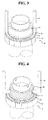
- FIG. 4 is a perspective view showing a coupling of a jig and a rotor for a torque sensor according to another embodiment of the present invention.
- a jig 51 comes into contact with the side surface of the sleeve 40.
- a diagonal line-shaped knurled portion 43 is formed on the side surface of the sleeve 40.
- the knurled portion 43 increases a frictional force at a contact portion between the sleeve 40 and the jig 51, thus allowing a rotating force to be precisely transmitted.
- the knurled portion 43 may be replaced by a hole 42 or a protrusion.
- the jig comprises two long bars.
- the jig may be selected from various shapes including one bar and a ring, as long as it may transmit a rotating force to the rotor and adjusts the center.
- the present invention provides various structures for precisely transmitting a rotating force by increasing a frictional force at a portion coupled with a jig when a center of a rotor of a torque sensor is adjusted.
- a fine adjustment of the torque center is possible. This improves operational reliability of a steering system.
Landscapes
- Physics & Mathematics (AREA)
- General Physics & Mathematics (AREA)
- Electromagnetism (AREA)
- Engineering & Computer Science (AREA)
- Chemical & Material Sciences (AREA)
- Combustion & Propulsion (AREA)
- Transportation (AREA)
- Mechanical Engineering (AREA)
- Power Steering Mechanism (AREA)
- Force Measurement Appropriate To Specific Purposes (AREA)
- Transmission And Conversion Of Sensor Element Output (AREA)
Abstract
Description
- The present invention relates generally to a rotor for a torque sensor and, more particularly, to a rotor for a torque sensor, configured to improve a mechanical coupling force with respect to a jig in a process of adjusting a torque center, thus enabling a fine adjustment.
- Generally, a vehicle is configured to change a driving direction by manipuating a steering wheel connected to a wheel. However, if resistance between the wheel and a road is large or there is an obstacle to steering, a manipulation force is decreased, thus making it difficult to rapidly manipuate. In order to solve the problem, a power steering system has been used. Such a power steering system includes a power unit to manipulate the steering wheel, thus reducing a manipuation force.
- In order for the power unit to assist in manipuating the steering wheel, it is necessary to measure torque acting on a steering shaft. Thus, several types of devices are used to measure torque of the steering wheel. Among them, a device detecting torque by measuring a magnetic field relative to a magnet coupled to the steering shaft has been widely used because it is more economical.
- A general steering structure includes an input shaft to which a steering wheel is coupled, an output shaft coupled to a pinion engaging with a rack bar of a wheel, and a torsion bar connecting the input shaft and the output shaft.
- If the steering wheel rotates, a rotating force is transmitted to the output shaft, and the wheel changes its direction by interaction between the pinion and the rack bar. Here, the larger resistance is, the more the input shaft rotates. Hence, the torsion bar is twisted. A degree to which the torsion bar is twisted is measured by the torque sensor using the magnetic field.
- When the steering wheel is not manipulated, the torque sensor maintains a central position. If a set center is erroneous, there occurs a difference in auxiliary steering force between left and right sides during a manipuation of the steering wheel. Thus, as for the power steering system, it is very important to adjust the center of the torque sensor.
-
FIG. 1 is a perspective view showing a conventional rotor for a torque sensor. - A rotor 1 having a
magnet 2 is coupled to an input shaft of a steering system, and a stator (not shown) is coupled to an output shaft. - If the torsion bar is twisted by a difference in rotation amount between the input shaft coupled to the rotor 1 and the output shaft coupled to the stator, the
magnet 2 and the stator rotate relative to each other. At this time, opposite surfaces between themagnet 2 and the stator are changed, so that a magnetization value is changed, and thereby torque may be measured using the change in magnetization value. - The rotor 1 includes a sleeve 4 coupled to an outer circumference of the input shaft, and a yoke 3 coupled with the sleeve 4 to allow the
magnet 2 to be coupled to an outer circumference thereof. - In order to adjust the center of the torque sensor, there has been used a method of holding a predetermined portion on the outer circumference of the sleeve 4 by a jig and then rotating the rotor 1 by a frictional force.
- However, such a method is problematic in that the jig rotates the outer circumference of the sleeve by the frictional force, so that there is a relatively strong possibility that the jig will slip from the sleeve, and it is difficult to finely adjust the center.
-
Document DE 10 2009 039082 discloses a magnet assembly in which the magnetic ring is radially connected to the sleeve with domes arranged on the circumference of the magnet ring and apertures on the sleeve adapted in geometry and number for producing a riveting lock system. - Accordingly, the present invention has been made keeping in mind the above problems occurring in the prior art, and an object of the present invention is to provide a rotor for a torque sensor, capable of more precisely performing a center adjusting operation.
- According to one aspect of this invention, there is provided a rotor for a torque sensor, the rotor comprising: a rotor body including a sleeve coupled to a rotating shaft, and a yoke protruding from an outer circumference of the sleeve; a ring-shaped magnet coupled to an outer circumference of the yoke; and an anti-slip structure formed on the rotor body and partially coming into contact with a jig during a rotating process for adjusting a torque center, thus preventing slipping between the rotor body and the jig when a rotating force is transmitted. Thus, slipping between the jig and the rotor body is prevented to enable precise transmission of the rotating force, so that accuracy is improved during fine adjustment of the torque center.
- Further, the anti-slip structure may include a serration formed on an upper end of the yoke in a circumferential direction thereof, the serration coming into contact with a lower end of the jig during the rotating process for adjusting the center, thus transmitting the rotating force from the jig to the yoke. Thus, the jig is brought into contact with the yoke, thus allowing the rotating force to be reliably transmitted when the center is adjusted.
- Further, the anti-slip structure may include a hole formed in the outer circumference of the sleeve, and a protrusion formed on the jig is inserted into the hole, thus transmitting the rotating force from the jig to the sleeve. Thus, the jig comes into contact with the sleeve, thus allowing the rotating force to be more reliably transmitted when the center is adjusted.
- Further, the anti-slip structure may include a knurled portion formed on the outer circumference of the sleeve, and the jig partially comes into contact with the knurled portion of the sleeve, thus transmitting the rotating force from the jig to the sleeve. Thus, a frictional force between the sleeve and the jig is improved, thus allowing the rotating force to be reliably transmitted.
- Further, the anti-slip structure may include a depression formed downwards from an upper end of the sleeve, and a protrusion formed on the jig is inserted into the depression, thus transmitting the rotating force from the jig to the sleeve. Thus, a mechanical coupling force between the sleeve and the jig is excellent.
- Meanwhile, according to another aspect of this invention, there is provided a rotor for a torque sensor, the rotor comprising: a rotor body coupled to a rotating shaft; a ring-shaped magnet disposed to protrude to an outer circumference of the rotor body; and an anti-slip structure formed on the rotor body, wherein during a rotating process for adjusting a torque center, a jig comes into contact with the outer circumference of the rotor body or an upper portion of the magnet, and the anti-slip structure is formed on a surface making contact with the jig, thus preventing slipping between the jig and the rotor body. Thus, a frictional force between contact portions of the jig and the rotor is improved, so that the accuracy of a center adjustment is improved.
- A rotor for a torque sensor according to the present invention constructed as described above is advantageous in that a frictional force is increased at a portion coupled with a jig when a center of the rotor is adjusted, thus providing various structures that enable precise transmission of a rotating force, and thereby permitting a fine adjustment of the torque center, therefore improving operational reliability of a steering system.
-
-
FIG. 1 is a perspective view showing a conventional rotor for a torque sensor; -
FIG. 2 is a perspective view showing a rotor for a torque sensor according to the present invention; -
FIG. 3 is a perspective view showing a coupling of a jig and a rotor for a torque sensor according to an embodiment of the present invention; and -
FIG. 4 is a perspective view showing a coupling of a jig and a rotor for a torque sensor according to another embodiment of the present invention. - Hereinafter, a rotor for a torque sensor according to the preferred embodiment of the present invention will be described in detail with reference to the accompanying drawings.
-
FIG. 2 is a perspective view showing a rotor for a torque sensor according to the present invention. - A
magnet 20 is shaped like a ring, and is generally coupled to an outer circumference of an input shaft of a steering system to be rotated along with the input shaft. - Further, a stator (not shown) is connected to an output shaft to be rotated along with the output shaft.
- It can be understood that torsion occurs when there is a difference in rotation amount between the input shaft and the output shaft due to resistance of a wheel. The difference is measured using a magnetic field as described above. Of course, the
magnet 20 may be connected to the output shaft, and the stator may be connected to the input shaft. - The
rotor 10 includes a rotor body and the ring-shaped magnet 20. The rotor body includes a ring-shaped yoke 30 that protrudes outwards from a lower end of asleeve 40 taking a shape of a hollow cylinder. Themagnet 20 is coupled to an outer circumference of the rotor body. To be more specific, themagnet 20 is coupled to an outer circumference of theyoke 30. - As described above, an inner circumference of the
sleeve 40 is connected to a rotating shaft of the steering system to be rotated along with the rotating shaft. - Further, the
yoke 30 is coupled to thesleeve 40 to support themagnet 20 and thereby rotate along with thesleeve 40. However, theyoke 30 may be integrated with thesleeve 40. - Preferably, the
magnet 20 comprises two or more magnet segments that are to be connected to each other. To be more specific, a plurality of arc-shaped magnet segments forms the ring-shaped magnet 20. - The
rotor 10 is coupled to the rotating shaft of the steering system by fitting therotor 10 over the rotating shaft starting from a lower portion of thesleeve 40, and a torque center is adjusted by an additional device, a jig. - According to the present invention, the rotor body has a shape to allow rotating power to be reliably transmitted between the jig and the
rotor 10, thus preventing slipping between the rotor body and the jig when the torque center is adjusted, and thereby enabling a precise adjustment. Such a shape may be implemented by various embodiments of anti-slip structures, for example, a structure for increasing a frictional force between contact portions, such as a serration or a micro groove, or a structure for providing a mechanical coupling force, such as a hole or a recess. - Thus, as a first embodiment for increasing a rotating frictional force, a
serrated portion 31 is formed on an upper end of theyoke 30. - The
serrated portion 31 is circumferentially formed on an upper surface of theyoke 30 protruding outwards from a lower end of thesleeve 40, thus having an uneven shape. It is preferable that the uneven shape be a wedge shape to allow theserrated portion 31 to be easily coupled to the jig. - In this case, a lower end of the jig is brought into contact with an upper end of the uneven
serrated portion 31 to transmit a rotating force. - Further, as a second embodiment for increasing a frictional force, an uneven portion may be formed on the upper surface of the
yoke 30. - The uneven portion may be formed by fine line-shaped grooves, or may comprise a single protrusion or a plurality of protrusions. In an example of
FIG. 4 , the uneven portion is formed by a plurality of diagonal line-shaped grooves. - Similarly to the first embodiment, the second embodiment provides a frictional force when a lower end of a jig comes into contact with the upper surface of the
yoke 30. - Further, as a third embodiment for increasing a frictional force, a
hole 42 is formed in a side surface of thesleeve 40. - Preferably, the
hole 42 is formed in the side surface of thesleeve 40 making contact with the jig, and a protrusion is formed on a portion of the jig to be fixedly inserted into thehole 42. - According to a shape of the jig, a single hole or a plurality of holes may be formed in the side surface of the
sleeve 40. - Meanwhile, the
hole 42 may be replaced by a recess, a fine line-shaped groove, a single protrusion or a plurality of protrusions. - Further, as a fourth embodiment for increasing a frictional force, a depression may be formed in an upper end of the
sleeve 40. - The depression is depressed downwards from the upper end of the
sleeve 40. In this case, the jig comes into contact with the upper end of thesleeve 40 and includes a protrusion that may be inserted into the depression, thus maximizing a frictional force therebetween. - The above embodiments for increasing the frictional force may be selectively applied, but two or more embodiments may combine with each other.
- For example, both the
serrated portion 31 of theyoke 30 and thehole 42 of thesleeve 40 may be formed, and the jig may be disposed to be in contact with both the upper surface of theyoke 30 and the side surface of thesleeve 40. In this case, since a frictional force between contact surfaces of therotor 10 and the jig is maximized, a center adjusting operation can be precisely performed. -
FIG. 3 is a perspective view showing a coupling of a jig and a rotor for a torque sensor according to an embodiment of the present invention. - While the torque center of the rotor for the torque sensor is adjusted, the lower end of the
jig 50 comes into contact with the upper surface of theyoke 30 in a state in which therotor 10 is coupled to an outer circumference of the rotating shaft. - Since the
serrated portion 31 is formed on the upper surface of theyoke 30 and a serrated portion is also formed on the lower end of thejig 50 to correspond to a shape of theserrated portion 31, a rotating force can be precisely transmitted between theyoke 30 and thejig 50. -
FIG. 4 is a perspective view showing a coupling of a jig and a rotor for a torque sensor according to another embodiment of the present invention. - Unlike the embodiment of
FIG. 3 , a jig 51comes into contact with the side surface of thesleeve 40. - A diagonal line-shaped
knurled portion 43 is formed on the side surface of thesleeve 40. Theknurled portion 43 increases a frictional force at a contact portion between thesleeve 40 and thejig 51, thus allowing a rotating force to be precisely transmitted. - Of course, as described above, the
knurled portion 43 may be replaced by ahole 42 or a protrusion. - According to the above embodiment, the jig comprises two long bars. However, the jig may be selected from various shapes including one bar and a ring, as long as it may transmit a rotating force to the rotor and adjusts the center.
- The present invention provides various structures for precisely transmitting a rotating force by increasing a frictional force at a portion coupled with a jig when a center of a rotor of a torque sensor is adjusted. Thus, a fine adjustment of the torque center is possible. This improves operational reliability of a steering system.
- The present invention has been described with reference to embodiments and the accompanying drawings. However, it is to be understood that the scope of the invention is not limited by the specific embodiments and drawings except as defined in the appended claims.
Claims (2)
- A rotor for a torque sensor, comprising:a rotor body (10) comprising a sleeve (40) having a first outer circumference and a yoke (30) having a second outer circumference,a magnet (20) provided around the second outer circumference of the yoke (30),a serrated portion (31) having a plurality of serrations arranged in a circumferential direction of the rotor body (10), wherein each of the plurality of serrations extends in a radial direction of the rotor body and wherein the serrated portion (31) is formed on an upper end of the yoke (30).
- The rotor as set forth in claim 1, wherein the serrated portion (31) comes into contact with a lower end of a jig (50) during the rotating process for adjusting the center, thus transmitting the rotating force from the jig to the yoke.
Applications Claiming Priority (2)
| Application Number | Priority Date | Filing Date | Title |
|---|---|---|---|
| KR1020110038654A KR101872897B1 (en) | 2011-04-25 | 2011-04-25 | Rotor for torque sensor and torque sensor including the same |
| EP12165570.8A EP2518463B1 (en) | 2011-04-25 | 2012-04-25 | Rotor for torque sensor |
Related Parent Applications (2)
| Application Number | Title | Priority Date | Filing Date |
|---|---|---|---|
| EP12165570.8A Division-Into EP2518463B1 (en) | 2011-04-25 | 2012-04-25 | Rotor for torque sensor |
| EP12165570.8A Division EP2518463B1 (en) | 2011-04-25 | 2012-04-25 | Rotor for torque sensor |
Publications (2)
| Publication Number | Publication Date |
|---|---|
| EP3035023A1 true EP3035023A1 (en) | 2016-06-22 |
| EP3035023B1 EP3035023B1 (en) | 2019-11-06 |
Family
ID=46022114
Family Applications (2)
| Application Number | Title | Priority Date | Filing Date |
|---|---|---|---|
| EP16153516.6A Active EP3035023B1 (en) | 2011-04-25 | 2012-04-25 | Rotor for torque sensor |
| EP12165570.8A Active EP2518463B1 (en) | 2011-04-25 | 2012-04-25 | Rotor for torque sensor |
Family Applications After (1)
| Application Number | Title | Priority Date | Filing Date |
|---|---|---|---|
| EP12165570.8A Active EP2518463B1 (en) | 2011-04-25 | 2012-04-25 | Rotor for torque sensor |
Country Status (5)
| Country | Link |
|---|---|
| US (5) | US8584532B2 (en) |
| EP (2) | EP3035023B1 (en) |
| JP (2) | JP6042630B2 (en) |
| KR (1) | KR101872897B1 (en) |
| CN (1) | CN102759424B (en) |
Families Citing this family (12)
| Publication number | Priority date | Publication date | Assignee | Title |
|---|---|---|---|---|
| KR101872897B1 (en) * | 2011-04-25 | 2018-06-29 | 엘지이노텍 주식회사 | Rotor for torque sensor and torque sensor including the same |
| KR102288523B1 (en) * | 2014-12-30 | 2021-08-11 | 엘지이노텍 주식회사 | Torque angle sensor module and apparatus for sensing steering angle of vehicle using the same |
| DE102015106933A1 (en) * | 2015-05-04 | 2016-11-10 | Technische Universität Darmstadt | Machine element with a sensor device and method for producing a machine element |
| KR102385207B1 (en) * | 2015-08-20 | 2022-04-11 | 엘지이노텍 주식회사 | Rotor, torque sensor and electronic power steering system including the same |
| US9810592B2 (en) * | 2015-08-20 | 2017-11-07 | Lg Innotek Co., Ltd. | Rotor, and torque sensor and electronic power steering system including the same |
| KR102224462B1 (en) * | 2016-04-29 | 2021-03-08 | 엘지이노텍 주식회사 | Rotor, torque sensor and electronic power steering system including the same |
| KR102620900B1 (en) * | 2016-01-07 | 2024-01-05 | 엘지이노텍 주식회사 | Rotor, torque sensor and electronic power steering system including the same |
| DE102016110774A1 (en) * | 2016-06-13 | 2017-12-14 | Valeo Schalter Und Sensoren Gmbh | Magnet unit for a sensor device of a motor vehicle, sensor device with a magnet unit and motor vehicle with a sensor device |
| KR102748916B1 (en) * | 2016-06-24 | 2025-01-02 | 엘지이노텍 주식회사 | Apparatus for sensing and apparatus for steering |
| KR102656078B1 (en) * | 2016-07-19 | 2024-04-11 | 엘지이노텍 주식회사 | Apparatus for sensing |
| KR20190061257A (en) | 2017-11-27 | 2019-06-05 | 이동원 | Assembly which includes Pressure/temperature sensor for heat pump |
| CN113607324B (en) * | 2021-08-06 | 2023-02-28 | 常州市蓝光电子有限公司 | Torsion tester |
Citations (2)
| Publication number | Priority date | Publication date | Assignee | Title |
|---|---|---|---|---|
| WO2008026200A2 (en) * | 2006-08-31 | 2008-03-06 | Rafael Advanced Defense Systems Ltd. | An adaptor for a torque transducer |
| DE102009039082A1 (en) | 2009-08-27 | 2011-03-03 | Valeo Schalter Und Sensoren Gmbh | Magnet assembly for a torque and / or rotation angle sensor assembly with a magnetic ring and manufacturing method |
Family Cites Families (28)
| Publication number | Priority date | Publication date | Assignee | Title |
|---|---|---|---|---|
| US4629982A (en) | 1983-07-01 | 1986-12-16 | Transducer Systems, Inc. | Apparatus for detecting motion and direction using magnetoresistive sensors producing sum and difference signals |
| FR2670888B1 (en) | 1990-12-19 | 1994-05-27 | Aerospatiale | ANGULAR POSITION SENSOR WITH MAGNETORESISTANCES. |
| US5197338A (en) * | 1991-07-22 | 1993-03-30 | Liberty Technology Center, Inc. | System and method for determining torque output of motor actuated valve operators |
| JPH07243864A (en) * | 1994-03-03 | 1995-09-19 | Daido Steel Co Ltd | Magnetic rotor for tachometer |
| JPH10119796A (en) * | 1996-10-24 | 1998-05-12 | Honda Motor Co Ltd | Electric power steering device |
| SG94323A1 (en) | 1998-04-20 | 2003-02-18 | Canon Kk | Motor |
| JP3514426B2 (en) * | 1998-05-25 | 2004-03-31 | ヤマウチ株式会社 | Torque limiter |
| JP3781951B2 (en) * | 2000-07-14 | 2006-06-07 | 株式会社日立製作所 | Torque sensor reference position adjustment method |
| FR2824910B1 (en) | 2001-05-18 | 2005-05-13 | Denso Corp | TORQUE SENSOR AND POWER ASSISTED STEERING SYSTEM EMPLOYING THIS SENSOR |
| JP3886434B2 (en) | 2001-10-15 | 2007-02-28 | 株式会社デンソー | Torque sensor assembly method |
| JP2003185510A (en) * | 2001-12-14 | 2003-07-03 | Unisia Jkc Steering System Co Ltd | Torque sensor |
| JP2004163303A (en) | 2002-11-14 | 2004-06-10 | Denso Corp | Torque sensor |
| JP2005037177A (en) | 2003-07-17 | 2005-02-10 | Unisia Jkc Steering System Co Ltd | Torque sensor and torque sensor fixing method |
| JP2005069994A (en) | 2003-08-27 | 2005-03-17 | Koyo Seiko Co Ltd | Device for detecting torque |
| JP4518818B2 (en) | 2004-03-17 | 2010-08-04 | 三菱電機株式会社 | Torque sensor |
| JP2006030088A (en) | 2004-07-20 | 2006-02-02 | Hitachi Ltd | Torque sensor and assembling method thereof |
| DE102005018293B4 (en) | 2005-04-15 | 2024-05-08 | Valeo Schalter Und Sensoren Gmbh | Device for determining a torque exerted on a shaft |
| GB2426591B (en) * | 2005-05-27 | 2009-12-30 | Tt Electronics Technology Ltd | Sensing apparatus and method |
| JP4871014B2 (en) * | 2006-04-24 | 2012-02-08 | カヤバ工業株式会社 | Torque sensor |
| JP5440754B2 (en) | 2008-04-10 | 2014-03-12 | 日本精工株式会社 | Torque detector, electric power steering apparatus, and method of manufacturing torque detector |
| JP2010017839A (en) * | 2008-07-14 | 2010-01-28 | Yasuhiro Yamaguchi | Holding type vehicle height adjustment tool |
| KR100951425B1 (en) | 2008-09-25 | 2010-04-07 | 뉴모텍(주) | Fan motor for refrigerator |
| KR101208178B1 (en) * | 2008-10-06 | 2012-12-04 | 주식회사 만도 | Electronic power steering apparatus having torque sensor |
| KR100989684B1 (en) | 2009-01-19 | 2010-10-26 | 뉴모텍(주) | Axial type motor |
| KR101279774B1 (en) * | 2009-03-30 | 2013-07-04 | 주식회사 만도 | Torque Rotor and Manufacturing Method of The Same |
| KR101047475B1 (en) * | 2009-05-08 | 2011-07-08 | 엘지이노텍 주식회사 | Spindle motor |
| CN101949750B (en) * | 2010-08-31 | 2012-05-09 | 杭州飞越汽车零部件有限公司 | Automobile steering torque measuring device and method for measuring automobile steering torque |
| KR101872897B1 (en) * | 2011-04-25 | 2018-06-29 | 엘지이노텍 주식회사 | Rotor for torque sensor and torque sensor including the same |
-
2011
- 2011-04-25 KR KR1020110038654A patent/KR101872897B1/en active Active
-
2012
- 2012-04-24 CN CN201210123524.0A patent/CN102759424B/en active Active
- 2012-04-25 JP JP2012100442A patent/JP6042630B2/en active Active
- 2012-04-25 EP EP16153516.6A patent/EP3035023B1/en active Active
- 2012-04-25 EP EP12165570.8A patent/EP2518463B1/en active Active
- 2012-04-25 US US13/455,591 patent/US8584532B2/en active Active
-
2013
- 2013-06-21 US US13/923,865 patent/US8776618B2/en active Active
-
2014
- 2014-05-16 US US14/280,367 patent/US9121783B2/en active Active
-
2015
- 2015-07-28 US US14/811,008 patent/US9551622B2/en active Active
-
2016
- 2016-03-09 US US15/065,049 patent/US9903773B2/en active Active
- 2016-05-09 JP JP2016093970A patent/JP6313364B2/en active Active
Patent Citations (2)
| Publication number | Priority date | Publication date | Assignee | Title |
|---|---|---|---|---|
| WO2008026200A2 (en) * | 2006-08-31 | 2008-03-06 | Rafael Advanced Defense Systems Ltd. | An adaptor for a torque transducer |
| DE102009039082A1 (en) | 2009-08-27 | 2011-03-03 | Valeo Schalter Und Sensoren Gmbh | Magnet assembly for a torque and / or rotation angle sensor assembly with a magnetic ring and manufacturing method |
Also Published As
| Publication number | Publication date |
|---|---|
| CN102759424A (en) | 2012-10-31 |
| US9551622B2 (en) | 2017-01-24 |
| JP2012230108A (en) | 2012-11-22 |
| US20130276551A1 (en) | 2013-10-24 |
| JP6313364B2 (en) | 2018-04-18 |
| JP2016148680A (en) | 2016-08-18 |
| EP2518463A3 (en) | 2015-09-30 |
| US20160187212A1 (en) | 2016-06-30 |
| KR20120120852A (en) | 2012-11-02 |
| EP2518463B1 (en) | 2018-02-28 |
| EP3035023B1 (en) | 2019-11-06 |
| US20120266695A1 (en) | 2012-10-25 |
| EP2518463A2 (en) | 2012-10-31 |
| CN102759424B (en) | 2015-04-29 |
| US8584532B2 (en) | 2013-11-19 |
| US9903773B2 (en) | 2018-02-27 |
| US20150330850A1 (en) | 2015-11-19 |
| US8776618B2 (en) | 2014-07-15 |
| KR101872897B1 (en) | 2018-06-29 |
| JP6042630B2 (en) | 2016-12-14 |
| US9121783B2 (en) | 2015-09-01 |
| US20140251028A1 (en) | 2014-09-11 |
Similar Documents
| Publication | Publication Date | Title |
|---|---|---|
| EP3035023B1 (en) | Rotor for torque sensor | |
| US7954389B2 (en) | Torque sensor and manufacturing method thereof | |
| KR101279774B1 (en) | Torque Rotor and Manufacturing Method of The Same | |
| EP3081456B1 (en) | Vehicular steering system | |
| US9765823B2 (en) | Steering apparatus | |
| EP2644476A2 (en) | Torque detection device, and electric power steering system including the torque detection device | |
| JP5656016B2 (en) | Vehicle steering control device | |
| JP5871151B2 (en) | Yoke assembly manufacturing method | |
| KR20090128859A (en) | Combined structure of torque sensor and steering shaft | |
| JP5338180B2 (en) | Electric power steering device | |
| EP3489630B1 (en) | Sensor device | |
| JP5467808B2 (en) | Rotor shaft | |
| EP3623667A1 (en) | A transmission | |
| KR102463425B1 (en) | Steering system having improved torque sensor mounting structure | |
| JP2001158368A (en) | Electric power steering device | |
| JP2011099831A (en) | Structure for fixing torque measurement device for power steering device | |
| KR20170087657A (en) | Steering Column for Vehicle | |
| KR101047389B1 (en) | Caleb Type Electric Power Steering Device | |
| JP2001158367A (en) | Electric power steering device | |
| JP2010208448A (en) | Steering angle detecting device of steer-by-wire type steering |
Legal Events
| Date | Code | Title | Description |
|---|---|---|---|
| PUAI | Public reference made under article 153(3) epc to a published international application that has entered the european phase |
Free format text: ORIGINAL CODE: 0009012 |
|
| AC | Divisional application: reference to earlier application |
Ref document number: 2518463 Country of ref document: EP Kind code of ref document: P |
|
| AK | Designated contracting states |
Kind code of ref document: A1 Designated state(s): AL AT BE BG CH CY CZ DE DK EE ES FI FR GB GR HR HU IE IS IT LI LT LU LV MC MK MT NL NO PL PT RO RS SE SI SK SM TR |
|
| AX | Request for extension of the european patent |
Extension state: BA ME |
|
| STAA | Information on the status of an ep patent application or granted ep patent |
Free format text: STATUS: REQUEST FOR EXAMINATION WAS MADE |
|
| 17P | Request for examination filed |
Effective date: 20161220 |
|
| RBV | Designated contracting states (corrected) |
Designated state(s): AL AT BE BG CH CY CZ DE DK EE ES FI FR GB GR HR HU IE IS IT LI LT LU LV MC MK MT NL NO PL PT RO RS SE SI SK SM TR |
|
| RAP1 | Party data changed (applicant data changed or rights of an application transferred) |
Owner name: LG INNOTEK CO., LTD. |
|
| STAA | Information on the status of an ep patent application or granted ep patent |
Free format text: STATUS: EXAMINATION IS IN PROGRESS |
|
| 17Q | First examination report despatched |
Effective date: 20180601 |
|
| GRAP | Despatch of communication of intention to grant a patent |
Free format text: ORIGINAL CODE: EPIDOSNIGR1 |
|
| STAA | Information on the status of an ep patent application or granted ep patent |
Free format text: STATUS: GRANT OF PATENT IS INTENDED |
|
| INTG | Intention to grant announced |
Effective date: 20190619 |
|
| GRAS | Grant fee paid |
Free format text: ORIGINAL CODE: EPIDOSNIGR3 |
|
| GRAA | (expected) grant |
Free format text: ORIGINAL CODE: 0009210 |
|
| STAA | Information on the status of an ep patent application or granted ep patent |
Free format text: STATUS: THE PATENT HAS BEEN GRANTED |
|
| AC | Divisional application: reference to earlier application |
Ref document number: 2518463 Country of ref document: EP Kind code of ref document: P |
|
| AK | Designated contracting states |
Kind code of ref document: B1 Designated state(s): AL AT BE BG CH CY CZ DE DK EE ES FI FR GB GR HR HU IE IS IT LI LT LU LV MC MK MT NL NO PL PT RO RS SE SI SK SM TR |
|
| REG | Reference to a national code |
Ref country code: GB Ref legal event code: FG4D |
|
| REG | Reference to a national code |
Ref country code: CH Ref legal event code: EP Ref country code: AT Ref legal event code: REF Ref document number: 1199392 Country of ref document: AT Kind code of ref document: T Effective date: 20191115 |
|
| REG | Reference to a national code |
Ref country code: IE Ref legal event code: FG4D |
|
| REG | Reference to a national code |
Ref country code: DE Ref legal event code: R096 Ref document number: 602012065556 Country of ref document: DE |
|
| REG | Reference to a national code |
Ref country code: NL Ref legal event code: MP Effective date: 20191106 |
|
| REG | Reference to a national code |
Ref country code: LT Ref legal event code: MG4D |
|
| PG25 | Lapsed in a contracting state [announced via postgrant information from national office to epo] |
Ref country code: BG Free format text: LAPSE BECAUSE OF FAILURE TO SUBMIT A TRANSLATION OF THE DESCRIPTION OR TO PAY THE FEE WITHIN THE PRESCRIBED TIME-LIMIT Effective date: 20200206 Ref country code: FI Free format text: LAPSE BECAUSE OF FAILURE TO SUBMIT A TRANSLATION OF THE DESCRIPTION OR TO PAY THE FEE WITHIN THE PRESCRIBED TIME-LIMIT Effective date: 20191106 Ref country code: PT Free format text: LAPSE BECAUSE OF FAILURE TO SUBMIT A TRANSLATION OF THE DESCRIPTION OR TO PAY THE FEE WITHIN THE PRESCRIBED TIME-LIMIT Effective date: 20200306 Ref country code: LV Free format text: LAPSE BECAUSE OF FAILURE TO SUBMIT A TRANSLATION OF THE DESCRIPTION OR TO PAY THE FEE WITHIN THE PRESCRIBED TIME-LIMIT Effective date: 20191106 Ref country code: SE Free format text: LAPSE BECAUSE OF FAILURE TO SUBMIT A TRANSLATION OF THE DESCRIPTION OR TO PAY THE FEE WITHIN THE PRESCRIBED TIME-LIMIT Effective date: 20191106 Ref country code: PL Free format text: LAPSE BECAUSE OF FAILURE TO SUBMIT A TRANSLATION OF THE DESCRIPTION OR TO PAY THE FEE WITHIN THE PRESCRIBED TIME-LIMIT Effective date: 20191106 Ref country code: LT Free format text: LAPSE BECAUSE OF FAILURE TO SUBMIT A TRANSLATION OF THE DESCRIPTION OR TO PAY THE FEE WITHIN THE PRESCRIBED TIME-LIMIT Effective date: 20191106 Ref country code: NO Free format text: LAPSE BECAUSE OF FAILURE TO SUBMIT A TRANSLATION OF THE DESCRIPTION OR TO PAY THE FEE WITHIN THE PRESCRIBED TIME-LIMIT Effective date: 20200206 Ref country code: GR Free format text: LAPSE BECAUSE OF FAILURE TO SUBMIT A TRANSLATION OF THE DESCRIPTION OR TO PAY THE FEE WITHIN THE PRESCRIBED TIME-LIMIT Effective date: 20200207 Ref country code: NL Free format text: LAPSE BECAUSE OF FAILURE TO SUBMIT A TRANSLATION OF THE DESCRIPTION OR TO PAY THE FEE WITHIN THE PRESCRIBED TIME-LIMIT Effective date: 20191106 |
|
| PG25 | Lapsed in a contracting state [announced via postgrant information from national office to epo] |
Ref country code: HR Free format text: LAPSE BECAUSE OF FAILURE TO SUBMIT A TRANSLATION OF THE DESCRIPTION OR TO PAY THE FEE WITHIN THE PRESCRIBED TIME-LIMIT Effective date: 20191106 Ref country code: IS Free format text: LAPSE BECAUSE OF FAILURE TO SUBMIT A TRANSLATION OF THE DESCRIPTION OR TO PAY THE FEE WITHIN THE PRESCRIBED TIME-LIMIT Effective date: 20200306 Ref country code: RS Free format text: LAPSE BECAUSE OF FAILURE TO SUBMIT A TRANSLATION OF THE DESCRIPTION OR TO PAY THE FEE WITHIN THE PRESCRIBED TIME-LIMIT Effective date: 20191106 |
|
| PG25 | Lapsed in a contracting state [announced via postgrant information from national office to epo] |
Ref country code: AL Free format text: LAPSE BECAUSE OF FAILURE TO SUBMIT A TRANSLATION OF THE DESCRIPTION OR TO PAY THE FEE WITHIN THE PRESCRIBED TIME-LIMIT Effective date: 20191106 |
|
| PG25 | Lapsed in a contracting state [announced via postgrant information from national office to epo] |
Ref country code: EE Free format text: LAPSE BECAUSE OF FAILURE TO SUBMIT A TRANSLATION OF THE DESCRIPTION OR TO PAY THE FEE WITHIN THE PRESCRIBED TIME-LIMIT Effective date: 20191106 Ref country code: DK Free format text: LAPSE BECAUSE OF FAILURE TO SUBMIT A TRANSLATION OF THE DESCRIPTION OR TO PAY THE FEE WITHIN THE PRESCRIBED TIME-LIMIT Effective date: 20191106 Ref country code: RO Free format text: LAPSE BECAUSE OF FAILURE TO SUBMIT A TRANSLATION OF THE DESCRIPTION OR TO PAY THE FEE WITHIN THE PRESCRIBED TIME-LIMIT Effective date: 20191106 Ref country code: CZ Free format text: LAPSE BECAUSE OF FAILURE TO SUBMIT A TRANSLATION OF THE DESCRIPTION OR TO PAY THE FEE WITHIN THE PRESCRIBED TIME-LIMIT Effective date: 20191106 Ref country code: ES Free format text: LAPSE BECAUSE OF FAILURE TO SUBMIT A TRANSLATION OF THE DESCRIPTION OR TO PAY THE FEE WITHIN THE PRESCRIBED TIME-LIMIT Effective date: 20191106 |
|
| REG | Reference to a national code |
Ref country code: DE Ref legal event code: R097 Ref document number: 602012065556 Country of ref document: DE |
|
| REG | Reference to a national code |
Ref country code: AT Ref legal event code: MK05 Ref document number: 1199392 Country of ref document: AT Kind code of ref document: T Effective date: 20191106 |
|
| PG25 | Lapsed in a contracting state [announced via postgrant information from national office to epo] |
Ref country code: SM Free format text: LAPSE BECAUSE OF FAILURE TO SUBMIT A TRANSLATION OF THE DESCRIPTION OR TO PAY THE FEE WITHIN THE PRESCRIBED TIME-LIMIT Effective date: 20191106 Ref country code: SK Free format text: LAPSE BECAUSE OF FAILURE TO SUBMIT A TRANSLATION OF THE DESCRIPTION OR TO PAY THE FEE WITHIN THE PRESCRIBED TIME-LIMIT Effective date: 20191106 |
|
| PLBE | No opposition filed within time limit |
Free format text: ORIGINAL CODE: 0009261 |
|
| STAA | Information on the status of an ep patent application or granted ep patent |
Free format text: STATUS: NO OPPOSITION FILED WITHIN TIME LIMIT |
|
| 26N | No opposition filed |
Effective date: 20200807 |
|
| PG25 | Lapsed in a contracting state [announced via postgrant information from national office to epo] |
Ref country code: AT Free format text: LAPSE BECAUSE OF FAILURE TO SUBMIT A TRANSLATION OF THE DESCRIPTION OR TO PAY THE FEE WITHIN THE PRESCRIBED TIME-LIMIT Effective date: 20191106 Ref country code: MC Free format text: LAPSE BECAUSE OF FAILURE TO SUBMIT A TRANSLATION OF THE DESCRIPTION OR TO PAY THE FEE WITHIN THE PRESCRIBED TIME-LIMIT Effective date: 20191106 Ref country code: SI Free format text: LAPSE BECAUSE OF FAILURE TO SUBMIT A TRANSLATION OF THE DESCRIPTION OR TO PAY THE FEE WITHIN THE PRESCRIBED TIME-LIMIT Effective date: 20191106 |
|
| REG | Reference to a national code |
Ref country code: CH Ref legal event code: PL |
|
| PG25 | Lapsed in a contracting state [announced via postgrant information from national office to epo] |
Ref country code: LI Free format text: LAPSE BECAUSE OF NON-PAYMENT OF DUE FEES Effective date: 20200430 Ref country code: IT Free format text: LAPSE BECAUSE OF FAILURE TO SUBMIT A TRANSLATION OF THE DESCRIPTION OR TO PAY THE FEE WITHIN THE PRESCRIBED TIME-LIMIT Effective date: 20191106 Ref country code: LU Free format text: LAPSE BECAUSE OF NON-PAYMENT OF DUE FEES Effective date: 20200425 Ref country code: CH Free format text: LAPSE BECAUSE OF NON-PAYMENT OF DUE FEES Effective date: 20200430 |
|
| REG | Reference to a national code |
Ref country code: BE Ref legal event code: MM Effective date: 20200430 |
|
| PG25 | Lapsed in a contracting state [announced via postgrant information from national office to epo] |
Ref country code: BE Free format text: LAPSE BECAUSE OF NON-PAYMENT OF DUE FEES Effective date: 20200430 |
|
| GBPC | Gb: european patent ceased through non-payment of renewal fee |
Effective date: 20200425 |
|
| PG25 | Lapsed in a contracting state [announced via postgrant information from national office to epo] |
Ref country code: GB Free format text: LAPSE BECAUSE OF NON-PAYMENT OF DUE FEES Effective date: 20200425 Ref country code: IE Free format text: LAPSE BECAUSE OF NON-PAYMENT OF DUE FEES Effective date: 20200425 |
|
| PG25 | Lapsed in a contracting state [announced via postgrant information from national office to epo] |
Ref country code: TR Free format text: LAPSE BECAUSE OF FAILURE TO SUBMIT A TRANSLATION OF THE DESCRIPTION OR TO PAY THE FEE WITHIN THE PRESCRIBED TIME-LIMIT Effective date: 20191106 Ref country code: MT Free format text: LAPSE BECAUSE OF FAILURE TO SUBMIT A TRANSLATION OF THE DESCRIPTION OR TO PAY THE FEE WITHIN THE PRESCRIBED TIME-LIMIT Effective date: 20191106 Ref country code: CY Free format text: LAPSE BECAUSE OF FAILURE TO SUBMIT A TRANSLATION OF THE DESCRIPTION OR TO PAY THE FEE WITHIN THE PRESCRIBED TIME-LIMIT Effective date: 20191106 |
|
| PG25 | Lapsed in a contracting state [announced via postgrant information from national office to epo] |
Ref country code: MK Free format text: LAPSE BECAUSE OF FAILURE TO SUBMIT A TRANSLATION OF THE DESCRIPTION OR TO PAY THE FEE WITHIN THE PRESCRIBED TIME-LIMIT Effective date: 20191106 |
|
| PGFP | Annual fee paid to national office [announced via postgrant information from national office to epo] |
Ref country code: DE Payment date: 20250320 Year of fee payment: 14 |
|
| PGFP | Annual fee paid to national office [announced via postgrant information from national office to epo] |
Ref country code: FR Payment date: 20260323 Year of fee payment: 15 |