EP3035010A1 - Wetterdatenabhängige Füllstandsensorabfrage - Google Patents
Wetterdatenabhängige Füllstandsensorabfrage Download PDFInfo
- Publication number
- EP3035010A1 EP3035010A1 EP14198153.0A EP14198153A EP3035010A1 EP 3035010 A1 EP3035010 A1 EP 3035010A1 EP 14198153 A EP14198153 A EP 14198153A EP 3035010 A1 EP3035010 A1 EP 3035010A1
- Authority
- EP
- European Patent Office
- Prior art keywords
- measuring device
- meter
- distance
- time
- measuring
- Prior art date
- Legal status (The legal status is an assumption and is not a legal conclusion. Google has not performed a legal analysis and makes no representation as to the accuracy of the status listed.)
- Granted
Links
Images

Classifications
-
- G—PHYSICS
- G01—MEASURING; TESTING
- G01F—MEASURING VOLUME, VOLUME FLOW, MASS FLOW OR LIQUID LEVEL; METERING BY VOLUME
- G01F23/00—Indicating or measuring liquid level or level of fluent solid material, e.g. indicating in terms of volume or indicating by means of an alarm
- G01F23/80—Arrangements for signal processing
- G01F23/802—Particular electronic circuits for digital processing equipment
- G01F23/804—Particular electronic circuits for digital processing equipment containing circuits handling parameters other than liquid level
-
- G—PHYSICS
- G01—MEASURING; TESTING
- G01C—MEASURING DISTANCES, LEVELS OR BEARINGS; SURVEYING; NAVIGATION; GYROSCOPIC INSTRUMENTS; PHOTOGRAMMETRY OR VIDEOGRAMMETRY
- G01C13/00—Surveying specially adapted to open water, e.g. sea, lake, river or canal
- G01C13/008—Surveying specially adapted to open water, e.g. sea, lake, river or canal measuring depth of open water
-
- G—PHYSICS
- G01—MEASURING; TESTING
- G01F—MEASURING VOLUME, VOLUME FLOW, MASS FLOW OR LIQUID LEVEL; METERING BY VOLUME
- G01F23/00—Indicating or measuring liquid level or level of fluent solid material, e.g. indicating in terms of volume or indicating by means of an alarm
- G01F23/22—Indicating or measuring liquid level or level of fluent solid material, e.g. indicating in terms of volume or indicating by means of an alarm by measuring physical variables, other than linear dimensions, pressure or weight, dependent on the level to be measured, e.g. by difference of heat transfer of steam or water
- G01F23/28—Indicating or measuring liquid level or level of fluent solid material, e.g. indicating in terms of volume or indicating by means of an alarm by measuring physical variables, other than linear dimensions, pressure or weight, dependent on the level to be measured, e.g. by difference of heat transfer of steam or water by measuring the variations of parameters of electromagnetic or acoustic waves applied directly to the liquid or fluent solid material
- G01F23/284—Electromagnetic waves
-
- G—PHYSICS
- G01—MEASURING; TESTING
- G01F—MEASURING VOLUME, VOLUME FLOW, MASS FLOW OR LIQUID LEVEL; METERING BY VOLUME
- G01F23/00—Indicating or measuring liquid level or level of fluent solid material, e.g. indicating in terms of volume or indicating by means of an alarm
- G01F23/80—Arrangements for signal processing
- G01F23/802—Particular electronic circuits for digital processing equipment
-
- G—PHYSICS
- G01—MEASURING; TESTING
- G01W—METEOROLOGY
- G01W1/00—Meteorology
- G01W1/02—Instruments for indicating weather conditions by measuring two or more variables, e.g. humidity, pressure, temperature, cloud cover or wind speed
-
- G—PHYSICS
- G01—MEASURING; TESTING
- G01W—METEOROLOGY
- G01W1/00—Meteorology
- G01W1/10—Devices for predicting weather conditions
-
- G—PHYSICS
- G01—MEASURING; TESTING
- G01W—METEOROLOGY
- G01W2203/00—Real-time site-specific personalized weather information, e.g. nowcasting
-
- Y—GENERAL TAGGING OF NEW TECHNOLOGICAL DEVELOPMENTS; GENERAL TAGGING OF CROSS-SECTIONAL TECHNOLOGIES SPANNING OVER SEVERAL SECTIONS OF THE IPC; TECHNICAL SUBJECTS COVERED BY FORMER USPC CROSS-REFERENCE ART COLLECTIONS [XRACs] AND DIGESTS
- Y04—INFORMATION OR COMMUNICATION TECHNOLOGIES HAVING AN IMPACT ON OTHER TECHNOLOGY AREAS
- Y04S—SYSTEMS INTEGRATING TECHNOLOGIES RELATED TO POWER NETWORK OPERATION, COMMUNICATION OR INFORMATION TECHNOLOGIES FOR IMPROVING THE ELECTRICAL POWER GENERATION, TRANSMISSION, DISTRIBUTION, MANAGEMENT OR USAGE, i.e. SMART GRIDS
- Y04S20/00—Management or operation of end-user stationary applications or the last stages of power distribution; Controlling, monitoring or operating thereof
- Y04S20/30—Smart metering, e.g. specially adapted for remote reading
Definitions
- the invention relates to the distance and level measurement. More particularly, the invention relates to a meter assembly having a meter for measuring a distance to an object, a method of measuring a distance of a meter from an object, a program item, and a computer readable medium.
- Level measurements of flowing or standing water or other level or distance measurements such as snow depth measurement in the mountains, often measuring devices (sensors) are used with battery or battery power, as the power supply via a cable is usually not possible or at least not provided.
- a first aspect of the invention relates to a measuring device arrangement with a measuring device for measuring a distance to an object, for measuring a flow or a pressure.
- the measuring device arrangement can be, for example, a comprehensive measuring system, which has further devices in addition to the actual measuring device, like a control center or central office and a weather service.
- the measuring device is, for example, a fill level measuring device, a flow meter, a pressure gauge or a level measuring device for determining the fill level or the level of a medium, that is to say in particular a stagnant body of water, flowing water or snow.
- the measuring device can be a non-contact measuring device, for example a filling level radar, or else a non-contact measuring measuring device which, for example, uses a waveguide or a resonator which projects into the medium.
- the meter assembly includes one or more control units. At least one of these control units is configured to calculate a time for a next measurement of the distance, wherein the calculation of the time takes place taking into account a current and / or a forecasted weather information, which relates to the weather at the location of the meter.
- the control unit which calculates the time for the next measurement of the distance, can for example be integrated in the measuring device itself. However, it can also be provided that this control unit is integrated in another device, for example in a remote from the meter control center that communicatively connected to the meter (for example, via a radio interface).
- the control unit can also be integrated in a weather station or in a system to weather stations, in which case the weather station or the system is running at weather stations for communication with the meter and / or the control center to the current and / or forecast weather information to provide the meter or the control center.
- the weather station transmits the weather forecast to the control center and then calculates the appropriate time for a future distance measurement or even several suitable times for future distance measurements and transmitted to the meter.
- the required computing power in the meter can be reduced and at the same time the data transfer between the meter and the control center can be reduced.
- the control center the measuring device specifies a complete measurement cycle, which is to follow the next few days. It may be provided that the measuring device modifies this measuring cycle if, for example, they change the external circumstances or do not occur as predicted by the weather forecast.
- control unit also takes into account a history of past distance measurements carried out by the measuring device for calculating the time for the next measurement of the distance in addition to the current and / or forecasted weather information.
- the measurement frequency must be increased or decreased, ie that the time interval between future measurements must be reduced or increased in order to detect changes in distance (such as level changes, etc.) sufficiently early.
- the control unit of the measuring device is designed to determine a time for the transmission of measured data to the control center, taking into account the current or predicted weather information.
- the temporal change of the distance of the object to the measuring device can be taken into account.
- the time for the transmission of the measurement data does not necessarily correlate with the time of the last measurement. Rather, the consideration of the weather information and possibly the history of past, carried out by the meter distance measurements and the rate of change of the distance can show that at this time no measured value transmission to the control center is necessary because the level has not or only slightly changed. In this way, the data transfer between measuring device and control center can be further reduced.
- a further aspect of the invention relates to a method for measuring a distance of a measuring device to an object, in which a time for the next measurement of the distance taking into account a current or predicted weather information, which relates to the weather at the location of the measuring device, is taken into account.
- Another aspect of the invention relates to a program element which, when executed on a control unit of a meter assembly as described above, directs the control unit to perform the method described above and below.
- Another aspect of the invention relates to a computer readable medium to which the program element described above is stored.
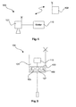
- Fig. 1 shows a meter assembly 100 according to an exemplary embodiment of the invention.
- the meter assembly 100 includes a TDR meter 101 for measuring a distance 103 to the surface 102 of a standing or flowing body 108.
- the measuring device 101 is connected to a communication unit 120, which can communicate with a corresponding communication unit 121 wirelessly (or by wire) to transmit data between the measuring device 101 and a control center 109 (see FIG Fig. 2 ).
- the measuring device 101 may alternatively be designed as a pressure gauge, or as a flowmeter for measuring the flow through a pipe.
- the measuring device 101 has a control unit 105 (see also Fig. 2 ), which is used to calculate a time for the next "distance measurement", in which case in the case of Fig. 1 is a level measurement. This time is calculated taking into account weather information at the location of the meter.
- weather information may also be considered concerning the weather at a remote location, for example upstream of the meter, or on a hill that is standing or flowing Water supplied with water.
- the level rises rapidly as a result of a change in the weather, it is desirable to measure at very short intervals and, if the rate of change of the level requires it, to report it to the control center.
- This level change can be predicted by taking into account the weather information, so that the measurement times can be calculated accordingly.
- the measurement intervals are adjusted to the current or expected future weather.
- the frequency of the distance measurement can be influenced by the weather forecasts to save energy while ensuring that level changes are detected early.
- the measured data are sent to the control center at the necessary times. If the connection has been established to the control center, after transmission the measured data the weather data or the time points for future measurements are transmitted to the meter. Thus, energy can be saved again.
- the measuring rate can be increased to the expected occurrence of the heavy rainfall (or possibly also a little later, if a corresponding level change is to be expected). Also in case of expected hailstorm or heavy snowfall. It is also possible to increase the measuring rate if a strong increase in temperature is expected, which leads to snowmelt, or if the departure of an avalanche is to be expected.
- the measuring rate may be reduced again after a specified delay time or after falling below a certain level. The same applies to the message to the control center.
- the energy thus saved in the meter can be used for additional measurements.
- the inclusion of the weather information at the location of the measuring device or upstream / upstream thereof is advantageous in order to be able to set the measuring rate as optimally as possible.
- measuring devices which are adapted to the conditions of use or environmental conditions and which perform different measuring methods. Examples include TDR devices, radar devices, ultrasound devices, hydrostatic devices, and radiometry devices.
- These meters can be used in locations where no power supply is available in the immediate vicinity. So come on These remote measuring devices battery or battery systems or solar powered supply systems are used as an energy source. To avoid a total failure of the battery or battery systems, they should be replaced or recharged in a timely manner. Since an exchange is often time-consuming and recharging of the batteries can not always be carried out automatically, the energy consumption of the sensors should be kept as low as possible. Energy consumption can be reduced by reducing the measuring rate and the amount of data exchanged between the sensor and the control center.
- measuring devices with a radio module 120 are also used, which are coupled to the control center via a radio network, such as GSM. Internet-based transmission protocols can also be used. These wireless modules also require energy. The energy requirement of the radio modules 120 can be significantly greater than the energy requirement for the actual measurement of the measuring device. Therefore, it is envisaged that, if possible, less often will be sent and received than measured.
- the level of the water body 108 is measured four times a day (or once a day), the measured values but only once a day (or every two days) transmitted to the control center.
- current weather data and the corresponding weather forecasts are queried by the sensor.
- the sensor can interrogate future measurement times (the evaluation of the weather data in this case does not take place in the sensor, but, for example, in the control center). It is also possible to obtain this data directly from an external service, which provides the weather data and possibly also takes over their evaluation. For example, this data is provided as an XML file from the external service to the control center or sensor.
- control center Based on these weather forecasts or weather reports, the control center adjusts the times for the measurements of the sensor (ie the measuring intervals) and the
- the level in the weather warning "heavy rain” is measured every 30 minutes, and every 80 minutes the measured data are transmitted to the control center, at least if the water level has changed sufficiently.
- the weather warning or weather forecast triggers an increased measurement rate in advance and the sensor itself takes into account the relative level change in a certain time range in order to control the messages to the control center in time.
- This method can be used to ensure that the sensor starts measuring in time, but does not consume unnecessary energy, as it automatically adapts the time points for future measurements as well as for the transmission of measured values to the level change rate.
- Fig. 2 shows a meter assembly 100 according to another exemplary embodiment of the invention.
- the measuring device 101 has a control unit 105 and a radio interface 120.
- the control station 109 remote from the measuring device also has a control unit 106 and a radio interface 121.
- a weather station 110 or an external weather service is provided, which also has a control unit 107 and a radio interface 122.
- the communication between the measuring device 101, the control center 109 and the weather service or the weather station 110 can take place via a cellular radio network or, for example, the Internet.
- Fig. 2 For the measuring device of Fig. 2
- it is a non-contact level radar device.
- Fig. 3 shows a flowchart of a method according to an exemplary embodiment of the invention.
- step 301 the acquisition of weather data takes place at the location and in the surroundings of the measuring device. From this weather data, weather information relating to the current or future expected weather at the location of the meter can be calculated (step 302).
- step 303 the time for a future measurement is then calculated from this weather information, possibly taking into account further information (time for the opening of a barrage, current rate of change of the water level).
- step 304 This point in time is then transmitted to the measuring device in step 304, and the measuring device determines the actual point in time for the next measurement in step 305, taking into account the history of previous measurements / water levels.
- step 306 the acquired measurement data is transmitted to the control center, since the field device has determined that the level has changed significantly compared to the previous measurement.
- Fig. 4 shows a measuring arrangement 100 according to another exemplary embodiment of the invention.
- the measuring device 101 is connected directly to a weather station 110, so that it thus receives the weather information directly from the weather station 110 and evaluates it itself.
- Fig. 5 shows another exemplary embodiment of the meter assembly 100, which in this case consists only of the meter 101.
- a central control unit 130 is provided, which contains the control units 105, 106, 107, so that the measuring device 101 can carry out all data collections and calculations independently.
- the field device 101 has a weather station 110 integrated therein. This may, for example, be a barometer.
Landscapes
- Engineering & Computer Science (AREA)
- Physics & Mathematics (AREA)
- Signal Processing (AREA)
- General Physics & Mathematics (AREA)
- Fluid Mechanics (AREA)
- Electromagnetism (AREA)
- Environmental & Geological Engineering (AREA)
- Life Sciences & Earth Sciences (AREA)
- Remote Sensing (AREA)
- Atmospheric Sciences (AREA)
- Biodiversity & Conservation Biology (AREA)
- Ecology (AREA)
- Environmental Sciences (AREA)
- Thermal Sciences (AREA)
- Radar, Positioning & Navigation (AREA)
- Hydrology & Water Resources (AREA)
- Arrangements For Transmission Of Measured Signals (AREA)
Abstract
Description
- Die Erfindung betrifft die Distanz- und Füllstandmessung. Insbesondere betrifft die Erfindung eine Messgeräteanordnung mit einem Messgerät zum Messen eines Abstands zu einem Objekt, ein Verfahren zum Messen eines Abstands eines Messgeräts zu einem Objekt, ein Programmelement und ein computerlesbares Medium.
- Bei Pegelstandmessungen fließender oder stehender Gewässer oder sonstigen Füllstand- oder Abstandmessungen, wie der Schneehöhenmessung im Gebirge, werden oft Messgeräte (Sensoren) mit Batterie- oder Akkuversorgung verwendet, da die Energieversorgung über ein Kabel meist nicht möglich oder zumindest nicht vorgesehen ist.
- Um die begrenzt vorhandene Energie über einen möglichst langen Zeitraum nutzen zu können, können die Zeiten zwischen zwei aufeinanderfolgenden Messungen verlängert werden. So genügt es üblicherweise, den Pegelstand eines Flusses einmal täglich zu messen. Rasche Änderungen des Pegelstands werden in diesem Falle jedoch unter Umständen erst mit mehrstündiger Verzögerung gemessen und der Leitstelle gemeldet.
- Es ist eine Aufgabe der Erfindung, den Energieverbrauch von Füllstand- oder Pegelstandmessgeräten gering zu halten und gleichzeitig den aktuellen Füll- bzw. Pegelstand mit möglichst geringer zeitlicher Verzögerung zu messen.
- Diese Aufgabe wird durch die Gegenstände der unabhängigen und nebengeordneten Patentansprüche gelöst. Weiterbildungen der Erfindung ergeben sich aus den Unteransprüchen sowie der folgenden Beschreibung von Aspekten in Ausführungsformen.
- Ein erster Aspekt der Erfindung betrifft eine Messgeräteanordnung mit einem Messgerät zum Messen eines Abstands zu einem Objekt, zum Messen eines Durchflusses oder eines Drucks. Bei der Messgeräteanordnung kann es sich beispielsweise um ein umfassendes Messsystem handeln, welches neben dem eigentlichen Messgerät noch weitere Einrichtungen aufweist, wie eine Leitstelle oder Zentrale und einen Wetterdienst.
- Bei dem Messgerät handelt es sich beispielsweise um ein Füllstandmessgerät, ein Durchflussmessgerät, ein Druckmessgerät oder ein Pegelmessgerät zum Bestimmen des Füllstands oder des Pegels eines Mediums, also insbesondere eines stehenden Gewässers, eines fließenden Gewässers oder von Schnee. Bei dem Messgerät kann es sich um ein berührungsfrei messendes Messgerät, beispielsweise ein Füllstandradar, handeln oder aber auch um ein nicht-berührungsfrei messendes Messgerät, welches beispielsweise einen Wellenleiter oder einen Resonator verwendet, der in das Medium hineinragt.
- Die Messgeräteanordnung weist eine oder mehrere Steuereinheiten auf. Zumindest eine dieser Steuereinheiten ist zum Berechnen eines Zeitpunkts für eine nächste Messung des Abstands ausgeführt, wobei die Berechnung des Zeitpunkts unter Berücksichtigung einer aktuellen und/oder einer prognostizierten Wetterinformation, die das Wetter am Ort des Messgeräts betrifft, erfolgt.
- Auch können bei der Berechnung des Zeitpunkts für die nächste Messung/die Berechnung der Zeitpunkte für die nächsten Messungen auch weitere Informationen Berücksichtigung finden, wie beispielsweise der Zeitpunkt, an dem eine Staustufe geöffnet wird (also Wasser abgelassen wird) oder eine Lawinensprengung vorgenommen werden soll.
- Die Steuereinheit, welche den Zeitpunkt für die nächste Messung des Abstands berechnet, kann beispielsweise in dem Messgerät selber integriert sein. Es kann aber auch vorgesehen sein, dass diese Steuereinheit in einem anderen Gerät integriert ist, beispielsweise in einer entfernt vom Messgerät angeordneten Leitstelle, die mit dem Messgerät kommunikativ verbindbar ist (beispielsweise über eine Funkschnittstelle).
- Die Steuereinheit kann auch in einer Wetterstation oder in einem System an Wetterstationen integriert sein, wobei in diesem Fall die Wetterstation bzw. das System an Wetterstationen zur Kommunikation mit dem Messgerät und/oder der Leitstelle ausgeführt ist, um die aktuelle und/oder prognostizierte Wetterinformation an das Messgerät oder die Leitstelle bereitzustellen.
- Somit ist es beispielsweise möglich, dass die Wetterstation die Wetterprognose an die Leitstelle übermittelt und diese daraufhin den passenden Zeitpunkt für eine zukünftige Abstandsmessung oder sogar mehrere passende Zeitpunkte für zukünftige Abstandsmessungen berechnet und an das Messgerät übermittelt. Somit kann die erforderliche Rechenleistung im Messgerät reduziert und gleichzeitig der Datentransfer zwischen dem Messgerät und der Leitstelle verringert werden. Insbesondere ist es auf diese Weise möglich, dass die Leitstelle dem Messgerät einen kompletten Messzyklus vorgibt, der die nächsten Tage zu befolgen ist. Es kann vorgesehen sein, dass das Messgerät diesen Messzyklus modifiziert, wenn sie beispielsweise die äußeren Umstände ändern, bzw. nicht so eintreten, wie dies von der Wettervorhersage prognostiziert wurde.
- Gemäß einer weiteren Ausführungsform der Erfindung berücksichtigt die Steuereinheit für das Berechnen des Zeitpunkts für die nächste Messung des Abstands neben der aktuellen und/oder prognostizierten Wetterinformation auch eine Historie vergangener, vom Messgerät durchgeführter Abstandsmessungen.
- So kann sich allein aus der Historie vergangener Abstandsmessungen ergeben, dass die Messfrequenz erhöht oder verringert werden muss, dass also der zeitliche Abstand zwischen zukünftigen Messungen verringert bzw. vergrößert werden muss, um Abstandsänderungen (wie Pegelstandänderungen, etc.) ausreichend frühzeitig erfassen zu können.
- Gemäß einer weiteren Ausführungsform der Erfindung ist die Steuereinheit des Messgeräts zum Bestimmen eines Zeitpunkts für die Übertragung von Messdaten an die Leitstelle unter Berücksichtigung der aktuellen oder prognostizierten Wetterinformation ausgeführt. Hierbei kann auch die zeitliche Änderung des Abstands des Objekts zum Messgerät berücksichtigt werden. Der Zeitpunkt für die Übertragung der Messdaten korreliert hierbei nicht zwingend mit dem Zeitpunkt der letzten Messung. Vielmehr kann die Berücksichtigung der Wetterinformationen und ggf. der Historie vergangener, vom Messgerät durchgeführter Abstandsmessungen sowie der Änderungsrate des Abstands ergeben, dass zum jetzigen Zeitpunkt keine Messwertübertragung an die Leitstelle notwendig ist, da sich der Pegel nicht oder nur geringfügig geändert hat. Auf diese Weise kann der Datentransfer zwischen Messgerät und Leitstelle weiter reduziert werden.
- Ein weiterer Aspekt der Erfindung betrifft ein Verfahren zum Messen eines Abstands eines Messgeräts zu einem Objekt, bei dem ein Zeitpunkt für die nächste Messung des Abstands unter Berücksichtigung einer aktuellen oder prognostizierten Wetterinformation, die das Wetter am Ort des Messgeräts betrifft, berücksichtigt wird.
- Ein weiterer Aspekt der Erfindung betrifft ein Programmelement, das, wenn es auf einer Steuereinheit einer Messgeräteanordnung, wie sie oben beschrieben wurde, ausgeführt wird, die Steuereinheit anleitet, das oben und im Folgenden beschriebene Verfahren durchzuführen.
- Ein weiterer Aspekt der Erfindung betrifft ein computerlesbares Medium, auf das das oben beschriebene Programmelement gespeichert ist.
- An dieser Stelle sei daraufhingewiesen, dass die oben und im Folgenden im Hinblick auf die Messgeräteanordnung beschriebenen Merkmale auch als Verfahrensschritte implementiert werden können und dass die Messgeräteanordnung ausgeführt sein kann, sämtliche oben und im Folgenden beschriebenen Verfahrensschritte durchzuführen.
- Im Folgenden werden mit Verweis auf die Figuren beispielhafte Ausführungsformen der Erfindung beschrieben.
-
-
Fig. 1 zeigt einen Teil einer Messgeräteanordnung gemäß einer beispielhaften Ausführungsform der Erfindung. -
Fig. 2 zeigt eine Messgeräteanordnung gemäß einer weiteren beispielhaften Ausführungsform der Erfindung. -
Fig. 3 zeigt ein Flussdiagramm eines Verfahrens gemäß einer beispielhaften Ausführungsform der Erfindung. -
Fig. 4 zeigt eine Messgeräteanordnung gemäß einer weiteren beispielhaften Ausführungsform der Erfindung. -
Fig. 5 zeigt eine Messgeräteanordnung gemäß einer weiteren beispielhaften Ausführungsform der Erfindung. - Die Darstellungen in den Figuren sind schematisch und nicht maßstäblich.
- Werden in der folgenden Figurenbeschreibung in verschiedenen Figuren die gleichen Bezugszeichen verwendet, so bezeichnen diese gleiche oder ähnliche Elemente. Gleiche oder ähnliche Elemente können aber auch durch unterschiedliche Bezugszeichen bezeichnet sein.
-
Fig. 1 zeigt eine Messgeräteanordnung 100 gemäß einer beispielhaften Ausführungsform der Erfindung. Die Messgeräteanordnung 100 weist ein TDR-Messgerät 101 zum Messen eines Abstands 103 zur Oberfläche 102 eines stehenden oder fließenden Gewässers 108 auf. Das Messgerät 101 ist an eine Kommunikationseinheit 120 angeschlossen, welche mit einer entsprechenden Kommunikationseinheit 121 drahtlos (oder drahtgebunden) kommunizieren kann, um Daten zwischen dem Messgerät 101 und einer Leitstelle 109 (sieheFig. 2 ) auszutauschen. - Das Messgerät 101 kann alternativ auch als Druckmessgerät ausgebildet sein, oder als Durchflussmessgerät zur Messung des Durchflusses durch eine Rohrleitung. Das Messgerät 101 weist eine Steuereinheit 105 (siehe ebenfalls
Fig. 2 ) auf, welche zum Berechnen eines Zeitpunkts für die nächste "Abstandsmessung", bei der es sich im Falle derFig. 1 um eine Pegelstandmessung handelt. Dieser Zeitpunkt wird unter Berücksichtigung von Wetterinformationen am Ort des Messgeräts berechnet. - Zusätzlich oder alternativ zur Wetterinformation, die den Ort, an dem das Messgerät installiert ist, betrifft, kann auch eine Wetterinformation Berücksichtigung finden, die das Wetter an einem entfernten Ort betrifft, beispielsweise stromaufwärts des Messgeräts, oder auf einem Berg, der das stehende oder fließende Gewässer mit Wasser versorgt.
- Steigt nun der Pegelstand infolge eines Wetterumschwungs rasch an, sind Messungen in sehr kurzen Zeitabständen wünschenswert und, falls die Änderungsrate des Pegels dies erforderlich macht, auch an die Leitstelle zu melden.
- Diese Pegelstandänderung kann durch die Berücksichtigung der Wetterinformationen vorhergesagt werden, so dass die Messzeitpunkte entsprechend berechnet werden können.
- In anderen Worten werden die Messintervalle an das aktuelle oder voraussichtlich zukünftige Wetter angepasst.
- Somit kann die Häufigkeit der Abstandsmessung durch die Wetterprognosen beeinflusst werden, um Energie zu sparen und gleichzeitig zu gewährleisten, dass Pegelstandänderungen frühzeitig erkannt werden.
- Die gemessenen Daten werden zu den notwendigen Zeitpunkten an die Leitstelle gesendet. Ist der Verbindungsaufbau zur Leitstelle erfolgt, können nach Übertragung der Messdaten die Wetterdaten oder die Zeitpunkte für zukünftige Messungen an das Messgerät übertragen werden. Somit kann nochmals Energie eingespart werden.
- Bei einer Wettermeldung "Starkregen" kann dementsprechend die Messrate zum erwarteten Eintritt des Starkregens (oder ggf. auch etwas später, wenn nämlich mit einer entsprechenden Pegeländerung zu rechnen ist) erhöht werden. Ebenso bei zu erwartendem Hagelschlag oder starkem Schneefall. Auch ist es möglich, die Messrate zu erhöhen, wenn ein starker Temperaturanstieg zu erwarten ist, der zur Schneeschmelze führt, oder wenn der Abgang einer Lawine zu erwarten ist.
- Ist das prognostizierte Ereignis (Starkregen, Hagelschlag, starker Schneefall, Lawinenabrutsch, Schneeschmelze) nicht eingetreten oder bereits erfolgt, kann die Messrate ggf. nach einer vorgegebenen Verzögerungszeit oder nach Unterschreitung eines bestimmten Pegels wieder verringert werden. Entsprechendes gilt auch für die Meldung an die Leitstelle.
- Die auf diese Weise im Messgerät gesparte Energie kann für zusätzliche Messungen verwendet werden.
- Da sich der Pegel eines Gewässers, beispielsweise eines Flusses oder eines Abwasserkanals, witterungsabhängig verändern kann, ist die Miteinbeziehung der Wetterinformation am Ort des Messgeräts bzw. strom-/bergaufwärts davon vorteilhaft, um die Messrate möglichst optimal einstellen zu können. Für derartige Pegel- bzw. Abstandsmessungen können auf die Einsatz- bzw. Umgebungsbedingungen angepasste Messgeräte verwendet werden, die unterschiedliche Messverfahren durchführen. Beispiele hierfür sind TDR-Geräte, Radar-Geräte, Ultraschall-Geräte, Hydrostatik-Geräte und Radiometrie-Geräte.
- Diese Messgeräte können an Orten eingesetzt werden, bei denen keine Energieversorgung in unmittelbarer Nähe zur Verfügung steht. So kommen bei diesen entfernt gelegenen Messgeräten Batterie- oder Akkusysteme oder auch solarbetriebene Versorgungssysteme als Energiequelle zum Einsatz. Um einen Totalausfall der Batterie- oder Akkusysteme zu vermeiden, sollten diese rechtzeitig ausgetauscht oder nachgeladen werden. Da ein Austausch oft aufwändig ist und ein Nachladen der Akkus sich nicht immer automatisch ausführen lässt, ist der Energieverbrauch der Sensoren möglichst gering zu halten. Der Energieverbrauch kann durch eine Reduzierung der Messrate und der zwischen Sensor und Leitstelle ausgetauschten Datenmenge verringert werden.
- Aufgrund der großen Entfernung zwischen Messgerät und Leitstelle kommen auch Messgeräte mit einem Funkmodul 120 zum Einsatz, welche über ein Funknetz, wie beispielsweise GSM, an die Leitstelle gekoppelt sind. Auch können internetbasierte Übertragungsprotokolle verwendet werden. Diese Funkmodule benötigen ebenfalls Energie. Der Energiebedarf der Funkmodule 120 kann deutlich größer sein als der Energiebedarf für die eigentliche Messung des Messgeräts. Deshalb ist vorgesehen, dass, falls möglich, weniger oft gesendet und empfangen wird als gemessen.
- Beispielsweise wird der Pegelstand des Gewässers 108 viermal täglich (oder einmal täglich) gemessen, die Messwerte jedoch nur einmal täglich (oder alle zwei Tage) an die Leitstelle übermittelt. Bei der Übermittlung der Messwerte an die Leitstelle werden aktuelle Wetterdaten und die entsprechenden Wetterprognosen vom Sensor abgefragt. Alternativ kann der Sensor zukünftige Messzeitpunkte abfragen (die Auswertung der Wetterdaten erfolgt in diesem Falle also nicht im Sensor, sondern beispielsweise in der Leitstelle). Es ist auch möglich, diese Daten direkt von einem externen Dienst zu beziehen, der die Wetterdaten bereitstellt und ggf. auch deren Auswertung übernimmt. Diese Daten werden beispielsweise als XML-Datei von dem externen Dienst an die Leitstelle oder den Sensor bereitgestellt.
- Aufgrund dieser Wetterprognosen oder Wettermeldungen passt die Leitstelle die Zeitpunkte für die Messungen des Sensors (also die Messintervalle) und die
- Sendeintervalle für den Datentransfer vom Sensor an die Leitstelle an. So wird beispielsweise der Pegel bei der Wetterwarnung "Starkregen" alle 30 Minuten gemessen und alle 80 Minuten werden die Messdaten an die Leitstelle übermittelt, zumindest falls sich der Pegelstand hinreichend geändert hat.
- Für einige Anwendungen ist vorgesehen, dass die Wetterwarnung oder Wetterprognose im Vorfeld eine erhöhte Messrate auslöst und der Sensor selbst die relative Pegeländerung in einem bestimmten Zeitbereich berücksichtigt, um die Meldungen an die Leitstelle zeitlich zu steuern. Mit dieser Methode kann sichergestellt werden, dass der Sensor noch rechtzeitig mit der Messung beginnt, aber nicht unnötig viel Energie verbraucht, da er die Zeitpunkte für zukünftige Messungen sowie für die Übertragung der Messwerte selbständig an die Pegeländerungsrate anpasst.
-
Fig. 2 zeigt eine Messgeräteanordnung 100 gemäß einer weiteren beispielhaften Ausführungsform der Erfindung. Das Messgerät 101 weist eine Steuereinheit 105 sowie eine Funkschnittstelle 120 auf. Die entfernt zum Messgerät angeordnete Leitstelle 109 weist ebenfalls eine Steuereinheit 106 und eine Funkschnittstelle 121 auf. Darüber hinaus ist eine Wetterstation 110 bzw. ein externer Wetterdienst vorgesehen, die/der ebenfalls eine Steuereinheit 107 sowie eine Funkschnittstelle 122 aufweist. - Die Kommunikation zwischen dem Messgerät 101, der Leitstelle 109 und dem Wetterdienst bzw. der Wetterstation 110 kann über ein zelluläres Funknetzwerk oder beispielsweise das Internet erfolgen.
- Bei dem Messgerät der
Fig. 2 handelt es sich beispielsweise um ein berührungslos arbeitendes Füllstandradargerät. -
Fig. 3 zeigt ein Flussdiagramm eines Verfahrens gemäß einer beispielhaften Ausführungsform der Erfindung. In Schritt 301 erfolgt die Erfassung von Wetterdaten am Ort und in der Umgebung des Messgeräts. Aus diesen Wetterdaten kann eine Wetterinformation, die das aktuelle oder das zukünftig zu erwartende Wetter am Ort des Messgeräts betrifft, berechnet werden (Schritt 302). In Schritt 303 wird dann aus dieser Wetterinformation, ggf. unter Berücksichtigung weiterer Informationen (Zeitpunkt für das Öffnen einer Staustufe, aktuelle Änderungsrate des Pegelstandes), der Zeitpunkt für eine zukünftige Messung berechnet. - Dieser Zeitpunkt wird dann in Schritt 304 an das Messgerät übermittelt und das Messgerät bestimmt in Schritt 305 unter Berücksichtigung der Historie bisheriger Messungen/Pegelstände den tatsächlichen Zeitpunkt für die nächste Messung. In Schritt 306 werden die erfassten Messdaten an die Leitstelle übermittelt, da das Feldgerät festgestellt hat, dass sich der Pegel im Vergleich zur vorherigen Messung doch deutlich geändert hat.
-
Fig. 4 zeigt eine Messanordnung 100 gemäß einer weiteren beispielhaften Ausführungsform der Erfindung. Das Messgerät 101 ist direkt an eine Wetterstation 110 angeschlossen, so dass es die Wetterinformation somit direkt von der Wetterstation 110 erhält und selber auswertet. -
Fig. 5 zeigt eine weitere beispielhafte Ausführungsform der Messgeräteanordnung 100, die in diesem Fall lediglich aus dem Messgerät 101 besteht. Es ist eine zentrale Steuereinheit 130 vorgesehen, welche die Steuereinheiten 105, 106, 107 beinhaltet, so dass das Messgerät 101 sämtliche Datenerhebungen und Berechnungen selbstständig durchführen kann. Insbesondere weist das Feldgerät 101 eine darin integrierte Wetterstation 110 auf. Hierbei kann es sich beispielsweise um ein Barometer handeln. - Ergänzend sei daraufhingewiesen, dass "umfassend" und "aufweisend" keine anderen Elemente oder Schritte ausschließt und "eine" oder "ein" keine Vielzahl ausschließt. Ferner sei darauf hingewiesen, dass Merkmale oder Schritte, die mit Verweis auf eine der obigen Ausführungsformen beschrieben worden sind, auch in Kombination mit anderen Merkmalen oder Schritten anderer oben beschriebener Ausführungsformen verwendet werden können. Bezugszeichen in den Ansprüchen sind nicht als Einschränkungen anzusehen.
Claims (11)
- Messgeräteanordnung (100) mit einem Messgerät (101) zum Messen eines Abstands , eines Druckes oder eines Durchflusses (103) zu einem Objekt (104), aufweisend:eine Steuereinheit (105, 106, 107) zum Berechnen eines Zeitpunkts für eine nächste Messung des Abstands, des Drucks oder des Durchflusses, unter Berücksichtigung einer aktuellen oder prognostizierten Wetterinformation, die das Wetter am Ort des Messgeräts betrifft.
- Messgeräteanordnung (100) nach Anspruch 1,
wobei es sich bei dem Messgerät (101) um ein Messgerät zum Messen eines Füllstands oder eines Pegels eines Mediums (108) handelt. - Messgeräteanordnung (100) nach einem der vorhergehenden Ansprüche,
wobei die Steuereinheit (105) in dem Messgerät (101) integriert ist. - Messgeräteanordnung (100) nach einem der vorhergehenden Ansprüche, weiter aufweisend:eine Leitstelle (109), die entfernt zum Messgerät (101) angeordnet ist und zur Kommunikation mit dem Messgerät (101) ausgeführt ist;wobei die Steuereinheit (106) in der Leitstelle (109) integriert ist.
- Messgeräteanordnung (100) nach einem der vorhergehenden Ansprüche, weiter aufweisend:eine Wetterstation (110), die zur Kommunikation mit dem Messgerät oder der Leitstelle (109) ausgeführt ist, zum Bereitstellen der aktuellen oder prognostizierten Wetterinformation an das Messgerät oder die Leitstelle.
- Messgeräteanordnung (100) nach einem der vorhergehenden Ansprüche,
wobei die Steuereinheit (105, 106, 107) für das Berechnen des Zeitpunkts für die nächste Messung des Abstands auch eine Historie vergangener, vom Messgerät durchgeführter Abstandmessungen berücksichtigt. - Messgeräteanordnung (100) nach einem der vorhergehenden Ansprüche, aufweisend:eine Leitstelle (109), die entfernt zum Messgerät (101) angeordnet ist und zur Kommunikation mit dem Messgerät (101) ausgeführt ist;wobei die Steuereinheit (105) des Messgeräts (101) zum Bestimmen eines Zeitpunkts für die Übertragung von Messdaten an die Leitstelle unter Berücksichtigung der aktuellen oder prognostizierten Wetterinformation und einer Änderungsrate des Abstands ausgeführt ist;wobei der Zeitpunkt für die Übertragung der Messdaten an die Leitstelle nicht zwingend mit dem Zeitpunkt der letzten Messung korreliert.
- Messgeräteanordnung (100) nach Anspruch 7,
wobei der Zeitpunkt für die Übertragung von Messdaten an die Leitstelle (109) von einer Änderungsrate des gemessenen Abstands (103) abhängig ist. - Verfahren zum Messen eines Abstands (103) eines Messgeräts (101) zu einem Objekt (104), zum Messen eines Drucks oder zum Messen eines Durchflusses, aufweisend den Schritt:Berechnen eines Zeitpunkts für eine nächste Messung des Abstands, des Drucks oder des Durchflusses, unter Berücksichtigung einer aktuellen oder prognostizierten Wetterinformation, die das Wetter am Ort des Messgeräts betrifft.
- Programmelement, das, wenn es auf einer Steuereinheit (105, 106, 107) einer Messgeräteanordnung (100) ausgeführt wird, die Steuereinheit anleitet, den folgenden Schritt durchzuführen:Berechnen eines Zeitpunkts für eine nächste Messung des Abstands, des Drucks oder des Durchflusses, unter Berücksichtigung einer aktuellen oder prognostizierten Wetterinformation, die das Wetter am Ort des Messgeräts betrifft.
- Computerlesbares Medium, auf dem ein Programmelement nach Anspruch 10 gespeichert ist.
Priority Applications (3)
| Application Number | Priority Date | Filing Date | Title |
|---|---|---|---|
| EP14198153.0A EP3035010B1 (de) | 2014-12-16 | 2014-12-16 | Wetterdatenabhängige Füllstandsensorabfrage |
| US14/937,275 US10024705B2 (en) | 2014-12-16 | 2015-11-10 | Weather data-dependent level sensor retrieval |
| CN201510888091.1A CN105698771B (zh) | 2014-12-16 | 2015-12-07 | 取决于气象数据的物位传感器提取 |
Applications Claiming Priority (1)
| Application Number | Priority Date | Filing Date | Title |
|---|---|---|---|
| EP14198153.0A EP3035010B1 (de) | 2014-12-16 | 2014-12-16 | Wetterdatenabhängige Füllstandsensorabfrage |
Publications (2)
| Publication Number | Publication Date |
|---|---|
| EP3035010A1 true EP3035010A1 (de) | 2016-06-22 |
| EP3035010B1 EP3035010B1 (de) | 2018-04-11 |
Family
ID=52231844
Family Applications (1)
| Application Number | Title | Priority Date | Filing Date |
|---|---|---|---|
| EP14198153.0A Active EP3035010B1 (de) | 2014-12-16 | 2014-12-16 | Wetterdatenabhängige Füllstandsensorabfrage |
Country Status (3)
| Country | Link |
|---|---|
| US (1) | US10024705B2 (de) |
| EP (1) | EP3035010B1 (de) |
| CN (1) | CN105698771B (de) |
Cited By (4)
| Publication number | Priority date | Publication date | Assignee | Title |
|---|---|---|---|---|
| EP3598078B1 (de) * | 2018-07-20 | 2021-05-12 | VEGA Grieshaber KG | Batteriebetriebenes feldgerät mit zeitinformationsübermittlung |
| DE102020006021A1 (de) | 2020-09-30 | 2022-03-31 | Karlsruher Institut für Technologie | Grundwassersonde; Grundwassersondensystem und Verfahren |
| US12061943B2 (en) | 2018-07-20 | 2024-08-13 | Vega Grieshaber Kg | Measuring device with near field interaction device |
| US12452785B2 (en) | 2019-12-17 | 2025-10-21 | Vega Grieshaber Kg | Sensor for generating power management data |
Families Citing this family (7)
| Publication number | Priority date | Publication date | Assignee | Title |
|---|---|---|---|---|
| EP3719456A4 (de) * | 2017-11-28 | 2020-11-25 | Fujitsu Limited | Messsteuerungsprogramm, messsteuerungsverfahren, messsteuerungsvorrichtung und messsteuerungssystem |
| EP3754309B1 (de) * | 2019-06-19 | 2023-03-29 | Rosemount Tank Radar AB | Radarpegelmessung mit leistungsabhängiger anzahl von messvorgängen |
| GB202002441D0 (en) | 2020-02-21 | 2020-04-08 | Res & Innovation Uk | Measuring snowfall |
| DE102020118681A1 (de) | 2020-07-15 | 2022-01-20 | Krohne Messtechnik Gmbh | Verfahren zum Betreiben eines Schlammspiegelmessgeräts und ein entsprechendes Schlammspiegelmessgerät |
| CN115597614A (zh) * | 2021-07-08 | 2023-01-13 | 博泰车联网科技(上海)股份有限公司(Cn) | 路径规划方法、系统、电子设备、介质及车辆 |
| DE102023114705A1 (de) | 2023-06-05 | 2024-12-05 | Vega Grieshaber Kg | Messgerät zur Prozessautomatisierung im industriellen oder privaten Umfeld |
| EP4600617A1 (de) * | 2024-02-08 | 2025-08-13 | VEGA Grieshaber KG | Verfahren zum steuern einer messdauer und/oder eines messabstands |
Citations (4)
| Publication number | Priority date | Publication date | Assignee | Title |
|---|---|---|---|---|
| US2906026A (en) * | 1957-03-14 | 1959-09-29 | Francis P Hanes | Liquid level telemetering device |
| DE3239920A1 (de) * | 1982-10-28 | 1984-05-03 | Franz 7024 Filderstadt Eggs | Verfahren zum messen der menge von am boden von muelldeponien abfliessender verunreinigter fluessigkeit sowie einrichtung zu seiner durchfuehrung |
| US5239203A (en) * | 1990-03-30 | 1993-08-24 | Texand Corporation | Common ground control switch for an irrigation system |
| WO2009082473A1 (en) * | 2007-12-20 | 2009-07-02 | Kah Carl L C Jr | Wireless moisture probe, receiving controller and irrigation control system |
Family Cites Families (5)
| Publication number | Priority date | Publication date | Assignee | Title |
|---|---|---|---|---|
| DE19537850A1 (de) | 1995-10-11 | 1997-04-17 | Harald Reibnagel | Codierer und Decodierer von Wettervorhersagen |
| DE102005032621B4 (de) | 2004-07-19 | 2021-05-20 | Vaillant Gmbh | Verfahren zur Regelung eines Heiz-, Kühl- und/oder Klimatisierungsgerätes |
| US8591147B2 (en) * | 2009-11-20 | 2013-11-26 | Geosyntec Consultants, Inc. | Combined water storage and detention system and method of precipitation harvesting and management |
| WO2011159620A2 (en) * | 2010-06-14 | 2011-12-22 | Rainbank, Inc. | Methods and systems for monitoring, controlling, and recording performance of a storm water runoff network |
| FI20115526L (fi) * | 2011-05-27 | 2012-11-28 | Meritaito Oy | Menetelmä, systeemi ja laite navigoitavaa väylää koskevan informaation tuottamiseksi |
-
2014
- 2014-12-16 EP EP14198153.0A patent/EP3035010B1/de active Active
-
2015
- 2015-11-10 US US14/937,275 patent/US10024705B2/en active Active
- 2015-12-07 CN CN201510888091.1A patent/CN105698771B/zh active Active
Patent Citations (4)
| Publication number | Priority date | Publication date | Assignee | Title |
|---|---|---|---|---|
| US2906026A (en) * | 1957-03-14 | 1959-09-29 | Francis P Hanes | Liquid level telemetering device |
| DE3239920A1 (de) * | 1982-10-28 | 1984-05-03 | Franz 7024 Filderstadt Eggs | Verfahren zum messen der menge von am boden von muelldeponien abfliessender verunreinigter fluessigkeit sowie einrichtung zu seiner durchfuehrung |
| US5239203A (en) * | 1990-03-30 | 1993-08-24 | Texand Corporation | Common ground control switch for an irrigation system |
| WO2009082473A1 (en) * | 2007-12-20 | 2009-07-02 | Kah Carl L C Jr | Wireless moisture probe, receiving controller and irrigation control system |
Cited By (5)
| Publication number | Priority date | Publication date | Assignee | Title |
|---|---|---|---|---|
| EP3598078B1 (de) * | 2018-07-20 | 2021-05-12 | VEGA Grieshaber KG | Batteriebetriebenes feldgerät mit zeitinformationsübermittlung |
| US11385089B2 (en) | 2018-07-20 | 2022-07-12 | Vega Grieshaber Kg | Battery-operated field device with time transmission |
| US12061943B2 (en) | 2018-07-20 | 2024-08-13 | Vega Grieshaber Kg | Measuring device with near field interaction device |
| US12452785B2 (en) | 2019-12-17 | 2025-10-21 | Vega Grieshaber Kg | Sensor for generating power management data |
| DE102020006021A1 (de) | 2020-09-30 | 2022-03-31 | Karlsruher Institut für Technologie | Grundwassersonde; Grundwassersondensystem und Verfahren |
Also Published As
| Publication number | Publication date |
|---|---|
| US10024705B2 (en) | 2018-07-17 |
| CN105698771A (zh) | 2016-06-22 |
| EP3035010B1 (de) | 2018-04-11 |
| CN105698771B (zh) | 2020-03-13 |
| US20160169729A1 (en) | 2016-06-16 |
Similar Documents
| Publication | Publication Date | Title |
|---|---|---|
| EP3035010B1 (de) | Wetterdatenabhängige Füllstandsensorabfrage | |
| EP2239955B1 (de) | Energiegesteuerte Datenübermittlung eines Feldgeräts | |
| EP2591534B1 (de) | Verfahren zur steuerung von pv-anlagen in einem stromversorgungsnetz | |
| CN205121825U (zh) | 一种尾矿库安全监测系统 | |
| EP1828670A2 (de) | Leitungsnetzwerk zur versorgung mit wasser oder gas und/oder zum abtransport von brauchwasser mit einer hierarchischen struktur, verfahren zur detektion einer leckage in einem solchen leitungsnetz und verfahren zur rechnergestützten bestimmung einer theoretisch verbleibenden lebensdauer einer erneuer | |
| EP3072197A1 (de) | Verfahren und windenergieanlage zur blitzwarnung | |
| EP2650740A1 (de) | Verfahren zum Einrichten einer temporären Empfangsbereitschaft eines Feldgeräts und Messsystem | |
| DE102019108781A1 (de) | Computergestütztes Verfahren und Einrichtung zur optimierten Steuerung der Förderleistung einer Betonpumpe oder dergleichen | |
| EP3637064A1 (de) | Batteriebetriebenes füllstandmessgerät mit restlebensdauerbestimmungsvorrichtung | |
| CN205102881U (zh) | 一种分布式水位测量装置 | |
| CN105501884A (zh) | 一种矿山产能远程监测与服务系统 | |
| DE102015219282A1 (de) | Pegelstanddifferenzmessung mit Master-Slave-Konzept | |
| DE102017002297B4 (de) | Kreiselpumpenaggregat mit Volumenstromsensor | |
| DE102017113213A1 (de) | Anordnung zur Zusammenstellung und/oder Bestimmung der Wagenreihung und/oder Überprüfung der Vollständigkeit eines Schienenfahrzeugs, ein Verfahren und dessen Verwendung | |
| DE102012103108A1 (de) | System und Verfahren zur Messung und Speicherung meteorologischer Daten | |
| DE102018119409A1 (de) | System zur Füllstandsüberwachung eines Behälters | |
| EP3467454B1 (de) | Messsystem zum ermitteln und überwachen von messwerten für bestimmte physikalische grössen und verfahren zum betrieb eines solchen messsystems | |
| CN210893240U (zh) | 水力管道中应用的多功能水力传感装置 | |
| CN203489874U (zh) | 一种路基沉降自动监测系统 | |
| EP4212826B1 (de) | Schleppzeiger zum berechnen einer prozessmessgrösse | |
| DE102020108989A1 (de) | Wasserzähler und Verfahren zur Befestigung eines Wasserzählers an einer Wasserleitung | |
| DE102021203000B4 (de) | Verfahren zum Betrieb einer Heizkostenverteilervorrichtung und Heizkostenverteilervorrichtung | |
| CN205003301U (zh) | 一种联动式远程雨量监测设备 | |
| LU501376B1 (de) | Verfahren, Gerät, Meidum und Erosionsüberwachungssystem zur Echtzeit-Überwachung der Stranderosion durch Radar | |
| DE102022107252B3 (de) | Vorrichtung zum Übertragen von Sensordaten |
Legal Events
| Date | Code | Title | Description |
|---|---|---|---|
| PUAI | Public reference made under article 153(3) epc to a published international application that has entered the european phase |
Free format text: ORIGINAL CODE: 0009012 |
|
| 17P | Request for examination filed |
Effective date: 20151202 |
|
| AK | Designated contracting states |
Kind code of ref document: A1 Designated state(s): AL AT BE BG CH CY CZ DE DK EE ES FI FR GB GR HR HU IE IS IT LI LT LU LV MC MK MT NL NO PL PT RO RS SE SI SK SM TR |
|
| AX | Request for extension of the european patent |
Extension state: BA ME |
|
| STAA | Information on the status of an ep patent application or granted ep patent |
Free format text: STATUS: EXAMINATION IS IN PROGRESS |
|
| GRAP | Despatch of communication of intention to grant a patent |
Free format text: ORIGINAL CODE: EPIDOSNIGR1 |
|
| STAA | Information on the status of an ep patent application or granted ep patent |
Free format text: STATUS: GRANT OF PATENT IS INTENDED |
|
| INTG | Intention to grant announced |
Effective date: 20171114 |
|
| GRAS | Grant fee paid |
Free format text: ORIGINAL CODE: EPIDOSNIGR3 |
|
| GRAA | (expected) grant |
Free format text: ORIGINAL CODE: 0009210 |
|
| STAA | Information on the status of an ep patent application or granted ep patent |
Free format text: STATUS: THE PATENT HAS BEEN GRANTED |
|
| AK | Designated contracting states |
Kind code of ref document: B1 Designated state(s): AL AT BE BG CH CY CZ DE DK EE ES FI FR GB GR HR HU IE IS IT LI LT LU LV MC MK MT NL NO PL PT RO RS SE SI SK SM TR |
|
| REG | Reference to a national code |
Ref country code: GB Ref legal event code: FG4D Free format text: NOT ENGLISH |
|
| REG | Reference to a national code |
Ref country code: CH Ref legal event code: EP |
|
| REG | Reference to a national code |
Ref country code: AT Ref legal event code: REF Ref document number: 988537 Country of ref document: AT Kind code of ref document: T Effective date: 20180415 |
|
| REG | Reference to a national code |
Ref country code: IE Ref legal event code: FG4D Free format text: LANGUAGE OF EP DOCUMENT: GERMAN |
|
| REG | Reference to a national code |
Ref country code: DE Ref legal event code: R096 Ref document number: 502014007918 Country of ref document: DE |
|
| REG | Reference to a national code |
Ref country code: NL Ref legal event code: MP Effective date: 20180411 |
|
| REG | Reference to a national code |
Ref country code: LT Ref legal event code: MG4D |
|
| PG25 | Lapsed in a contracting state [announced via postgrant information from national office to epo] |
Ref country code: NL Free format text: LAPSE BECAUSE OF FAILURE TO SUBMIT A TRANSLATION OF THE DESCRIPTION OR TO PAY THE FEE WITHIN THE PRESCRIBED TIME-LIMIT Effective date: 20180411 |
|
| PG25 | Lapsed in a contracting state [announced via postgrant information from national office to epo] |
Ref country code: AL Free format text: LAPSE BECAUSE OF FAILURE TO SUBMIT A TRANSLATION OF THE DESCRIPTION OR TO PAY THE FEE WITHIN THE PRESCRIBED TIME-LIMIT Effective date: 20180411 Ref country code: BG Free format text: LAPSE BECAUSE OF FAILURE TO SUBMIT A TRANSLATION OF THE DESCRIPTION OR TO PAY THE FEE WITHIN THE PRESCRIBED TIME-LIMIT Effective date: 20180711 Ref country code: SE Free format text: LAPSE BECAUSE OF FAILURE TO SUBMIT A TRANSLATION OF THE DESCRIPTION OR TO PAY THE FEE WITHIN THE PRESCRIBED TIME-LIMIT Effective date: 20180411 Ref country code: FI Free format text: LAPSE BECAUSE OF FAILURE TO SUBMIT A TRANSLATION OF THE DESCRIPTION OR TO PAY THE FEE WITHIN THE PRESCRIBED TIME-LIMIT Effective date: 20180411 Ref country code: PL Free format text: LAPSE BECAUSE OF FAILURE TO SUBMIT A TRANSLATION OF THE DESCRIPTION OR TO PAY THE FEE WITHIN THE PRESCRIBED TIME-LIMIT Effective date: 20180411 Ref country code: NO Free format text: LAPSE BECAUSE OF FAILURE TO SUBMIT A TRANSLATION OF THE DESCRIPTION OR TO PAY THE FEE WITHIN THE PRESCRIBED TIME-LIMIT Effective date: 20180711 Ref country code: LT Free format text: LAPSE BECAUSE OF FAILURE TO SUBMIT A TRANSLATION OF THE DESCRIPTION OR TO PAY THE FEE WITHIN THE PRESCRIBED TIME-LIMIT Effective date: 20180411 Ref country code: ES Free format text: LAPSE BECAUSE OF FAILURE TO SUBMIT A TRANSLATION OF THE DESCRIPTION OR TO PAY THE FEE WITHIN THE PRESCRIBED TIME-LIMIT Effective date: 20180411 |
|
| PG25 | Lapsed in a contracting state [announced via postgrant information from national office to epo] |
Ref country code: HR Free format text: LAPSE BECAUSE OF FAILURE TO SUBMIT A TRANSLATION OF THE DESCRIPTION OR TO PAY THE FEE WITHIN THE PRESCRIBED TIME-LIMIT Effective date: 20180411 Ref country code: GR Free format text: LAPSE BECAUSE OF FAILURE TO SUBMIT A TRANSLATION OF THE DESCRIPTION OR TO PAY THE FEE WITHIN THE PRESCRIBED TIME-LIMIT Effective date: 20180712 Ref country code: LV Free format text: LAPSE BECAUSE OF FAILURE TO SUBMIT A TRANSLATION OF THE DESCRIPTION OR TO PAY THE FEE WITHIN THE PRESCRIBED TIME-LIMIT Effective date: 20180411 Ref country code: RS Free format text: LAPSE BECAUSE OF FAILURE TO SUBMIT A TRANSLATION OF THE DESCRIPTION OR TO PAY THE FEE WITHIN THE PRESCRIBED TIME-LIMIT Effective date: 20180411 |
|
| PG25 | Lapsed in a contracting state [announced via postgrant information from national office to epo] |
Ref country code: PT Free format text: LAPSE BECAUSE OF FAILURE TO SUBMIT A TRANSLATION OF THE DESCRIPTION OR TO PAY THE FEE WITHIN THE PRESCRIBED TIME-LIMIT Effective date: 20180813 |
|
| REG | Reference to a national code |
Ref country code: DE Ref legal event code: R097 Ref document number: 502014007918 Country of ref document: DE |
|
| PG25 | Lapsed in a contracting state [announced via postgrant information from national office to epo] |
Ref country code: RO Free format text: LAPSE BECAUSE OF FAILURE TO SUBMIT A TRANSLATION OF THE DESCRIPTION OR TO PAY THE FEE WITHIN THE PRESCRIBED TIME-LIMIT Effective date: 20180411 Ref country code: CZ Free format text: LAPSE BECAUSE OF FAILURE TO SUBMIT A TRANSLATION OF THE DESCRIPTION OR TO PAY THE FEE WITHIN THE PRESCRIBED TIME-LIMIT Effective date: 20180411 Ref country code: EE Free format text: LAPSE BECAUSE OF FAILURE TO SUBMIT A TRANSLATION OF THE DESCRIPTION OR TO PAY THE FEE WITHIN THE PRESCRIBED TIME-LIMIT Effective date: 20180411 Ref country code: DK Free format text: LAPSE BECAUSE OF FAILURE TO SUBMIT A TRANSLATION OF THE DESCRIPTION OR TO PAY THE FEE WITHIN THE PRESCRIBED TIME-LIMIT Effective date: 20180411 Ref country code: SK Free format text: LAPSE BECAUSE OF FAILURE TO SUBMIT A TRANSLATION OF THE DESCRIPTION OR TO PAY THE FEE WITHIN THE PRESCRIBED TIME-LIMIT Effective date: 20180411 |
|
| PLBE | No opposition filed within time limit |
Free format text: ORIGINAL CODE: 0009261 |
|
| STAA | Information on the status of an ep patent application or granted ep patent |
Free format text: STATUS: NO OPPOSITION FILED WITHIN TIME LIMIT |
|
| PG25 | Lapsed in a contracting state [announced via postgrant information from national office to epo] |
Ref country code: SM Free format text: LAPSE BECAUSE OF FAILURE TO SUBMIT A TRANSLATION OF THE DESCRIPTION OR TO PAY THE FEE WITHIN THE PRESCRIBED TIME-LIMIT Effective date: 20180411 Ref country code: IT Free format text: LAPSE BECAUSE OF FAILURE TO SUBMIT A TRANSLATION OF THE DESCRIPTION OR TO PAY THE FEE WITHIN THE PRESCRIBED TIME-LIMIT Effective date: 20180411 |
|
| 26N | No opposition filed |
Effective date: 20190114 |
|
| PG25 | Lapsed in a contracting state [announced via postgrant information from national office to epo] |
Ref country code: SI Free format text: LAPSE BECAUSE OF FAILURE TO SUBMIT A TRANSLATION OF THE DESCRIPTION OR TO PAY THE FEE WITHIN THE PRESCRIBED TIME-LIMIT Effective date: 20180411 |
|
| REG | Reference to a national code |
Ref country code: CH Ref legal event code: PL |
|
| GBPC | Gb: european patent ceased through non-payment of renewal fee |
Effective date: 20181216 |
|
| PG25 | Lapsed in a contracting state [announced via postgrant information from national office to epo] |
Ref country code: LU Free format text: LAPSE BECAUSE OF NON-PAYMENT OF DUE FEES Effective date: 20181216 Ref country code: MC Free format text: LAPSE BECAUSE OF FAILURE TO SUBMIT A TRANSLATION OF THE DESCRIPTION OR TO PAY THE FEE WITHIN THE PRESCRIBED TIME-LIMIT Effective date: 20180411 |
|
| REG | Reference to a national code |
Ref country code: IE Ref legal event code: MM4A |
|
| REG | Reference to a national code |
Ref country code: BE Ref legal event code: MM Effective date: 20181231 |
|
| PG25 | Lapsed in a contracting state [announced via postgrant information from national office to epo] |
Ref country code: IE Free format text: LAPSE BECAUSE OF NON-PAYMENT OF DUE FEES Effective date: 20181216 Ref country code: FR Free format text: LAPSE BECAUSE OF NON-PAYMENT OF DUE FEES Effective date: 20181231 |
|
| PG25 | Lapsed in a contracting state [announced via postgrant information from national office to epo] |
Ref country code: BE Free format text: LAPSE BECAUSE OF NON-PAYMENT OF DUE FEES Effective date: 20181231 |
|
| PG25 | Lapsed in a contracting state [announced via postgrant information from national office to epo] |
Ref country code: LI Free format text: LAPSE BECAUSE OF NON-PAYMENT OF DUE FEES Effective date: 20181231 Ref country code: CH Free format text: LAPSE BECAUSE OF NON-PAYMENT OF DUE FEES Effective date: 20181231 Ref country code: GB Free format text: LAPSE BECAUSE OF NON-PAYMENT OF DUE FEES Effective date: 20181216 |
|
| PG25 | Lapsed in a contracting state [announced via postgrant information from national office to epo] |
Ref country code: MT Free format text: LAPSE BECAUSE OF FAILURE TO SUBMIT A TRANSLATION OF THE DESCRIPTION OR TO PAY THE FEE WITHIN THE PRESCRIBED TIME-LIMIT Effective date: 20180411 |
|
| PG25 | Lapsed in a contracting state [announced via postgrant information from national office to epo] |
Ref country code: TR Free format text: LAPSE BECAUSE OF FAILURE TO SUBMIT A TRANSLATION OF THE DESCRIPTION OR TO PAY THE FEE WITHIN THE PRESCRIBED TIME-LIMIT Effective date: 20180411 |
|
| PG25 | Lapsed in a contracting state [announced via postgrant information from national office to epo] |
Ref country code: HU Free format text: LAPSE BECAUSE OF FAILURE TO SUBMIT A TRANSLATION OF THE DESCRIPTION OR TO PAY THE FEE WITHIN THE PRESCRIBED TIME-LIMIT; INVALID AB INITIO Effective date: 20141216 Ref country code: MK Free format text: LAPSE BECAUSE OF NON-PAYMENT OF DUE FEES Effective date: 20180411 Ref country code: CY Free format text: LAPSE BECAUSE OF FAILURE TO SUBMIT A TRANSLATION OF THE DESCRIPTION OR TO PAY THE FEE WITHIN THE PRESCRIBED TIME-LIMIT Effective date: 20180411 |
|
| PG25 | Lapsed in a contracting state [announced via postgrant information from national office to epo] |
Ref country code: IS Free format text: LAPSE BECAUSE OF FAILURE TO SUBMIT A TRANSLATION OF THE DESCRIPTION OR TO PAY THE FEE WITHIN THE PRESCRIBED TIME-LIMIT Effective date: 20180811 |
|
| P01 | Opt-out of the competence of the unified patent court (upc) registered |
Effective date: 20230508 |
|
| PGFP | Annual fee paid to national office [announced via postgrant information from national office to epo] |
Ref country code: AT Payment date: 20251215 Year of fee payment: 12 |
|
| PGFP | Annual fee paid to national office [announced via postgrant information from national office to epo] |
Ref country code: DE Payment date: 20251222 Year of fee payment: 12 |